JP5959264B2 - Image processing apparatus and method, and computer program - Google Patents
Image processing apparatus and method, and computer program Download PDFInfo
- Publication number
- JP5959264B2 JP5959264B2 JP2012075962A JP2012075962A JP5959264B2 JP 5959264 B2 JP5959264 B2 JP 5959264B2 JP 2012075962 A JP2012075962 A JP 2012075962A JP 2012075962 A JP2012075962 A JP 2012075962A JP 5959264 B2 JP5959264 B2 JP 5959264B2
- Authority
- JP
- Japan
- Prior art keywords
- image
- distance information
- unit
- shape
- model
- Prior art date
- Legal status (The legal status is an assumption and is not a legal conclusion. Google has not performed a legal analysis and makes no representation as to the accuracy of the status listed.)
- Active
Links
- 238000012545 processing Methods 0.000 title claims description 32
- 238000004590 computer program Methods 0.000 title claims description 4
- 238000000034 method Methods 0.000 title description 8
- 238000003384 imaging method Methods 0.000 claims description 56
- 238000006243 chemical reaction Methods 0.000 claims description 28
- 230000005540 biological transmission Effects 0.000 claims description 10
- 239000002131 composite material Substances 0.000 claims description 9
- 239000000203 mixture Substances 0.000 claims description 9
- 239000000284 extract Substances 0.000 claims description 6
- 238000003672 processing method Methods 0.000 claims description 5
- 230000015572 biosynthetic process Effects 0.000 claims description 4
- 238000003786 synthesis reaction Methods 0.000 claims description 4
- 230000009466 transformation Effects 0.000 claims description 4
- 230000002194 synthesizing effect Effects 0.000 claims description 3
- 238000001514 detection method Methods 0.000 description 9
- 238000004364 calculation method Methods 0.000 description 8
- 239000013256 coordination polymer Substances 0.000 description 7
- 238000005259 measurement Methods 0.000 description 6
- 230000003287 optical effect Effects 0.000 description 5
- 230000014509 gene expression Effects 0.000 description 4
- 238000010586 diagram Methods 0.000 description 3
- 239000011159 matrix material Substances 0.000 description 3
- 230000004075 alteration Effects 0.000 description 2
- 230000004048 modification Effects 0.000 description 2
- 238000012986 modification Methods 0.000 description 2
- 230000005855 radiation Effects 0.000 description 2
- 238000012935 Averaging Methods 0.000 description 1
- 230000008901 benefit Effects 0.000 description 1
- 230000008859 change Effects 0.000 description 1
- 230000000295 complement effect Effects 0.000 description 1
- 238000012790 confirmation Methods 0.000 description 1
- 230000007423 decrease Effects 0.000 description 1
- 210000000744 eyelid Anatomy 0.000 description 1
- 230000006870 function Effects 0.000 description 1
- 230000006872 improvement Effects 0.000 description 1
- 239000004973 liquid crystal related substance Substances 0.000 description 1
- 229910044991 metal oxide Inorganic materials 0.000 description 1
- 150000004706 metal oxides Chemical class 0.000 description 1
- 238000005192 partition Methods 0.000 description 1
- 230000002093 peripheral effect Effects 0.000 description 1
- 230000002265 prevention Effects 0.000 description 1
- 230000008569 process Effects 0.000 description 1
- 230000009467 reduction Effects 0.000 description 1
- 230000000630 rising effect Effects 0.000 description 1
- 239000004065 semiconductor Substances 0.000 description 1
- 239000007787 solid Substances 0.000 description 1
- 230000005236 sound signal Effects 0.000 description 1
Images


Description
本発明は、画像処理装置及び方法に関し、特に複数台のカメラによる撮影で得た画像を合成して任意の視点からの画像を生成する技術に関する。このような画像処理は、例えば車両の運転の際の安全確認の補助として利用可能なものである。本発明はまた、上記の画像処理方法をコンピュータに実行させるためのコンピュータプログラムに関する。 The present invention relates to an image processing apparatus and method, and more particularly to a technique for generating an image from an arbitrary viewpoint by synthesizing images obtained by photographing with a plurality of cameras. Such image processing can be used, for example, as an aid for safety confirmation when driving a vehicle. The present invention also relates to a computer program for causing a computer to execute the above image processing method.
運転者が駐車時に車両の上方から地面の白線を俯瞰したり、車両の後方や側方の見えにくい対象物の確認をしやすくするために、車載カメラからの画像に処理を施して表示する画像処理装置がある。 An image displayed by processing the image from the in-vehicle camera to make it easier for the driver to look down on the white line on the ground from the top of the vehicle or to check objects that are difficult to see behind or on the side of the vehicle There is a processing device.
例えば、特許文献1に記載された画像処理装置では、複数のカメラでの撮像により得た画像を空間モデルに投影し、投影された画像を任意の視点から見た画像に変換して、表示部に表示させることにより、運転者が車両周辺の状況をより容易に確認できるようにしている。画像を投影する空間モデルとしては、曲面と平面から成る円柱型、あるいは椀型といった立体面形状のものを用い、これにより、従来の路面に対応する平面への投影では表示ができなかった周辺画像をも表示することを可能としている。
For example, in the image processing apparatus described in
しかしながら、上述した従来の画像処理装置では、カメラ画像を投影する空間モデルとして曲面と平面から成る円柱型、あるいは椀型といった予め定められた形状のものを用いているため、壁部(底部から立ち上がった面)に投影される画像部分を見ても、撮像されている対象物までの距離が把握しにくいという問題があった。 However, in the above-described conventional image processing apparatus, since a space model for projecting a camera image uses a predetermined shape such as a cylindrical shape having a curved surface and a flat surface, or a bowl shape, the wall portion (rises from the bottom portion). There is a problem that it is difficult to grasp the distance to the object being picked up even if the image portion projected onto the image is projected.
本発明は、上記従来技術の課題を解決するためになされたものであり、その目的は、車両周辺の対象物までの距離を把握しやすい画像の生成を可能にすることである。 The present invention has been made to solve the above-described problems of the prior art, and an object of the present invention is to enable generation of an image in which the distance to an object around the vehicle can be easily grasped.
本発明の第1の態様に係る撮像装置は、
自車両の近辺の対象物を撮像する複数のカメラと、
前記カメラで撮像した対象物までの距離情報を生成する距離情報生成部と、
前記距離情報生成部で生成した距離情報を基に前記自車両から前記対象物までの距離に応じた立体面を有する空間モデルの形状を決定するモデル形状決定部と、
前記モデル形状決定部で決定された形状を有する空間モデルに対して前記複数のカメラによる撮像で得た複数の画像を投影し、さらに投影した画像をスクリーン座標系に変換することで、スクリーン座標系の画像を生成する投影変換部と、
前記投影変換部によって生成されたスクリーン座標系の画像の一部又は全部を抽出して合成画像を生成する画像合成部と、
前記画像合成部で生成された合成画像を、画像表示部に表示させる情報伝達部と
を備え、
前記モデル形状決定部は、前記距離情報生成部で生成した距離情報を基に、前記自車両の進行方向にあり、かつ前記自車両に最も近い対象物、又はその部分の距離情報のみを反映して前記空間モデルの形状を決定することを特徴とする。
本発明の第2の態様に係る撮像装置は、
自車両の近辺の対象物を撮像する複数のカメラと、
前記カメラで撮像した対象物までの距離情報を生成する距離情報生成部と、
前記距離情報生成部で生成した距離情報を基に前記自車両から前記対象物までの距離に応じた立体面を有する空間モデルの形状を決定するモデル形状決定部と、
前記モデル形状決定部で決定された形状を有する空間モデルに対して前記複数のカメラによる撮像で得た複数の画像を投影し、さらに投影した画像をスクリーン座標系に変換することで、スクリーン座標系の画像を生成する投影変換部と、
前記投影変換部によって生成されたスクリーン座標系の画像の一部又は全部を抽出して合成画像を生成する画像合成部と、
前記画像合成部で生成された合成画像を、画像表示部に表示させる情報伝達部と
を備え、
前記モデル形状決定部は、前記距離情報生成部で生成した距離情報を基に、前記自車両の進行方向にあり、かつ前記自車両に最も近い対象物又はその部分、及び画像上で当該最も近い対象物又はその部分の周囲に位置する部分についての距離情報のみを反映して前記空間モデルの形状を決定することを特徴とする。
An imaging device according to a first aspect of the present invention includes:
A plurality of cameras for imaging objects in the vicinity of the host vehicle;
A distance information generation unit that generates distance information to the object imaged by the camera;
A model shape determining unit that determines the shape of the space model having a three-dimensional surface corresponding to a distance from the own vehicle based on the distance information generated by the distance information generating unit to the object,
By projecting a plurality of images obtained by imaging with the plurality of cameras onto the spatial model having the shape determined by the model shape determining unit, and further converting the projected image into a screen coordinate system, a screen coordinate system A projection conversion unit for generating an image of
An image composition unit that extracts a part or all of the image of the screen coordinate system generated by the projection conversion unit to generate a composite image;
An information transmission unit that causes the image display unit to display the combined image generated by the image combining unit ;
The model shape determination unit reflects only the distance information of the object in the traveling direction of the host vehicle and closest to the host vehicle, or the portion thereof, based on the distance information generated by the distance information generation unit. It characterized that you determine the shape of the space model Te.
The imaging device according to the second aspect of the present invention is:
A plurality of cameras for imaging objects in the vicinity of the host vehicle;
A distance information generation unit that generates distance information to the object imaged by the camera;
A model shape determining unit that determines the shape of a spatial model having a three-dimensional surface according to the distance from the host vehicle to the object based on the distance information generated by the distance information generating unit;
By projecting a plurality of images obtained by imaging with the plurality of cameras onto the spatial model having the shape determined by the model shape determining unit, and further converting the projected image into a screen coordinate system, a screen coordinate system A projection conversion unit for generating an image of
An image composition unit that extracts a part or all of the image of the screen coordinate system generated by the projection conversion unit to generate a composite image;
An information transmission unit for causing the image display unit to display the combined image generated by the image combining unit;
With
The model shape determination unit is based on the distance information generated by the distance information generation unit, and is in the traveling direction of the host vehicle and closest to the host vehicle or a portion thereof, and the closest on the image The shape of the space model is determined by reflecting only the distance information about the object or a part located around the part.
本発明によれば、車両周辺の対象物までの距離を把握しやすい画像を生成することが可能となる。 ADVANTAGE OF THE INVENTION According to this invention, it becomes possible to produce | generate the image which is easy to grasp | ascertain the distance to the target object of a vehicle periphery.
図1は、本発明の実施の形態に係る画像処理装置100の構成を概略的に示す。図示の画像処理装置100は、車両に搭載されるものであり、第1乃至第4のカメラ1a〜1d(各々を区別する必要がないときは、単に符号「1」で表す)と、第1乃至第4のセンシング部2a〜2d(各々を区別する必要がないときは、単に符号「2」で表す)と、距離情報算出部3と、モデル形状決定部4と、カメラ制御部5と、投影変換部6と、画像合成部7と、情報伝達部8とを備える。画像処理装置100には、画像表示部80、スピーカ82、自車両状態検出部90、及び操作部92が接続されている。
FIG. 1 schematically shows a configuration of an
カメラ1a〜1dは、自車両の周辺の画像を撮像する。
本実施の形態においては、図4に示すように、第1のカメラ1aが自車両前方、第2のカメラ1bが自車両後方、第3のカメラ1cが自車両の左側方、第4のカメラ1dが自車両の右側方に設置され、それぞれ、自車両の前方、後方、左側方、右側方を撮像する。カメラ1aで撮像された画像の画像情報(第1の画像情報)、第2のカメラ1bで撮像された第2の画像の情報(第2の画像情報)、第3のカメラ1cで撮像された第3の画像の情報(第3の画像情報)、及び第4のカメラ1dで撮像された第4の画像の情報(第4の画像情報)は、データバス9を経由して、カメラ制御部5及び投影変換部6に供給される。
The
In the present embodiment, as shown in FIG. 4, the
図2は、カメラ1の構成を概略的に示すブロック図である。カメラ1は、光学系11と、撮像素子12と、AD変換器13と、センサ駆動回路14とを備える。
光学系11は、例えば、広角レンズ、例えば180度以上の画角を有する魚眼レンズで構成されており、レンズは1枚から成るものであっても良く、複数枚を組み合わせたものであっても良い。
撮像素子12は、光学系11から得られる光をアナログの電気信号に変換する。撮像素子12は、例えば、CMOS(Complementary Metal Oxide Semiconductor)型及びCCD(Charge Coupled Device)型の何れであってもよい。AD変換器13は、撮像素子12から得られるアナログの電気信号を、デジタルの画像情報に変換する。センサ駆動回路14は、撮像素子12の動作を制御する。
FIG. 2 is a block diagram schematically showing the configuration of the
The
The
図1に戻り、センシング部2は、自車両の周辺にある対象物を検知し、該対象物についての情報を取得するセンシングデバイスで構成される。センシング部2は、例えば、超音波を各方向に向けて発射し、対象物からの反射波が受信されるまでの時間を測定することにより距離を計測するソナーセンサで構成される。超音波を発射する方向を所定角度ずつ変更する(走査する)ことで、自車両を中心として所定の範囲(走査範囲)内のそれぞれの方向における対象物までの距離を求めるための情報を得ることができる。 Returning to FIG. 1, the sensing unit 2 is configured by a sensing device that detects an object in the vicinity of the host vehicle and acquires information about the object. The sensing unit 2 includes, for example, a sonar sensor that measures a distance by emitting an ultrasonic wave in each direction and measuring a time until a reflected wave from the object is received. By changing (scanning) the direction in which the ultrasonic waves are emitted by a predetermined angle, information for obtaining the distance to the object in each direction within the predetermined range (scanning range) with the own vehicle as the center is obtained. Can do.
第1のセンシング部2aは第1のカメラ1aで撮像される対象物までの距離測定のために用いられ、同様に、第2のセンシング部2bは第2のカメラ1bで撮像される対象物までの距離測定、第3のセンシング部2cは第3のカメラ1cで撮像される対象物までの距離測定、第4のセンシング部2dは第4のカメラ1dで撮像される対象物までの距離測定のために用いられる。
The
距離情報算出部3は、第1乃至第4のセンシング部2a〜2dでの超音波の放射及び反射波の受信に基づいて、それぞれのセンシング部から対象物までの距離を算出する。距離算出のため、第1乃至第4のセンシング部2a〜2dの各々で、各角度において超音波を発射するタイミングの制御及び反射波が帰ってくるまでの時間の測定を行い、さらに、測定した時間から対象物までの距離を算出する。
The distance
距離情報算出部3はさらに、上記のようにして測定された距離(それぞれにセンシング部2a〜2dから対象物までの距離)に基づいて、自車両の特定の位置から、対象物(対象物の各部分)までの距離を算出する。
対象物までの距離を算出することで、カメラ1で撮像した対象物の全体について距離情報(奥行情報)を得ることができる。このようにして算出される距離は、仮想視点から見える対象物の3次元形状を知るために利用される。
Further, the distance
By calculating the distance to the object, distance information (depth information) can be obtained for the entire object imaged by the
上記した自車両の「特定の位置」は、すべてのセンシング部2a〜2dに対して共通に定められる位置、例えば、自車両の中心であっても良く、代わりにそれぞれのセンシング部2a〜2dに対してそれぞれ別個に定められた位置であっても良い。例えば、自車両の前方に設けたセンシング部2aについては、自車両の前端を「特定の位置」として、該前端からの距離を算出し、自車両の後方に設けたセンシング部2bについては、自車両の後端を「特定の位置」として、該後端からの距離を算出することとしても良い。また、それぞれのセンシング部について対応するカメラの位置を「特定の位置」として、該カメラからの距離を算出しても良い。さらにまた、上記した「特定の位置」からの距離を計算せずに、それぞれのセンシング部2a〜2dからの距離をそのまま自車両からの距離として用いても良い。
The above-mentioned “specific position” of the own vehicle may be a position determined in common with respect to all the
センシング部2と距離情報算出部3とで、カメラ1a〜1dで撮像した対象物までの距離、即ち自車両から対象物の各部分までの距離を表す情報を生成する距離情報生成部10が構成される。
The sensing unit 2 and the distance
センシング部2はアクティブ方式により距離測定を行うセンシングデバイスであればよく、例えば対象物の2次元距離情報を取得可能に構成されたミリ波、レーザ、赤外線等を用いたレーダであってもよい。 The sensing unit 2 may be a sensing device that performs distance measurement by an active method, and may be, for example, a radar using millimeter waves, lasers, infrared rays, or the like configured to be able to acquire two-dimensional distance information of an object.
自車両状態検出部90は、自車両の状態、例えば、進行方向、速度を検出し、自車両の進行方向、速度を表す情報をモデル形状決定部4へ出力する。操作部92は、ユーザによる操作入力のために用いられる。
The own vehicle
モデル形状決定部4は、距離情報生成部10で生成した距離情報を基に、カメラ1a〜1dで撮像した複数の画像を投影する立体面形状を決定し、決定された立体面形状を有する空間モデルを生成する。この空間モデルは、実空間に対応する仮想空間に仮想的に形成されるものである。モデル形状決定部4は、例えば、自車両状態検出部90から得られる自車両の状態の検出結果を参照し、自車両の進行方向にあり、かつ自車両に最も近い対象物又はその部分までの距離情報のみを反映して上記の立体面形状を決定する。この際、操作部92によるユーザからの操作入力に応じて空間モデルの形状を調整するようにしても良い。
The model shape determining unit 4 determines a three-dimensional surface shape to project a plurality of images captured by the
従来の例では、空間モデルを予め定められた形状、例えば円柱型や椀型に形成している。椀型の場合、任意の視点位置から自車両周辺を見た合成画像を生成する際に、路面より上にある対象物がすべて同じ空間モデルの壁部に投影されるため、対象物が押しつぶされたように映る。 In the conventional example, the space model is formed in a predetermined shape, for example, a cylindrical shape or a saddle shape. In the case of a saddle type, when generating a composite image in which the surroundings of the host vehicle are viewed from an arbitrary viewpoint position, all the objects above the road surface are projected onto the walls of the same space model, so the objects are crushed. It looks like.
そのため、ユーザ(例えば運転者)は対象物の凹凸を画像で認識できず、例えば後方へ自車両を進行して駐車をする際、自車両に向けて突出する部分を有する対象物があったとしても、該突出部分が認識しにくいため、該突出部分に衝突する危険性がある。 For this reason, the user (for example, the driver) cannot recognize the unevenness of the object in the image. For example, when the vehicle travels backward and parks, there is an object having a portion protruding toward the vehicle. However, since the protruding portion is difficult to recognize, there is a risk of colliding with the protruding portion.
これに対し、本発明では、距離情報生成部10で生成した距離情報を基に対象物までの距離を考慮に入れた3次元の空間モデルを生成し、これに画像を投影することとしており、その結果、ユーザが対象物の凹凸を画像で認識しやすくなるため、衝突を未然に防止することができ、安全性が高まる。
On the other hand, in the present invention, a three-dimensional space model taking into account the distance to the object is generated based on the distance information generated by the distance
カメラ制御部5は、輝度調整部5aと、カメラパラメータ設定部5bとを有する。
輝度調整部5aは、第1乃至第4のカメラ1a〜1dで撮像された第1乃至第4の画像の輝度を互いに整合させる。即ち、第1乃至第4の画像の各々を、例えば後述の図19に示すように、少なくとも一つの他の画像と共通の領域を含むように形成し、これら領域の画素値の平均レベルが同じになるように、カメラパラメータ設定部5bを制御する。
The camera control unit 5 includes a
The
カメラパラメータ設定部5bは、カメラ1a〜1dで用いる撮像素子12の駆動信号を制御することにより、カメラ1a〜1dの各々で撮像する画像の画面輝度レベルを増減させる。
輝度調整部5a及びカメラパラメータ設定部5bにより複数の画像間の輝度レベル段差が生じないようにすることができ、ユーザによる視認性が高まる。
The camera
The
投影変換部6は、任意の視点からの画像の生成のために、投影変換及び座標変換を行う。即ち、カメラ1a〜1dによる撮像で得た複数の画像を、モデル形状決定部4で決定された形状を有する空間モデルに投影し、さらに空間モデル上の画像を、任意の仮想視点から任意の方向を見た画像を表すスクリーン座標系の画像(仮想視点画像)に投影する。このような投影に際し、異なる座標系間で座標変換を行う。
The projection conversion unit 6 performs projection conversion and coordinate conversion in order to generate an image from an arbitrary viewpoint. That is, a plurality of images obtained by imaging with the
画像合成部7は、投影変換部6によって生成されたスクリーン座標系の画像から、一部又は全部を抽出して表示用画像を生成する。 The image composition unit 7 extracts a part or all of the screen coordinate system image generated by the projection conversion unit 6 and generates a display image.
情報伝達部8は、画像合成部7で生成された画像に基づいて映像信号を生成し、画像表示部80に供給する。画像表示部80は、例えばダッシュボード内に設けられたものであり、例えば液晶ディスプレイで構成される。画像表示部80は、他の用途に用いられているもの、例えばカーナビゲーション用の画像表示部と兼用したものでも良い。
情報伝達部8はさらに、スピーカ82に接続されており、自車両状態検出部90から自車両の状態を示す情報を受け、距離情報生成部10から距離情報を受け、これらに基いて衝突等の危険が迫っていると判断したときは、音声信号をスピーカ82に供給して警告音を発生させる。
The
The
任意の視点からの画像の生成のため、本発明では、予め定められた形状の空間モデルではなく、距離情報生成部10で生成した距離情報を元にモデル形状決定部4で生成した形状の空間モデル、即ち自車両から対象物の各部までの距離に対応した形状を有する空間モデルを用いるが、この空間モデルは、予め定められた形状の空間モデルに対して変形を加えたものであるため、以下では、予め定められた形状の空間モデルを用いる場合の説明をしながら、その変形としての空間モデルを用いた場合の違いを説明する。
In order to generate an image from an arbitrary viewpoint, in the present invention, the space of the shape generated by the model shape determination unit 4 based on the distance information generated by the distance
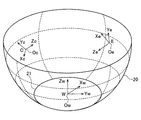
空間モデルは、図4に示すように、車両の下方の路面にほぼ一致する底部と、底部から立ち上がる壁部とを有するように形成する。 As shown in FIG. 4, the space model is formed so as to have a bottom portion that substantially matches the road surface below the vehicle and a wall portion that rises from the bottom portion.
空間モデルを地面の高さの水平面状の部分のみで構成すれば、地面上の白線を正確に再現できるが、この場合は自車両の周囲にある他の車両や木、建築物といった高さを持った対象物が大きく歪んで表示されてしまう。そのため、従来の例では、自車両及びその周辺では地面に対応した平面状であり、自車両から一定の水平距離でなだらかに壁状に立ち上がる椀型モデルが多く用いられている。椀型であると、対象物が立体物である場合に、壁面の立ち上がり角度が大きいほど実際の対象物の形状として認識しやすくなる。 If the space model is composed of only the horizontal surface of the ground level, the white line on the ground can be accurately reproduced. In this case, the height of other vehicles, trees, buildings around the vehicle The target object is displayed with large distortion. Therefore, in the conventional example, a saddle type model that has a flat shape corresponding to the ground in the host vehicle and its surroundings and rises gently from the host vehicle at a certain horizontal distance is used in many cases. If the object is a three-dimensional object, it becomes easier to recognize the actual shape of the object as the rising angle of the wall surface increases.
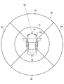
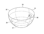
図3は椀型の空間モデル20の垂直断面を示し、図4は該空間モデル20を上方から見た図である。空間モデル20のうちの水平な、円形の部分21をモデルの底部、それ以外の部分をモデルの壁部と称する。椀型の空間モデル20はその底部の中心に自車両110が配置されるように形成される。壁部は、前方部分31、後方部分32、左側方部分33、及び右側方部分34を有する。前方部分31は、カメラ1aで撮像した前方撮像画像を貼り付けるための領域を構成し、後方部分32は、カメラ1bで撮像した後方撮像画像を貼り付けるための領域を構成し、左側方部分33は、カメラ1cで撮像した左側方撮像画像を貼り付けるための領域を構成し、右側方部分34は、カメラ1dで撮像した右側方撮像画像を貼り付けるための領域を構成する。
3 shows a vertical cross section of the saddle-shaped
撮像画像の空間モデルへの貼り付けは、実空間において対象物の画像をカメラで撮像することにより得られた、撮像面(撮像素子12の光電変換素子が配列された面)上の画像を、当該実空間に対応する仮想空間に配置された空間モデルへに投影することで行われる。このことを、図5〜図7を参照して説明する。
The pasting of the captured image to the space model is an image on the imaging surface (the surface on which the photoelectric conversion elements of the
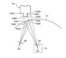
図5及び図6は、図4の空間モデルの領域31の、一定の高さ(図3に符号Hcで示す)における水平断面を、カメラ1aとともに示す。図5及び図6には対象物Osの同じ高さHcにおける水平断面が示されている。対象物Osとしては説明を簡単にするため、単純な形状のものが示されている。
5 and 6 show a horizontal section of the
図5は対象物Osが領域31よりも遠い場合を示し、図6は対象物Osの被撮像部分が領域31よりも近い場合を示す。いずれの場合にも、実空間における対象物Osの撮像画像はカメラ1aの撮像面CPに形成され、撮像面CPに形成された画像が仮想的に空間モデルの領域31に投影される。従って、対象物Osの符号Os01、Os02、Os03、Os04、Os05で示す点は、それぞれの点と、カメラ1aのレンズ中心Ocとを結ぶ直線と領域31との交点Ps01、Ps02、Ps03、Ps04、Ps05に投影される。
FIG. 5 shows a case where the object Os is farther than the
図7は、図4の空間モデルの領域31を一定の方位(図4に符号Vcで示す)における垂直断面を、カメラ1aとともに示す。図5及び図6について述べたのと同様に対象物Osの符号Os11、Os12で示す点は、それぞれの点と、カメラ1aのレンズの中心Ocとを結ぶ直線と領域31との交点Ps11、Ps12に投影される。
FIG. 7 shows a vertical section of the
以上は、空間モデルが対象物の被撮像面と異なる形状を有する場合、或いは異なる位置に形成された場合を想定している。空間モデルが対象物の被撮像面と同じ形状を有し、同じ位置に形成される場合には、実空間における対象物上のうちの被撮像面上の各点がそのまま仮想的に形成される空間モデルの対応する点となるが、この場合にも、カメラによる撮像により得られた画像が空間モデルに投影される。 The above assumes a case where the spatial model has a shape different from the surface to be imaged of the object, or is formed at a different position. When the space model has the same shape as the imaging surface of the object and is formed at the same position, each point on the imaging surface of the object in the real space is virtually formed as it is. In this case, an image obtained by imaging with the camera is projected onto the spatial model.
カメラ1aによる撮像により、対象物Osの各点のテクスチャ情報が、上記撮像面上の対応する位置の画素により取得されており、撮像画像が空間モデルへ投影変換される際、撮像面上の各画素から空間モデル上の対応する点へテクスチャ情報が貼り付けられる(マッピングされる)。
The texture information of each point of the object Os is acquired by the pixel at the corresponding position on the imaging surface by imaging with the
次に、空間モデル上の各点は、出力画像(仮想視点画像)内の位置を定義するスクリーン座標系Sの位置に対応付けられ、空間モデル上の各点のテクスチャ情報が、スクリーン座標系の対応する位置に貼り付けられ(マッピングされ)、これにより仮想視点画像(スクリーン座標系上の画像)が形成される。上記の対応付けにおいては、一例として図5に示すように、空間モデルと仮想視点の間にスクリーン座標系Sの平面(仮想視点画像面)SPを置き、空間モデルの各点と仮想視点Oeを結ぶ直線と、仮想視点画像面SPとの交点が、空間モデルの上記各点に対応する位置とされる。 Next, each point on the space model is associated with the position of the screen coordinate system S that defines the position in the output image (virtual viewpoint image), and the texture information of each point on the space model is A virtual viewpoint image (image on the screen coordinate system) is formed by being pasted (mapped) at a corresponding position. In the above association, as shown in FIG. 5 as an example, a plane (virtual viewpoint image plane) SP of the screen coordinate system S is placed between the space model and the virtual viewpoint, and each point of the space model and the virtual viewpoint Oe are set. Intersections between the connecting straight line and the virtual viewpoint image plane SP are positions corresponding to the above points of the space model.
以下、上記の投影変換で用いられる座標系について図8乃至図11を参照して説明する。
図8はカメラ1から入力される画像内の位置を定義するためのテクスチャ座標系T上の画像の一例を示す。図8には、自車両から前方を見た画像、即ち、カメラ1aで取得した画像が示されているが、他の方向を見た画像、即ち他のカメラ1b〜1dで取得した画像についても同様のテクスチャ座標系のデータが生成される。また、撮像画像が空間モデルに投影されると、空間モデルの各点に対応したテクスチャ座標系のデータが形成される。
Hereinafter, a coordinate system used in the above-described projection conversion will be described with reference to FIGS.
FIG. 8 shows an example of an image on the texture coordinate system T for defining the position in the image input from the
テクスチャ座標系Tは、横方向をx軸、縦方向をy軸とし、画像の大きさ(画素数)にかかわらず左下を(0、0)、右上端を(1、1)として、画像の任意の位置をパラメータとしてテクスチャを表す座標系である。
テクスチャ情報は、画像の各部乃至各画素の色(輝度、色相、彩度)を表す情報であり、各部乃至各画素の色を表す情報(テクスチャ値)が、テクスチャ座標系での座標位置に対応付けられている。
テクスチャ値は、テクスチャデータとして、投影変換部6のメモリ6a内の対応するアドレスに格納され、空間モデルへのテクスチャの貼り付けを行う際やスクリーン座標系Sで描画を行なう際に読み出されて利用される。
In the texture coordinate system T, the horizontal direction is the x-axis, the vertical direction is the y-axis, the lower left is (0, 0) and the upper right end is (1, 1) regardless of the image size (number of pixels). This is a coordinate system representing a texture using an arbitrary position as a parameter.
The texture information is information representing the color (brightness, hue, saturation) of each part or pixel of the image, and the information (texture value) representing the color of each part or pixel corresponds to the coordinate position in the texture coordinate system. It is attached.
The texture value is stored as texture data at a corresponding address in the
図9はスクリーン座標系Sの画像の一例を示す。図9に示される画像は自車両の後方から自車両をも含めて前方を見た画像である。自車両の画像としては予め用意されたイラスト画像或いは実画像が用いられる。図9のスクリーン座標系Sは、空間モデルが投影された画像の任意の位置をパラメータとして表す2次元座標系であり、横方向をx軸、縦方向をy軸とし、左下隅を(0、0)、右上隅を(1、1)として表す。 FIG. 9 shows an example of an image of the screen coordinate system S. The image shown in FIG. 9 is an image obtained by looking forward from the rear of the host vehicle including the host vehicle. An illustration image or a real image prepared in advance is used as the image of the host vehicle. The screen coordinate system S in FIG. 9 is a two-dimensional coordinate system that represents an arbitrary position of an image on which a spatial model is projected as a parameter. The horizontal direction is the x axis, the vertical direction is the y axis, and the lower left corner is (0, 0), and the upper right corner is represented as (1, 1).
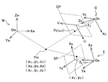
図10は空間モデルを構築する空間内の位置を定義する3次元のワールド座標系Wと、カメラ(のレンズ中心)の位置を原点Ocとして3次元位置を定義する撮像視点座標系Cと、仮想視点の位置を原点Oeとして3次元位置を定義する仮想視点座標系Eを示す。
撮像視点座標系CのZc軸は、カメラの光軸に一致する。仮想視点座標系EのZe軸は、仮想視点から空間モデルを見るときの視線の方向に一致する。
FIG. 10 shows a three-dimensional world coordinate system W that defines a position in a space for constructing a space model, an imaging viewpoint coordinate system C that defines a three-dimensional position with the position of the camera (center of the lens) as an origin Oc, and a virtual A virtual viewpoint coordinate system E that defines a three-dimensional position with the viewpoint position as the origin Oe is shown.
The Zc axis of the imaging viewpoint coordinate system C coincides with the optical axis of the camera. The Ze axis of the virtual viewpoint coordinate system E coincides with the direction of the line of sight when viewing the space model from the virtual viewpoint.
以下、撮像画像から空間モデルへの投影変換についてより詳しく説明する。
図11は、図10に示される座標系C、W、Eの相互関係を示すとともに、カメラの撮像面CP及び仮想視点の画像を形成する面(仮想視点画像面)SPを示す。
カメラにより、視点OcからZc軸の方向を見て撮像することで得られた画像は、撮像面CP(光電変換素子が配列された面)上にあるものと考えることができる。撮像面は実際には、視点座標系の原点(レンズの中心)Ocに対して撮像対象物とは反対の側にあるが、便宜上同じ側に示されている。
一方、任意の(所望の)仮想視点Oeから任意の(所望の)方向Zeを見た画像は、仮想視点画像面SP上に形成されるものと考えることができる。
撮像面CP上の二次元座標は(u,v)で表され、仮想視点画像面SP上の座標は(xS,yS)で表されている。
Hereinafter, projection conversion from a captured image to a spatial model will be described in more detail.
FIG. 11 shows the interrelationship between the coordinate systems C, W, and E shown in FIG. 10, and the imaging plane CP of the camera and a plane (virtual viewpoint image plane) SP that forms a virtual viewpoint image.
It can be considered that an image obtained by capturing an image while viewing the direction of the Zc axis from the viewpoint Oc with the camera is on the imaging surface CP (surface on which photoelectric conversion elements are arranged). The imaging surface is actually on the side opposite to the imaging target with respect to the origin (lens center) Oc of the viewpoint coordinate system, but is shown on the same side for convenience.
On the other hand, an image obtained by viewing an arbitrary (desired) direction Ze from an arbitrary (desired) virtual viewpoint Oe can be considered to be formed on the virtual viewpoint image plane SP.
Two-dimensional coordinates on the imaging plane CP are represented by (u, v), and coordinates on the virtual viewpoint image plane SP are represented by (x S , y S ).
撮像面CP上の位置Pcの座標(u,v)と、原点Ocとを結ぶ線と、空間モデルを構成する面との交点Pmの、撮像視点座標系Cの座標(xC,yC,zC)との間には以下の関係がある。

式(1a)、(1b)により、撮像面上の各画素の位置と、空間モデル上の各点とが対応付けられ、この対応関係に基づいて、それぞれの画素で得られたテクスチャを、空間モデル上の対応する位置に割り当てることができる。
The coordinates (x C , y C , X) of the imaging viewpoint coordinate system C of the intersection point Pm between the line connecting the coordinates (u, v) of the position Pc on the imaging plane CP and the origin Oc and the plane constituting the spatial model. z C ) has the following relationship.
By the expressions (1a) and (1b), the position of each pixel on the imaging surface and each point on the space model are associated with each other, and based on this correspondence relationship, the texture obtained by each pixel is expressed as a space. Can be assigned to the corresponding position on the model.
図10及び図11には撮像視点座標系Cが1つだけ示されているが、実際には、撮像視点座標系Cはカメラの数だけ存在する。
複数の撮像画像の画素が空間モデルの同じ点に対応付けられる場合には、予め定めた規則に従って、いずれかの撮像画像の画素を優先的に選択して、選択した撮像画像の画素のテクスチャを付与する。
例えば空間モデルの領域毎に優先するカメラを予め決めておくこととしても良い。例えば、空間モデルの前方の領域31については前方を撮像しているカメラ1aの撮像画像を優先させ、空間モデルの後方の領域32については後方を撮像しているカメラ1bの撮像画像を優先させ、空間モデルの左側方の領域33については左側方を撮像しているカメラ1cの撮像画像を優先させ、空間モデルの右側方の領域34については右側方を撮像しているカメラ1dの撮像画像を優先させる。
そのように一つのカメラの画素を選択する代わりに、複数のカメラの画素についてテクスチャを重み付け平均することにより、空間モデル上の対応位置のテクスチャを定めることとしても良い。
Although only one imaging viewpoint coordinate system C is shown in FIGS. 10 and 11, there are actually as many imaging viewpoint coordinate systems C as the number of cameras.
When pixels of a plurality of captured images are associated with the same point of the spatial model, one of the captured image pixels is preferentially selected in accordance with a predetermined rule, and the texture of the selected captured image pixel is determined. Give.
For example, a camera that has priority for each area of the space model may be determined in advance. For example, priority is given to the captured image of the
Instead of selecting the pixels of one camera in this way, the textures at the corresponding positions on the spatial model may be determined by weighting and averaging the textures of the pixels of a plurality of cameras.
空間モデルのうち、いずれのカメラの画素とも対応付けられない部分(位置)には、予め定められたテクスチャ情報、例えば色が黒であることを示す情報を付与する。 A predetermined texture information, for example, information indicating that the color is black is assigned to a portion (position) that is not associated with any camera pixel in the spatial model.
空間モデルとしては、一般には、3角形のポリゴンの集合として構築されたものが用いられる。この場合、各ポリゴンの頂点に対して、第1から第4までのカメラ1a〜1dのいずれによる撮像で得られたテクスチャを割り当てるかを決定し、決定結果に基づいて、各頂点へのテクスチャ情報の割り当てを行う。
As the spatial model, a model constructed as a set of triangular polygons is generally used. In this case, it is determined which of the first to
空間モデルが予め定められた形状を有するものである場合には、空間モデルの各点の位置を表す情報、或いは各点の位置の算出に必要な情報が予めメモリ6aに記憶されている。空間モデルが対象物までの距離に応じて形成されるものであれば、空間モデルが形成される際に、空間モデルの各点の位置を表す情報が算出され、メモリ6aに記憶される。
When the spatial model has a predetermined shape, information indicating the position of each point of the spatial model or information necessary for calculating the position of each point is stored in the
撮像視点座標系Cの座標(xC,yC,zC)と、ワールド座標系Wの座標(xW,yW,zW)との間には、下記の式(2)で表される関係がある。
ACWは、撮像視点座標系をワールド座標系の向きに合わせるための3行3列の回転行列であり、仮想空間内でのカメラ視点の位置姿勢から算出される。
The coordinates (x C , y C , z C ) of the imaging viewpoint coordinate system C and the coordinates (x W , y W , z W ) of the world coordinate system W are expressed by the following equation (2). There is a relationship.
A CW is a 3-by-3 rotation matrix for aligning the imaging viewpoint coordinate system with the orientation of the world coordinate system, and is calculated from the position and orientation of the camera viewpoint in the virtual space.
上記の式(2)を用いて、空間モデルの各点の撮像視点座標系Cの座標をワールド座標系Wの座標に変換することができる。 The coordinates of the imaging viewpoint coordinate system C of each point of the space model can be converted into the coordinates of the world coordinate system W using the above equation (2).
ワールド座標系Wの座標(xW,yW,zW)と仮想視点座標系Eの座標(xE,yE,zE)との間には、下記の式(3)で表される関係がある。
AWEは、ワールド座標系の向きを仮想視点座標系の向きに合わせるための3行3列の回転行列であり、仮想空間内での仮想視点の位置姿勢から算出される。
The coordinates (x W , y W , z W ) of the world coordinate system W and the coordinates (x E , y E , z E ) of the virtual viewpoint coordinate system E are expressed by the following expression (3). There is a relationship.
A WE is a 3-by-3 rotation matrix for matching the orientation of the world coordinate system with the orientation of the virtual viewpoint coordinate system, and is calculated from the position and orientation of the virtual viewpoint in the virtual space.
上記の式(3)を用いて、空間モデルの各点のワールド座標系Wの座標を仮想視点座標系Eの座標に変換することができる。 Using the above equation (3), the coordinates of the world coordinate system W of each point of the space model can be converted into the coordinates of the virtual viewpoint coordinate system E.
空間モデル上の各位置を表す仮想視点座標系の座標(xE,yE,zE)からスクリーン座標系の座標(xS,yS)への変換は以下の式(4)で表される。
以上のようにして得られたスクリーン座標系Sの画像を構成する画素の各々に対して、空間モデルに対応して形成されたテクスチャ座標系のテクスチャを対応付け、描画を行う。このような処理により、任意の視点から任意の方向を見た画像(スクリーン座標系の画像)が得られる。 The texture coordinate system texture formed corresponding to the spatial model is associated with each pixel constituting the image of the screen coordinate system S obtained as described above, and drawing is performed. By such processing, an image (screen coordinate system image) in which an arbitrary direction is viewed from an arbitrary viewpoint is obtained.
空間モデルがポリゴンの集合で構築されている場合には、ポリゴンの各頂点に対応する、スクリーン座標系S上の位置が求められ、求められた位置に、対応するテクスチャ座標系上の位置(xT,yT)の色の情報を複写し、頂点に対応する画素以外の画素については、補間によりテクスチャ値を求めて付与する。 When the spatial model is constructed by a set of polygons, the position on the screen coordinate system S corresponding to each vertex of the polygon is obtained, and the corresponding position on the texture coordinate system (x T , y T ) color information is copied, and for pixels other than the pixel corresponding to the vertex, a texture value is obtained by interpolation and assigned.
上記の例では、テクスチャ情報が、撮像面から空間モデルの対応する点に付与され、空間モデルから仮想視点画像の対応する点に付与されるが、撮像面から空間モデルへの投影変換の際には、空間モデルの各点に、撮像面の対応する位置、従ってテクスチャ座標系の座標を表す情報のみを参照情報として対応付け、空間モデルからスクリーン座標系の画像への投影変換の際に、空間モデルの各点に対応付けられている参照情報を、スクリーン座標系の対応する点に複写し、スクリーン座標系において描画を行う際に、参照情報で指定される、テクスチャ座標系の座標で表される位置からテクスチャ情報を取得してテクスチャを貼り付けることとしても良い。 In the above example, texture information is given to the corresponding point of the spatial model from the imaging plane, and is given to the corresponding point of the virtual viewpoint image from the spatial model, but at the time of projection conversion from the imaging plane to the spatial model Is associated with each point of the space model as a reference information only for the corresponding position on the imaging surface, and thus the information representing the coordinates of the texture coordinate system, and when projecting from the space model to the image of the screen coordinate system, When the reference information associated with each point in the model is copied to the corresponding point in the screen coordinate system and rendered in the screen coordinate system, it is represented by the coordinates in the texture coordinate system specified by the reference information. It is also possible to obtain texture information from the position to be attached and paste the texture.
このような構成においては、空間モデルがポリゴンの集合で構築されている場合には、各ポリゴンの各頂点に対して、第1から第4までのカメラ1a〜1dのいずれによる撮像で得られた画像のどの画素を割り当てるかを決定し、割り当てられた画素を含む画像(或いは該画像を撮像したカメラ)を示す情報、及び当該画像内における割り当てられた画素の位置、即ち対応するテクスチャ座標内の座標を保持させる。そして、スクリーン座標系の画像の形成に当たっては、ポリゴンの各頂点に対応するスクリーン座標系Sの各画素に、対応するテクスチャ座標系上の位置(xT,yT)の色の情報を複写し、頂点に対応する画素以外の画素については、補間によりテクスチャ値を求めて付与する。
In such a configuration, when the space model is constructed of a set of polygons, the image is obtained by any one of the first to
この場合、スクリーン座標系Sの各画素に、複数のテクスチャ座標系の座標が対応付けられている場合には、複数のテクスチャ座標系の対応する座標のテクスチャ情報の何れか一つの選択、或いは重み付け平均を行って、貼り付けるテクスチャを決めることになる。 In this case, when coordinates of a plurality of texture coordinate systems are associated with each pixel of the screen coordinate system S, selection or weighting of any one of the texture information of the corresponding coordinates of the plurality of texture coordinate systems The average is done to determine the texture to paste.
なお、合成画像(画像表示部80で表示される画像)にカメラのレンズの収差の影響が現れないようにするため、歪みを補正したテクスチャ座標をモデルの頂点に与えることとしても良い。そうすることにより、合成時には歪みを補正するための計算は不要となり、カメラから取得した画像をそのまま適用しさえすればレンズ収差の影響が除去された合成画像を得ることができる。 In order to prevent the influence of the aberration of the camera lens from appearing in the composite image (the image displayed on the image display unit 80), the texture coordinates corrected for distortion may be given to the vertex of the model. By doing so, a calculation for correcting distortion is not required at the time of synthesis, and a composite image from which the influence of lens aberration is removed can be obtained by applying the image acquired from the camera as it is.
画像合成部7はこのようなスクリーン座標系の画像の一部又は全部を抽出して、必要に応じて拡大、縮小、回転を行い、表示画面内での位置を決め、さらに必要に応じて他の画像を組合せることで表示用の画像を形成する。 The image synthesizing unit 7 extracts part or all of the image in such a screen coordinate system, performs enlargement, reduction, and rotation as necessary, determines the position in the display screen, and further others as necessary A display image is formed by combining these images.
例えば自車両の上方から見下ろした画像を生成する場合には、自車両のイラスト画像を中央に表示し、その周辺(前後左右)に、路面の画像を表示するように、スクリーン座標系の画像を加工する。一方、車両から後方を見た画像を生成する場合には、自車両のイラスト画像を表示せず、カメラで得た撮像画像のみを表示するように、スクリーン座標系の画像を加工する。 For example, when generating an image looking down from above the host vehicle, an illustration image of the host vehicle is displayed in the center, and an image of the screen coordinate system is displayed so that a road surface image is displayed in the periphery (front, rear, left and right). Process. On the other hand, when generating an image viewed from behind the vehicle, the image of the screen coordinate system is processed so that only the captured image obtained by the camera is displayed without displaying the illustration image of the own vehicle.
図9は、以上の処理を行った結果形成される、スクリーン座標系の画像の一例を示すものである。図9に示す例では、自車両110の後方から前方を見たときの画像であり、曲線131で囲まれた部分は、空間モデルの領域31に投影された画像部分に対応し、曲線133で囲まれた部分は、空間モデルの領域33に投影された画像部分に対応し、曲線134で囲まれた部分は、空間モデルの領域34に投影された画像部分に対応し、曲線121で囲まれた部分は、空間モデルの底部21に投影された画像部分に対応する。
画像部分131と画像部分133のつなぎ目部分が符号40aで示され、画像部分131と画像部分134のつなぎ目部分が符号40bで示されている。
FIG. 9 shows an example of an image in the screen coordinate system formed as a result of the above processing. In the example illustrated in FIG. 9, the image is a front view of the
A joint part between the
どの視点からどの方向を見た画像をスクリーン座標系の画像として生成するかは、自車両の状態(進行方向、進行速度)によって自動的に切り換えることとしても良く、ユーザが選択可能としても良い。
例えば、駐車のため後進する場合には、自車両から後方を見た画像、或いは自車両の上方から見下ろした画像の表示が望まれることが多い。この場合、自車両状態検出部90の出力に基づいて後進していることを検出し、後方を見た画像或いは上方から見下ろした画像が自動的に選択されるようにしておき、ユーザが操作部92の操作で他の画像に切り換えることも可能であるようにしておくことが考えられる。
Whether to generate an image viewed in which direction from which viewpoint as an image in the screen coordinate system may be automatically switched according to the state (traveling direction, traveling speed) of the host vehicle, or may be selectable by the user.
For example, when moving backward for parking, it is often desired to display an image viewed from behind the host vehicle or an image viewed from above the host vehicle. In this case, it is detected that the vehicle is moving backward based on the output of the own vehicle
仮想視点の切り換えは、投影変換部6における投影変換において、仮想視点座標系の原点を変更することで実現できる。
仮想視点は、予め用意されたもののうちのいずれかを選択するようにしてもよく、一旦予め用意されたもののうちのいずれかを自動的に選択した後に、ユーザが操作部92を操作することで調整が可能なようにしても良い。
仮想視点の位置の変更は、上記したワールド座標系Wの原点Owに対する仮想視点座標系Eの原点Oeの相対位置(tex,tey,tez)の変更により行われ、仮想視点からの向きの変更は、仮想視点座標系EのZe軸の方向の変更により行われる。
Switching of the virtual viewpoint can be realized by changing the origin of the virtual viewpoint coordinate system in the projection conversion in the projection conversion unit 6.
The virtual viewpoint may be selected from any one prepared in advance, and after the user automatically selects any one prepared in advance, the user operates the operation unit 92. Adjustment may be possible.
The change of the position of the virtual viewpoint is performed by changing the relative position (tex, tey, tez) of the origin Oe of the virtual viewpoint coordinate system E with respect to the origin Ow of the world coordinate system W described above. This is performed by changing the direction of the Ze axis of the virtual viewpoint coordinate system E.
先にも述べたように、本発明では、予め定められた形状の空間モデルの代わりに、自車両からの対象物の各部までの距離に応じた形状の空間モデルに対象物の画像を投影する。
以下、このことを図12〜図15を参照して説明する。
図12は、図5と同じ位置の水平断面図であり、対象物Osとカメラ1aが示されている。
As described above, in the present invention, instead of a space model having a predetermined shape, an image of the object is projected onto a space model having a shape corresponding to the distance from the host vehicle to each part of the object. .
Hereinafter, this will be described with reference to FIGS.
FIG. 12 is a horizontal cross-sectional view at the same position as in FIG. 5 and shows the object Os and the
但し、図5の空間モデルの領域31は図12には示されていない。本発明では、空間モデルの領域31の代わりに、対象物Os1のうち、カメラ1aで撮像された面(実線で示す)Os1sを空間モデルの一部とする。対象物Os1のうち、他の部分に隠れる部分(点線で示す)Os1hは空間モデルの一部とはならず、隠れる部分の両端を結ぶ線(鎖線で示す)Os1cが空間モデルの一部となる。
図示のように別の対象物Os2が同時に撮像されている場合、その被撮像面Os2sもまた空間モデルの一部となる。
However, the
As shown in the figure, when another object Os2 is simultaneously imaged, the imaged surface Os2s is also a part of the spatial model.
なお、以上は、カメラ1aで撮像される面の全体について、距離センサによる距離測定の結果距離情報が取得できたことを条件としている。カメラ1aで撮像された面のうち、距離情報が取得できなかった領域には空間モデルを構成しないこととしても良く、その周囲の部分に基づいて形成された空間モデル部分に基づいて補間により対応する空間モデル部分を形成しても良い。例えば図12に示すように、対象物Os1、Os2の間の領域において、自車両からの距離情報が得られなかった場合、鎖線Oscで示すように、自車両から所定の距離において、対象物Os1、Os2間を接続する面を構成しても良い。
The above is based on the condition that distance information can be acquired as a result of distance measurement by the distance sensor for the entire surface imaged by the
図13(a)及び(b)は、図12とは異なる対象物を撮像した場合の、空間モデル生成の例を示す。図13(a)は、カメラ1aで前方の他の車両120を撮像している状態を示す立面図である。この場合も図12を参照して説明したのと同様に、対象物としての車両120の特定の位置、例えばカメラ1aから対象物の各部分までの距離に応じた空間モデル51(図13(b))を形成する。図13(b)には、形成される空間モデル51の垂直断面が示されている。
FIGS. 13A and 13B show examples of spatial model generation when an object different from that shown in FIG. 12 is imaged. FIG. 13A is an elevation view showing a state in which another
図13(a)に示す例では、車両120の荷台120aから飛び出ている荷物50の突出端50bが自車両(カメラ1a)に最も近く、その距離はL50bと算出されている。自車両が車両120の方向に進行している場合、最も気を付けるべきは荷物50の突出部分(自車両に向けて突出した部分)50aであるが、予め定められた椀型の空間モデルに投影した画像では荷物50が突出部分50aを有することは認識しにくい。そのため、画像表示部80に表示される画像を頼りに運転すると荷物50の突出部分50aに衝突してしまうおそれがある。
In the example shown in FIG. 13A, the
本実施の形態では、荷物50の突出部分50a、特にその突出端50bまでの距離が認識しやすいようにするため、予め定められた空間モデルではなく、距離情報生成部10で生成した距離情報を基にモデル形状決定部4で生成した、自車両から対象物の各部までの距離に応じた形状(従って、対象物の被撮像面の形状に応じた形状)の空間モデル51を使用する(図13(b))。この空間モデル51は、荷物50の突出部分50aに対応した突出部分51aを有し、その突出端51bは、荷物の突出端50bに対応した位置に形成される。
In the present embodiment, in order to make it easy to recognize the distance to the protruding
このような空間モデル51を用いて形成した画像(画像表示部80に表示される画像)の一例を図14に示す。また、比較のため、従来の椀型の空間モデルを用いて形成した画像を図15に示す。これらの図で、画像中の各部は、対応する対象物のそれぞれの部分と同じ符号で示されている。
図15では、椀型の空間モデルへの投影の結果、画像に歪みが生じ(押しつぶされた画像となっており)、遠近感が失われているのに対して、図14では、歪みがなく遠近感のある画像が得られている。このため、荷物50の突出部分50aが確認しやく、荷物50の突出部分50aへの衝突の危険が認識しやすい。
An example of an image (an image displayed on the image display unit 80) formed using such a space model 51 is shown in FIG. For comparison, FIG. 15 shows an image formed using a conventional saddle type space model. In these figures, each part in the image is indicated by the same reference numeral as each part of the corresponding object.
In FIG. 15, as a result of projection onto the saddle-shaped space model, the image is distorted (a crushed image) and the perspective is lost, whereas in FIG. 14, there is no distortion. An image with a sense of perspective is obtained. For this reason, it is easy to recognize the protruding
以上のように、本実施の形態においては、予め定められた椀型の空間モデルを使わずに、自車両から対象物の各部までの距離に対応した形状の空間モデルを用いるため、任意の視点位置から自車両周辺を見た合成画像を生成する際に、自車両近辺にある対象物が押しつぶされたように映ることがなく、対象物の凹凸、特に手前への突出部分を認識しやすい画像が形成されるため、衝突防止に役立つ。 As described above, in this embodiment, since a space model having a shape corresponding to the distance from the host vehicle to each part of the object is used without using a predetermined saddle-shaped space model, an arbitrary viewpoint is used. When generating a composite image that looks at the periphery of the host vehicle from the position, the object in the vicinity of the host vehicle does not appear to have been crushed, and it is easy to recognize the unevenness of the target object, especially the protruding part toward you Is formed, which helps prevent collisions.
なお、上記の実施の形態では、図13(b)を参照して説明したように、距離情報生成部10で生成した距離情報を基に、自車両から対象物の各部までの距離に応じた形状の空間モデルを形成する場合に、空間モデル形成のための計算量が極めて多くなることがある。モデル形状決定部4を構成する演算処理装置の演算能力が高い場合はよいが、演算能力が低い演算処理装置を用いている場合は演算負荷を減らす必要がある。
In the above embodiment, as described with reference to FIG. 13B, the distance information generated by the distance
そこで、複数の対象物のうちの、自車両に最も近い対象物、或いは当該対象物のうちの自車両に最も近い部分(対象物部分)、例えば、自車両の進行方向に位置する対象物の自車両に最も近い部分のみについて距離を考慮した形状とし、他の部分(及び他の対象物)については予め定められた形状、例えば椀型の空間モデルを用いることも考えられる。自車両の進行方向についての情報は、自車両状態検出部90から得られる。上記の予め定められた形状、例えば椀型の空間モデル形状を表すデータは、予めモデル形状決定部4内のメモリ4aに記憶されており、上記「他の部分」のためのモデルの形状の決定の際に、この記憶データが利用される。このようにすることで、計算量を削減しつつ、衝突回避のための安全性向上を図ることができる。
Therefore, among the plurality of objects, the object closest to the own vehicle, or a part of the object closest to the own vehicle (object part), for example, an object located in the traveling direction of the own vehicle It is also conceivable to use a shape that takes distance into consideration only for the portion closest to the host vehicle and to use a predetermined shape, for example, a saddle type space model, for the other portions (and other objects). Information about the traveling direction of the host vehicle is obtained from the host vehicle
対象物が図13(a)に示される他の車両である場合に、自車両に最も近い部分のみについて距離を考慮に入れた形状の空間モデルの一例を図13(c)に示す。図13(c)は、図13(b)と同様に、空間モデル52の垂直断面を示している。
空間モデル52のうち、符号52aで示す部分は、自車両110から他の車両120の荷物50のうちの手前に突出した部分50aの各部までの距離に対応しており、それ以外の部分は椀型の形状を有する。
FIG. 13C shows an example of a spatial model having a shape in which the distance is taken into consideration only for the portion closest to the host vehicle when the object is another vehicle shown in FIG. FIG.13 (c) has shown the vertical cross section of the
Of the
図示の例では、車両120の荷台120aの後端120bまで(後端120b及びそれよりも前の部分)は突出した部分とはされず、荷物50のうちの荷台120aの後端120bから後方に突出した部分50aのみが突出した部分(自車両に最も近い部分)として扱われ、空間モデル52には、この部分50aに対応した形状の部分52aが形成されている。
突出部分52aの突出端52bは、自車両から荷物50の突出端50b(自車両に最も近い側の端部)までの距離L50bに対応した位置に形成される。
空間モデル52のうちの部分52a以外の部分は、部分52aに連続した形状となるように、形成される。即ち、底部52dの半径21a、壁部52cの曲率等は、突出部分52aの位置(自車両からの距離)に基づいて決定される。
In the illustrated example, the
The
Parts of the
上記のような空間モデルを用いて形成した表示画像の一例を図16に示す。図16では、突出部分50a以外は図15と同様であるが、突出部分50aのみ、図14と同様に、歪みがなく、遠近感のある画像が得られている。このため、荷物50の突出部分50aが確認しやすい。
An example of the display image formed using the above space model is shown in FIG. 16 is the same as FIG. 15 except for the protruding
また、突出部分52aの突出量は、荷物の突出部分50aに一致していなくても良く、例えば予め定めた長さ以下に制限しても良い。
Further, the protruding amount of the protruding
さらに、対象物の突出部分ととともにその周囲の部分に対応する部分については距離を考慮に入れた形状とし、その他の部分を予め定められた椀型の空間モデルを形成することとしても良い。この場合の空間モデルの全体形状は、図17に示すごとくとなり、この場合の表示画像の例は図18に示すごとくとなる。 Further, the portion corresponding to the surrounding portion together with the protruding portion of the object may be shaped in consideration of the distance, and the other portion may be formed as a predetermined saddle-shaped space model. The overall shape of the space model in this case is as shown in FIG. 17, and an example of the display image in this case is as shown in FIG.
図17では、空間モデルの底部、前方領域、後方領域、左側方領域及び右側方領域に図4の同様の部分と同じ符号が付してある。前方領域31の一部に対応する位置に、対象物の突出部分が検出された結果、当該一部及びその周辺から成る範囲36のみ、自車両から対象物の各部までの距離に対応した形状とされている。上記の範囲36に投影された画像が、画像表示部80では図18において枠54で囲んだ部分となる。
In FIG. 17, the same reference numerals as those in FIG. 4 are assigned to the bottom, front region, rear region, left side region, and right side region of the space model. As a result of detecting the protruding portion of the object at a position corresponding to a part of the
図18において枠54の外部は図15と同様の画像が形成され、枠54の内部には、図14と同様の画像が形成されている。このような画像であっても、荷物50の突出部分50aが確認しやすい。
なお、枠54の内部と外部との画像の不連続性が目立つのを避けるため、境界部分をぼかすための画像処理を行なっても良く、逆に枠の内部のみ表示色を変えることで違いを強調して、危険に注意を喚起することとしても良い。
In FIG. 18, an image similar to FIG. 15 is formed outside the frame 54, and an image similar to FIG. 14 is formed inside the frame 54. Even in such an image, the protruding
In addition, in order to avoid the discontinuity of the image between the inside and the outside of the frame 54, image processing for blurring the boundary portion may be performed, and conversely, the difference can be made by changing the display color only inside the frame. It may be emphasized to call attention to danger.
図13(c)の例では、荷台120aの後端120bまでを、対象物のうちの自車両に向けて突出した部分(即ち自車両に最も近い部分)として処理しているが、自車両に最も近い対象物又はその部分のうちの自車両に最も近い端部50bから所定の範囲、例えば1m前方(遠方)までを自車両に最も近い部分として扱っても良い。
In the example of FIG. 13 (c), the portion up to the
また、どの範囲までを、自車両に向けて突出した部分(自車両に最も近い部分)として処理するかを、予め設定可能としても良く、自車両の状態、例えば進行方向、進行速度に基づいて自動的に切り換えることとしても良く、ユーザが表示画像を見ながら調整可能としても良い。
同様に、空間モデルの各部の寸法(底部52dの半径21a、壁部52cの曲率等)もユーザが予め任意に設定可能としても良く、ユーザが表示画像を見ながら調整可能としても良い。
In addition, it may be possible to set in advance which range is processed as a portion protruding toward the own vehicle (the portion closest to the own vehicle), based on the state of the own vehicle, for example, the traveling direction and the traveling speed. Switching may be performed automatically, or the user may be able to adjust while viewing the display image.
Similarly, the dimension of each part of the space model (the
さらにまた、対象物までの距離が所定の閾値よりも近い場合にのみ、空間モデルの形状を対象物の各部までの距離に応じたものとすることとしても良い。また、上記の所定の閾値を、自車両の進行方向、進行速度に応じて変化させることしても良い。さらにまた、所定の方向、例えば後方の領域のみ、空間モデルの形状を対象物の各部までの距離に応じた形状とし、他の方向では、予め定められ形状、例えば椀型の形状としても良い。 Furthermore, only when the distance to the object is closer than a predetermined threshold value, the shape of the spatial model may be set according to the distance to each part of the object. Further, the predetermined threshold value may be changed according to the traveling direction and traveling speed of the host vehicle. Furthermore, the shape of the space model may be a shape corresponding to the distance to each part of the object only in a predetermined direction, for example, the rear region, and may be a predetermined shape, for example, a bowl shape, in the other directions.
なお、底部の形状を円形として説明してきたが、楕円でもよく、ユーザが任意の値に決定することが出来る。例えば、楕円の内部に引いた2焦点を通る線分を長径、長径の垂直二等分線を楕円の内部に引いた線分を短径と定義し、これらの値をユーザが設定することで空間モデルの底部の形状を決めることができる。 Although the bottom portion has been described as a circular shape, it may be an ellipse, and the user can determine an arbitrary value. For example, a line segment passing through two focal points drawn inside an ellipse is defined as a major axis, a line segment obtained by drawing a vertical bisector of a major axis inside an ellipse is defined as a minor axis, and these values are set by the user. The shape of the bottom of the space model can be determined.
なおまた、上記の「予め定められた形状」は椀型に限定されず、例えば円柱型であっても良く、四角柱型であっても良い。さらに前後左右のうちの選択された方向、例えば一方又は二方にのみ壁部を設けた形状(衝立型)であっても良い。さらに、いずれの場合にも、底部は、路面の画像の形成が必要なとき以外は省略しても良い。 The “predetermined shape” is not limited to a saddle shape, and may be, for example, a cylindrical shape or a quadrangular prism shape. Furthermore, the shape (partition type | mold) which provided the wall part only in the direction selected among front and back, right and left, for example, one or two sides may be sufficient. Further, in any case, the bottom may be omitted except when it is necessary to form an image of the road surface.
また、図9の点線で囲んだ領域40はスクリーン座標系における画像の境界部を示しているが、この境界部のずれにより本来見える筈の画像が見えなくなる(死角が発生する)ことがある。死角の発生を防ぐために、画像間の境界部においては隣接する二つの画像を、係数(アルファ値)を使って半透明合成(アルファブレンド)することにより結合してもよい。このように処理することにより画像間の境界が目立ちにくくなるだけでなく、死角をなくすことにより視認性が向上する。 Further, an area 40 surrounded by a dotted line in FIG. 9 indicates the boundary portion of the image in the screen coordinate system. However, due to the shift of the boundary portion, the originally visible eyelid image may not be seen (a blind spot occurs). In order to prevent the generation of blind spots, two adjacent images may be combined at the boundary between the images by semi-transparent composition (alpha blend) using a coefficient (alpha value). This processing not only makes the boundary between images less noticeable, but also improves visibility by eliminating blind spots.
なおまた、上記の説明において、カメラ1で撮像した対象物の画像の全体について距離情報を得ることができる旨述べたが、このことは、必ずしも撮像した画像の各画素について個別に距離測定を行うことを意味しない。一般にセンシング部2によるセンシングの分解能はカメラ1による撮像の分解能よりも低いので、距離情報は、複数の画素ごとに1つしか得られない。この場合、複数の画素ごとに得られた距離情報を当該複数の画素に対して共通の距離情報として用いても良く、当該複数の画素のうちの距離情報が得られた角度に最も近い画素についての距離情報として用いて、他の画素については、補間演算により距離情報を求めても良い。
In addition, in the above description, it has been described that the distance information can be obtained for the entire image of the object captured by the
また、センシング部2として用いるソナーセンサの走査範囲は、カメラ1の画角ほど広くないため、カメラ1で撮像した画像に映っている対象物すべてに超音波を放射するのは困難である。そのため、例えばセンシング部2の各々を複数のソナーセンサで構成し、複数のソナーセンサの角度をずらして配置することでカメラ1aの画角すべてを放射範囲とすることも可能である。そのように構成することでカメラ1で撮像した対象物が画像内のどこに映っていても距離情報生成部10で対象物についての距離情報が得られることになり、衝突防止の観点から有効である。
Further, since the scanning range of the sonar sensor used as the sensing unit 2 is not as wide as the angle of view of the
さらにまた、自車両周辺の対象物までの距離測定をセンシング部2のみで行わずに、カメラのみを使用した距離測定とセンシング部2を使用した距離測定の組合せとしてもよい。
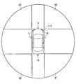
図19は説明を容易にするために椀型の空間モデルを使用したときの車両上方からみた図を示している。第1乃至第4のカメラ1a〜1dの各々が180度の画角をもつ魚眼レンズを備えている場合、領域60内に存在する対象物は第1のカメラ1aと第4のカメラ1dの双方で撮像可能であるため、これら2台のカメラを使用したパッシブステレオ法により対象物までの距離測定が可能である。同様に、領域61についてはカメラ1bとカメラ1d、領域62についてはカメラ1bとカメラ1c、領域63についてはカメラ1aとカメラ1cを使用した対象物までの距離測定が可能である。さらにカメラを使うため、高分解能の距離測定が可能である。
Furthermore, the distance measurement using only the camera and the distance measurement using the sensing unit 2 may be performed without measuring the distance to the object around the host vehicle only by the sensing unit 2.
FIG. 19 shows a view from above the vehicle when a saddle type space model is used for easy explanation. When each of the first to
図19における領域60〜63以外の領域にある対象物についてはセンシング部2で得られるデータを基に距離を測定する必要があるが、画角すべてを漏れなくセンシングデバイスの検知対象範囲とする場合に比べ、センシングデバイスの数を削減することができるためコストを低減できる。
For objects in areas other than the
さらに、センシング部2をセンシングデバイスではなく、LEDやレーザを光源として対象物にスリット光や2次元のパターンを投射する投光器により構成してもよい。その場合はアクティブステレオ方式により、カメラ1で撮像した画像から三角測量の原理で距離を得ることができる。
Furthermore, you may comprise the sensing part 2 with the light projector which projects not only a sensing device but a slit light and a two-dimensional pattern on a target object using LED and a laser as a light source. In that case, the distance can be obtained from the image captured by the
以上本発明を、画像処理装置として説明したが、画像処理装置により実施される画像処理方法も本発明の一部を成し、該画像処理装置の機能をコンピュータに実行させ、或いは上記画像処理方法をコンピュータに実行させるためのコンピュータプログラム、及び該コンピュータをコンピュータにより読み取り可能な形で記憶した記録媒体もまた本発明の一部を成す。 Although the present invention has been described above as an image processing apparatus, an image processing method implemented by the image processing apparatus also forms part of the present invention, and allows a computer to execute the functions of the image processing apparatus. A computer program for causing a computer to execute and a recording medium storing the computer in a form readable by the computer also form a part of the present invention.
1a〜1d カメラ、 2a〜2d センシング部、 3 距離情報算出部、 4 モデル形状決定部、 5 カメラ制御部、 5a 輝度調整部、 5b カメラパラメータ設定部、 6 投影変換部、 7 画像合成部、 8 情報伝達部、 9 データバス、 11 光学系、 12 撮像素子、 13 AD変喚器、 20 空間モデル、 21 空間モデルの底部、 10 距離情報生成部、 31、32、33、34 空間モデルの壁部、 50 荷物、 50a 突出部分、 50b 突出部分の突出端、 51、52、53 空間モデル、 51a、52a、53a 空間モデルの突出部分、 51b、52b、53b 突出部分の突出端、 52c、53c 空間モデルの壁部、 80 画像表示部、 82 スピーカ、 90 自車両状態検出部、 92 操作部、 100 画像処理装置、 110 自車両、 120 他の車両。
1a to 1d camera, 2a to 2d sensing unit, 3 distance information calculation unit, 4 model shape determination unit, 5 camera control unit, 5a brightness adjustment unit, 5b camera parameter setting unit, 6 projection conversion unit, 7 image composition unit, 8 Information transmission unit, 9 data bus, 11 optical system, 12 imaging device, 13 AD transducer, 20 spatial model, 21 bottom of spatial model, 10 distance information generation unit, 31, 32, 33, 34 wall of
Claims (12)
前記カメラで撮像した対象物までの距離情報を生成する距離情報生成部と、
前記距離情報生成部で生成した距離情報を基に前記自車両から前記対象物までの距離に応じた立体面を有する空間モデルの形状を決定するモデル形状決定部と、
前記モデル形状決定部で決定された形状を有する空間モデルに対して前記複数のカメラによる撮像で得た複数の画像を投影し、さらに投影した画像をスクリーン座標系に変換することで、スクリーン座標系の画像を生成する投影変換部と、
前記投影変換部によって生成されたスクリーン座標系の画像の一部又は全部を抽出して合成画像を生成する画像合成部と、
前記画像合成部で生成された合成画像を、画像表示部に表示させる情報伝達部と
を備え、
前記モデル形状決定部は、前記距離情報生成部で生成した距離情報を基に、前記自車両の進行方向にあり、かつ前記自車両に最も近い対象物、又はその部分の距離情報のみを反映して前記空間モデルの形状を決定する
ことを特徴とする画像処理装置。 A plurality of cameras for imaging objects in the vicinity of the host vehicle;
A distance information generation unit that generates distance information to the object imaged by the camera;
A model shape determining unit that determines the shape of the space model having a three-dimensional surface corresponding to a distance from the own vehicle based on the distance information generated by the distance information generating unit to the object,
By projecting a plurality of images obtained by imaging with the plurality of cameras onto the spatial model having the shape determined by the model shape determining unit, and further converting the projected image into a screen coordinate system, a screen coordinate system A projection conversion unit for generating an image of
An image composition unit that extracts a part or all of the image of the screen coordinate system generated by the projection conversion unit to generate a composite image;
An information transmission unit that causes the image display unit to display the combined image generated by the image combining unit ;
The model shape determination unit reflects only the distance information of the object in the traveling direction of the host vehicle and closest to the host vehicle, or the portion thereof, based on the distance information generated by the distance information generation unit. the image processing apparatus characterized by that determine the shape of the space model Te.
前記カメラで撮像した対象物までの距離情報を生成する距離情報生成部と、
前記距離情報生成部で生成した距離情報を基に前記自車両から前記対象物までの距離に応じた立体面を有する空間モデルの形状を決定するモデル形状決定部と、
前記モデル形状決定部で決定された形状を有する空間モデルに対して前記複数のカメラによる撮像で得た複数の画像を投影し、さらに投影した画像をスクリーン座標系に変換することで、スクリーン座標系の画像を生成する投影変換部と、
前記投影変換部によって生成されたスクリーン座標系の画像の一部又は全部を抽出して合成画像を生成する画像合成部と、
前記画像合成部で生成された合成画像を、画像表示部に表示させる情報伝達部と
を備え、
前記モデル形状決定部は、前記距離情報生成部で生成した距離情報を基に、前記自車両の進行方向にあり、かつ前記自車両に最も近い対象物又はその部分、及び画像上で当該最も近い対象物又はその部分の周囲に位置する部分についての距離情報のみを反映して前記空間モデルの形状を決定する
ことを特徴とする画像処理装置。 A plurality of cameras for imaging objects in the vicinity of the host vehicle;
A distance information generation unit that generates distance information to the object imaged by the camera;
A model shape determining unit that determines the shape of a spatial model having a three-dimensional surface according to the distance from the host vehicle to the object based on the distance information generated by the distance information generating unit;
By projecting a plurality of images obtained by imaging with the plurality of cameras onto the spatial model having the shape determined by the model shape determining unit, and further converting the projected image into a screen coordinate system, a screen coordinate system A projection conversion unit for generating an image of
An image composition unit that extracts a part or all of the image of the screen coordinate system generated by the projection conversion unit to generate a composite image;
An information transmission unit for causing the image display unit to display the combined image generated by the image combining unit;
With
The model shape determination unit, based on the distance information generated by the distance information generating unit, located in the traveling direction of the vehicle, and the closest on the closest object or portion thereof in the vehicle, and an image object or image picture processor to reflect only the distance information about the portion located around you and determining a shape of the space model portion thereof.
ことを特徴とする請求項1から7のいずれか1項に記載の画像処理装置。 Each of the plurality of cameras, at least one other camera and the image processing apparatus according to any one of claims 1 to 7 in which the imaging range, wherein the partially overlapping of the plurality of cameras .
当該輝度調整部からの制御信号をもとに前記複数のカメラの各々で撮像する画像の輝度レベルを制御するカメラパラメータ設定部をさらに有する
ことを特徴とする請求項1から8のいずれか1項に記載の画像処理装置。 A brightness adjustment unit for matching brightness levels for each image captured by the plurality of cameras;
Any one of claims 1 to 8, further comprising a camera parameter setting section for controlling the brightness level of the image captured by each of the plurality of cameras based on the control signal from the brightness adjusting portion An image processing apparatus according to 1.
前記カメラで撮像した対象物までの距離情報を生成する距離情報生成ステップと、
前記距離情報生成ステップで生成した距離情報を基に前記自車両から前記対象物までの距離に応じた立体面を有する空間モデルの形状を決定するモデル形状決定ステップと、
前記モデル形状決定ステップで決定された形状を有する空間モデルに対して前記複数のカメラによる撮像で得た複数の画像を投影し、さらに投影した画像をスクリーン座標系に変換することで、スクリーン座標系の画像を生成する投影変換ステップと、
前記投影変換ステップによって生成されたスクリーン座標系の画像の一部又は全部を抽出して合成画像を生成する画像合成ステップと、
前記画像合成ステップで生成された合成画像を、画像表示部に表示させる情報伝達ステップと
を備え、
前記モデル形状決定ステップは、前記距離情報生成ステップで生成した距離情報を基に、前記自車両の進行方向にあり、かつ前記自車両に最も近い対象物、又はその部分の距離情報のみを反映して前記空間モデルの形状を決定する
ことを特徴とする画像処理方法。 Imaging an object in the vicinity of the host vehicle with a plurality of cameras;
A distance information generating step for generating distance information to an object imaged by the camera;
A model shape determining step of determining the shape of the space model having a three-dimensional surface corresponding to the distance of the based on the distance information generated by the distance information generating step from vehicle to the object,
By projecting a plurality of images obtained by imaging with the plurality of cameras onto the spatial model having the shape determined in the model shape determining step, and further converting the projected image into a screen coordinate system, a screen coordinate system A projection transformation step for generating an image of
An image synthesis step of extracting a part or all of the image of the screen coordinate system generated by the projection conversion step to generate a synthesized image;
An information transmission step of causing the image display unit to display the combined image generated in the image combining step ;
The model shape determining step reflects only the distance information of an object in the traveling direction of the host vehicle and closest to the host vehicle, or a portion thereof, based on the distance information generated in the distance information generating step. image processing method characterized by that determine the shape of the space model Te.
前記カメラで撮像した対象物までの距離情報を生成する距離情報生成ステップと、 A distance information generating step for generating distance information to an object imaged by the camera;
前記距離情報生成ステップで生成した距離情報を基に前記自車両から前記対象物までの距離に応じた立体面を有する空間モデルの形状を決定するモデル形状決定ステップと、 A model shape determining step for determining a shape of a spatial model having a three-dimensional surface according to the distance from the host vehicle to the object based on the distance information generated in the distance information generating step;
前記モデル形状決定ステップで決定された形状を有する空間モデルに対して前記複数のカメラによる撮像で得た複数の画像を投影し、さらに投影した画像をスクリーン座標系に変換することで、スクリーン座標系の画像を生成する投影変換ステップと、 By projecting a plurality of images obtained by imaging with the plurality of cameras onto the spatial model having the shape determined in the model shape determining step, and further converting the projected image into a screen coordinate system, a screen coordinate system A projection transformation step for generating an image of
前記投影変換ステップによって生成されたスクリーン座標系の画像の一部又は全部を抽出して合成画像を生成する画像合成ステップと、 An image synthesis step of extracting a part or all of the image of the screen coordinate system generated by the projection conversion step to generate a synthesized image;
前記画像合成ステップで生成された合成画像を、画像表示部に表示させる情報伝達ステップと An information transmission step of causing the image display unit to display the combined image generated in the image combining step;
を備え、 With
前記モデル形状決定ステップは、前記距離情報生成ステップで生成した距離情報を基に、前記自車両の進行方向にあり、かつ前記自車両に最も近い対象物又はその部分、及び画像上で当該最も近い対象物又はその部分の周囲に位置する部分についての距離情報のみを反映して前記空間モデルの形状を決定する The model shape determining step is based on the distance information generated in the distance information generating step, and is in the traveling direction of the host vehicle and the closest object to the host vehicle or a portion thereof, and the closest on the image The shape of the space model is determined by reflecting only the distance information about the object or a part located around the part.
ことを特徴とする画像処理方法。 An image processing method.
Priority Applications (1)
| Application Number | Priority Date | Filing Date | Title |
|---|---|---|---|
| JP2012075962A JP5959264B2 (en) | 2012-03-29 | 2012-03-29 | Image processing apparatus and method, and computer program |
Applications Claiming Priority (1)
| Application Number | Priority Date | Filing Date | Title |
|---|---|---|---|
| JP2012075962A JP5959264B2 (en) | 2012-03-29 | 2012-03-29 | Image processing apparatus and method, and computer program |
Publications (3)
| Publication Number | Publication Date |
|---|---|
| JP2013207637A JP2013207637A (en) | 2013-10-07 |
| JP2013207637A5 JP2013207637A5 (en) | 2015-03-19 |
| JP5959264B2 true JP5959264B2 (en) | 2016-08-02 |
Family
ID=49526302
Family Applications (1)
| Application Number | Title | Priority Date | Filing Date |
|---|---|---|---|
| JP2012075962A Active JP5959264B2 (en) | 2012-03-29 | 2012-03-29 | Image processing apparatus and method, and computer program |
Country Status (1)
| Country | Link |
|---|---|
| JP (1) | JP5959264B2 (en) |
Families Citing this family (10)
| Publication number | Priority date | Publication date | Assignee | Title |
|---|---|---|---|---|
| EP3085074B1 (en) | 2013-12-19 | 2020-02-26 | Intel Corporation | Bowl-shaped imaging system |
| US10442355B2 (en) | 2014-09-17 | 2019-10-15 | Intel Corporation | Object visualization in bowl-shaped imaging systems |
| WO2017056989A1 (en) * | 2015-09-30 | 2017-04-06 | アイシン精機株式会社 | Image processing device for vehicles |
| JP6575445B2 (en) * | 2015-09-30 | 2019-09-18 | アイシン精機株式会社 | Image processing apparatus for vehicle |
| US10523865B2 (en) | 2016-01-06 | 2019-12-31 | Texas Instruments Incorporated | Three dimensional rendering for surround view using predetermined viewpoint lookup tables |
| JP7314518B2 (en) | 2019-02-06 | 2023-07-26 | 株式会社アイシン | Perimeter monitoring device |
| DE102019207415A1 (en) * | 2019-05-21 | 2020-11-26 | Conti Temic Microelectronic Gmbh | Method for generating an image of a vehicle environment and device for generating an image of a vehicle environment |
| JP7424390B2 (en) | 2019-12-03 | 2024-01-30 | 株式会社ソシオネクスト | Image processing device, image processing method, and image processing program |
| JPWO2022074848A1 (en) * | 2020-10-09 | 2022-04-14 | ||
| JPWO2022254592A1 (en) * | 2021-06-01 | 2022-12-08 |
Family Cites Families (3)
| Publication number | Priority date | Publication date | Assignee | Title |
|---|---|---|---|---|
| JP2007180803A (en) * | 2005-12-27 | 2007-07-12 | Aisin Aw Co Ltd | Method and device for supporting driving |
| JP2009267923A (en) * | 2008-04-28 | 2009-11-12 | Hitachi Advanced Digital Inc | Imaging system |
| JP5640433B2 (en) * | 2010-04-07 | 2014-12-17 | 日産自動車株式会社 | Image information providing apparatus and image information providing method |
-
2012
- 2012-03-29 JP JP2012075962A patent/JP5959264B2/en active Active
Also Published As
| Publication number | Publication date |
|---|---|
| JP2013207637A (en) | 2013-10-07 |
Similar Documents
| Publication | Publication Date | Title |
|---|---|---|
| JP5959264B2 (en) | Image processing apparatus and method, and computer program | |
| EP3160138B1 (en) | Image synthesis system, image synthesis device therefor, and image synthesis method | |
| JP6091759B2 (en) | Vehicle surround view system | |
| US9050931B2 (en) | Vehicle periphery monitoring system | |
| JP5444338B2 (en) | Vehicle perimeter monitoring device | |
| JP5479956B2 (en) | Ambient monitoring device for vehicles | |
| JP2009524171A (en) | How to combine multiple images into a bird's eye view image | |
| JP7038729B2 (en) | Image compositing device and image compositing method | |
| JP2009118415A (en) | Method and apparatus for generating bird's-eye view image | |
| JP4796676B2 (en) | Vehicle upper viewpoint image display device | |
| JP5516998B2 (en) | Image generation device | |
| JP2013183298A (en) | Rearward visibility support device for vehicle and rearward visibility support method for vehicle | |
| US11528453B2 (en) | Sensor fusion based perceptually enhanced surround view | |
| JP2018110328A (en) | Image processing apparatus and image processing method | |
| KR102031635B1 (en) | Collision warning device and method using heterogeneous cameras having overlapped capture area | |
| JP7000383B2 (en) | Image processing device and image processing method | |
| JP2007043318A (en) | Vehicle surrounding supervisory apparatus and vehicle surrounding supervisory method | |
| US20230162442A1 (en) | Image processing apparatus, image processing method, and storage medium | |
| JP7047291B2 (en) | Information processing equipment, image pickup equipment, equipment control system, mobile body, information processing method and program | |
| WO2018016274A1 (en) | Image processing device | |
| JP6999239B2 (en) | Image processing device and image processing method | |
| CN110248845B (en) | Method and device for displaying the surroundings of a vehicle | |
| CN112585959A (en) | Method and device for generating an environmental representation of a vehicle and vehicle having such a device | |
| JP2020119492A (en) | Image synthesizer and control method |
Legal Events
| Date | Code | Title | Description |
|---|---|---|---|
| A521 | Request for written amendment filed |
Free format text: JAPANESE INTERMEDIATE CODE: A523 Effective date: 20150203 |
|
| A621 | Written request for application examination |
Free format text: JAPANESE INTERMEDIATE CODE: A621 Effective date: 20150203 |
|
| A977 | Report on retrieval |
Free format text: JAPANESE INTERMEDIATE CODE: A971007 Effective date: 20151009 |
|
| A131 | Notification of reasons for refusal |
Free format text: JAPANESE INTERMEDIATE CODE: A131 Effective date: 20151110 |
|
| A521 | Request for written amendment filed |
Free format text: JAPANESE INTERMEDIATE CODE: A523 Effective date: 20151130 |
|
| TRDD | Decision of grant or rejection written | ||
| A01 | Written decision to grant a patent or to grant a registration (utility model) |
Free format text: JAPANESE INTERMEDIATE CODE: A01 Effective date: 20160524 |
|
| A61 | First payment of annual fees (during grant procedure) |
Free format text: JAPANESE INTERMEDIATE CODE: A61 Effective date: 20160621 |
|
| R150 | Certificate of patent or registration of utility model |
Ref document number: 5959264 Country of ref document: JP Free format text: JAPANESE INTERMEDIATE CODE: R150 |
|
| R250 | Receipt of annual fees |
Free format text: JAPANESE INTERMEDIATE CODE: R250 |
|
| R250 | Receipt of annual fees |
Free format text: JAPANESE INTERMEDIATE CODE: R250 |
|
| R250 | Receipt of annual fees |
Free format text: JAPANESE INTERMEDIATE CODE: R250 |
|
| R250 | Receipt of annual fees |
Free format text: JAPANESE INTERMEDIATE CODE: R250 |
|
| R250 | Receipt of annual fees |
Free format text: JAPANESE INTERMEDIATE CODE: R250 |