WO2011111202A1 - チューブ式熱交換器及びその製造方法 - Google Patents
チューブ式熱交換器及びその製造方法 Download PDFInfo
- Publication number
- WO2011111202A1 WO2011111202A1 PCT/JP2010/054098 JP2010054098W WO2011111202A1 WO 2011111202 A1 WO2011111202 A1 WO 2011111202A1 JP 2010054098 W JP2010054098 W JP 2010054098W WO 2011111202 A1 WO2011111202 A1 WO 2011111202A1
- Authority
- WO
- WIPO (PCT)
- Prior art keywords
- tube
- heat transfer
- heat exchanger
- fins
- transfer tube
- Prior art date
Links
- 238000004519 manufacturing process Methods 0.000 title claims abstract description 20
- 238000005520 cutting process Methods 0.000 claims description 30
- 239000012530 fluid Substances 0.000 claims description 16
- 238000000034 method Methods 0.000 claims description 12
- 238000005096 rolling process Methods 0.000 description 9
- 230000002093 peripheral effect Effects 0.000 description 8
- 238000010586 diagram Methods 0.000 description 4
- 238000003860 storage Methods 0.000 description 4
- 239000002994 raw material Substances 0.000 description 3
- 229910000975 Carbon steel Inorganic materials 0.000 description 2
- RYGMFSIKBFXOCR-UHFFFAOYSA-N Copper Chemical compound [Cu] RYGMFSIKBFXOCR-UHFFFAOYSA-N 0.000 description 2
- 229910052782 aluminium Inorganic materials 0.000 description 2
- XAGFODPZIPBFFR-UHFFFAOYSA-N aluminium Chemical compound [Al] XAGFODPZIPBFFR-UHFFFAOYSA-N 0.000 description 2
- 239000010962 carbon steel Substances 0.000 description 2
- 229910052802 copper Inorganic materials 0.000 description 2
- 239000010949 copper Substances 0.000 description 2
- 229910052751 metal Inorganic materials 0.000 description 2
- 239000002184 metal Substances 0.000 description 2
- 238000012986 modification Methods 0.000 description 2
- 230000004048 modification Effects 0.000 description 2
- 239000010935 stainless steel Substances 0.000 description 2
- 229910001220 stainless steel Inorganic materials 0.000 description 2
- 238000013459 approach Methods 0.000 description 1
- 239000002826 coolant Substances 0.000 description 1
- 230000000694 effects Effects 0.000 description 1
- 238000010438 heat treatment Methods 0.000 description 1
- 238000005304 joining Methods 0.000 description 1
- 239000007788 liquid Substances 0.000 description 1
- 238000003825 pressing Methods 0.000 description 1
- 239000007787 solid Substances 0.000 description 1
Images


Classifications
-
- F—MECHANICAL ENGINEERING; LIGHTING; HEATING; WEAPONS; BLASTING
- F28—HEAT EXCHANGE IN GENERAL
- F28D—HEAT-EXCHANGE APPARATUS, NOT PROVIDED FOR IN ANOTHER SUBCLASS, IN WHICH THE HEAT-EXCHANGE MEDIA DO NOT COME INTO DIRECT CONTACT
- F28D7/00—Heat-exchange apparatus having stationary tubular conduit assemblies for both heat-exchange media, the media being in contact with different sides of a conduit wall
- F28D7/16—Heat-exchange apparatus having stationary tubular conduit assemblies for both heat-exchange media, the media being in contact with different sides of a conduit wall the conduits being arranged in parallel spaced relation
- F28D7/163—Heat-exchange apparatus having stationary tubular conduit assemblies for both heat-exchange media, the media being in contact with different sides of a conduit wall the conduits being arranged in parallel spaced relation with conduit assemblies having a particular shape, e.g. square or annular; with assemblies of conduits having different geometrical features; with multiple groups of conduits connected in series or parallel and arranged inside common casing
- F28D7/1653—Heat-exchange apparatus having stationary tubular conduit assemblies for both heat-exchange media, the media being in contact with different sides of a conduit wall the conduits being arranged in parallel spaced relation with conduit assemblies having a particular shape, e.g. square or annular; with assemblies of conduits having different geometrical features; with multiple groups of conduits connected in series or parallel and arranged inside common casing the conduit assemblies having a square or rectangular shape
- F28D7/1661—Heat-exchange apparatus having stationary tubular conduit assemblies for both heat-exchange media, the media being in contact with different sides of a conduit wall the conduits being arranged in parallel spaced relation with conduit assemblies having a particular shape, e.g. square or annular; with assemblies of conduits having different geometrical features; with multiple groups of conduits connected in series or parallel and arranged inside common casing the conduit assemblies having a square or rectangular shape with particular pattern of flow of the heat exchange media, e.g. change of flow direction
-
- B—PERFORMING OPERATIONS; TRANSPORTING
- B21—MECHANICAL METAL-WORKING WITHOUT ESSENTIALLY REMOVING MATERIAL; PUNCHING METAL
- B21C—MANUFACTURE OF METAL SHEETS, WIRE, RODS, TUBES OR PROFILES, OTHERWISE THAN BY ROLLING; AUXILIARY OPERATIONS USED IN CONNECTION WITH METAL-WORKING WITHOUT ESSENTIALLY REMOVING MATERIAL
- B21C37/00—Manufacture of metal sheets, bars, wire, tubes or like semi-manufactured products, not otherwise provided for; Manufacture of tubes of special shape
- B21C37/06—Manufacture of metal sheets, bars, wire, tubes or like semi-manufactured products, not otherwise provided for; Manufacture of tubes of special shape of tubes or metal hoses; Combined procedures for making tubes, e.g. for making multi-wall tubes
- B21C37/15—Making tubes of special shape; Making tube fittings
- B21C37/20—Making helical or similar guides in or on tubes without removing material, e.g. by drawing same over mandrels, by pushing same through dies ; Making tubes with angled walls, ribbed tubes and tubes with decorated walls
- B21C37/205—Making helical or similar guides in or on tubes without removing material, e.g. by drawing same over mandrels, by pushing same through dies ; Making tubes with angled walls, ribbed tubes and tubes with decorated walls with annular guides
-
- B—PERFORMING OPERATIONS; TRANSPORTING
- B21—MECHANICAL METAL-WORKING WITHOUT ESSENTIALLY REMOVING MATERIAL; PUNCHING METAL
- B21C—MANUFACTURE OF METAL SHEETS, WIRE, RODS, TUBES OR PROFILES, OTHERWISE THAN BY ROLLING; AUXILIARY OPERATIONS USED IN CONNECTION WITH METAL-WORKING WITHOUT ESSENTIALLY REMOVING MATERIAL
- B21C37/00—Manufacture of metal sheets, bars, wire, tubes or like semi-manufactured products, not otherwise provided for; Manufacture of tubes of special shape
- B21C37/06—Manufacture of metal sheets, bars, wire, tubes or like semi-manufactured products, not otherwise provided for; Manufacture of tubes of special shape of tubes or metal hoses; Combined procedures for making tubes, e.g. for making multi-wall tubes
- B21C37/15—Making tubes of special shape; Making tube fittings
- B21C37/20—Making helical or similar guides in or on tubes without removing material, e.g. by drawing same over mandrels, by pushing same through dies ; Making tubes with angled walls, ribbed tubes and tubes with decorated walls
- B21C37/207—Making helical or similar guides in or on tubes without removing material, e.g. by drawing same over mandrels, by pushing same through dies ; Making tubes with angled walls, ribbed tubes and tubes with decorated walls with helical guides
-
- F—MECHANICAL ENGINEERING; LIGHTING; HEATING; WEAPONS; BLASTING
- F28—HEAT EXCHANGE IN GENERAL
- F28D—HEAT-EXCHANGE APPARATUS, NOT PROVIDED FOR IN ANOTHER SUBCLASS, IN WHICH THE HEAT-EXCHANGE MEDIA DO NOT COME INTO DIRECT CONTACT
- F28D7/00—Heat-exchange apparatus having stationary tubular conduit assemblies for both heat-exchange media, the media being in contact with different sides of a conduit wall
- F28D7/16—Heat-exchange apparatus having stationary tubular conduit assemblies for both heat-exchange media, the media being in contact with different sides of a conduit wall the conduits being arranged in parallel spaced relation
- F28D7/163—Heat-exchange apparatus having stationary tubular conduit assemblies for both heat-exchange media, the media being in contact with different sides of a conduit wall the conduits being arranged in parallel spaced relation with conduit assemblies having a particular shape, e.g. square or annular; with assemblies of conduits having different geometrical features; with multiple groups of conduits connected in series or parallel and arranged inside common casing
- F28D7/1638—Heat-exchange apparatus having stationary tubular conduit assemblies for both heat-exchange media, the media being in contact with different sides of a conduit wall the conduits being arranged in parallel spaced relation with conduit assemblies having a particular shape, e.g. square or annular; with assemblies of conduits having different geometrical features; with multiple groups of conduits connected in series or parallel and arranged inside common casing with particular pattern of flow or the heat exchange medium flowing inside the conduits assemblies, e.g. change of flow direction from one conduit assembly to another one
- F28D7/1646—Heat-exchange apparatus having stationary tubular conduit assemblies for both heat-exchange media, the media being in contact with different sides of a conduit wall the conduits being arranged in parallel spaced relation with conduit assemblies having a particular shape, e.g. square or annular; with assemblies of conduits having different geometrical features; with multiple groups of conduits connected in series or parallel and arranged inside common casing with particular pattern of flow or the heat exchange medium flowing inside the conduits assemblies, e.g. change of flow direction from one conduit assembly to another one with particular pattern of flow of the heat exchange medium flowing outside the conduit assemblies, e.g. change of flow direction
-
- F—MECHANICAL ENGINEERING; LIGHTING; HEATING; WEAPONS; BLASTING
- F28—HEAT EXCHANGE IN GENERAL
- F28F—DETAILS OF HEAT-EXCHANGE AND HEAT-TRANSFER APPARATUS, OF GENERAL APPLICATION
- F28F1/00—Tubular elements; Assemblies of tubular elements
- F28F1/10—Tubular elements and assemblies thereof with means for increasing heat-transfer area, e.g. with fins, with projections, with recesses
- F28F1/12—Tubular elements and assemblies thereof with means for increasing heat-transfer area, e.g. with fins, with projections, with recesses the means being only outside the tubular element
- F28F1/34—Tubular elements and assemblies thereof with means for increasing heat-transfer area, e.g. with fins, with projections, with recesses the means being only outside the tubular element and extending obliquely
- F28F1/36—Tubular elements and assemblies thereof with means for increasing heat-transfer area, e.g. with fins, with projections, with recesses the means being only outside the tubular element and extending obliquely the means being helically wound fins or wire spirals
-
- F—MECHANICAL ENGINEERING; LIGHTING; HEATING; WEAPONS; BLASTING
- F28—HEAT EXCHANGE IN GENERAL
- F28F—DETAILS OF HEAT-EXCHANGE AND HEAT-TRANSFER APPARATUS, OF GENERAL APPLICATION
- F28F9/00—Casings; Header boxes; Auxiliary supports for elements; Auxiliary members within casings
- F28F9/007—Auxiliary supports for elements
- F28F9/013—Auxiliary supports for elements for tubes or tube-assemblies
- F28F9/0132—Auxiliary supports for elements for tubes or tube-assemblies formed by slats, tie-rods, articulated or expandable rods
-
- F—MECHANICAL ENGINEERING; LIGHTING; HEATING; WEAPONS; BLASTING
- F28—HEAT EXCHANGE IN GENERAL
- F28F—DETAILS OF HEAT-EXCHANGE AND HEAT-TRANSFER APPARATUS, OF GENERAL APPLICATION
- F28F9/00—Casings; Header boxes; Auxiliary supports for elements; Auxiliary members within casings
- F28F9/22—Arrangements for directing heat-exchange media into successive compartments, e.g. arrangements of guide plates
- F28F2009/222—Particular guide plates, baffles or deflectors, e.g. having particular orientation relative to an elongated casing or conduit
-
- F—MECHANICAL ENGINEERING; LIGHTING; HEATING; WEAPONS; BLASTING
- F28—HEAT EXCHANGE IN GENERAL
- F28F—DETAILS OF HEAT-EXCHANGE AND HEAT-TRANSFER APPARATUS, OF GENERAL APPLICATION
- F28F2275/00—Fastening; Joining
- F28F2275/08—Fastening; Joining by clamping or clipping
-
- Y—GENERAL TAGGING OF NEW TECHNOLOGICAL DEVELOPMENTS; GENERAL TAGGING OF CROSS-SECTIONAL TECHNOLOGIES SPANNING OVER SEVERAL SECTIONS OF THE IPC; TECHNICAL SUBJECTS COVERED BY FORMER USPC CROSS-REFERENCE ART COLLECTIONS [XRACs] AND DIGESTS
- Y10—TECHNICAL SUBJECTS COVERED BY FORMER USPC
- Y10T—TECHNICAL SUBJECTS COVERED BY FORMER US CLASSIFICATION
- Y10T29/00—Metal working
- Y10T29/49—Method of mechanical manufacture
- Y10T29/4935—Heat exchanger or boiler making
- Y10T29/49377—Tube with heat transfer means
- Y10T29/49378—Finned tube
- Y10T29/49382—Helically finned
-
- Y—GENERAL TAGGING OF NEW TECHNOLOGICAL DEVELOPMENTS; GENERAL TAGGING OF CROSS-SECTIONAL TECHNOLOGIES SPANNING OVER SEVERAL SECTIONS OF THE IPC; TECHNICAL SUBJECTS COVERED BY FORMER USPC CROSS-REFERENCE ART COLLECTIONS [XRACs] AND DIGESTS
- Y10—TECHNICAL SUBJECTS COVERED BY FORMER USPC
- Y10T—TECHNICAL SUBJECTS COVERED BY FORMER US CLASSIFICATION
- Y10T29/00—Metal working
- Y10T29/49—Method of mechanical manufacture
- Y10T29/4935—Heat exchanger or boiler making
- Y10T29/49377—Tube with heat transfer means
- Y10T29/49378—Finned tube
- Y10T29/49385—Made from unitary workpiece, i.e., no assembly
Definitions
- the present invention relates to a tube heat exchanger in which a plurality of heat transfer tubes are arranged in parallel, and also relates to a method for manufacturing the tube heat exchanger.
- a tube-type heat exchanger in which a plurality of heat transfer tubes are arranged in parallel, a tube-type heat exchange provided with a plurality of heat transfer tubes each having a tubular body through which a fluid passes and spiral fins arranged on the outer periphery of the tubular body.
- the vessel is known. And in such a tube-type heat exchanger, the holder has hold
- the holder holds the heat transfer tube by contacting the outer edge of the spiral fin.
- the spiral fin is deformed. There is. Thereby, for example, because the heat transfer tube is bent, the heat transfer tube is cracked or cracked, or the flow of the heat medium flowing outside the heat transfer tube is changed, so that the heat exchange efficiency is lowered. May cause.
- an object of the present invention is to provide a tube-type heat exchanger that can prevent the spiral fin from being deformed and a method for manufacturing the same.
- the tube heat exchanger according to the present invention includes a plurality of heat transfer tubes arranged in parallel so that the axial directions thereof are parallel to each other, and a holder for holding the heat transfer tubes, and each heat transfer tube has a fluid therein.
- a tube-type heat exchanger comprising a tubular body that passes through and a spiral fin that is configured by spirally arranging fins along the outer periphery of the tubular body, the ends of the spiral fins are spaced apart from each other.
- the plurality of spiral fins are arranged in parallel in the axial direction, and the holder is disposed between the spiral fins and is in contact with the outer peripheral portion of the tubular body.
- each heat transfer tube has a plurality of spiral fins arranged in parallel in the axial direction of the heat transfer tube, and the ends of the spiral fins are separated from each other.
- maintains a heat exchanger tube by contact
- the spiral fins of the heat transfer tubes may be arranged so as to enter the spiral fins of other heat transfer tubes adjacent in the radial direction of the heat transfer tubes.
- each heat transfer tube is arranged so that the spiral fin of each heat transfer tube enters the spiral fin of another heat transfer tube adjacent in the radial direction of the heat transfer tube.
- the tube heat exchanger that holds the heat transfer tubes by contacting the outer edges of the spiral fins as in the prior art.
- the apparatus can be miniaturized.
- the holder may include a plurality of clamping members that clamp each tubular body.
- the holder clamps each tubular body with a plurality of clamping members. Therefore, the holder can hold the tube in a stable state.
- the holding member includes a plurality of holding portions for holding each tubular body, and each holding portion is formed in a concave shape so as to fit a part of each tubular body. Also good.
- the plurality of holding portions formed in a concave shape fits a part of each tube body and holds each tube body. Therefore, it is possible to prevent each tubular body from being displaced relative to each holding member.
- the holder may further include a connecting member that connects the holding members that hold the tubes.
- the connecting member connects the holding members that hold the pipes. Therefore, since each clamping member supports and reinforces each other by the connecting member, each clamping member can be prevented from being bent or curved due to its own weight, a load from the heat transfer tube, or the like.
- the manufacturing method of the tube-type heat exchanger according to the present invention includes a plurality of heat transfer tubes arranged in parallel so that the axial directions are parallel, and a holder for holding the heat transfer tubes, and each heat transfer tube is
- the manufacturing method of the tube-type heat exchanger comprising: a tubular body that allows fluid to pass through; and a spiral fin that is configured by spirally arranging fins along the outer periphery of the tubular body.
- a plurality of spiral fins are juxtaposed in the axial direction in each heat transfer tube by cutting the fins of each heat transfer tube, and the ends of the spiral fins The parts are separated from each other.
- a tube-type heat exchanger that holds each heat transfer tube without the holder being in contact with the spiral fin can be manufactured by disposing the holder between the spiral fins and bringing the holder into contact with the outer peripheral portion of the tube body. .
- the support means which supports a heat exchanger tube rotates a heat exchanger tube centering on the axial center direction of a heat exchanger tube.
- at least one of the cutting portion and the support means may move in the axial direction of the heat transfer tube so that the cutting portion for cutting the fin and the heat transfer tube are relatively displaced in the axial direction of the heat transfer tube.
- the support means for supporting the heat transfer tube rotates the heat transfer tube around the axial direction of the heat transfer tube. And since at least any one of the cutting part which cuts a fin, and a support means moves in the axial center direction of a heat exchanger tube, a cutting part and a heat exchanger tube displace relatively in the axial center direction of a heat exchanger tube. Therefore, the cutting portion can accurately cut the spiral fin.
- each heat transfer tube can be held without the holder being in contact with the spiral fin, so that the spiral fin can be prevented from changing. There is an effect.
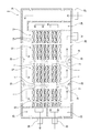
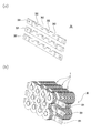
- FIG. 1 is an overall view of a tube heat exchanger according to an embodiment of the present invention, and shows a perspective view.
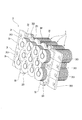
- FIG. It is a principal part schematic diagram of the tube type heat exchanger which concerns on the same embodiment, Comprising: An internal plan view is shown.
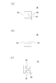
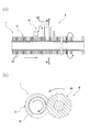
- connection member in the holder concerning the embodiment, (a) is a top view, (b) is a front view, (c) shows a side view. It is a figure explaining the manufacturing method of the heat exchanger tube in the tube type heat exchanger concerning the embodiment, (a) is a longitudinal cross-sectional view, (b) shows the cross-sectional view in the AA line. It is a figure explaining the manufacturing method of the heat exchanger tube in the tube type heat exchanger concerning the embodiment, (a) is a longitudinal cross-sectional view, (b) shows the expanded sectional view in the BB line.
- the tube heat exchanger includes a plurality of heat transfer tubes 1 arranged in parallel so that the axial directions are parallel (substantially parallel), and each heat transfer tube 1. Is provided with a plurality of holders 3 for holding the heat transfer tubes 1.
- the heat exchanger tube 1 is "tube”
- the apparatus main body 2 is “shell”
- heat exchanger itself is a “shell and tube type heat exchanger.” And called each.
- Each heat transfer tube 1 includes a tube body 11 through which a fluid (a heat transfer target body) such as a gas or a liquid passes, and a spiral fin 12 disposed on the outer periphery of the tube body 11.
- a fluid a heat transfer target body
- Each heat transfer tube 1 is fixed to the apparatus main body 2 by connecting both ends of the tube body 11 to the apparatus main body 2.
- Each of the heat transfer tubes 1 is arranged in a plurality of rows in the radial direction (vertical direction or horizontal direction) of the heat transfer tube 1 and is axially centered with another heat transfer tube 1 provided adjacent in the radial direction of the heat transfer tube 1. The distances between them are equal to each other. Moreover, each heat transfer tube 1 is arranged so that the outer edge side (tip side) of its own spiral fin 12 enters the spiral fin 12 of another heat transfer tube 1 that is adjacent in the radial direction of the heat transfer tube 1. That is, the spiral fins 12, 12 adjacent in the radial direction of the heat transfer tube 1 overlap in the axial direction of the heat transfer tube 1.
- Each tube 11 has the same diameter in the axial direction and is formed into a straight tube, that is, a straight tube.
- Each tube 11 is made of a metal having high thermal conductivity such as carbon steel or stainless steel.
- a plurality of spiral fins 12 are juxtaposed in the axial direction of each heat transfer tube 1 such that the ends thereof are separated from each other in the axial direction of the heat transfer tube 1.
- Each spiral fin 12 is configured such that fins (in the present application, a portion around the outer periphery of the tube body 11 is defined as one “fin”) 121 are arranged spirally along the outer periphery of the tube body 11. Yes.
- the spiral fin 12 is made of a metal having high thermal conductivity such as aluminum or copper.
- Each spiral fin 12 is a plate-like body extending in the radial direction of the heat transfer tube 1 (tube body 11), and has a spiral plate shape in which the axial center coincides with the axis of the heat transfer tube 1 (tube body 11). Formed in the body.
- Each spiral fin 12 is configured by connecting the fins 121 so that the fins 121 are equally spaced in the axial direction of the heat transfer tube 1.
- each spiral fin 12 is formed so that the spiral direction of the fins 121 provided in the other adjacent heat transfer tubes 1 and the fin 121 are opposite to each other.
- the spiral fins 12 and 12 adjacently arranged in the radial direction of the heat transfer tube 1 are arranged so that the fins 121 are parallel to each other.
- the apparatus main body 2 includes a body 21 having a sealed space inside, a fluid inlet portion 22 for allowing fluid to flow into the body 21, and a fluid flowing from the fluid inlet portion 22 into each heat transfer tube 1 on the forward path side.
- a third reservoir 25 for joining the fluids flowing out from the heat transfer tubes 1 and a fluid outlet 26 for flowing the fluid of the third reservoir 25 out of the body 21 are provided.
- the apparatus main body 2 includes a medium inlet 27 for flowing a heat medium (heating medium or cooling medium) such as gas or fluid into the body 21, and the inside of the body 21 and the outside of each heat transfer tube 1.
- a medium outlet 28 is provided for allowing the circulated heat medium to flow out of the body 21. 1 and 2, the flow of fluid is indicated by solid arrows, and the flow of the heat medium is indicated by broken arrows.
- the apparatus main body 2 connects one end portion of each heat transfer tube 1 on the forward path side to the side wall of the first storage portion 23, and the other end portion of each heat transfer tube 1 on the forward path side to the side wall of the second storage portion 24. By connecting, each heat transfer tube 1 on the forward path side is fixed. And the apparatus main body 2 connects the one end part of each heat exchanger tube 1 of a return path side to the side wall of the 3rd storage part 25, and uses the other end part of each heat transfer pipe 1 of a return path side to the side wall of the 2nd storage part 24. By connecting, the heat transfer tubes 1 on the return path side are fixed.
- Each holding tool 3 is disposed between the spiral fins 12, 12 and sandwiches each tubular body 11, and is sandwiched between each spiral fin 12, 12 and sandwiches each tubular body 11. And a plurality of connecting members 32 for connecting the members 31, 31 to each other.
- Each holder 3 includes a fixing means 33 for fixing each holding member 31 to the apparatus main body 2.
- each holder 3 is arranged between each spiral fin 12, 12, and holds each heat transfer tube 1 without being in contact with each spiral fin 12 by contacting the outer peripheral portion of each tube 11.
- a plurality of holders 3 are arranged in parallel in the axial direction of the heat transfer tubes 1 and hold a plurality of locations of each heat transfer tube 1.
- Each clamping member 31 is formed in a long plate shape, and includes a plurality of clamping parts 311 that clamp the tube body 11 at the upper edge part and the lower edge part. Each clamping member 31 includes a locking portion 312 that locks the connection member 32 in order to prevent the connection member 32 from being relatively displaced. And each clamping member 31 is equipped with the hole parts 313 and 313 for fixing to the trunk
- the sandwiching member 31 is arranged so that the longitudinal direction is orthogonal to the axial direction of the heat transfer tube 1 (tube body 11), and a plurality of the sandwiching members 31 are arranged in the vertical direction.
- There are two types of the clamping member 31 (FIGS. 5A and 5B) in which the arrangement of the clamping part 311 and the locking part 312 is different, and they are alternately arranged in the vertical direction. Yes.
- the sandwiching portion 311 is formed in a semicircular concave shape at the upper edge of the sandwiching member 31 so as to fit the lower side of the tube body 11, and the sandwiching member 31 so as to fit the upper side of the tube body 11.
- a semicircular concave shape is formed at the lower edge of the.
- locking part 312 is formed in the rectangular concave shape in the upper edge part of the clamping member 31, so that the connection member 32 may be fitted and latched.
- the connecting member 32 is a concave first fitting portion 321 that fits the lower edge portion of the clamping member 31 and a concave shape that fits the upper edge portion of the other clamping member 31 arranged immediately below the clamping member 31.
- the connection member 32 includes a locked portion 323 that is disposed between the fitting portions 321 and 322 and is locked to the locking portion 312 of the holding member 31.
- the configuration of the tube heat exchanger according to the present embodiment is as described above. Next, a method for manufacturing the tube heat exchanger according to the present embodiment will be described.
- the spiral fin 12 of the heat transfer tube 1 is formed by the rolling device 7 as a first step (spiral fin forming step).
- first step raw materials for the rolling device 7 and the heat transfer tube 1 will be explained.
- the rolling device 7 includes a plurality of rolling portions 71 having spiral disk blades 711 and support means (not shown) 72 that supports the heat transfer tube 1.
- the disk blade 711 of each rolled portion 71 rotates around the axial direction of the heat transfer tube 1 and presses the heat transfer tube 1 from the outside in the radial direction of the heat transfer tube 1.
- the support means 72 rotates the heat transfer tube 1 around the axial direction of the heat transfer tube 1 and moves along the axial direction of the heat transfer tube 1 while supporting the heat transfer tube 1.
- the heat transfer tube 1 is manufactured from a raw material in which an inner tube 1a formed of carbon steel, stainless steel, or the like is covered with an outer tube 1b formed of aluminum, copper, or the like.
- each rolling portion 71 rotates while pressing the outer tube 1b from three directions, and the support means 72 rotates the heat transfer tube 1 while moving the heat transfer tube 1 in the axial direction of the heat transfer tube 1.
- the inner tube 1a is pressure-bonded to the outer tube 1b, and the outer tube 1b is pushed out (stretched) in the radial direction of the heat transfer tube 1.
- the outer tube 1 b extruded in the radial direction of the heat transfer tube 1 is processed into the spiral spiral fin 12 by the disk blade 711 formed in a spiral shape.
- the fin 121 (part of the spiral fin 12) of the heat transfer tube 1 is cut by the cutting device 8 as a second step (fin cutting step).
- the cutting device 8 prior to explaining the second step, the cutting device 8 will be explained.
- the cutting device 8 includes a cutting part 81 having a plurality of disk blades 811 and a supporting means (not shown) 82 for supporting the heat transfer tube 1.
- the disk blade 811 of each cutting portion 81 rotates about the axial direction of the heat transfer tube 1 and contacts and separates from the heat transfer tube 1 in the radial direction of the heat transfer tube 1, while the support means 82 is connected to the heat transfer tube 1. Is rotated around the axial direction of the heat transfer tube 1 and is moved along the axial direction of the heat transfer tube 1 while supporting the heat transfer tube 1.
- the disk blade 811 of the cutting unit 81 rotates and approaches the heat transfer tube 1, so that the disk blade 811 cuts to the inner edge (base end) of the predetermined fin 121. Furthermore, when the support means 82 rotates the heat transfer tube 1 and moves the heat transfer tube 1 in the axial direction of the heat transfer tube 1, the disk blade 811 is in a state where the center in the thickness direction coincides with the center in the thickness direction of the fin 121. Then, the fin 121 is cut.
- one spiral fin 12 is divided into a plurality of spiral fins 12 and 12. Therefore, a plurality of spiral fins 12, 12 are arranged in the heat transfer tube 1 in the axial direction of the heat transfer tube 1, and the ends of the spiral fins 12, 12 are separated from each other.
- each heat transfer tube 1 and each holder 3 are assembled as a third step (assembly step). Specifically, as shown in FIGS. 2 and 3, the holder 3 is disposed between the end portions of the spiral fins 12 and 12 that are spaced apart from each other. And each clamping member 31 and each connection member 32 are assembled so that the holder 3 may contact
- the spiral fins 12 are adjacent to each other in the axial direction of the heat transfer tube 1 so that the spiral fins 12 are separated from the heat transfer tube 1.
- each holder 3 can hold
- each heat transfer tube 1 is arranged.
- each heat transfer tube 1 is arranged so that the spiral fins 12, 12 adjacent in the radial direction of the heat transfer tube 1 overlap in the axial direction of the heat transfer tube 1, the apparatus is downsized. be able to.
- each tube heat exchanger since the plurality of clamping members 31 clamp each tube 11, the holder 3 can hold each tube 11 in a stable state.
- each sandwiching portion 311 formed in a concave shape fits a part of each tubular body 11 and sandwiches each tubular body 11, each tubular body 11 is displaced relative to each sandwiching member 31. Can be prevented.
- the connecting member 32 connects the holding members 31 and 31 that hold the pipes 11 together. Therefore, since each clamping member 31 and 31 supports each other by the connection member 32, that is, reinforces each other, each clamping member 31 is prevented from being bent or bent due to its own weight, a load from the heat transfer tube 1, or the like. it can.
- tube heat exchanger and the manufacturing method thereof according to the present invention are not limited to the above-described embodiments, and various modifications can be made without departing from the scope of the present invention. . Moreover, it is needless to say that configurations, methods, and the like according to various modifications described below may be arbitrarily selected and employed in the configurations, methods, and the like according to the above-described embodiments.
- each heat transfer tube is configured such that spiral fins 12, 12 adjacent in the radial direction of the heat transfer tube 1 overlap in the axial direction of the heat transfer tube 1.
- 1 is arrange
- positioned Spiral fins 12 and 12 adjacently provided in the radial direction of the heat exchanger tube 1 do not overlap in the axial center direction of the heat exchanger tube 1, ie,
- the heat transfer tubes 1 may be arranged so as to be separated from each other.
- each heat transfer tube 1 is disposed along the axial direction along the horizontal direction (lateral direction) is not limited to such a case.
- the heat transfer tubes 1 may be arranged along the vertical direction (vertical direction) in the axial direction, or the heat transfer tubes 1 are arranged along the direction in which the axial direction is inclined with respect to the horizontal direction. But you can.
- the holder 30 includes a plurality of support members 301 that support each tube body 11 from below, and each support member 301 prevents each tube body 11 from being relatively displaced.
- the tubular body 11 may be held by providing the upper edge with a recess 302 for fitting the lower side of the tubular body 11.
- connection member 32 when the connection member 32 fits the clamping members 31 and 31 in each fitting part 321,322, the case where the clamping members 31 and 31 are connected mutually.
- the connection member may be a case where the clamping members are coupled to each other by fastening means or the like.
- the heat transfer tube may be formed by forming the tube body and the spiral fin from independent members. Specifically, the super high frequency current is passed through the spiral fin and the tube, and the spiral fin disposed on the outer periphery of the tube is continuously welded (welded) so that it is adjacent to the axial center of the heat transfer tube.
- the plurality of spiral fins may be arranged in parallel in the axial direction of the heat transfer tube so that the spiral fins are separated from each other, and the spiral fins arranged on the outer peripheral portion by expanding the tube It is also possible that a plurality of spiral fins are juxtaposed in the axial direction of the heat transfer tube so that the adjacent spiral fins are separated in the axial direction of the heat transfer tube.
- the heat transfer tube 10 may be formed from a raw material in which the inner tube 10a is covered with the outer tube 10b and the outer tube 10b has a small diameter portion 10c.
- the spiral fin 12 is formed in the large diameter portion 10d by the rolling device 7, while the spiral fin 12 is not formed in the small diameter portion 10c.
- a plurality of spiral fins 12 are juxtaposed in the axial direction of the heat transfer tube 1 such that the adjacent spiral fins 12, 12 are separated from each other in the axial direction of the heat transfer tube 1.
- the cutting part 81 moves the heat exchanger tube 1 in the axial direction of the heat exchanger tube 1 by the support means 82 of the cutting device 8, and the cutting part 81 is the heat exchanger tube 1.
- the present invention is not limited to such a case.
- the cutting unit 81 moves in the axial direction of the heat transfer tube 1 or the cutting unit.
- the cutting part 81 may be relatively displaced in the axial direction of the heat transfer tube 1 relative to the heat transfer tube 1 by moving both 81 and the support means 82 in the axial direction of the heat transfer tube 1.
- the support means 72 of the rolling device 7 and the support means 82 of the cutting device 8 are individually provided has been described.
- the support means 72 of the rolling device 7 and the support means 82 of the cutting device 8 may be a common support means.
Abstract
Description
2 装置本体
3 保持具
7 転造装置
8 切削装置
10 伝熱管
11 管体
12 スパイラルフィン
30 保持具
31 挟持部材
32 接続部材
121 フィン
311 挟持部
Claims (7)
- 軸心方向が平行となるように並設される複数の伝熱管と、伝熱管を保持する保持具とを備え、
各伝熱管は、内部に流体を通す管体と、フィンが管体の外周部に沿って螺旋状に配置されて構成されるスパイラルフィンとを備えるチューブ式熱交換器において、
各伝熱管は、スパイラルフィンの端部同士が離間するようにして、複数のスパイラルフィンを軸心方向で並設し、
保持具は、スパイラルフィン間に配置されると共に、管体の外周部に当接することを特徴とするチューブ式熱交換器。 - 各伝熱管のスパイラルフィンは、伝熱管の径方向で隣設される他の伝熱管のスパイラルフィンに入り込むように配置される請求項1に記載のチューブ式熱交換器。
- 保持具は、各管体を挟持する複数の挟持部材を備える請求項1又は2に記載のチューブ式熱交換器。
- 挟持部材は、各管体を挟持する挟持部を複数備え、
各挟持部は、各管体の一部を嵌め込むべく凹状に形成される請求項3に記載のチューブ式熱交換器。 - 保持具は、各管体を挟持する挟持部材同士を接続する接続部材をさらに備える請求項3に記載のチューブ式熱交換器。
- 軸心方向が平行となるように並設される複数の伝熱管と、伝熱管を保持する保持具とを備え、各伝熱管は、内部に流体を通す管体と、フィンが管体の外周部に沿って螺旋状に配置されて構成されるスパイラルフィンとを備えるチューブ式熱交換器の製造方法において、
各伝熱管が複数のスパイラルフィンを軸心方向で並設すると共にスパイラルフィンの端部同士が離間するように、各伝熱管のフィンを切削する工程と、
保持具が各伝熱管を保持するように、スパイラルフィン間に保持具を配置し、管体の外周部に保持具を当接させる工程とを備えることを特徴とするチューブ式熱交換器の製造方法。 - 各伝熱管のフィンを切削する際に、伝熱管を支持する支持手段が伝熱管を伝熱管の軸心方向を中心に回転させると共に、フィンを切削する切削部と伝熱管とが伝熱管の軸心方向で相対的に変位すべく、切削部及び支持手段の少なくとも何れか一方が伝熱管の軸心方向で移動する請求項6に記載のチューブ式熱交換器の製造方法。
Priority Applications (4)
| Application Number | Priority Date | Filing Date | Title |
|---|---|---|---|
| US13/583,113 US20120325443A1 (en) | 2010-03-11 | 2010-03-11 | Tube Type Heat Exchanger and Manufacturing Method of the Same |
| PCT/JP2010/054098 WO2011111202A1 (ja) | 2010-03-11 | 2010-03-11 | チューブ式熱交換器及びその製造方法 |
| KR1020127020888A KR20130038187A (ko) | 2010-03-11 | 2010-03-11 | 튜브식 열교환기 및 그 제조방법 |
| JP2012504229A JP5608728B2 (ja) | 2010-03-11 | 2010-03-11 | チューブ式熱交換器及びその製造方法 |
Applications Claiming Priority (1)
| Application Number | Priority Date | Filing Date | Title |
|---|---|---|---|
| PCT/JP2010/054098 WO2011111202A1 (ja) | 2010-03-11 | 2010-03-11 | チューブ式熱交換器及びその製造方法 |
Publications (1)
| Publication Number | Publication Date |
|---|---|
| WO2011111202A1 true WO2011111202A1 (ja) | 2011-09-15 |
Family
ID=44563044
Family Applications (1)
| Application Number | Title | Priority Date | Filing Date |
|---|---|---|---|
| PCT/JP2010/054098 WO2011111202A1 (ja) | 2010-03-11 | 2010-03-11 | チューブ式熱交換器及びその製造方法 |
Country Status (4)
| Country | Link |
|---|---|
| US (1) | US20120325443A1 (ja) |
| JP (1) | JP5608728B2 (ja) |
| KR (1) | KR20130038187A (ja) |
| WO (1) | WO2011111202A1 (ja) |
Cited By (2)
| Publication number | Priority date | Publication date | Assignee | Title |
|---|---|---|---|---|
| JP2015166555A (ja) * | 2014-03-03 | 2015-09-24 | トヨタ自動車株式会社 | 熱電発電装置 |
| WO2016047300A1 (ja) * | 2014-09-25 | 2016-03-31 | 日本軽金属株式会社 | 放熱器の製造方法及び放熱器 |
Families Citing this family (4)
| Publication number | Priority date | Publication date | Assignee | Title |
|---|---|---|---|---|
| NL2009451C2 (en) * | 2012-09-12 | 2014-03-18 | Innalox B V | Boiler wall protection block, assembly of such block and a ferrule, and a boiler provided with such assembly. |
| DE102014002829A1 (de) * | 2014-02-27 | 2015-08-27 | Wieland-Werke Ag | Metallisches Wärmeaustauscherrohr |
| US11035615B2 (en) * | 2018-08-23 | 2021-06-15 | Caterpillar Inc. | Support clip for finned tube type heat exchangers |
| AU2021309644A1 (en) * | 2020-07-13 | 2023-03-09 | Ivys Inc. | Hydrogen fueling systems and methods |
Citations (4)
| Publication number | Priority date | Publication date | Assignee | Title |
|---|---|---|---|---|
| JPS535346U (ja) * | 1976-06-30 | 1978-01-18 | ||
| JPS6113107U (ja) * | 1984-06-29 | 1986-01-25 | 三菱重工業株式会社 | 伝熱管の支持装置 |
| JPS6323564U (ja) * | 1986-07-22 | 1988-02-16 | ||
| WO2008093411A1 (ja) * | 2007-01-31 | 2008-08-07 | Shi Mechanical & Equipment Inc. | スパイラルチューブフィン熱交換器 |
Family Cites Families (20)
| Publication number | Priority date | Publication date | Assignee | Title |
|---|---|---|---|---|
| US1748140A (en) * | 1924-05-07 | 1930-02-25 | Schutte & Koerting Co | Means for supporting and holding pipes in spaced relation to each other |
| US1704097A (en) * | 1924-05-07 | 1929-03-05 | Schutte & Koerting Co | Pipe-supporting means |
| US1617751A (en) * | 1925-06-08 | 1927-02-15 | Fedders Mfg Co Inc | Core for radiators |
| US2021117A (en) * | 1931-03-21 | 1935-11-12 | Babcock & Wilcox Co | Heat exchanger |
| US1907867A (en) * | 1931-12-22 | 1933-05-09 | Westinghouse Electric & Mfg Co | Heat exchanger |
| GB410762A (en) * | 1932-11-22 | 1934-05-22 | Owen David Lucas | Improvements in or relating to apparatus for vaporizing or distilling liquids |
| US3422884A (en) * | 1966-12-28 | 1969-01-21 | Baldwin Lima Hamilton Corp | Condenser tube bundles |
| IT960259B (it) * | 1972-04-20 | 1973-11-20 | Roma C | Pascio tubiero per scambiatori di calore ed elementi modulari per detto costituiti da tubi termopla stici e procedimento di costruzio ne degli elementi modulari e dei fasci tubieri |
| SE415607B (sv) * | 1975-11-04 | 1980-10-13 | Stal Laval Apparat Ab | Anordning for stagning av kamflensror i vermevexlare |
| FR2362358A1 (fr) * | 1976-08-18 | 1978-03-17 | Hamon Sobelco Sa | Echangeur de chaleur a paroi d'echange formee par des tubes souples |
| US4184862A (en) * | 1976-09-30 | 1980-01-22 | Mcdonnell Douglas Corporation | Heat exchanger gas separator |
| US4306697A (en) * | 1980-06-16 | 1981-12-22 | Mathews Lyle H | Conduit spacer system |
| US4769876A (en) * | 1987-02-26 | 1988-09-13 | Platt Richard B | Wire separator structure and method |
| DE3928320A1 (de) * | 1989-08-26 | 1991-03-14 | Drilltec Patents & Tech | Vorrichtung zur lagerung und zum transport von rohren |
| US5181560A (en) * | 1990-10-17 | 1993-01-26 | Burn Mark N | Baffleless tube and shell heat exchanger having fluted tubes |
| US5136985A (en) * | 1991-09-12 | 1992-08-11 | Deltak Corporation | Boiler tube support |
| US5404941A (en) * | 1993-08-10 | 1995-04-11 | The Babcock & Wilcox Company | Split ring tube spacer assembly |
| US6007029A (en) * | 1998-06-03 | 1999-12-28 | Astech, Inc. | Boiler tube alignment link system |
| US6592309B1 (en) * | 2001-09-24 | 2003-07-15 | Hp Products Co. | Packaging clip and package |
| DE102008046690A1 (de) * | 2007-09-11 | 2009-03-12 | Behr Gmbh & Co. Kg | Wärmetauscher, insbesondere für ein Kraftfahrzeug |
-
2010
- 2010-03-11 US US13/583,113 patent/US20120325443A1/en not_active Abandoned
- 2010-03-11 JP JP2012504229A patent/JP5608728B2/ja active Active
- 2010-03-11 WO PCT/JP2010/054098 patent/WO2011111202A1/ja active Application Filing
- 2010-03-11 KR KR1020127020888A patent/KR20130038187A/ko not_active Application Discontinuation
Patent Citations (4)
| Publication number | Priority date | Publication date | Assignee | Title |
|---|---|---|---|---|
| JPS535346U (ja) * | 1976-06-30 | 1978-01-18 | ||
| JPS6113107U (ja) * | 1984-06-29 | 1986-01-25 | 三菱重工業株式会社 | 伝熱管の支持装置 |
| JPS6323564U (ja) * | 1986-07-22 | 1988-02-16 | ||
| WO2008093411A1 (ja) * | 2007-01-31 | 2008-08-07 | Shi Mechanical & Equipment Inc. | スパイラルチューブフィン熱交換器 |
Cited By (4)
| Publication number | Priority date | Publication date | Assignee | Title |
|---|---|---|---|---|
| JP2015166555A (ja) * | 2014-03-03 | 2015-09-24 | トヨタ自動車株式会社 | 熱電発電装置 |
| WO2016047300A1 (ja) * | 2014-09-25 | 2016-03-31 | 日本軽金属株式会社 | 放熱器の製造方法及び放熱器 |
| JP2016064484A (ja) * | 2014-09-25 | 2016-04-28 | 日本軽金属株式会社 | 放熱器の製造方法及び放熱器 |
| TWI726848B (zh) * | 2014-09-25 | 2021-05-11 | 日商日本輕金屬股份有限公司 | 散熱器 |
Also Published As
| Publication number | Publication date |
|---|---|
| KR20130038187A (ko) | 2013-04-17 |
| US20120325443A1 (en) | 2012-12-27 |
| JPWO2011111202A1 (ja) | 2013-06-27 |
| JP5608728B2 (ja) | 2014-10-15 |
Similar Documents
| Publication | Publication Date | Title |
|---|---|---|
| JP5608728B2 (ja) | チューブ式熱交換器及びその製造方法 | |
| US20120199331A1 (en) | Shell-and-tube heat exchangers with foam heat transfer units | |
| US11359838B2 (en) | Heat exchanger and manufacturing method therefor | |
| JP5638672B2 (ja) | 超高純度インライン熱交換器 | |
| GB2591972A (en) | Ribbed tubeless heat exchanger for fluid heating systems including a rib component and methods of manufacture thereof | |
| US20180245817A1 (en) | Heat exchanger and production method of the heat exchanger | |
| JP2018529922A (ja) | 熱交換器のための熱交換管、熱交換器、およびその組立方法 | |
| KR101727276B1 (ko) | 열교환기용 튜브시트 제조방법 | |
| JP2018179493A (ja) | 熱交換器用マニホールド、熱交換器、およびその製造方法 | |
| US20150144309A1 (en) | Flattened Envelope Heat Exchanger | |
| CN110567298A (zh) | 一种嵌套式螺旋折流板及换热器 | |
| EP2735835A2 (en) | Internal heat exchanger for an air conditioning system | |
| JPH03238128A (ja) | 熱交換器及びその製造方法 | |
| JP6150380B2 (ja) | 熱交換器及び熱交換器の製造方法 | |
| KR20130001224A (ko) | 열 교환기 핀, 조립체 및 방법 | |
| JP2017090412A (ja) | 冷却管ユニットの製造方法、管内整流具、冷却管、及び、管内整流具の固定構造 | |
| WO2015081274A1 (en) | Flattened envelope heat exchanger | |
| WO2018158843A1 (ja) | 熱交換器 | |
| JPH03251686A (ja) | 熱交換器 | |
| US11209219B1 (en) | Circumferential flow foam heat exchanger | |
| WO2012081379A1 (ja) | 熱交換器における邪魔板の製造方法、および、熱交換器の製造方法 | |
| JP2005214471A (ja) | プレート式熱交換器とその製造方法 | |
| CN111133269B (zh) | 管连接 | |
| RU2719776C2 (ru) | Способ изготовления пластинчатого щелевого теплообменника | |
| KR20230139445A (ko) | 열교환기 |
Legal Events
| Date | Code | Title | Description |
|---|---|---|---|
| 121 | Ep: the epo has been informed by wipo that ep was designated in this application |
Ref document number: 10847432 Country of ref document: EP Kind code of ref document: A1 |
|
| WWE | Wipo information: entry into national phase |
Ref document number: 2012504229 Country of ref document: JP |
|
| ENP | Entry into the national phase |
Ref document number: 20127020888 Country of ref document: KR Kind code of ref document: A |
|
| WWE | Wipo information: entry into national phase |
Ref document number: 13583113 Country of ref document: US |
|
| NENP | Non-entry into the national phase |
Ref country code: DE |
|
| 122 | Ep: pct application non-entry in european phase |
Ref document number: 10847432 Country of ref document: EP Kind code of ref document: A1 |