WO2011111177A1 - 擬似音発生装置及び擬似音発生方法 - Google Patents
擬似音発生装置及び擬似音発生方法 Download PDFInfo
- Publication number
- WO2011111177A1 WO2011111177A1 PCT/JP2010/053960 JP2010053960W WO2011111177A1 WO 2011111177 A1 WO2011111177 A1 WO 2011111177A1 JP 2010053960 W JP2010053960 W JP 2010053960W WO 2011111177 A1 WO2011111177 A1 WO 2011111177A1
- Authority
- WO
- WIPO (PCT)
- Prior art keywords
- sound
- pseudo
- vehicle
- bumper
- generated
- Prior art date
- Legal status (The legal status is an assumption and is not a legal conclusion. Google has not performed a legal analysis and makes no representation as to the accuracy of the status listed.)
- Ceased
Links
Images



Classifications
-
- B—PERFORMING OPERATIONS; TRANSPORTING
- B60—VEHICLES IN GENERAL
- B60Q—ARRANGEMENT OF SIGNALLING OR LIGHTING DEVICES, THE MOUNTING OR SUPPORTING THEREOF OR CIRCUITS THEREFOR, FOR VEHICLES IN GENERAL
- B60Q5/00—Arrangement or adaptation of acoustic signal devices
- B60Q5/005—Arrangement or adaptation of acoustic signal devices automatically actuated
- B60Q5/008—Arrangement or adaptation of acoustic signal devices automatically actuated for signaling silent vehicles, e.g. for warning that a hybrid or electric vehicle is approaching
-
- G—PHYSICS
- G10—MUSICAL INSTRUMENTS; ACOUSTICS
- G10K—SOUND-PRODUCING DEVICES; METHODS OR DEVICES FOR PROTECTING AGAINST, OR FOR DAMPING, NOISE OR OTHER ACOUSTIC WAVES IN GENERAL; ACOUSTICS NOT OTHERWISE PROVIDED FOR
- G10K15/00—Acoustics not otherwise provided for
- G10K15/02—Synthesis of acoustic waves
Definitions
- the present invention relates to a pseudo sound generating device and a pseudo sound generating method.
- Patent Document 1 hereinafter referred to as “Conventional Example 1”.
- a pseudo sound signal is generated on the basis of detection results such as the vehicle speed, the rotational speed of the motor that is the power source, the accelerator opening degree, and the like, and the pseudo sound is output from the speaker to the front outside the vehicle. It has become.
- the execution / non-execution of the pseudo sound output is controlled according to the type of region in which the vehicle is traveling.
- a technique for utilizing the outer wall of the vehicle as a sounding body has been proposed as a technique for transmitting acoustic information in the vehicle interior to the outside of the vehicle (see Patent Document 2).
- a vibration actuator fixed to the outer plate surface inside a hollow outer wall member such as a door of a vehicle is driven.
- the outer plate is vibrated locally by vibrating the vibration actuator.
- the outer plate serves as a sounding body, and acoustic information in the vehicle interior is transmitted to the outside of the vehicle.
- the technique of Conventional Example 1 requires a large dynamic speaker such as a high-power amplifier that is heavy in weight. For this reason, power consumption becomes large, and the fuel consumption of the vehicle may be reduced.
- the present invention has been made in view of the above circumstances, and an object of the present invention is to provide a new pseudo-sound generator and a pseudo-sound generation method that can appropriately output a pseudo sound corresponding to a running state of a vehicle to the outside of the vehicle. .
- the present invention is a pseudo-sound generator mounted on a vehicle having a bumper, an acquisition unit that acquires travel information including a vehicle speed of the vehicle; and based on the acquired travel information
- a generating unit that generates a pseudo sound signal
- a vibration actuator that is installed on a surface of the bumper on the vehicle body side and vibrates the bumper according to the generated pseudo sound signal. This is a pseudo sound generator.
- the present invention is a pseudo sound provided with a vibration actuator that is mounted on a vehicle body side surface of the bumper and that vibrates the bumper according to a received pseudo sound signal.
- a pseudo-sound generation method used in a generator an acquisition step of acquiring travel information including a vehicle speed of the vehicle; a generation step of generating a pseudo-sound signal based on the acquired travel information; And a pseudo sound output step of vibrating the bumper by vibrating the vibration actuator in accordance with the pseudo sound signal.
- FIG. 1 is a block diagram illustrating a schematic configuration of a pseudo engine sound generation apparatus 100 as a pseudo sound generation apparatus according to an embodiment.
- the pseudo engine sound generating device 100 is mounted on a vehicle CR equipped with a front bumper BNF and a rear bumper BNR.
- the vehicle CR is equipped with an accelerator information sensor 910 that detects accelerator information corresponding to the accelerator opening, and a rotation speed information sensor 920 that detects rotation speed information corresponding to the engine speed.
- the forward direction of the vehicle CR is also referred to as the X direction, the width direction as the Y direction, and the upward direction as the Z direction.
- the pseudo engine sound generator 100 includes an acquisition unit 110 and a digital processing unit 120.
- the pseudo engine sound generation apparatus 100 includes an analog processing unit 130 and a sound output unit 140.
- the acquisition unit 110 receives the measurement signal AAS sent from the accelerator information sensor 910 equipped in the vehicle CR and the measurement signal ERS sent from the rotation speed information sensor 920. Then, the acquiring unit 110 converts the measurement signal AAS into accelerator information AR having a signal form that can be processed by the digital processing unit 120. The accelerator information AR obtained in this way is sent to the digital processing unit 120.
- the acquisition unit 110 converts the measurement signal ERS into rotation speed information ER having a form that can be processed by the digital processing unit 120.
- the rotation speed information ER obtained in this way is sent to the digital processing unit 120.
- an accelerator information sensor 910 such as an accelerator opening sensor and an engine speed information sensor 920 such as an engine speed mounted on the vehicle CR, and an ECU (Electrical Control Unit) that controls the traveling of the vehicle CR
- the measurement signals AAS and ERS are obtained by biting the detection harness into the signal harness for connecting the output harness or connecting the output harness drawn from the ECU for the add-on vehicle-mounted device to the pseudo engine sound generation device 100. 110 is supplied.
- the digital processing unit 120 receives the accelerator information AR and the rotation speed information ER sent from the acquisition unit 110. Then, the digital processing unit 120 generates the high-frequency component data PED H and the low-frequency component data PED L of the pseudo engine sound based on the accelerator information AR and the rotation speed information ER. The high tone component data PED H and the low tone component data PED L generated in this way are sent to the analog processing unit 130. Details of the configuration of the digital processing unit 120 will be described later.
- the analog processing unit 130 receives the high tone component data PED H and the low tone component data PED L sent from the digital processing unit 120.
- the analog processing unit 130 is provided with a set of a DA (Digital to Analogue) converter and a power amplifier corresponding to each of the high sound component data PED H and the low sound component data PED L.
- DA Digital to Analogue
- the sound output unit 140 receives the high tone component output signal AOS H and the low tone component output signal AOS L sent from the analog processing unit 130. Then, the sound output unit 140 generates a pseudo engine sound according to the high sound component output signal AOS H and the low sound component output signal AOS L sent from the analog processing unit 130, and outputs them to the outside of the vehicle. Details of the configuration of the digital processing unit 120 will be described later.
- the digital processing unit 120 includes a storage unit 121 and a generation unit 122.
- the digital processing unit 120 includes a high pass filter (HPF) 123 and a low pass filter (LPF) 124.
- HPF high pass filter
- LPF low pass filter
- the storage unit 121 stores various information data used by the digital processing unit 120.
- the information data stored in the storage unit 121 in this way includes a waveform table WFT.
- the waveform pattern of the pseudo engine sound is registered in association with the combination of the rotational speed information corresponding to the engine rotational speed and the accelerator information corresponding to the accelerator opening angle.
- the waveform pattern is registered in association with each combination of the range of the rotation speed information ER and the range of the accelerator information AR.
- the relationship between the combination of the range of the rotational speed information ER and the range of the accelerator information AR and the waveform pattern is the vehicle type of the vehicle CR obtained in advance based on experiments, experiences, etc., depending on the type of the vehicle CR. Average relationship.
- the generation unit 122 receives the accelerator information AR and the rotation speed information ER sent from the acquisition unit 110. Subsequently, the generation unit 122 reads the waveform pattern data WFD registered in the waveform table WFT in association with the combination of the accelerator information AR and the rotation speed information ER. Then, the generation unit 122 generates pseudo engine sound data PED that is a digital signal based on the read data WFD. The pseudo engine sound data PED generated in this way is sent to the HPF 123 and the LPF 124.
- the HPF 123 receives the pseudo engine sound data PED sent from the generation unit 122. Then, the HPF 123 passes a frequency component higher than the predetermined frequency FC in the pseudo engine sound data PED, and sends it to the analog processing unit 130 as the high sound component data PED H.
- the LPF 124 receives the pseudo engine sound data PED sent from the generation unit 122. Then, the LPF 124 passes a frequency component lower than the predetermined frequency FC in the pseudo engine sound data PED, and sends the low frequency component data PED L to the analog processing unit 130.
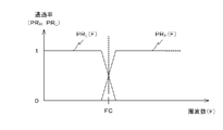
- FIG. 4 An example of the pass characteristics of the HPF 123 and the LPF 124 is shown in FIG. In FIG. 4, the pass characteristic of the HPF 123 is shown as PR H (F), and the pass characteristic of the LPF 124 is shown as PR L (F).
- the “predetermined frequency FC” is determined in advance based on experiments, simulations, experiences, and the like, corresponding to the generation characteristics of the high-frequency component output signal AOS H and the low-frequency component output signal AOS L in the sound output unit 140.
- the sound output unit 140 includes sound generation units 141 1 and 141 2 , a sound waveguide member 142, and a sound insulation member 143.
- the vibration actuator 145 j receives the bass component output signal AOS L sent from the analog processing unit 130. Then, the vibration actuator 145 j generates a low-frequency component in the pseudo engine sound by vibrating the front bumper BNF to which the vibration actuator 145 j is fixed as described later according to the low-frequency component output signal AOS L.
- the speaker 146 j receives the treble component output signal AOS H sent from the analog processing unit 130. Then, the speaker 146 j generates a high sound component in the pseudo engine sound according to the high sound component output signal AOS H.
- the sound generating unit 141 j as shown in FIG. 6 (B), in addition to the vibration actuator 145 j and a speaker 146 j, and a fixing member 149 for fixing the speaker 146 j.
- the vibration actuator 145 j includes a vibration plate 147 and a vibrator 148 fixed to the vibration plate 147.
- the surface of the diaphragm 147 opposite to the surface on which the vibrator 148 is fixed is the surface of the front bumper BNF on the ⁇ X direction side (that is, the vehicle body side) via the adhesive member 150 made of a thermosetting resin. It is fixed to. As a result, when the vibration actuator 145 j vibrates, the front bumper BNF vibrates.
- the diaphragm 147 and the fixing member 149 form an internal space opened in the ⁇ X direction.
- the speaker 146 j is accommodated in this internal space so as to face the ⁇ X direction side. As a result, the speaker 146 j outputs sound toward the ⁇ X direction side.
- the sound waveguide member 142 is formed with an opening 142O j for capturing the sound output from the speaker 146 j at a position facing the sound generator 141 j .
- the sound waveguide member 142 guides the sound taken in from the opening 142O j in the Y-axis direction and outputs it from the openings at both ends in the Y-axis direction.
- the sound waveguide member 142 is fixed to the vehicle body by a fixing member (not shown).
- the sound insulating member 143 is a flexible member having a sound absorbing property and is on the ⁇ X direction side of the sound waveguide member 142 and between the sound waveguide member 142 and the vehicle interior. Be placed. The sound insulation member 143 prevents propagation of sound output from the speaker 146 j that has not been taken into the sound waveguide member 142 to the passenger compartment.
- the acquisition unit 110 receives the measurement signal AAS sent from the accelerator information sensor 910 and the measurement signal ERS sent from the rotation speed information sensor 920. Subsequently, the acquisition unit 110 converts the measurement signal AAS into accelerator information AR having a signal form that can be processed by the digital processing unit 120, and the rotation speed information ER having a form that can be processed by the digital processing unit 120. Convert to Then, the acquisition unit 110 sends the accelerator information AR and the rotation speed information ER to the digital processing unit 120 (see FIG. 1).
- the generation unit 122 receives the accelerator information AR and the rotation speed information ER.
- the generation unit 122 reads the waveform pattern data WFD registered in the waveform table WFT in the storage unit 121 in association with the combination of the accelerator information AR and the rotation speed information ER.
- the generation unit 122 determines whether or not the waveform pattern should be changed by determining whether or not the newly read waveform pattern has changed from the current waveform pattern.
- the generation unit 122 continues to generate the pseudo engine sound data PED corresponding to the waveform pattern currently employed. Then, the generation unit 122 sends the generated pseudo engine sound data PED to the HPF 123 and the LPF 124 (see FIG. 2).
- the generation unit 122 starts generating the pseudo engine sound signal PED based on the newly read waveform pattern. Then, the generation unit 122 sends the generated pseudo engine sound data PED to the HPF 123 and the LPF 124 (see FIG. 2).
- the HPF 123 passes a frequency component higher than the predetermined frequency FC in the pseudo engine sound data PED, and sends it to the analog processing unit 130 as the high sound component data PED H. Further, the LPF 124 passes the frequency component lower than the predetermined frequency FC in the pseudo engine sound data PED, and sends it to the analog processing unit 130 as the low sound component data PED L (see FIG. 2).
- the treble component data PED H is DA-converted and then power amplified to generate the treble component output signal AOS H.
- the bass component data PED L is DA-converted and then power-amplified to generate a bass component output signal AOS L. Then, the analog processing unit 130 sends the generated high tone component output signal AOS H and low tone component output signal AOS L to the sound output unit 140 (see FIG. 1).
- Speaker 146 j which received the treble component output signal AOS H is the treble components of the pseudo engine sound in accordance with treble component output signal AOS H, and outputs toward the -X direction side (vehicle body side).
- treble component output signal AOS H most of the sound output from the speaker 146 j is taken into the sound waveguide member 142 from the opening 142O j .
- the sound taken in this way is guided in the internal space of the sound waveguide member 142 along the Y-axis direction (the width direction of the vehicle CR), and then opened at both ends of the sound waveguide member 142 in the Y-axis direction. Is output to the outside of the vehicle.
- most of the treble component of the pseudo engine sound is output outside the vehicle without being trapped inside the vehicle.
- a portion of the sound output from the speaker 146 j that has not been taken into the sound waveguide member 142 proceeds toward the passenger compartment, but the progress is blocked by the sound insulating member 143. As a result, the amount of the high-frequency component of the pseudo engine sound that reaches the passenger compartment is reduced.
- Vibration actuator 145 j which receives the bass component output signal AOS L oscillates according bass component output signal AOS L.
- the front bumper BNF to which the vibration actuator 145 j is fixed vibrates, and a low-frequency component of the pseudo engine sound that goes to the outside of the vehicle is generated.
- parts of the vehicle that are directly or indirectly coupled to the front bumper BNF vibrate, and a bass component of the pseudo engine sound is also generated in those parts.
- the generating unit 122 generates the pseudo engine sound data PED based on the vehicle travel information acquired by the acquiring unit 110. Subsequently, after the pseudo engine sound data PED is separated into the high sound component data PED H and the low sound component data PED L by the HPF 123 and the LPF 124, the high sound component output signal AOS H and the low sound component output are output via the analog processing unit 130. Signal AOS L is generated.
- the vibration actuator 145 j vibrates the front bumper BNF, and a bass component of the pseudo engine sound that goes to the outside of the vehicle is generated.
- the low-frequency component of the pseudo engine sound can be generated at a position close to the engine in the gasoline vehicle, and the low-frequency component of the pseudo engine sound can be efficiently output outside the vehicle without being trapped inside the vehicle. .
- the low frequency component of the pseudo engine sound can be output to the outside in the same manner as the engine sound accompanying the operation of the engine in the gasoline vehicle.
- the pseudo engine sound corresponding to the traveling state of the vehicle CR can be appropriately output to the outside of the vehicle.
- the speaker 146 j disposed in the vicinity of the front bumper BNF outputs a high-frequency component of the pseudo engine sound toward the rear of the vehicle.
- the sound waveguide member 142 causes the inside of the sound waveguide member 142 to pass through the inside space.
- the light is guided along the width direction of the vehicle CR, and output from the side of the vehicle CR toward the outside of the vehicle.
- the sound insulation member 143 is disposed between the generation source of the pseudo engine sound and the passenger compartment. For this reason, most of the pseudo engine sound toward the passenger compartment can be blocked, and the intrusion of the pseudo engine noise into the passenger compartment can be prevented.
- each of the sound generators 141 j 1, 2) includes the vibration actuator 145 j and the speaker 146 j .
- the speaker 146 j may not be included.
- the vibration actuator 145 j receives the bass and treble output signals sent from the analog processing unit 130 and vibrates the front bumper BNF according to these signals.
- the sound waveguide member 142 takes in the sound wave generated by the vibration of the front bumper BNF through the opening 142O j and outputs it from the openings at both ends in the Y-axis direction.
- thermosetting resin is used as the adhesive member 150.
- a photocurable resin or a thermoplastic resin can also be used.
- the number of the sound generating units 141 is two, but may be one, or may be three or more.
- the sound output to the outside of the vehicle is a pseudo engine sound.
- pseudo sounds may be used, or other types of pseudo sounds may be superimposed on the pseudo engine sounds.
- the sound waveguide member 142 is prepared separately from the vehicle part.
- the opening 142O is formed in the lean force.
- j may be formed and used as the sound waveguide member 142.
- the pseudo engine sound signal is separated into the high sound component output signal AOS H and the low sound component output signal AOS L.
- the accelerator information and the rotational speed information are adopted as the traveling information of the vehicle CR to be referred to when generating the pseudo engine sound data, but instead of these information or in addition to these information.
- Vehicle speed information, acceleration information, ignition switch information, etc. may be referred to.
Landscapes
- Physics & Mathematics (AREA)
- Engineering & Computer Science (AREA)
- Acoustics & Sound (AREA)
- Health & Medical Sciences (AREA)
- Audiology, Speech & Language Pathology (AREA)
- General Health & Medical Sciences (AREA)
- Multimedia (AREA)
- Mechanical Engineering (AREA)
- Electric Propulsion And Braking For Vehicles (AREA)
- Fittings On The Vehicle Exterior For Carrying Loads, And Devices For Holding Or Mounting Articles (AREA)
Abstract
取得部により取得された車両の走行情報に基づいて、擬似音エンジン音データとして高音成分出力信号AOSH及び低音成分出力信号AOSLが生成される。そして、低音成分出力信号AOSLに従って、振動アクチュエータ145j(j=1,2)がバンパーを振動させることにより、車外へ向かう擬似エンジン音の低音成分を発生させる。また、バンパーを振動させること、バンパーと直接又は間接的に結合された車両の部分を振動させ、それらの部分においても擬似エンジン音の低音成分を発生させる。この結果、ガソリン車におけるエンジンに近い位置で擬似エンジン音の低音成分を発生させることができるとともに、車両内にこもらせることなく、効率的に擬似エンジン音の低音成分を車外へ出力することができる。
Description
本発明は、擬似音発生装置及び擬似音発生方法に関する。
近年、電池を駆動力源とする電気自動車や、電池を駆動力源の一部とするハイブリッド車の普及が進んでいる。こうした自動車が、電池を駆動力源として走行する場合には、従来のガソリン車と比べて、車外における駆動音のレベルが飛躍的に低くなる。この結果、歩行者や自転車の運転者が、後方等の視野外から接近する車両の存在に気付けない事態が起こり得る。かかる事態の発生は、交通安全上、深刻な問題である。
このため、車両の走行状況に対応する擬似エンジン音を車外へ出力する技術が提案されている(特許文献1:以下、「従来例1」と呼ぶ)。この従来例1の技術では、車速、動力源であるモータの回転数、アクセル開度等の検出結果に基づいて、擬似音信号を生成してスピーカから車外前方等へ擬似音を出力するようになっている。なお、従来例1の技術では、車両が走行している地域の種類に応じて、擬似音出力の実行/非実行を制御するようになっている。
また、擬似エンジン音を車外へ出力する技術ではないが、車室内の音響情報を車外へ伝達する技術として、車両の外壁を発音体として利用する技術も提案されている(特許文献2参照)。この従来例2の技術では、車両のドア等の中空の外壁部材内部における外板表面に固定された振動アクチュエータを駆動するようになっている。そして、振動アクチュエータを振動させることにより、外板を局所的に振動させる。この結果、外板が発音体となって、車室内の音響情報が車外に伝達されるようになっている。
上述した従来例1の技術では、スピーカを利用して擬似エンジン音を車外に出力する。しかしながら、スピーカには音出力方向に指向性があり、スピーカが向いている方向の垂直方向や反対方向への音の広がりは期待できない。このため、周囲の歩行者等に対して警告をする目的で擬似エンジン音を出力しても、十分な効果を発揮できるとはいえず、かかる欠点を補うためには、多くのスピーカを用意することが必要であった。
また、擬似エンジン音の出力に際しては、ガソリン車の場合におけるエンジンの近くから出力することが望ましい。しかしながら、従来例1の技術において、いわゆるエンジンルーム内にスピーカを配置すると、当該エンジンルーム内に音がこもってしまう。
さらに、十分な音量の擬似エンジン音を出力できるようにしようとすると、従来例1の技術では、重量が大きく、高出力のパワー増幅器などの必要なダイナミック型のスピーカが必要となる。このため、消費電力が大きくなってしまうとともに、車両の燃費の低下を招くことにもなりかねない。
上述した従来例2は、車室内の音響情報を車外へ伝達する技術なので、そのままでは、擬似エンジン音の車外への出力には適用できない。また、従来例2の技術では、内板と外板とを有する中空の外壁部材内部に振動アクチュエータを配置するので、振動アクチュエータの設置を有意に行えるとはいいがたい。
このため、簡易な、かつ、簡易に設置可能な構成で、車両の走行状態に対応した擬似音を車外へ出力することができる技術が望まれている。かかる要請に応えることが、本発明が解決すべき課題の一つとして挙げられる。
本発明は、上記の事情を鑑みてなされたものであり、車両の走行状態に対応した擬似音を適切に車外へ出力することができる新たな擬似音発生装置及び擬似音発生方法を目的とする。
本発明は、第1の観点からすると、バンパーを有する車両に搭載される擬似音発生装置であって、前記車両の車速を含む走行情報を取得する取得部と;前記取得された走行情報に基づいて、擬似音信号を生成する生成部と;前記バンパーの前記車両の本体側表面上に設置され、前記生成された擬似音信号に従って前記バンパーを振動させる振動アクチュエータと;を備えることを特徴とする擬似音発生装置である。
本発明は、第2の観点からすると、バンパーを有する車両に搭載され、前記バンパーの前記車両の本体側表面上に設置され、受信した擬似音信号に従って前記バンパーを振動させる振動アクチュエータを備える擬似音発生装置において使用される擬似音発生方法であって、前記車両の車速を含む走行情報を取得する取得工程と;前記取得された走行情報に基づいて擬似音信号を生成する生成工程と;前記生成された擬似音信号に従って前記振動アクチュエータを振動させることにより、前記バンパーを振動させる擬似音出力工程と;を備えることを特徴とする擬似音発生方法である。
以下、本発明の一実施形態を、図1~図7を参照して説明する。なお、以下の説明及び図面においては、同一又は同等の要素には同一符号を付し、重複する説明を省略する。
<構成>
図1には、一実施形態に係る擬似音発生装置としての擬似エンジン音発生装置100の概略的な構成が、ブロック図にて示されている。この図1に示されるように、擬似エンジン音発生装置100は、フロントバンパーBNF及びリアバンパーBNRを装着している車両CRに搭載されている。この車両CRには、アクセル開度に相当するアクセル情報を検出するアクセル情報センサ910、及び、エンジン回転数に相当する回転数情報を検出する回転数情報センサ920を装備している。
<構成>
図1には、一実施形態に係る擬似音発生装置としての擬似エンジン音発生装置100の概略的な構成が、ブロック図にて示されている。この図1に示されるように、擬似エンジン音発生装置100は、フロントバンパーBNF及びリアバンパーBNRを装着している車両CRに搭載されている。この車両CRには、アクセル開度に相当するアクセル情報を検出するアクセル情報センサ910、及び、エンジン回転数に相当する回転数情報を検出する回転数情報センサ920を装備している。
なお、以下に説明においては、車両CRの前方方向をX方向、幅方向をY方向、上方向をZ方向とも呼ぶものとする。
擬似エンジン音発生装置100は、取得部110と、デジタル処理部120とを備えている。また、擬似エンジン音発生装置100は、アナログ処理部130と、音出力部140とを備えている。
上記の取得部110は、車両CRに装備されたアクセル情報センサ910から送られた測定信号AASと、回転数情報センサ920から送られた測定信号ERSとを受ける。そして、取得部110は、測定信号AASをデジタル処理部120で処理可能な信号形態を有するアクセル情報ARに変換する。こうして得られたアクセル情報ARは、デジタル処理部120へ送られる。
また、取得部110は、測定信号ERSをデジタル処理部120で処理可能な形態を有する回転数情報ERに変換する。こうして得られた回転数情報ERは、デジタル処理部120へ送られる。
なお、本実施形態では、車両CRに装備されたアクセル開度センサ等のアクセル情報センサ910及びエンジン回転数等の回転数情報センサ920と、車両CRの走行を制御するECU(Electrical Control Unit)とを接続する信号ハーネスに検出ハーネスを噛ませることにより、又は、ECUからアドオン車載装置向けに引き出されている出力ハーネスを擬似エンジン音発生装置100に接続することにより、測定信号AAS,ERSが取得部110に供給されるようにしている。
上記のデジタル処理部120は、取得部110から送られたアクセル情報AR及び回転数情報ERを受ける。そして、デジタル処理部120は、アクセル情報AR及び回転数情報ERに基づいて、擬似エンジン音の高音成分データPEDH及び低音成分データPEDLを生成する。こうして生成された高音成分データPEDH及び低音成分データPEDLは、アナログ処理部130へ送られる。なお、デジタル処理部120の構成の詳細については、後述する。
上記のアナログ処理部130は、デジタル処理部120から送られた高音成分データPEDH及び低音成分データPEDLを受ける。このアナログ処理部130には、高音成分データPEDH及び低音成分データPEDLのそれぞれに対応して、DA(Digital to Analogue)変換器及びパワー増幅器の組が用意されている。
アナログ処理部130では、高音成分データPEDHをDA変換した後にパワー増幅して、高音成分出力信号AOSHを生成する。また、アナログ処理部130では、低音成分データPEDLをDA変換した後にパワー増幅して、低音成分出力信号AOSLを生成する。こうして生成された高音成分出力信号AOSH及び低音成分出力信号AOSLは、音出力部140へ送られる。
上記の音出力部140は、アナログ処理部130から送られた高音成分出力信号AOSH及び低音成分出力信号AOSLを受ける。そして、音出力部140は、アナログ処理部130から送られた高音成分出力信号AOSH及び低音成分出力信号AOSLに従って擬似エンジン音を発生し、車外へ向けて出力する。なお、デジタル処理部120の構成の詳細については、後述する。
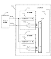
次に、上記のデジタル処理部120の構成について説明する。デジタル処理部120は、図2に示されるように、記憶部121と、生成部122とを備えている。また、デジタル処理部120は、ハイパスフィルタ(HPF)123と、ローパスフィルタ(LPF)124とを備えている。
上記の記憶部121には、デジタル処理部120が利用する様々な情報データが記憶される。こうして記憶部121に記憶される情報データには、波形テーブルWFTが含まれている。
かかる波形テーブルWFTには、エンジン回転数に相当する回転数情報と、アクセル開角に相当するアクセル情報との組み合わせに関連付けて、擬似エンジン音の波形パターンが登録されている。本実施形態では、図3に示されるように、回転数情報ERの範囲とアクセル情報ARの範囲との組み合わせごとに関連付けて、波形パターンが登録されるようになっている。かかる回転数情報ERの範囲とアクセル情報ARの範囲との組み合わせと、波形パターンとの関係は、車両CRの種類に応じて、実験、経験等に基づいて予め得られた、車両CRの車種について平均的な関係となっている。
上記の生成部122は、取得部110から送られたアクセル情報AR及び回転数情報ERを受ける。引き続き、生成部122は、当該アクセル情報ARと当該回転数情報ERとの組み合わせに関連付けて波形テーブルWFTに登録された波形パターンのデータWFDを読み取る。そして、生成部122は、読み取られたデータWFDに基づいて、デジタル信号である擬似エンジン音データPEDを生成する。こうして生成された擬似エンジン音データPEDは、HPF123及びLPF124へ送られる。
上記のHPF123は、生成部122から送られた擬似エンジン音データPEDを受ける。そして、HPF123は、擬似エンジン音データPEDにおける所定周波数FCよりも高い周波数成分を通過させ、高音成分データPEDHとして、アナログ処理部130へ送る。
上記のLPF124は、生成部122から送られた擬似エンジン音データPEDを受ける。そして、LPF124は、擬似エンジン音データPEDにおける所定周波数FCよりも低い周波数成分を通過させ、低音成分データPEDLとして、アナログ処理部130へ送る。
以上のHPF123及びLPF124の通過特性の例が、図4に示されている。図4においては、HPF123の通過特性がPRH(F)として示されるとともに、LPF124の通過特性がPRL(F)として示されている。
なお、「所定周波数FC」は、音出力部140における高音成分出力信号AOSH及び低音成分出力信号AOSLの生成特性に対応して、実験、シミュレーション、経験等に基づいて、予め定められる。
次に、上記の音出力部140の構成について説明する。音出力部140は、図5に示されるように、音発生部1411,1412と、音導波部材142と、遮音部材143とを備えている。
上記の音発生部141j(j=1,2)のそれぞれは、振動アクチュエータ145jと、スピーカ146jとを備えている。
ここで、振動アクチュエータ145jは、アナログ処理部130から送られた低音成分出力信号AOSLを受ける。そして、振動アクチュエータ145jは、低音成分出力信号AOSLに従って、後述するように振動アクチュエータ145jが固定されたフロントバンパーBNFを振動させることにより、擬似エンジン音における低音成分を発生させる。
上記のスピーカ146jは、アナログ処理部130から送られた高音成分出力信号AOSHを受ける。そして、スピーカ146jは、高音成分出力信号AOSHに従って、擬似エンジン音における高音成分を発生させる。
ところで、音発生部141j(j=1,2)のそれぞれは、図6(A)に示されるように、全体として略矩形状をしている。そして、音発生部141jは、図6(B)に示されるように、振動アクチュエータ145j及びスピーカ146jに加えて、スピーカ146jを固定するための固定部材149を備えている。
また、振動アクチュエータ145jは、振動板147と、振動板147に固定された振動子148とから構成されている。そして、振動板147における振動子148を固定した表面とは反対側の表面が、熱硬化性樹脂からなる接着部材150を介して、フロントバンパーBNFの-X方向側(すなわち、車両本体側)の表面に固着されている。この結果、振動アクチュエータ145jが振動すると、フロントバンパーBNFが振動するようになっている。
また、振動板147と固定部材149とにより、-X方向が開口した内部空間が形成される。この内部空間に、スピーカ146jが、-X方向側を向くように収納されている。この結果、スピーカ146jが、-X方向側へ向けて音声を出力するようになっている。
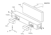
上記の音導波部材142は、図7に示されるように、Y軸方向に延びる管状部材であり、音発生部141j(j=1,2)の-X方向側に配置される。音導波部材142には、音発生部141jとの対向位置に、スピーカ146jから出力された音を取り込むための開口142Ojが形成されている。音導波部材142は、開口142Ojから取り込まれた音をY軸方向に導波し、Y軸方向の両端部の開口から出力する。
なお、音導波部材142は、不図示の固定部材により、車体に固定される。
上記の遮音部材143は、図7に示されるように、吸音性を有する柔軟部材であり、音導波部材142の-X方向側であって、音導波部材142と車室との間に配置される。この遮音部材143は、スピーカ146jから出力された音のうち、音導波部材142に取り込まれなかったものの車室への伝搬を防止する。
[動作]
次に、上記のように構成された擬似エンジン音発生装置100の動作について、音出力部140の動作に主に着目して説明する。
次に、上記のように構成された擬似エンジン音発生装置100の動作について、音出力部140の動作に主に着目して説明する。
擬似エンジン音発生装置100では、取得部110が、アクセル情報センサ910から送られた測定信号AASと、回転数情報センサ920から送られた測定信号ERSとを受ける。引き続き、取得部110は、測定信号AASをデジタル処理部120で処理可能な信号形態を有するアクセル情報ARに変換するとともに、測定信号ERSをデジタル処理部120で処理可能な形態を有する回転数情報ERに変換する。そして、取得部110は、アクセル情報AR及び回転数情報ERをデジタル処理部120へ送る(図1参照)。
デジタル処理部120では、生成部122が、アクセル情報AR及び回転数情報ERを受ける。生成部122は、アクセル情報AR及び回転数情報ERとの組み合わせに関連付けて記憶部121内の波形テーブルWFTに登録された波形パターンのデータWFDを読み取る。次に、生成部122が、新たに読み取られた波形パターンが現時点における波形パターンから変化しているか否かを判定することにより、波形パターンを変化させるべきか否かを判定する。
当該判定が否定的であった場合には、生成部122は、現時点において採用している波形パターンに対応する擬似エンジン音データPEDの生成を継続する。そして、生成部122は、生成された擬似エンジン音データPEDをHPF123及びLPF124へ送る(図2参照)。
一方、当該判定の結果が肯定的であった場合には、生成部122が、新たに読み取られた波形パターンに基づいた擬似エンジン音信号PEDの生成を開始する。そして、生成部122は、生成された擬似エンジン音データPEDをHPF123及びLPF124へ送る(図2参照)。
HPF123は、擬似エンジン音データPEDにおける所定周波数FCよりも高い周波数成分を通過させ、高音成分データPEDHとして、アナログ処理部130へ送る。また、LPF124は、擬似エンジン音データPEDにおける所定周波数FCよりも低い周波数成分を通過させ、低音成分データPEDLとして、アナログ処理部130へ送る(図2参照)。
アナログ処理部130では、高音成分データPEDHがDA変換された後にパワー増幅されて、高音成分出力信号AOSHが生成される。また、アナログ処理部130では、低音成分データPEDLがDA変換された後にパワー増幅されて、低音成分出力信号AOSLが生成される。そして、アナログ処理部130は、生成された高音成分出力信号AOSH及び低音成分出力信号AOSLを音出力部140へ送る(図1参照)。
音出力部140では、音発生部141j(j=1,2)のそれぞれのスピーカ146jが、高音成分出力信号AOSHを受ける。また、音出力部140では、音発生部141j(j=1,2)のそれぞれの振動アクチュエータ145jが、低音成分出力信号AOSLを受ける(図5参照)。
高音成分出力信号AOSHを受けたスピーカ146jは、高音成分出力信号AOSHに従って擬似エンジン音の高音成分を、-X方向側(車体本体側)へ向けて出力する。こうして、スピーカ146jから出力された音の大部分は、開口142Ojから音導波部材142の内部に取り込まれる。こうして取り込まれた音は、音導波部材142の内部空間内をY軸方向(車両CRの幅方向)に沿って導波された後、音導波部材142におけるY軸方向の両端部の開口から、車外へ向けて出力される。この結果、擬似エンジン音の高音成分の大部分が、車内にこもることなく、車外に出力される。
なお、スピーカ146jから出力された音のうちで音導波部材142の内部に取り込まれなかった部分は、車室へ向かって進行するが、その進行が遮音部材143により遮断される。この結果、擬似エンジン音の高音成分の車室への到達量の減少が図られる。
低音成分出力信号AOSLを受けた振動アクチュエータ145jは、低音成分出力信号AOSLに従って振動する。この結果、振動アクチュエータ145jが固定されているフロントバンパーBNFが振動し、車外へ向かう擬似エンジン音の低音成分が発生する。また、フロントバンパーBNFの振動により、フロントバンパーBNFと直接又は間接的に結合された車両の部分が振動し、それらの部分においても擬似エンジン音の低音成分が発生する。
なお、フロントバンパーBNF等で発生し、車室へ向けて進行する擬似エンジン音の低音成分の多くが、遮音部材143により遮断される。この結果、擬似エンジン音の低音成分の多くの車室への到達量の減少が図られる。
以上説明したように、本実施形態では、取得部110により取得された車両の走行情報に基づいて、生成部122が擬似エンジン音データPEDを生成する。引き続き、HPF123及びLPF124により、擬似エンジン音データPEDが高音成分データPEDHと低音成分データPEDLとに分離された後、アナログ処理部130を介することにより、高音成分出力信号AOSH及び低音成分出力信号AOSLが生成される。
そして、低音成分出力信号AOSLに従って、振動アクチュエータ145jがフロントバンパーBNFを振動させ、車外へ向かう擬似エンジン音の低音成分が発生する。このため、ガソリン車におけるエンジンに近い位置で擬似エンジン音の低音成分を発生させることができるとともに、車両内にこもらせることなく、効率的に擬似エンジン音の低音成分を車外へ出力することができる。
また、フロントバンパーBNFの振動により、フロントバンパーBNFと直接又は間接的に結合された車両の部分が振動し、それらの部分においても擬似エンジン音の低音成分が発生する。このため、ガソリン車におけるエンジンの動作に伴うエンジン音と同様の態様で、擬似エンジン音の低音成分を車外へ出力することができる。
したがって、本実施形態によれば、車両CRの走行状態に対応した擬似エンジン音を適切に車外へ出力することができる。
また、上記の実施形態では、音発生部141j(j=1,2)を熱硬化性樹脂からなる接着部材150を介してフロントバンパーBNFに固定するようにしているので、車種によるフロントバンパーBNFの形状の相違にかかわらず、音発生部141jをフロントバンパーBNFに固定することができる。
また、本実施形態では、フロントバンパーBNF付近に配置されたスピーカ146jが、車両の後方へ向けて擬似エンジン音の高音成分を出力する。こうして出力された擬似エンジン音の高音成分の大部分を、開口142Ojを介して音導波部材142の内部に取り込んだ後、音導波部材142により、音導波部材142の内部空間内を車両CRの幅方向に沿って導波し、車両CRの側方から車外へ向けて出力する。このため、ガソリン車におけるエンジンに近い位置で擬似エンジン音の高音成分を発生させることができるとともに、車両内にこもらせることなく、効率的に擬似エンジン音の高音成分を車外へ出力することができる。
また、本実施形態では、擬似エンジン音の発生源と車室との間に遮音部材143を配置している。このため、車室へ向かう擬似エンジン音の多くを遮断でき、車室内への擬似エンジン音の浸入を防止することができる。
[実施形態の変形]
本発明は、上記の実施形態に限定されるものではなく、様々な変形が可能である。
本発明は、上記の実施形態に限定されるものではなく、様々な変形が可能である。
例えば、上記の実施形態では、スピーカ146j(j=1,2)としてコーン型スピーカを例示したが、平面スピーカを採用することもできる。
また、上記の実施形態では、音発生部141j(j=1,2)のそれぞれは、振動アクチュエータ145jとスピーカ146jを備えることとしたが、スピーカ146jは備えていなくても良い。この場合は、振動アクチュエータ145jが、アナログ処理部130から送られた低音及び高音の出力信号を受け、これらの信号に従ってフロントバンパーBNFを振動させる。そして、音導波部材142は、開口142Ojによって、フロントバンパーBNFの振動により発生した音波を取り込み、Y軸方向の両端部の開口から出力する。
また、上記の実施形態では、音発生部141j(j=1,2)をフロントバンパーBNFにのみ固定するようにしたが、リアバンパーBNRにも固定するようにすることもできる。
また、上記の実施形態では、接着部材150として熱硬化性樹脂を採用したが、光硬化性樹脂や熱可塑性樹脂を採用することもできる。
また、上記の実施形態では、音発生部141の数を2個としたが、1個であってもよいし、3個以上であってもよい。
また、上記の実施形態では、車外へ出力する音を擬似エンジン音としたが、他の種類の擬似音としたり、他の種類の擬似音を擬似エンジン音に重畳させたりしてもよい。
また、上記の実施形態では、音導波部材142を車両部品とは別途に用意することにしたが、例えば、車両部品の一つであるリーンフォースが管状であれば、当該リーンフォースに開口142Ojを形成し、音導波部材142として利用してもよい。
また、上記の実施形態では、擬似エンジン音信号を高音成分出力信号AOSH及び低音成分出力信号AOSLに分離するようにしたが、擬似エンジン音信号そのものを、音発生部141j(j=1,2)へ供給するようにしてもよい。
また、上記の実施形態では、擬似エンジン音データの生成に際して参照する車両CRの走行情報として、アクセル情報及び回転数情報を採用したが、これらの情報に代えて、又は、これらの情報に加えて、車速情報、加速度情報、イグニッションスイッチ情報等を参照するようにしてもよい。
Claims (6)
- バンパーを有する車両に搭載される擬似音発生装置であって、
前記車両の車速を含む走行情報を取得する取得部と;
前記取得された走行情報に基づいて、擬似音信号を生成する生成部と;
前記バンパーの前記車両の本体側表面上に設置され、前記生成された擬似音信号に従って前記バンパーを振動させる振動アクチュエータと;
を備えることを特徴とする擬似音発生装置。 - 前記振動アクチュエータは、熱硬化性の接着層を介して、前記バンパーの前記車両の本体側表面上に固定される、ことを特徴とする請求項1に記載の擬似音発生装置。
- 音波を取り込む開口が形成されるとともに、前記開口から取り込んだ音波を車両の進行方向に対して垂直な方向へ伝達し、両端の開口から出力する管状導波部材を更に備え、
前記管状導波部材は、前記音波を取り込む開口により、前記バンパーの振動により発生する音波を取り込む、
ことを特徴とする請求項1又は2に記載の擬似音発生装置。 - 前記バンパーの前記車両の本体側近傍に設置され、前記生成された擬似音信号に従って、前記車両の本体側へ向けて音を出力する少なくとも1つのスピーカを更に備え、
前記管状導波部材は、前記音波を取り込む開口により、前記スピーカのそれぞれにより生成された音波を取り込む、
ことを特徴とする請求項3に記載の擬似音発生装置。 - 前記バンパーと前記車両の車室との間に配置され、前記振動アクチュエータの振動により発生した擬似音の前記車室内への侵入を抑制する遮音部材を更に備える、ことを特徴とする請求項1~4のいずれか一項に記載の擬似音発生装置。
- バンパーを有する車両に搭載され、前記バンパーの前記車両の本体側表面上に設置され、受信した擬似音信号に従って前記バンパーを振動させる振動アクチュエータを備える擬似音発生装置において使用される擬似音発生方法であって、
前記車両の車速を含む走行情報を取得する取得工程と;
前記取得された走行情報に基づいて擬似音信号を生成する生成工程と;
前記生成された擬似音信号に従って前記振動アクチュエータを振動させることにより、前記バンパーを振動させる擬似音出力工程と;
を備えることを特徴とする擬似音発生方法。
Priority Applications (2)
| Application Number | Priority Date | Filing Date | Title |
|---|---|---|---|
| JP2011553631A JP4955839B2 (ja) | 2010-03-10 | 2010-03-10 | 擬似音発生装置及び擬似音発生方法 |
| PCT/JP2010/053960 WO2011111177A1 (ja) | 2010-03-10 | 2010-03-10 | 擬似音発生装置及び擬似音発生方法 |
Applications Claiming Priority (1)
| Application Number | Priority Date | Filing Date | Title |
|---|---|---|---|
| PCT/JP2010/053960 WO2011111177A1 (ja) | 2010-03-10 | 2010-03-10 | 擬似音発生装置及び擬似音発生方法 |
Publications (1)
| Publication Number | Publication Date |
|---|---|
| WO2011111177A1 true WO2011111177A1 (ja) | 2011-09-15 |
Family
ID=44563022
Family Applications (1)
| Application Number | Title | Priority Date | Filing Date |
|---|---|---|---|
| PCT/JP2010/053960 Ceased WO2011111177A1 (ja) | 2010-03-10 | 2010-03-10 | 擬似音発生装置及び擬似音発生方法 |
Country Status (2)
| Country | Link |
|---|---|
| JP (1) | JP4955839B2 (ja) |
| WO (1) | WO2011111177A1 (ja) |
Cited By (4)
| Publication number | Priority date | Publication date | Assignee | Title |
|---|---|---|---|---|
| JP2013189054A (ja) * | 2012-03-13 | 2013-09-26 | Aisin Seiki Co Ltd | バンパ装置 |
| JP2022170255A (ja) * | 2021-04-28 | 2022-11-10 | ヤマハ株式会社 | 信号生成装置、情報生成装置、信号生成方法および情報生成方法 |
| JP2023139441A (ja) * | 2022-03-22 | 2023-10-04 | ダイハツ工業株式会社 | 車両用音響装置 |
| JP2024057939A (ja) * | 2022-10-13 | 2024-04-25 | 豊田合成株式会社 | 車両の音出力装置 |
Families Citing this family (1)
| Publication number | Priority date | Publication date | Assignee | Title |
|---|---|---|---|---|
| JP6341257B2 (ja) * | 2016-11-10 | 2018-06-13 | マツダ株式会社 | バーグラアラーム用サイレン |
Citations (5)
| Publication number | Priority date | Publication date | Assignee | Title |
|---|---|---|---|---|
| JPH0732948A (ja) * | 1993-07-20 | 1995-02-03 | Toyota Motor Corp | 電気自動車用疑似走行音発生装置 |
| JPH09500448A (ja) * | 1993-07-09 | 1997-01-14 | ジーイーシー マルコニ リミテッド | 音響送信および受信装置 |
| JP2004136831A (ja) * | 2002-10-21 | 2004-05-13 | Takumakkusu:Kk | 音響発生装置および自動車 |
| JP2007283809A (ja) * | 2006-04-13 | 2007-11-01 | Anden | 車両周辺に対して警報を発する警報音発生装置 |
| JP2008162477A (ja) * | 2006-12-28 | 2008-07-17 | Toyota Motor Corp | 車両用接近告知装置 |
-
2010
- 2010-03-10 WO PCT/JP2010/053960 patent/WO2011111177A1/ja not_active Ceased
- 2010-03-10 JP JP2011553631A patent/JP4955839B2/ja not_active Expired - Fee Related
Patent Citations (5)
| Publication number | Priority date | Publication date | Assignee | Title |
|---|---|---|---|---|
| JPH09500448A (ja) * | 1993-07-09 | 1997-01-14 | ジーイーシー マルコニ リミテッド | 音響送信および受信装置 |
| JPH0732948A (ja) * | 1993-07-20 | 1995-02-03 | Toyota Motor Corp | 電気自動車用疑似走行音発生装置 |
| JP2004136831A (ja) * | 2002-10-21 | 2004-05-13 | Takumakkusu:Kk | 音響発生装置および自動車 |
| JP2007283809A (ja) * | 2006-04-13 | 2007-11-01 | Anden | 車両周辺に対して警報を発する警報音発生装置 |
| JP2008162477A (ja) * | 2006-12-28 | 2008-07-17 | Toyota Motor Corp | 車両用接近告知装置 |
Cited By (7)
| Publication number | Priority date | Publication date | Assignee | Title |
|---|---|---|---|---|
| JP2013189054A (ja) * | 2012-03-13 | 2013-09-26 | Aisin Seiki Co Ltd | バンパ装置 |
| JP2022170255A (ja) * | 2021-04-28 | 2022-11-10 | ヤマハ株式会社 | 信号生成装置、情報生成装置、信号生成方法および情報生成方法 |
| JP7632035B2 (ja) | 2021-04-28 | 2025-02-19 | ヤマハ株式会社 | 信号生成装置、情報生成装置、信号生成方法および情報生成方法 |
| JP2023139441A (ja) * | 2022-03-22 | 2023-10-04 | ダイハツ工業株式会社 | 車両用音響装置 |
| JP7839668B2 (ja) | 2022-03-22 | 2026-04-02 | ダイハツ工業株式会社 | 車両用音響装置 |
| JP2024057939A (ja) * | 2022-10-13 | 2024-04-25 | 豊田合成株式会社 | 車両の音出力装置 |
| JP7797997B2 (ja) | 2022-10-13 | 2026-01-14 | 豊田合成株式会社 | 車両の音出力装置 |
Also Published As
| Publication number | Publication date |
|---|---|
| JP4955839B2 (ja) | 2012-06-20 |
| JPWO2011111177A1 (ja) | 2013-06-27 |
Similar Documents
| Publication | Publication Date | Title |
|---|---|---|
| JP5029703B2 (ja) | 車両存在報知装置 | |
| JP2014015187A (ja) | 車両存在通報装置 | |
| CN102291653B (zh) | 车辆存在通知装置 | |
| JP5206762B2 (ja) | 車両用警報装置 | |
| CN202106908U (zh) | 行人保护装置 | |
| US12377782B2 (en) | Battery electric vehicle active sound and vibration enhancement systems | |
| JP2009159120A (ja) | 自動車用スピーカー | |
| JP2013071516A (ja) | 車両存在通報装置 | |
| JP2013166538A (ja) | 車両存在通報装置 | |
| WO2011141982A1 (ja) | 音出力装置及び音出力方法 | |
| JP4955839B2 (ja) | 擬似音発生装置及び擬似音発生方法 | |
| JP2007283809A (ja) | 車両周辺に対して警報を発する警報音発生装置 | |
| JP2013216168A (ja) | 車両存在通報装置 | |
| JP2013244895A (ja) | 車両存在通報装置 | |
| JP2013246351A (ja) | 車両存在通報装置 | |
| JP5750994B2 (ja) | 車輌用の警報音発生装置 | |
| US20140121864A1 (en) | Vehicle presence notification system | |
| WO2012053043A1 (ja) | 音出力装置及び車両想起音発生方法 | |
| JP2014015186A (ja) | 車両存在通報装置 | |
| JP5853584B2 (ja) | 車輌の存在報知システム | |
| JP5287888B2 (ja) | 音波発生装置 | |
| JP2012049653A (ja) | 発音装置及び車両存在報知装置 | |
| JP2004015566A (ja) | 車載用スピーカ | |
| JP6059524B2 (ja) | ハイブリッド車両の走行音制御装置 | |
| US8823501B2 (en) | Vehicle presence notification apparatus |
Legal Events
| Date | Code | Title | Description |
|---|---|---|---|
| 121 | Ep: the epo has been informed by wipo that ep was designated in this application |
Ref document number: 10847407 Country of ref document: EP Kind code of ref document: A1 |
|
| WWE | Wipo information: entry into national phase |
Ref document number: 2011553631 Country of ref document: JP |
|
| NENP | Non-entry into the national phase |
Ref country code: DE |
|
| 122 | Ep: pct application non-entry in european phase |
Ref document number: 10847407 Country of ref document: EP Kind code of ref document: A1 |