WO2011111161A1 - 車両の制御装置 - Google Patents
車両の制御装置 Download PDFInfo
- Publication number
- WO2011111161A1 WO2011111161A1 PCT/JP2010/053859 JP2010053859W WO2011111161A1 WO 2011111161 A1 WO2011111161 A1 WO 2011111161A1 JP 2010053859 W JP2010053859 W JP 2010053859W WO 2011111161 A1 WO2011111161 A1 WO 2011111161A1
- Authority
- WO
- WIPO (PCT)
- Prior art keywords
- engine
- operating point
- temperature
- wall
- cylinders
- Prior art date
- Legal status (The legal status is an assumption and is not a legal conclusion. Google has not performed a legal analysis and makes no representation as to the accuracy of the status listed.)
- Ceased
Links
Images





Classifications
-
- F—MECHANICAL ENGINEERING; LIGHTING; HEATING; WEAPONS; BLASTING
- F02—COMBUSTION ENGINES; HOT-GAS OR COMBUSTION-PRODUCT ENGINE PLANTS
- F02D—CONTROLLING COMBUSTION ENGINES
- F02D29/00—Controlling engines, such controlling being peculiar to the devices driven thereby, the devices being other than parts or accessories essential to engine operation, e.g. controlling of engines by signals external thereto
- F02D29/02—Controlling engines, such controlling being peculiar to the devices driven thereby, the devices being other than parts or accessories essential to engine operation, e.g. controlling of engines by signals external thereto peculiar to engines driving vehicles; peculiar to engines driving variable pitch propellers
-
- F—MECHANICAL ENGINEERING; LIGHTING; HEATING; WEAPONS; BLASTING
- F16—ENGINEERING ELEMENTS AND UNITS; GENERAL MEASURES FOR PRODUCING AND MAINTAINING EFFECTIVE FUNCTIONING OF MACHINES OR INSTALLATIONS; THERMAL INSULATION IN GENERAL
- F16H—GEARING
- F16H61/00—Control functions within control units of change-speed- or reversing-gearings for conveying rotary motion ; Control of exclusively fluid gearing, friction gearing, gearings with endless flexible members or other particular types of gearing
- F16H61/66—Control functions within control units of change-speed- or reversing-gearings for conveying rotary motion ; Control of exclusively fluid gearing, friction gearing, gearings with endless flexible members or other particular types of gearing specially adapted for continuously variable gearings
- F16H61/662—Control functions within control units of change-speed- or reversing-gearings for conveying rotary motion ; Control of exclusively fluid gearing, friction gearing, gearings with endless flexible members or other particular types of gearing specially adapted for continuously variable gearings with endless flexible members
- F16H61/66254—Control functions within control units of change-speed- or reversing-gearings for conveying rotary motion ; Control of exclusively fluid gearing, friction gearing, gearings with endless flexible members or other particular types of gearing specially adapted for continuously variable gearings with endless flexible members controlling of shifting being influenced by a signal derived from the engine and the main coupling
- F16H61/66259—Control functions within control units of change-speed- or reversing-gearings for conveying rotary motion ; Control of exclusively fluid gearing, friction gearing, gearings with endless flexible members or other particular types of gearing specially adapted for continuously variable gearings with endless flexible members controlling of shifting being influenced by a signal derived from the engine and the main coupling using electrical or electronical sensing or control means
-
- F—MECHANICAL ENGINEERING; LIGHTING; HEATING; WEAPONS; BLASTING
- F02—COMBUSTION ENGINES; HOT-GAS OR COMBUSTION-PRODUCT ENGINE PLANTS
- F02B—INTERNAL-COMBUSTION PISTON ENGINES; COMBUSTION ENGINES IN GENERAL
- F02B23/00—Other engines characterised by special shape or construction of combustion chambers to improve operation
- F02B23/08—Other engines characterised by special shape or construction of combustion chambers to improve operation with positive ignition
- F02B23/10—Other engines characterised by special shape or construction of combustion chambers to improve operation with positive ignition with separate admission of air and fuel into cylinder
- F02B2023/106—Tumble flow, i.e. the axis of rotation of the main charge flow motion is horizontal
-
- F—MECHANICAL ENGINEERING; LIGHTING; HEATING; WEAPONS; BLASTING
- F02—COMBUSTION ENGINES; HOT-GAS OR COMBUSTION-PRODUCT ENGINE PLANTS
- F02B—INTERNAL-COMBUSTION PISTON ENGINES; COMBUSTION ENGINES IN GENERAL
- F02B75/00—Other engines
- F02B75/12—Other methods of operation
- F02B2075/125—Direct injection in the combustion chamber for spark ignition engines, i.e. not in pre-combustion chamber
-
- F—MECHANICAL ENGINEERING; LIGHTING; HEATING; WEAPONS; BLASTING
- F02—COMBUSTION ENGINES; HOT-GAS OR COMBUSTION-PRODUCT ENGINE PLANTS
- F02B—INTERNAL-COMBUSTION PISTON ENGINES; COMBUSTION ENGINES IN GENERAL
- F02B23/00—Other engines characterised by special shape or construction of combustion chambers to improve operation
- F02B23/08—Other engines characterised by special shape or construction of combustion chambers to improve operation with positive ignition
- F02B23/10—Other engines characterised by special shape or construction of combustion chambers to improve operation with positive ignition with separate admission of air and fuel into cylinder
- F02B23/104—Other engines characterised by special shape or construction of combustion chambers to improve operation with positive ignition with separate admission of air and fuel into cylinder the injector being placed on a side position of the cylinder
-
- F—MECHANICAL ENGINEERING; LIGHTING; HEATING; WEAPONS; BLASTING
- F02—COMBUSTION ENGINES; HOT-GAS OR COMBUSTION-PRODUCT ENGINE PLANTS
- F02D—CONTROLLING COMBUSTION ENGINES
- F02D41/00—Electrical control of supply of combustible mixture or its constituents
- F02D41/0002—Controlling intake air
- F02D2041/0015—Controlling intake air for engines with means for controlling swirl or tumble flow, e.g. by using swirl valves
-
- F—MECHANICAL ENGINEERING; LIGHTING; HEATING; WEAPONS; BLASTING
- F02—COMBUSTION ENGINES; HOT-GAS OR COMBUSTION-PRODUCT ENGINE PLANTS
- F02D—CONTROLLING COMBUSTION ENGINES
- F02D2200/00—Input parameters for engine control
- F02D2200/02—Input parameters for engine control the parameters being related to the engine
- F02D2200/021—Engine temperature
-
- F—MECHANICAL ENGINEERING; LIGHTING; HEATING; WEAPONS; BLASTING
- F16—ENGINEERING ELEMENTS AND UNITS; GENERAL MEASURES FOR PRODUCING AND MAINTAINING EFFECTIVE FUNCTIONING OF MACHINES OR INSTALLATIONS; THERMAL INSULATION IN GENERAL
- F16H—GEARING
- F16H61/00—Control functions within control units of change-speed- or reversing-gearings for conveying rotary motion ; Control of exclusively fluid gearing, friction gearing, gearings with endless flexible members or other particular types of gearing
- F16H61/02—Control functions within control units of change-speed- or reversing-gearings for conveying rotary motion ; Control of exclusively fluid gearing, friction gearing, gearings with endless flexible members or other particular types of gearing characterised by the signals used
- F16H61/0202—Control functions within control units of change-speed- or reversing-gearings for conveying rotary motion ; Control of exclusively fluid gearing, friction gearing, gearings with endless flexible members or other particular types of gearing characterised by the signals used the signals being electric
- F16H61/0204—Control functions within control units of change-speed- or reversing-gearings for conveying rotary motion ; Control of exclusively fluid gearing, friction gearing, gearings with endless flexible members or other particular types of gearing characterised by the signals used the signals being electric for gearshift control, e.g. control functions for performing shifting or generation of shift signal
- F16H61/0213—Control functions within control units of change-speed- or reversing-gearings for conveying rotary motion ; Control of exclusively fluid gearing, friction gearing, gearings with endless flexible members or other particular types of gearing characterised by the signals used the signals being electric for gearshift control, e.g. control functions for performing shifting or generation of shift signal characterised by the method for generating shift signals
Definitions
- the present invention relates to a vehicle control device, and more particularly to a temperature rise of a wall portion formed between engine cylinders in a vehicle equipped with a speed change mechanism capable of changing a gear ratio so that an engine operating point comes to a predetermined operating point
- the present invention relates to a control device for a vehicle for suppressing the vehicle.
- Patent Document 1 discloses a technique that is considered to be related to the present invention in that the speed ratio is set so that the operating point is on the optimum fuel consumption line.
- the temperature of the wall portion formed between the cylinders is particularly likely to rise due to the structure.
- the temperature of the wall portion formed between the cylinders shown in (a) is compared with the temperature of the cylinder wall portion formed on the engine intake side shown in (b). High in all engine operating conditions. Further, when the engine operating state changes from the low rotation and low load operation region to the high rotation and high load operation region, the temperature shown in (a) is larger than the temperature shown in (b). It is getting higher.
- the rise in the temperature of the wall formed between the cylinders is problematic in that it causes abnormal consumption of engine oil, especially in engines where the temperature of the combustion chamber wall surface is higher, such as engines that perform high-speed combustion. There is a concern that it may occur during high-load operation. Such a temperature rise has a problem in that it hinders improvement in fuel consumption, particularly in an engine that performs high-speed combustion to improve fuel consumption.
- the present invention has been made in view of the above problems, and is formed between cylinders of an engine in a vehicle equipped with a speed change mechanism capable of changing the speed ratio so that the operating point of the engine comes to a predetermined operating point.
- An object of the present invention is to provide a vehicle control device capable of suitably suppressing a temperature rise of a wall portion.
- the present invention for solving the above problems is equipped with an engine having a cylinder block in which a plurality of cylinders are formed, and a speed change mechanism capable of changing a gear ratio so that the operating point of the engine comes to a predetermined operating point.
- the operating point of the engine is at the first operating point and the temperature of the wall formed between adjacent cylinders among the plurality of cylinders is higher than a predetermined temperature, or
- the parameter having a correlation with the temperature of the wall portion is larger than a predetermined value corresponding to the predetermined temperature
- the operating point of the engine maintains the output of the engine and changes the operating state of the engine to the first
- a vehicle control device comprising a control means for performing control for changing the gear ratio so as to come to a second operating point where the rotational speed and load can be lower than the operating point. That.
- the engine includes an intake air introduction unit that introduces intake air so as to generate a swirling airflow in the cylinder.
- the temperature rise of the wall portion formed between the cylinders of the engine is suitably suppressed. it can.
- the engine 50 shown in FIGS. 1 and 2 is an in-line four-cylinder in-cylinder direct fuel injection gasoline engine, and includes a cylinder block 51, a cylinder head 52, a piston 53, an intake valve 55, an exhaust valve 56, A spark plug 57 and a fuel injection valve 58 are provided.
- the cylinder block 51 is formed with a plurality of (here, four) cylinders 51a and a water jacket 51b.
- a wall portion 51c is formed between adjacent cylinders among the plurality of cylinders 51a.
- a piston 53 is accommodated in the cylinder 51a.
- a cylinder head 52 is fixed to the upper surface of the cylinder block 51.
- the combustion chamber 54 is formed as a space surrounded by the cylinder block 51, the cylinder head 52 and the piston 53.
- the cylinder head 52 has an intake port 52a and an exhaust port 52b.
- the intake port 52a which is an intake introduction means, guides the intake air S to the combustion chamber 54, and the exhaust port 52b exhausts the gas in the combustion chamber 54.
- the intake air S introduced into the cylinder forms a tumble flow T.
- the cylinder head 52 is provided with intake and exhaust valves 55 and 56 for opening and closing these intake and exhaust ports 52a and 52b.
- the cylinder head 52 is provided with a spark plug 57 with an electrode protruding substantially at the center of the upper portion of the combustion chamber 54. Further, the cylinder head 52 is provided with a fuel injection valve 58 so that the fuel F can be directly injected into the cylinder.
- the engine 50 includes a crank angle sensor 81 for detecting the rotational speed of the engine 50, a water temperature sensor 82 for detecting the cooling water temperature of the engine 50, a temperature sensor 83 for detecting the temperature of the wall 51c, A combustion pressure sensor 84 for detecting the combustion pressure is provided.
- the temperature sensor 83 may be provided only for the wall portion 51c assumed to have the highest temperature among the plurality of wall portions 51c due to the structure of the engine 50, for example.
- FIG. 3 shows a main part of a vehicle on which the engine 50 and related components are mounted.
- the input shaft of the torque converter 61 is connected to the output shaft of the engine 50.
- the torque converter 61 transmits power via a fluid.
- the output shaft of the torque converter 61 is connected to the input shaft of the forward / reverse switching device 62.
- the forward / reverse switching device 62 transmits power between a state in which power is transmitted in the rotational direction in which the vehicle is moved forward, a state in which power is transmitted in the rotational direction in which the vehicle is moved backward, and a neutral state in which power transmission is interrupted.
- the transmission mode can be switched.
- the output shaft of the forward / reverse switching device 62 is connected to the input shaft of the CVT 63.
- the CVT 63 includes a primary pulley 631, a secondary pulley 632, a drive belt 633, a first hydraulic cylinder 634, and a second hydraulic cylinder 635.
- a drive belt 633 is wound around the primary pulley 631 and the secondary pulley 632.
- the primary pulley 631 is provided with a first hydraulic cylinder 634.
- the first hydraulic cylinder 634 changes the groove width of the pulley according to the hydraulic pressure P1.
- the gear ratio can be made continuously variable.
- the CVT 63 that makes the speed ratio variable according to the hydraulic pressure P1 is a speed change mechanism that can set the speed ratio so that the operating point of the engine 50 comes to a predetermined operating point.
- the CVT 63 that continuously varies the speed ratio according to the hydraulic pressure P1 is a speed change mechanism that can set the speed ratio so that the operating point of the engine 50 is on a predetermined operating line.
- the secondary pulley 632 is provided with a second hydraulic cylinder 635.
- the second hydraulic cylinder 635 adjusts the clamping pressure according to the hydraulic pressure P2. This prevents the drive belt 633 from slipping.
- the oil pressures P1 and P2 are both supplied from the oil pressure control circuit 64.
- the output of the engine 50 is transmitted to the primary pulley 631 and then transmitted to the secondary pulley 632 via the drive belt 633 and then output. Then, the output of the engine 50 is transmitted to the drive wheel 67 via the speed reducer 65 and the differential device 66.
- Both the engine ECU 70 and the CVT ECU 71 are provided with a microcomputer comprising a CPU, a ROM, a RAM and the like and an input / output circuit.
- the engine ECU 70 is an electronic control unit mainly for controlling the engine 50
- the CVT ECU 71 is an electronic control unit mainly for controlling the CVT 63.
- the engine ECU 70 and the CVT ECU 71 are communicably connected to each other.
- the engine ECU 70 includes an air flow meter for measuring the intake air amount, an accelerator opening sensor for detecting the accelerator opening, an intake air
- Various sensors and switches 90 including an intake pressure sensor for detecting the pipe pressure, an exhaust pressure sensor for detecting the exhaust pipe pressure, a knock sensor and the like are electrically connected.
- a hydraulic control circuit 64 is electrically connected to the CVT ECU 71 as a control target.
- the ROM is configured to store a program describing various processes executed by the CPU, map data, and the like. When the CPU executes a process based on a program stored in the ROM while using a temporary storage area of the RAM as necessary, the ECUs 70 and 71 have various control means, determination means, detection means, calculation means, and the like. Functionally realized.
- determination means for determining whether or not the temperature of the wall 51c is higher than the predetermined temperature ⁇ is functionally realized.
- the determination means is the highest of the temperatures directly detected based on the outputs of the temperature sensor 83 when the operation state of the engine 50 is a predetermined operation state (for example, high rotation and high load).
- the temperature is representatively determined so as to determine whether or not the temperature of the wall 51c is higher than the predetermined temperature ⁇ .
- the predetermined temperature ⁇ is specifically set to an upper limit temperature at which the reliability of the engine 50 can be ensured.
- the determination result of the determination unit is output from the ECU 70 to the ECU 71.
- the determination means may be realized by the ECU 71, for example.
- setting means for setting a gear ratio is functionally realized.
- the setting means specifically sets the gear ratio so that the operating point of the engine 50 is on a predetermined operating line by controlling the hydraulic pressures P1 and P2 with the hydraulic control circuit 64 as a control target. Is realized.
- the setting means is specifically realized to perform a first setting for setting the gear ratio so that the operating point of the engine 50 is on the first operation line A shown in FIG. .
- an operation line that emphasizes acceleration performance, an operation line that can achieve both fuel consumption and acceleration performance, and the like can be applied to the first operation line A. .
- the setting means is implemented as a predetermined operation line so as to perform a second setting for setting the gear ratio so that the operating point of the engine 50 is on the second operation line B shown in FIG.
- the setting means performs the first setting when the temperature of the wall 51c is equal to or lower than the predetermined temperature ⁇ , and performs the second setting when the temperature of the wall 51c is higher than the predetermined temperature ⁇ .
- the ECU 71 functionally realizes a control means for performing control for changing the gear ratio so that the operating point of the engine 50 comes to a predetermined operating point.
- the control means determines that the operating point of the engine 50 is the output of the engine 50 when the operating point of the engine 50 is at the first operating point a and the temperature of the wall 51c is higher than the predetermined temperature ⁇ .
- the control is performed to change the gear ratio so that the operating state of the engine 50 is at the second operating point b where the rotational speed and the load can be lower than the first operating point a while maintaining Is done.
- the first operating point a is specifically the operating point that constitutes the first operating line A
- the second operating point b is specifically configuring the second operating line B.
- the second operation line B is specifically an operation line having an equal output and a lower rotation and a higher load than the first operation line A.
- the control means sets the operating point of the engine 50 to the first operating point a when the operating point of the engine 50 is at the second operating point b and the temperature of the wall 51c is equal to or lower than the predetermined temperature ⁇ . The control for changing the gear ratio is performed so that
- the ECU 70 detects the temperature of the wall 51c (step S1) and determines whether the temperature of the wall 51c is higher than a predetermined temperature ⁇ (step S2). If the determination is affirmative, the ECU 71 determines whether or not the gear ratio setting is the first setting (step S3). If the determination is affirmative, the operating point of the engine 50 is at the first operating point a. Therefore, if an affirmative determination is made in step S3, the ECU 71 performs the second setting (step S4) and changes the gear ratio so that the operating point of the engine 50 is at the second operating point b (step S5). .
- step S2 determines whether or not the speed ratio setting is the second setting (step S6). If the determination is affirmative, the ECU 71 performs the first setting (step S7) and changes the gear ratio so that the operating point of the engine 50 is at the first operating point a (step S8).
- the ECU 71 sets the operating point of the engine 50 to the second operating point b when the operating point of the engine 50 is at the first operating point a and the temperature of the wall 51c is higher than the predetermined temperature ⁇ . Change the gear ratio.
- the first operating point a is an operating point with an equal output and a lower temperature than the second operating point b.
- ECU71 can suppress suitably the temperature rise of the wall part 51c by the point which can suppress the temperature rise of the wall part 51c, without having a bad influence on the output of the engine 50 by this.
- the engine 50 generates a tumble flow T having a tumble ratio of about 1.5 in the cylinder, maintains the generated tumble flow T until the latter half of the compression stroke, and disrupts the atmosphere in the cylinder.
- high-speed combustion is performed by improving the combustion speed.
- the temperature of the combustion gas increases due to the improvement of the combustion speed, and the temperature boundary layer becomes thinner than the swirling airflow, and as a result, the heat transfer coefficient increases, so the combustion chamber 54 The wall temperature becomes higher.
- the higher the rotation speed and the higher the load the greater the amount of heat generated per unit time, and the greater the strength of the swirling airflow, the greater the heat transfer coefficient.
- the temperature rise of the wall 51c is particularly problematic due to such circumstances.
- the ECU 71 capable of suppressing the temperature of the wall 51c as described above is suitable for the engine 50 in which the temperature increase of the wall 51c is particularly problematic.
- the engine 50 that introduces the intake air S so as to generate the tumble flow T in the cylinder, deposits adhere to the intake port 52a and the intake valve 55 due to changes over time, so that the flow velocity of the tumble flow T is compared with the initial state. May increase.
- the combustion speed increases due to the increase in the flow velocity of the tumble flow T
- the combustion gas temperature increases as shown in FIG. 6 (a) and the heat transfer as shown in FIG. 6 (b).
- the coefficient increases.
- the wall surface temperature of the combustion chamber 54 increases as compared with the initial case, so that the temperature rise of the wall portion 51 c becomes even more problematic.
- the ECU 71 that can suppress the temperature of the wall 51c as described above is suitable for the engine 50 in which the temperature rise of the wall 51c becomes even more problematic.
- the parameter having a correlation with the temperature of the wall 51c is greater than a predetermined value ⁇ corresponding to the predetermined temperature ⁇ . It may be realized so as to determine whether or not it is large.
- the product of the temperature of the combustion gas and the combustion speed in a predetermined operation state (for example, high rotation and high load) can be applied to this parameter.
- the product of the combustion gas temperature and the combustion speed has a correlation with the temperature of the wall 51c as shown in FIG.
- the combustion gas temperature and the combustion speed can be estimated from various information about the engine 50 such as the intake air amount, the engine speed, the intake and exhaust pipe pressure, and the combustion pressure.
- an ignition timing retard amount that is retarded by a greater degree as the degree of knocking is greater in accordance with the output of the knock sensor in a predetermined operating state (for example, high rotation and high load). You can also.
- the ignition retard amount also has a correlation with the temperature of the wall 51c as shown in FIG.
- the temperature of a portion other than the wall portion 51c in the wall portion of the combustion chamber 54 can be applied to the parameter having a correlation with the temperature of the wall portion 51c.
- the present invention is not limited to this, and various modifications can be made without departing from the scope of the present invention.
- the intake air introduction means is the intake port 52a
- the present invention is not necessarily limited to this, and the intake air introduction means is realized, for example, by an airflow control valve that is provided in the intake port and can control the flow of intake air, or a combination of the airflow control valve and the intake port. May be.
- the swirling airflow is the tumble flow T has been described.
- the present invention is not necessarily limited to this, and the swirling airflow may be, for example, a swirl flow or an oblique tumble flow.
- the control means that is functionally realized by the ECUs 70 and 71 in the above-described embodiments may be realized by hardware such as other electronic control devices or dedicated electronic circuits, or a combination thereof.
Landscapes
- Engineering & Computer Science (AREA)
- General Engineering & Computer Science (AREA)
- Mechanical Engineering (AREA)
- Chemical & Material Sciences (AREA)
- Combustion & Propulsion (AREA)
- Output Control And Ontrol Of Special Type Engine (AREA)
- Control Of Driving Devices And Active Controlling Of Vehicle (AREA)
- Control Of Vehicle Engines Or Engines For Specific Uses (AREA)
- Combined Controls Of Internal Combustion Engines (AREA)
- Control Of Transmission Device (AREA)
Abstract
ECU71は、複数のシリンダ51aが形成されたシリンダブロック51を備えたエンジン50を搭載するとともに、エンジン50の動作点が所定の動作点にくるように変速比を変更可能なCVT63を搭載した車両につき、エンジン50の動作点が第1の動作点aにあり、且つ複数のシリンダ51aのうち、隣り合うシリンダ間に形成される壁部51cの温度が所定温度αよりも大きい場合に、エンジンの動作点が、エンジン50の出力を維持しつつエンジン50の運転状態を第1の動作点aよりも低回転高負荷とすることが可能な第2の動作点bにくるように変速比を変更するための制御を行う。
Description
本発明は車両の制御装置に関し、特にエンジンの動作点が所定の動作点にくるように変速比を変更可能な変速機構を搭載した車両において、エンジンのシリンダ間に形成される壁部の温度上昇を抑制するための車両の制御装置に関する。
従来、例えばCVT(Continuously Variable Transmission)搭載車両やハイブリッド車両など、変速比を連続的に可変とする変速機構を搭載した車両が知られている。かかる車両では、変速比を変更することによりエンジンの動作点をある程度自由に選択することができる。この点、動作点が最適燃費線上にくるように変速比を設定している点で、本発明と関連性があると考えられる技術が例えば特許文献1で開示されている。
ところでエンジンでは構造上、シリンダ間に形成される壁部の温度が特に上昇し易くなっている。具体的には図10に示すように、(a)に示すシリンダ間に形成される壁部の温度は、(b)に示すエンジン吸気側に形成されるシリンダ壁部の温度と比較して、エンジンの運転状態すべてにおいて高くなっている。また、エンジンの運転状態が低回転低負荷の運転領域から高回転高負荷の運転領域に向かって変化する場合、(a)に示す温度は(b)に示す温度と比較してより大きな度合いで高まるようになっている。この点、シリンダ間に形成される壁部の温度上昇は、エンジンオイルの異常消費を招く点で問題があり、特に高速燃焼を行うエンジンなど燃焼室壁面の温度がより高温になるエンジンで高回転高負荷運転時に発生することが懸念される。そして、かかる温度上昇は特に燃費を改善すべく高速燃焼を行うエンジンにおいて、燃費向上の妨げとなる点で問題があった。
そこで本発明は上記課題に鑑みてなされたものであり、エンジンの動作点が所定の動作点にくるように変速比を変更可能な変速機構を搭載した車両において、エンジンのシリンダ間に形成される壁部の温度上昇を好適に抑制可能な車両の制御装置を提供することを目的とする。
上記課題を解決するための本発明は複数のシリンダが形成されたシリンダブロックを備えたエンジンを搭載するとともに、前記エンジンの動作点が所定の動作点にくるように変速比を変更可能な変速機構を搭載した車両につき、前記エンジンの動作点が第1の動作点にあり、且つ前記複数のシリンダのうち、隣り合うシリンダ間に形成される壁部の温度が所定温度よりも大きい場合、または前記壁部の温度と相関関係を有するパラメータが前記所定温度に対応する所定値よりも大きい場合に、前記エンジンの動作点が、前記エンジンの出力を維持しつつ前記エンジンの運転状態を前記第1の動作点よりも低回転高負荷とすることが可能な第2の動作点にくるように前記変速比を変更するための制御を行う制御手段を備えた車両の制御装置である。
また本発明は前記エンジンが、筒内に旋回気流を生成するように吸気を導入する吸気導入手段を備える構成であることが好ましい。
本発明によれば、エンジンの動作点が所定の動作点にくるように変速比を変更可能な変速機構を搭載した車両において、エンジンのシリンダ間に形成される壁部の温度上昇を好適に抑制できる。
以下、本発明を実施するための形態を図面と共に詳細に説明する。
図1、図2に示すエンジン50は直列4気筒の筒内燃料直接噴射式のガソリンエンジンであり、シリンダブロック51と、シリンダヘッド52と、ピストン53と、吸気弁55と、排気弁56と、点火プラグ57と、燃料噴射弁58とを備えている。シリンダブロック51には複数(ここでは4つ)のシリンダ51aとウォータジャケット51bとが形成されている。複数のシリンダ51aのうち、隣り合うシリンダ間には壁部51cが形成されている。シリンダ51a内にはピストン53が収容されている。シリンダブロック51の上面にはシリンダヘッド52が固定されている。燃焼室54はシリンダブロック51、シリンダヘッド52及びピストン53に囲まれた空間として形成されている。
シリンダヘッド52には吸気ポート52aと排気ポート52bとが形成されている。吸気導入手段である吸気ポート52aは燃焼室54に吸気Sを導き、排気ポート52bは燃焼室54のガスを排気する。筒内に導入された吸気Sはタンブル流Tを形成する。シリンダヘッド52にはこれら吸排気ポート52a及び52bを開閉するための吸排気弁55、56が設けられている。またシリンダヘッド52には、燃焼室54の上部略中央に電極を突出させた状態で点火プラグ57が設けられている。さらにシリンダヘッド52には、燃料噴射弁58が筒内に燃料Fを直接噴射できるように設けられている。エンジン50にはエンジン50の回転数を検出するためのクランク角センサ81や、エンジン50の冷却水温を検出するための水温センサ82や、壁部51cの温度を検出するための温度センサ83や、燃焼圧を検出するための燃焼圧センサ84が設けられている。なお、温度センサ83はエンジン50の構造上、例えば複数の壁部51cのうち、最も温度が高くなると想定される壁部51cに対してのみ設けられてもよい。
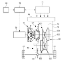
図3はエンジン50および関連する各構成を搭載した車両の要部を示しており、エンジン50の出力軸にはトルクコンバータ61の入力軸が連結されている。トルクコンバータ61は流体を介した動力の伝達を行う。トルクコンバータ61の出力軸には前後進切換装置62の入力軸が連結されている。前後進切換装置62は、車両を前進させる回転方向に動力を伝達する状態と、車両を後進させる回転方向に動力を伝達する状態と、動力の伝達を遮断するニュートラル状態との間で、動力の伝達態様を切換可能に構成されている。前後進切換装置62の出力軸にはCVT63の入力軸が連結されている。
CVT63はプライマリプーリ631と、セカンダリプーリ632と、駆動ベルト633と、第1の油圧シリンダ634と、第2の油圧シリンダ635とを備えている。プライマリプーリ631とセカンダリプーリ632とには駆動ベルト633が巻き掛けられている。プライマリプーリ631には第1の油圧シリンダ634が設けられている。第1の油圧シリンダ634は油圧P1に応じてプーリの溝幅を変更する。そしてこれにより変速比を連続的に可変にすることができる。この点、油圧P1に応じて変速比を可変にするCVT63は、エンジン50の動作点が所定の動作点にくるように変速比を設定可能な変速機構となっている。また油圧P1に応じて変速比を連続的に可変にするCVT63は、さらに具体的にはエンジン50の動作点が所定の動作線上にくるように変速比を設定可能な変速機構となっている。
セカンダリプーリ632には第2の油圧シリンダ635が設けられている。第2の油圧シリンダ635は油圧P2に応じて挟圧力を調整する。そしてこれにより駆動ベルト633の滑りを防止できる。油圧P1、P2はともに油圧制御回路64から供給される。CVT63では、エンジン50の出力がプライマリプーリ631に伝達され、その後駆動ベルト633を介してセカンダリプーリ632に伝達された上で出力される。そしてその後エンジン50の出力は、減速機65および差動装置66を介して駆動輪67に伝達される。
エンジン用ECU70およびCVT用ECU71はともにCPU、ROM、RAM等からなるマイクロコンピュータと入出力回路とを備えている。エンジン用ECU70は主にエンジン50を制御するための電子制御装置であり、CVT用ECU71は主にCVT63を制御するための電子制御装置となっている。エンジン用ECU70とCVT用ECU71とは互いに通信可能に接続されている。
エンジン用ECU70にはクランク角センサ81や水温センサ82や温度センサ83や燃焼圧センサ84のほか、吸入空気量を計測するためのエアフロメータ、アクセル開度を検出するためのアクセル開度センサ、吸気管圧力を検出するための吸気圧センサ、排気管圧力を検出するための排気圧センサ、ノックセンサなどを含む各種のセンサ・スイッチ類90が電気的に接続されている。CVT用ECU71には、油圧制御回路64が制御対象として電気的に接続されている。
ROMはCPUが実行する種々の処理が記述されたプログラムやマップデータなどを格納するための構成である。CPUがROMに格納されたプログラムに基づき、必要に応じてRAMの一時記憶領域を利用しつつ処理を実行することで、ECU70、71では各種の制御手段や判定手段や検出手段や算出手段などが機能的に実現される。
エンジン用ECU70にはクランク角センサ81や水温センサ82や温度センサ83や燃焼圧センサ84のほか、吸入空気量を計測するためのエアフロメータ、アクセル開度を検出するためのアクセル開度センサ、吸気管圧力を検出するための吸気圧センサ、排気管圧力を検出するための排気圧センサ、ノックセンサなどを含む各種のセンサ・スイッチ類90が電気的に接続されている。CVT用ECU71には、油圧制御回路64が制御対象として電気的に接続されている。
ROMはCPUが実行する種々の処理が記述されたプログラムやマップデータなどを格納するための構成である。CPUがROMに格納されたプログラムに基づき、必要に応じてRAMの一時記憶領域を利用しつつ処理を実行することで、ECU70、71では各種の制御手段や判定手段や検出手段や算出手段などが機能的に実現される。
この点、ECU70では、例えば壁部51cの温度が所定温度αよりも大きいか否かを判定する判定手段が機能的に実現される。判定手段は具体的には、エンジン50の運転状態が所定の運転状態(例えば高回転高負荷)である場合に、温度センサ83の出力それぞれに基づき直接的に検出される温度のうち、最も高い温度を代表として、壁部51cの温度が所定温度αよりも大きいか否かを判定するように実現される。また所定温度αは具体的には、エンジン50の信頼性を確保可能な上限温度に設定されている。判定手段の判定結果は、ECU70からECU71に出力される。なお、判定手段は例えばECU71で実現されてもよい。
またECU71では例えば変速比の設定を行う設定手段が機能的に実現される。変速比を設定するにあたり、設定手段は具体的には油圧制御回路64を制御対象として油圧P1、P2を制御することで、エンジン50の動作点が所定の動作線上にくるように変速比の設定を行うよう実現される。
所定の動作線として、設定手段は具体的にはエンジン50の動作点が図4に示す第1の動作線A上にくるように変速比を設定する第1の設定を行うように実現される。第1の動作線Aには、具体的には例えば燃費最適動作線のほか加速性能を重視した動作線や、燃費と加速性能の両立を図ることが可能な動作線などを適用することができる。
また設定手段は所定の動作線として、エンジン50の動作点が図4に示す第2の動作線B上にくるように変速比を設定する第2の設定を行うように実現される。
そして設定手段は壁部51cの温度が所定温度α以下である場合には、第1の設定を行うとともに、壁部51cの温度が所定温度αよりも大きい場合には、第2の設定を行うように実現される。
所定の動作線として、設定手段は具体的にはエンジン50の動作点が図4に示す第1の動作線A上にくるように変速比を設定する第1の設定を行うように実現される。第1の動作線Aには、具体的には例えば燃費最適動作線のほか加速性能を重視した動作線や、燃費と加速性能の両立を図ることが可能な動作線などを適用することができる。
また設定手段は所定の動作線として、エンジン50の動作点が図4に示す第2の動作線B上にくるように変速比を設定する第2の設定を行うように実現される。
そして設定手段は壁部51cの温度が所定温度α以下である場合には、第1の設定を行うとともに、壁部51cの温度が所定温度αよりも大きい場合には、第2の設定を行うように実現される。
またECU71では、エンジン50の動作点が所定の動作点にくるように変速比を変更するための制御を行う制御手段が機能的に実現される。
具体的には制御手段は、エンジン50の動作点が第1の動作点aにあり、且つ壁部51cの温度が所定温度αよりも大きい場合に、エンジン50の動作点が、エンジン50の出力を維持しつつエンジン50の運転状態を第1の動作点aよりも低回転高負荷とすることが可能な第2の動作点bにくるように変速比を変更するための制御を行うよう実現される。
この点、第1の動作点aは具体的には第1の動作線Aを構成する動作点となっており、第2の動作点bは具体的には第2の動作線Bを構成する動作点となっている。したがって、第2の動作線Bは具体的には等出力で第1の動作線Aよりも低回転高負荷となる動作線となっている。
また制御手段は、エンジン50の動作点が第2の動作点bにあり、且つ壁部51cの温度が所定温度α以下である場合には、エンジン50の動作点が第1の動作点aにくるように変速比を変更するための制御を行うよう実現される。
具体的には制御手段は、エンジン50の動作点が第1の動作点aにあり、且つ壁部51cの温度が所定温度αよりも大きい場合に、エンジン50の動作点が、エンジン50の出力を維持しつつエンジン50の運転状態を第1の動作点aよりも低回転高負荷とすることが可能な第2の動作点bにくるように変速比を変更するための制御を行うよう実現される。
この点、第1の動作点aは具体的には第1の動作線Aを構成する動作点となっており、第2の動作点bは具体的には第2の動作線Bを構成する動作点となっている。したがって、第2の動作線Bは具体的には等出力で第1の動作線Aよりも低回転高負荷となる動作線となっている。
また制御手段は、エンジン50の動作点が第2の動作点bにあり、且つ壁部51cの温度が所定温度α以下である場合には、エンジン50の動作点が第1の動作点aにくるように変速比を変更するための制御を行うよう実現される。
次にECU70、71の動作を図5に示すフローチャートを用いて説明する。ECU70は壁部51cの温度を検出するとともに(ステップS1)、壁部51cの温度が所定温度αよりも大きいか否かを判定する(ステップS2)。肯定判定であれば、ECU71は変速比の設定が第1の設定であるか否かを判定する(ステップS3)。肯定判定であれば、エンジン50の動作点が第1の動作点aにあることになる。このためステップS3で肯定判定であれば、ECU71は第2の設定を行うとともに(ステップS4)、エンジン50の動作点が第2の動作点bにくるように変速比を変更する(ステップS5)。一方、ステップS2で否定判定であれば、ECU71は変速比の設定が第2の設定であるか否かを判定する(ステップS6)。そして肯定判定であれば、ECU71は第1の設定を行うとともに(ステップS7)、エンジン50の動作点が第1の動作点aにくるように変速比を変更する(ステップS8)。
次にECU71の作用効果について説明する。ECU71は、エンジン50の動作点が第1の動作点aにあり、且つ壁部51cの温度が所定温度αよりも大きい場合に、エンジン50の動作点が第2の動作点bにくるように変速比を変更する。この点、図4に示すように第1の動作点aは第2の動作点bと比較して等出力で、且つ温度が低い動作点となっている。このためECU71は、これによりエンジン50の出力に悪影響を及ぼすことなく、壁部51cの温度上昇を抑制できる点で、壁部51cの温度上昇を好適に抑制できる。
またエンジン50では、タンブル比1.5程度のタンブル流Tを筒内に生成し、生成したタンブル流Tを圧縮行程後半まで維持するとともに崩壊させることで筒内の雰囲気に乱れを生じさせ、これにより燃焼速度の向上を図ることで高速燃焼が行われる。この点、高速燃焼を行うエンジン50では、燃焼速度の向上で燃焼ガスの温度が高まることや、旋回気流より温度境界層が薄くなり、この結果、熱伝達係数が大きくなることから、燃焼室54壁面の温度がより高温になる。また高速燃焼を行うエンジン50では。回転数が大きく負荷が高い場合ほど、単位時間あたりの発熱量が増大するとともに、旋回気流の強さが増すことで熱伝達係数がさらに大きくなる。すなわち高速燃焼を行うエンジン50では、かかる事情により壁部51cの温度上昇が特に問題となる。
この点、上述のようにして壁部51cの温度を抑制できるECU71は、このように壁部51cの温度上昇が特に問題となるエンジン50に好適である。
この点、上述のようにして壁部51cの温度を抑制できるECU71は、このように壁部51cの温度上昇が特に問題となるエンジン50に好適である。
さらに筒内にタンブル流Tを生成するように吸気Sを導入するエンジン50では、経時変化により吸気ポート52aや吸気弁55にデポジットが付着することで、タンブル流Tの流速が初期の状態と比較して高まる可能性がある。そしてこの場合には、タンブル流Tの流速増加に起因して燃焼速度が高まることから、図6(a)に示すように燃焼ガス温度が高まるとともに、図6(b)に示すように熱伝達係数が大きくなる。そしてこの結果、図7に示すように燃焼室54の壁面温度が初期の場合と比較して高まることから壁部51cの温度上昇がより一層問題となる。
この点、上述のようにして壁部51cの温度を抑制できるECU71は、このように壁部51cの温度上昇がより一層問題となるエンジン50に好適である。
この点、上述のようにして壁部51cの温度を抑制できるECU71は、このように壁部51cの温度上昇がより一層問題となるエンジン50に好適である。
なお、判定手段は壁部51cの温度が所定温度αよりも大きいか否かを判定する代わりに、例えば壁部51cの温度と相関関係を有するパラメータが所定温度αに対応する所定値βよりも大きいか否かを判定するように実現されてもよい。
この点、かかるパラメータには具体的には例えば、所定の運転状態(例えば高回転高負荷)における燃焼ガスの温度と燃焼速度との積を適用することができる。かかる燃焼ガス温度と燃焼速度との積は、図8に示すように壁部51cの温度と相関関係を有している。この場合、燃焼ガス温度や燃焼速度は例えば吸入空気量やエンジン回転数や吸排気管圧力などのエンジン50についての各種の情報と燃焼圧とから推定するようにすることができる。
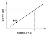
またかかるパラメータには、例えば所定の運転状態(例えば高回転高負荷)におけるノックセンサの出力に応じて、ノッキングの度合いが大きいほどより大きな度合いで遅角される点火時期遅角量を適用することもできる。かかる点火遅角量も、図9に示すように壁部51cの温度と相関関係を有している。
このほか壁部51cの温度と相関関係を有するパラメータには、例えば燃焼室54の壁部のうち、壁部51c以外の部分の温度を適用することなどもできる。
この点、かかるパラメータには具体的には例えば、所定の運転状態(例えば高回転高負荷)における燃焼ガスの温度と燃焼速度との積を適用することができる。かかる燃焼ガス温度と燃焼速度との積は、図8に示すように壁部51cの温度と相関関係を有している。この場合、燃焼ガス温度や燃焼速度は例えば吸入空気量やエンジン回転数や吸排気管圧力などのエンジン50についての各種の情報と燃焼圧とから推定するようにすることができる。
またかかるパラメータには、例えば所定の運転状態(例えば高回転高負荷)におけるノックセンサの出力に応じて、ノッキングの度合いが大きいほどより大きな度合いで遅角される点火時期遅角量を適用することもできる。かかる点火遅角量も、図9に示すように壁部51cの温度と相関関係を有している。
このほか壁部51cの温度と相関関係を有するパラメータには、例えば燃焼室54の壁部のうち、壁部51c以外の部分の温度を適用することなどもできる。
上述した実施例は本発明の好適な実施の例である。但し、これに限定されるものではなく、本発明の要旨を逸脱しない範囲内において種々変形実施可能である。
例えば上述した実施例では吸気導入手段が吸気ポート52aである場合について説明した。しかしながら、本発明においては必ずしもこれに限られず、吸気導入手段は、例えば吸気ポート内に設けられ、吸気の流れを制御可能な気流制御弁や、気流制御弁と吸気ポートとの組み合わせなどによって実現されてもよい。
また例えば上述した実施例では旋回気流がタンブル流Tである場合について説明した。しかしながら、本発明においては必ずしもこれに限られず、旋回気流は例えばスワール流や斜めタンブル流などであってもよい。
また例えば上述した実施例でECU70、71によって機能的に実現される制御手段は、その他の電子制御装置や専用の電子回路などのハードウェアやこれらの組み合わせによって実現されてもよい。
例えば上述した実施例では吸気導入手段が吸気ポート52aである場合について説明した。しかしながら、本発明においては必ずしもこれに限られず、吸気導入手段は、例えば吸気ポート内に設けられ、吸気の流れを制御可能な気流制御弁や、気流制御弁と吸気ポートとの組み合わせなどによって実現されてもよい。
また例えば上述した実施例では旋回気流がタンブル流Tである場合について説明した。しかしながら、本発明においては必ずしもこれに限られず、旋回気流は例えばスワール流や斜めタンブル流などであってもよい。
また例えば上述した実施例でECU70、71によって機能的に実現される制御手段は、その他の電子制御装置や専用の電子回路などのハードウェアやこれらの組み合わせによって実現されてもよい。
50 エンジン
51 シリンダブロック
51a シリンダ
51b ウォータジャケット
51c 壁部
52 シリンダヘッド
52a 吸気ポート
58 燃料噴射弁
63 CVT
64 油圧制御回路
70 エンジン用ECU
71 CVT用ECU
51 シリンダブロック
51a シリンダ
51b ウォータジャケット
51c 壁部
52 シリンダヘッド
52a 吸気ポート
58 燃料噴射弁
63 CVT
64 油圧制御回路
70 エンジン用ECU
71 CVT用ECU
Claims (2)
- 複数のシリンダが形成されたシリンダブロックを備えたエンジンを搭載するとともに、前記エンジンの動作点が所定の動作点にくるように変速比を変更可能な変速機構を搭載した車両につき、
前記エンジンの動作点が第1の動作点にあり、且つ前記複数のシリンダのうち、隣り合うシリンダ間に形成される壁部の温度が所定温度よりも大きい場合、または前記壁部の温度と相関関係を有するパラメータが前記所定温度に対応する所定値よりも大きい場合に、前記エンジンの動作点が、前記エンジンの出力を維持しつつ前記エンジンの運転状態を前記第1の動作点よりも低回転高負荷とすることが可能な第2の動作点にくるように前記変速比を変更するための制御を行う制御手段を備えた車両の制御装置。 - 請求項1記載の車両の制御装置であって、
前記エンジンが、筒内に旋回気流を生成するように吸気を導入する吸気導入手段を備える車両の制御装置。
Priority Applications (2)
| Application Number | Priority Date | Filing Date | Title |
|---|---|---|---|
| PCT/JP2010/053859 WO2011111161A1 (ja) | 2010-03-09 | 2010-03-09 | 車両の制御装置 |
| JP2012504187A JPWO2011111161A1 (ja) | 2010-03-09 | 2010-03-09 | 車両の制御装置 |
Applications Claiming Priority (1)
| Application Number | Priority Date | Filing Date | Title |
|---|---|---|---|
| PCT/JP2010/053859 WO2011111161A1 (ja) | 2010-03-09 | 2010-03-09 | 車両の制御装置 |
Publications (1)
| Publication Number | Publication Date |
|---|---|
| WO2011111161A1 true WO2011111161A1 (ja) | 2011-09-15 |
Family
ID=44563007
Family Applications (1)
| Application Number | Title | Priority Date | Filing Date |
|---|---|---|---|
| PCT/JP2010/053859 Ceased WO2011111161A1 (ja) | 2010-03-09 | 2010-03-09 | 車両の制御装置 |
Country Status (2)
| Country | Link |
|---|---|
| JP (1) | JPWO2011111161A1 (ja) |
| WO (1) | WO2011111161A1 (ja) |
Citations (3)
| Publication number | Priority date | Publication date | Assignee | Title |
|---|---|---|---|---|
| JPH01150251U (ja) * | 1988-04-08 | 1989-10-17 | ||
| JP2005171886A (ja) * | 2003-12-11 | 2005-06-30 | Aisan Ind Co Ltd | 内燃機関及び電気式ヒーター並びにボア加熱システム |
| JP2008303798A (ja) * | 2007-06-08 | 2008-12-18 | Toyota Motor Corp | 内燃機関及び内燃機関の制御装置 |
Family Cites Families (2)
| Publication number | Priority date | Publication date | Assignee | Title |
|---|---|---|---|---|
| JPS6368747A (ja) * | 1986-09-09 | 1988-03-28 | Toyota Motor Corp | 内燃機関の排気温フイ−ドバツク制御装置 |
| JP2006046182A (ja) * | 2004-08-04 | 2006-02-16 | Nissan Motor Co Ltd | 車両の制御装置 |
-
2010
- 2010-03-09 WO PCT/JP2010/053859 patent/WO2011111161A1/ja not_active Ceased
- 2010-03-09 JP JP2012504187A patent/JPWO2011111161A1/ja active Pending
Patent Citations (3)
| Publication number | Priority date | Publication date | Assignee | Title |
|---|---|---|---|---|
| JPH01150251U (ja) * | 1988-04-08 | 1989-10-17 | ||
| JP2005171886A (ja) * | 2003-12-11 | 2005-06-30 | Aisan Ind Co Ltd | 内燃機関及び電気式ヒーター並びにボア加熱システム |
| JP2008303798A (ja) * | 2007-06-08 | 2008-12-18 | Toyota Motor Corp | 内燃機関及び内燃機関の制御装置 |
Also Published As
| Publication number | Publication date |
|---|---|
| JPWO2011111161A1 (ja) | 2013-06-27 |
Similar Documents
| Publication | Publication Date | Title |
|---|---|---|
| JP2006266253A (ja) | 内燃機関の失火判定装置および失火判定方法 | |
| JP5024216B2 (ja) | 内燃機関の点火時期制御装置及び点火時期制御方法 | |
| JP2014020265A (ja) | 内燃機関の制御装置 | |
| WO2018061473A1 (ja) | 内燃機関制御装置 | |
| JP2008196409A (ja) | 内燃機関の燃焼制御装置 | |
| JP2014101863A (ja) | 内燃機関の異常燃焼判定装置 | |
| JP5900701B2 (ja) | 内燃機関の制御装置および制御方法 | |
| JP2010047128A (ja) | 駆動力制御装置 | |
| CN104279112A (zh) | 内燃机的点火正时控制装置 | |
| JP2014098360A (ja) | 内燃機関の異常燃焼判定装置及び内燃機関の制御装置 | |
| JP4120614B2 (ja) | 内燃機関の始動制御装置 | |
| WO2011111161A1 (ja) | 車両の制御装置 | |
| JP2014092109A (ja) | 内燃機関の制御装置および制御方法 | |
| JP2010101197A (ja) | 内燃機関の点火時期制御システム | |
| JP6491048B2 (ja) | エンジン制御装置 | |
| JP2014047737A (ja) | 内燃機関の吸気制御装置 | |
| JP4396551B2 (ja) | 火花点火式内燃機関の制御装置 | |
| JP2010077908A (ja) | エンジンの吸気制御方法およびその装置 | |
| JP2015203388A (ja) | 内燃機関の制御装置 | |
| JP4947013B2 (ja) | 駆動力制御装置 | |
| JP5574018B2 (ja) | 内燃機関ノッキング制御装置 | |
| JP5229118B2 (ja) | 内燃機関トルク制御装置 | |
| JP4760793B2 (ja) | 内燃機関の制御装置 | |
| JP2005351134A (ja) | 内燃機関の制御装置及びハイブリッドシステムの制御装置 | |
| JP2011247108A (ja) | 内燃機関ノッキング制御装置 |
Legal Events
| Date | Code | Title | Description |
|---|---|---|---|
| 121 | Ep: the epo has been informed by wipo that ep was designated in this application |
Ref document number: 10847393 Country of ref document: EP Kind code of ref document: A1 |
|
| WWE | Wipo information: entry into national phase |
Ref document number: 2012504187 Country of ref document: JP |
|
| NENP | Non-entry into the national phase |
Ref country code: DE |
|
| 122 | Ep: pct application non-entry in european phase |
Ref document number: 10847393 Country of ref document: EP Kind code of ref document: A1 |