WO2011108218A1 - 車両の周辺監視装置 - Google Patents
車両の周辺監視装置 Download PDFInfo
- Publication number
- WO2011108218A1 WO2011108218A1 PCT/JP2011/000949 JP2011000949W WO2011108218A1 WO 2011108218 A1 WO2011108218 A1 WO 2011108218A1 JP 2011000949 W JP2011000949 W JP 2011000949W WO 2011108218 A1 WO2011108218 A1 WO 2011108218A1
- Authority
- WO
- WIPO (PCT)
- Prior art keywords
- animal
- vehicle
- alarm
- pedestrian
- image
- Prior art date
Links
- 238000012806 monitoring device Methods 0.000 title claims description 7
- 241001465754 Metazoa Species 0.000 claims abstract description 95
- 238000003384 imaging method Methods 0.000 claims description 12
- 238000000034 method Methods 0.000 description 22
- 230000008569 process Effects 0.000 description 16
- 230000006399 behavior Effects 0.000 description 5
- 241000282994 Cervidae Species 0.000 description 2
- 238000001514 detection method Methods 0.000 description 2
- 238000010586 diagram Methods 0.000 description 2
- 244000144992 flock Species 0.000 description 2
- 230000005484 gravity Effects 0.000 description 2
- 238000012544 monitoring process Methods 0.000 description 2
- 230000004044 response Effects 0.000 description 2
- 230000002123 temporal effect Effects 0.000 description 2
- 230000007704 transition Effects 0.000 description 2
- 238000006243 chemical reaction Methods 0.000 description 1
- 230000006870 function Effects 0.000 description 1
- 230000003287 optical effect Effects 0.000 description 1
Images


Classifications
-
- G—PHYSICS
- G06—COMPUTING; CALCULATING OR COUNTING
- G06V—IMAGE OR VIDEO RECOGNITION OR UNDERSTANDING
- G06V20/00—Scenes; Scene-specific elements
- G06V20/50—Context or environment of the image
- G06V20/56—Context or environment of the image exterior to a vehicle by using sensors mounted on the vehicle
- G06V20/58—Recognition of moving objects or obstacles, e.g. vehicles or pedestrians; Recognition of traffic objects, e.g. traffic signs, traffic lights or roads
-
- G—PHYSICS
- G01—MEASURING; TESTING
- G01C—MEASURING DISTANCES, LEVELS OR BEARINGS; SURVEYING; NAVIGATION; GYROSCOPIC INSTRUMENTS; PHOTOGRAMMETRY OR VIDEOGRAMMETRY
- G01C3/00—Measuring distances in line of sight; Optical rangefinders
- G01C3/10—Measuring distances in line of sight; Optical rangefinders using a parallactic triangle with variable angles and a base of fixed length in the observation station, e.g. in the instrument
- G01C3/14—Measuring distances in line of sight; Optical rangefinders using a parallactic triangle with variable angles and a base of fixed length in the observation station, e.g. in the instrument with binocular observation at a single point, e.g. stereoscopic type
-
- G—PHYSICS
- G06—COMPUTING; CALCULATING OR COUNTING
- G06T—IMAGE DATA PROCESSING OR GENERATION, IN GENERAL
- G06T7/00—Image analysis
- G06T7/50—Depth or shape recovery
- G06T7/55—Depth or shape recovery from multiple images
- G06T7/593—Depth or shape recovery from multiple images from stereo images
-
- G—PHYSICS
- G06—COMPUTING; CALCULATING OR COUNTING
- G06V—IMAGE OR VIDEO RECOGNITION OR UNDERSTANDING
- G06V40/00—Recognition of biometric, human-related or animal-related patterns in image or video data
- G06V40/10—Human or animal bodies, e.g. vehicle occupants or pedestrians; Body parts, e.g. hands
-
- G—PHYSICS
- G08—SIGNALLING
- G08G—TRAFFIC CONTROL SYSTEMS
- G08G1/00—Traffic control systems for road vehicles
- G08G1/16—Anti-collision systems
- G08G1/166—Anti-collision systems for active traffic, e.g. moving vehicles, pedestrians, bikes
-
- B—PERFORMING OPERATIONS; TRANSPORTING
- B60—VEHICLES IN GENERAL
- B60R—VEHICLES, VEHICLE FITTINGS, OR VEHICLE PARTS, NOT OTHERWISE PROVIDED FOR
- B60R2300/00—Details of viewing arrangements using cameras and displays, specially adapted for use in a vehicle
- B60R2300/10—Details of viewing arrangements using cameras and displays, specially adapted for use in a vehicle characterised by the type of camera system used
- B60R2300/105—Details of viewing arrangements using cameras and displays, specially adapted for use in a vehicle characterised by the type of camera system used using multiple cameras
-
- B—PERFORMING OPERATIONS; TRANSPORTING
- B60—VEHICLES IN GENERAL
- B60R—VEHICLES, VEHICLE FITTINGS, OR VEHICLE PARTS, NOT OTHERWISE PROVIDED FOR
- B60R2300/00—Details of viewing arrangements using cameras and displays, specially adapted for use in a vehicle
- B60R2300/30—Details of viewing arrangements using cameras and displays, specially adapted for use in a vehicle characterised by the type of image processing
- B60R2300/304—Details of viewing arrangements using cameras and displays, specially adapted for use in a vehicle characterised by the type of image processing using merged images, e.g. merging camera image with stored images
- B60R2300/305—Details of viewing arrangements using cameras and displays, specially adapted for use in a vehicle characterised by the type of image processing using merged images, e.g. merging camera image with stored images merging camera image with lines or icons
-
- B—PERFORMING OPERATIONS; TRANSPORTING
- B60—VEHICLES IN GENERAL
- B60R—VEHICLES, VEHICLE FITTINGS, OR VEHICLE PARTS, NOT OTHERWISE PROVIDED FOR
- B60R2300/00—Details of viewing arrangements using cameras and displays, specially adapted for use in a vehicle
- B60R2300/30—Details of viewing arrangements using cameras and displays, specially adapted for use in a vehicle characterised by the type of image processing
- B60R2300/307—Details of viewing arrangements using cameras and displays, specially adapted for use in a vehicle characterised by the type of image processing virtually distinguishing relevant parts of a scene from the background of the scene
-
- B—PERFORMING OPERATIONS; TRANSPORTING
- B60—VEHICLES IN GENERAL
- B60R—VEHICLES, VEHICLE FITTINGS, OR VEHICLE PARTS, NOT OTHERWISE PROVIDED FOR
- B60R2300/00—Details of viewing arrangements using cameras and displays, specially adapted for use in a vehicle
- B60R2300/80—Details of viewing arrangements using cameras and displays, specially adapted for use in a vehicle characterised by the intended use of the viewing arrangement
- B60R2300/8093—Details of viewing arrangements using cameras and displays, specially adapted for use in a vehicle characterised by the intended use of the viewing arrangement for obstacle warning
-
- G—PHYSICS
- G06—COMPUTING; CALCULATING OR COUNTING
- G06T—IMAGE DATA PROCESSING OR GENERATION, IN GENERAL
- G06T2207/00—Indexing scheme for image analysis or image enhancement
- G06T2207/10—Image acquisition modality
- G06T2207/10004—Still image; Photographic image
- G06T2207/10012—Stereo images
-
- G—PHYSICS
- G06—COMPUTING; CALCULATING OR COUNTING
- G06T—IMAGE DATA PROCESSING OR GENERATION, IN GENERAL
- G06T2207/00—Indexing scheme for image analysis or image enhancement
- G06T2207/10—Image acquisition modality
- G06T2207/10048—Infrared image
-
- G—PHYSICS
- G06—COMPUTING; CALCULATING OR COUNTING
- G06T—IMAGE DATA PROCESSING OR GENERATION, IN GENERAL
- G06T2207/00—Indexing scheme for image analysis or image enhancement
- G06T2207/30—Subject of image; Context of image processing
- G06T2207/30196—Human being; Person
-
- G—PHYSICS
- G06—COMPUTING; CALCULATING OR COUNTING
- G06T—IMAGE DATA PROCESSING OR GENERATION, IN GENERAL
- G06T2207/00—Indexing scheme for image analysis or image enhancement
- G06T2207/30—Subject of image; Context of image processing
- G06T2207/30248—Vehicle exterior or interior
- G06T2207/30252—Vehicle exterior; Vicinity of vehicle
- G06T2207/30261—Obstacle
Definitions
- the present invention relates to an apparatus for monitoring the periphery of a vehicle, and more specifically to an apparatus for detecting and displaying an object around the vehicle.
- a head-up display (HUD) is provided, an object around the vehicle is detected using an infrared camera, and an object existing in an approach determination area set in the traveling direction of the vehicle Is a system that highlights in the center area of the display screen of the head-up display and displays icons in the right and left areas of the display screen for objects existing in the intrusion determination area set outside the approach determination area Has been proposed.
- the target object is an animal
- some animals have the habit of acting in groups. Therefore, as described above, even if a warning is given by highlighting the detected object, other animals following the detected object may lurk around the vehicle.
- animals move at a faster speed than pedestrians, such as deer, and their behavior patterns can be unexpected. Therefore, even if it is once detected as an object, there is a possibility that a danger that the driver is not aware of at present is lurking around the vehicle, and the driver is warned of such a potential danger. Is desirable.
- a vehicle periphery monitoring device is mounted on a vehicle, an imaging unit that images the periphery of the vehicle, and an object around the vehicle based on an image captured by the imaging unit
- the alarm means performs different types of alarms depending on whether the pedestrian is singular or plural, and it is determined that the detected object is the animal, and When it exists within the predetermined range, the alarm means performs the alarm in the same form regardless of whether the animal present is one or plural.
- 3 is a flowchart illustrating a process in an image processing unit according to an embodiment of the present invention.
- 7 is a flowchart showing a process in an image processing unit according to another embodiment of the present invention.
- FIG. 1 is a block diagram showing a configuration of a vehicle periphery monitoring device according to an embodiment of the present invention.
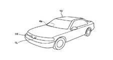
- the apparatus is mounted on a vehicle and is equipped with two infrared cameras 1R and 1L capable of detecting far infrared rays, and an image processing unit for detecting an object around the vehicle based on image data captured by the cameras 1R and 1L. 2, a speaker 3 that generates a warning by sound or voice based on the detection result, and an image obtained through imaging by the camera 1R or 1L are displayed, and the driver is made to recognize objects around the vehicle.
- a head-up display (hereinafter referred to as HUD) 4 is provided.
- the periphery monitoring device includes a yaw rate sensor 6 that detects the yaw rate of the vehicle, and a vehicle speed sensor 7 that detects the traveling speed (vehicle speed) of the vehicle, and the detection results of these sensors are sent to the image processing unit 2. It is done.
- the cameras 1 ⁇ / b> R and 1 ⁇ / b> L are arranged at positions symmetric with respect to the central axis passing through the center of the vehicle width at the front of the vehicle 10 so as to capture the front of the vehicle 10.
- the two cameras 1R and 1L are fixed to the vehicle so that their optical axes are parallel to each other and their height from the road surface is equal.
- the infrared cameras 1R and 1L have a characteristic that the level of the output signal becomes higher (that is, the luminance in the captured image becomes higher) as the temperature of the object is higher.
- the image processing unit 2 includes an A / D conversion circuit that converts an input analog signal into a digital signal, an image memory that stores a digitized image signal, a central processing unit (CPU) that performs various arithmetic processing, and a data RAM (Random Access Memory) used to store data, ROM (Read Only Memory) that stores programs executed by the CPU and data used (including tables and maps), driving signals for the speaker 3, display signals for the HUD 4, etc. Is provided.
- the output signals of the cameras 1R and 1L are converted into digital signals and input to the CPU.
- the HUD 4 is provided so that a screen 4 a is displayed at a front position of the driver on the front window of the vehicle 10. Thus, the driver can visually recognize the screen displayed on the HUD 4.
- a navigation device (not shown) that realizes various functions such as detecting the current position of a vehicle, calculating an optimum route to a destination, and displaying the current position and the optimum route together with map information
- the display device of the navigation device can be used.
- FIG. 3 is a flowchart showing a process executed by the image processing unit 2. The process is performed at predetermined time intervals.
- the output signals of the cameras 1R and 1L (that is, captured image data) are received as input, A / D converted, and stored in the image memory.
- the stored image data is a gray scale image including luminance information.
- step S14 the right image captured by the camera 1R is used as a reference image (alternatively, the left image may be used as a reference image), and the image signal is binarized. Specifically, a process of setting a region brighter than the luminance threshold value ITH to “1” (white) and a dark region to “0” (black) is performed. By this binarization processing, an object higher than a predetermined temperature, such as a living body, is extracted as a white region.
- the luminance threshold value ITH can be determined by any appropriate technique.
- step S15 the binarized image data is converted into run-length data.
- the coordinates of the start point (the leftmost pixel of each line) of the white area (referred to as a line) in each pixel row, and the start point to the end point (each The run length data is represented by the length (expressed by the number of pixels) up to the pixel on the right end of the line.
- the y-axis is taken in the vertical direction in the image
- the x-axis is taken in the horizontal direction.
- steps S16 and S17 the object is labeled and the object is extracted. That is, of the lines converted into run length data, a line having a portion overlapping in the y direction is regarded as one object, and a label is given thereto. Thus, one or a plurality of objects are extracted.
- step S21 it is determined whether each of the objects thus extracted is a pedestrian or an animal (typically a quadruped animal such as a deer or a bear, hereinafter simply referred to as an animal). If the extracted object is a pedestrian, the process proceeds to step S22. If the extracted object is an animal, the process proceeds to step S23.
- step S21 determines whether the extracted objects are pedestrians or animals (for example, if they are artificial structures). If all the extracted objects are not pedestrians or animals (for example, if they are artificial structures), the determination in step S21 is No. Proceeding to step S24, normal display is performed in which the grayscale image acquired in step S13 is output on the display device 4 without outputting an alarm.
- the process of determining whether the object is a pedestrian or an animal can be realized by any appropriate technique. For example, using known pattern matching, the similarity between the object extracted as described above and a predetermined pattern representing a pedestrian is calculated, and if the similarity is high, the object is determined to be a pedestrian. be able to. An animal can be similarly determined.
- processing for determining whether or not a person is a pedestrian is described in, for example, Japanese Patent Application Laid-Open No. 2007-241740, Japanese Patent Application Laid-Open No. 2007-334751, and the like.
- the process for determining whether or not an animal is described in, for example, Japanese Patent Application Laid-Open Nos. 2007-310705 and 2007-310706. *
- step S22 it is determined whether or not the object determined as a pedestrian is located within a predetermined alarm range from the vehicle.
- the object determined as an animal is located in the alarm range. Determine whether or not.
- an example of the predetermined alarm range is shown in FIG.
- the area AR0 indicates an imaging range that is an area that can be imaged by the cameras 1R and 1L.
- the processing in steps S11 to S17 in FIG. 3 is performed on the captured image corresponding to the imaging range AR0.
- the area AR1 corresponds to an area corresponding to a range obtained by adding a margin ⁇ (for example, about 50 to 100 cm) on both sides of the vehicle width ⁇ of the vehicle 10, in other words, the central axis of the vehicle 10 in the vehicle width direction. It is an area having a width of ( ⁇ / 2 + ⁇ ) on both sides, and is an approach determination area with a high possibility of collision if the object continues to exist as it is.
- the areas AR2 and AR3 are areas where the absolute value of the X coordinate is larger than the approach determination area (outside in the lateral direction of the approach determination area), and an intrusion determination that may cause an object in this area to enter the access determination area It is an area.
- Z1 that defines the size of regions AR1 to AR3 in the distance direction can be set to a predetermined value, for example.
- the determination in steps S22 and S23 is performed with the approach determination area AR1 as the alarm range.
- the object is a pedestrian
- the foot part of the pedestrian that is, at least a part of the bottom of the object on the image is included in the alarm range, the object Is determined to be within the alarm range.
- animals The same applies to animals.
- the position of the center of gravity of the object may be obtained, and if the position of the center of gravity is included in the alarm range, it may be determined that the object is located in the alarm range.
- step S22 If it is determined in step S22 that at least one pedestrian is located within the warning range (Yes in S22), a grayscale image is displayed on the display device 4 in step S25, and within the warning range in the image. A warning is output for the pedestrian located at. Specifically, alarm output is realized by performing individual highlighting on the position of each pedestrian in the grayscale image.
- the form in which the position of each object is individually highlighted is referred to as a first form.
- step S22 if there is no pedestrian determined to be located in the alarm range (No in S22), it indicates that there is no object to be noted in the alarm range. Therefore, alarm output is prohibited in step S26, and normal display is performed as in step S24.
- step S23 determines whether at least one animal is located within the alarm range (S23 is Yes)
- a grayscale image is displayed on the display device 4 in step S27, and the alarm in the image is displayed.
- Alarm output is performed for the animal located within the range. Specifically, warning output is realized by performing one highlight display on the entire displayed gray scale image.
- a form in which one highlighted display is performed on the entire displayed image is referred to as a second form.
- step S23 if there is no animal determined to be located within the alarm range (S23 is No), it is determined in step S30 whether or not a predetermined time has passed since the animal has left the alarm range. . If the predetermined time has not passed (No in S30), alarm output is continued in step S27. That is, the gray scale image acquired this time is displayed on the display device 4 and one highlight is displayed on the entire image. If the predetermined time has elapsed (S30 is Yes), alarm output is prohibited in step S31. In this case, the normal display is performed as in step S24.
- the determination as to whether a predetermined time has elapsed since the animal has left the alarm range can be realized by, for example, tracking an object determined to be the animal. For example, by tracking the animal, the timer is started when the animal goes out of the alarm range (for example, when it was within the alarm range in the previous process and outside the alarm range in the current process) Then, the elapsed time after the animal leaves the alarm range is timed. By referring to the timer, it can be determined whether or not the predetermined time has elapsed.
- the tracking method is described in, for example, Japanese Patent Laid-Open No. 2001-6096.
- the alarm output is continued for a predetermined time from the time of the departure. After a predetermined time has elapsed, the alarm output is cancelled.
- step S21 of the process of FIG. 3 it may be determined that both the pedestrian and the animal are included in the extracted object and both are located within the alarm range.
- an alarm combining the first form and the second form can be performed along with the display of the grayscale image on the display device 4. That is, for pedestrians, individual highlighting is performed as long as it is within the warning range, and for animals, it is displayed while it is within the warning range and for a predetermined time after leaving the warning range. One highlighting is performed on the entire image.
- FIG. 5 shows a schematic example of the temporal transition of the screen displayed on the display device 4 in the case of a pedestrian and an animal according to the process of FIG.
- An area surrounded by the line 101 and the line 102 indicates an alarm range.
- the actual grayscale image displayed on the display device 4 is displayed with a higher brightness (that is, white) than the background, but is easy to understand on the figure. Therefore, it should be noted that it is drawn so as not to follow such an actual display mode (thus, in the figure, pedestrians and animals are drawn blacker than the background). The same applies to the following drawings.
- warning output according to the first mode is performed. That is, in the display image, each of the pedestrians 111 to 113 positioned within the warning range is highlighted and surrounded by a frame.
- alarm output according to the second mode is performed in response to the determination that the animal 115 is within the alarm range at time t1 in (d). That is, in this embodiment, one icon image as indicated by reference numeral 121 is superimposed and displayed on the display image.
- the icon image 121 is one highlight that is made on the entire display image described above, and here, the icon image 121 indicates that a plurality of animals may exist in the vicinity.
- the icon image 121 is preferably displayed so as to draw the driver's attention. For example, a triangle can be displayed in red, and the icon image can be lit or blinked.
- the animal 115 has left the alarm range, but the predetermined time has not elapsed. Therefore, the alarm output according to the second form is continued. That is, the overall highlight display by the icon image 121 is continuously performed.
- the animal 115 is not displayed on the display device 4 because it is out of the imaging range (area AR0 in FIG. 4).
- the warning output according to the second mode that is, the overall highlight display by the icon image 121 is continuously performed. In this way, even if an animal is not only in the alarm range but out of the imaging range, until the predetermined time has elapsed, the animal and other animals that follow may be lurking around the vehicle. Will continue. As a result, the driver can be made aware of the potential danger.
- a display image as shown in FIG. 6 is generated.
- the difference from FIG. 5 is that highlighting with a frame is performed as long as the animal 115 exists within the imaging range.
- the form of alarm output by display has been described, but the alarm sound can also be switched between individual alarms and overall alarms.
- alarm output according to the first mode is performed in step S25
- alarm output by sound or voice is performed for each object together with the alarm output. Therefore, when there are a plurality of objects within the alarm range, an alarm using sound or voice is performed as many times as the number of objects.
- the alarm output according to the second mode is performed in step S27
- the alarm output is performed with one sound or sound for all the target object (s) together with the alarm output. Note that the type and content may be different between the alarm sound performed in the first form and the alarm sound performed in the second form.
- FIG. 7 is a flowchart showing a process executed by the image processing unit 2 according to another embodiment of the present invention. The process is performed at predetermined time intervals. Only differences from FIG. 3 will be described.
- step S41 it is determined whether the number of pedestrians determined to be within the warning range is greater than a predetermined number (for example, 1). If it is not more than the predetermined number (that is, if it is equal to or less than the predetermined number), the determination in step S41 is No. Proceeding to step S25, as described above, display according to the first mode, that is, individual highlighting is performed on the position of each pedestrian. If it is greater than the predetermined number, the determination in step S41 is Yes. Proceeding to step S42, the display according to the second mode, that is, one highlighted display is performed on the entire display image. The highlighting here may be different from the highlighting performed on the animal in step S27.
- a predetermined number for example, 1). If it is not more than the predetermined number (that is, if it is equal to or less than the predetermined number), the determination in step S41 is No. Proceeding to step S25, as described above, display according to the first mode, that is, individual highlighting is performed on the position of each pedestrian. If
- step S ⁇ b> 21 when both the pedestrian and the animal are included in the extracted object in step S ⁇ b> 21, steps S ⁇ b> 25 or S ⁇ b> 42 for the pedestrian. Can be combined with the alarm output of step S27 for animals.
- the warning output mode is switched between the first mode with individual highlighting and the second mode with overall highlighting.
- step S25 it is possible to perform alarm output by one sound or voice for each object, and in step S42, perform alarm output by one sound or voice for all objects. Can do.
- the type and content of the alarm sound in step S42 can be different from the alarm sound in step S25.
- the type and content of the alarm sound in step S42 can be different from the alarm sound output in step S27 (alarm output in the second mode for animals).
- FIG. 8 shows a schematic example of the temporal transition of the screen displayed on the display device 4 in the case of each pedestrian and animal according to the process of FIG.
- An area surrounded by the line 101 and the line 102 indicates an alarm range.
- the indications (d) to (f) for animals are shown for comparison, but these are the same as those shown in FIG. Further, the predetermined number in step S41 is assumed to be 1.
- step S42 display according to the second form, that is, overall highlighting is performed.
- one icon image as indicated by reference numeral 123 is superimposed and displayed on the display image.
- the icon image 123 is one highlight that is made on the entire display image described above.
- the icon image 123 indicates that there are a plurality of pedestrians.
- the icon image 123 is preferably displayed so as to draw the driver's attention. For example, a triangle can be displayed in red, and the icon image can be lit or blinked.
- the driver can recognize whether there are a plurality of pedestrians or a notification about the danger of animals.
- the two pedestrians 111 and 112 have left the warning range, but the remaining one pedestrian 113 is located within the warning range. Since the number of pedestrians within the warning range is 1, the display according to the first form, that is, the individual emphasis display by the frame is performed on the pedestrian 113 in step S25.
- the alarm output is switched between the first form and the second form depending on whether or not there are more than a predetermined number.
- the alarm output is switched between the first form and the second form depending on whether or not there are more than a predetermined number.
- an animal even if it is a single animal, there is a possibility that other animals may lurk in the vicinity as described above. Therefore, it is handled as a plurality (a group), and alarm output is always performed in the second form. By doing so, it is possible to present an easy-to-understand display for pedestrians and allow the driver to recognize the danger of lurking for animals.
- the predetermined number is not limited to 1, but it is preferable to check in advance how many emphasis displays are made to feel that the screen is difficult to see, and is preferably set to a number smaller than the emphasis display number at which it is difficult to see.
- the 2nd form which performs one emphasis display with respect to the whole display image is implement
- the overall highlighting technique is not limited to this, and other forms may be used.
- FIG. 9 shows an example of overall highlighting in another form when the object is a pedestrian.
- the entire frame according to the second mode is emphasized by displaying the outer frame 131 so as to surround the outer edge of the displayed image.
- the outer frame 131 can be colored to attract the driver's attention (for example, red or yellow), and the outer frame 131 can be lit or blinked.
- the overall brightness of the captured image is lowered (for example, the brightness value of each pixel is lowered by a predetermined value), and the image is displayed in a form with low contrast.
- the icon image 123 is superimposed and displayed.
- only the icon image 123 is displayed without displaying the captured image.
- the icon images 123 of (b) and (c) can also be turned on or blinked. As shown in (b) and (c), it is possible to urge the driver to gaze at the front by making it difficult to see the entire captured image together with the display of the icon image 123.
- FIG. 9 can be similarly applied to the alarm output according to the second form for animals.
- the approach determination area AR1 (FIG. 4) is set as a predetermined alarm range from the vehicle, and an alarm is output depending on whether or not a predetermined object exists within the alarm range.
- an alarm is output not only for an object existing in the alarm range but also for an object that exists in the intrusion determination area AR2 or AR3 and is determined to possibly enter the access determination area. You may make it do. Further, it may be determined whether there is a possibility that the vehicle will collide with the object, and if there is a possibility of collision, an alarm may be output.
- the present invention can be applied to other cameras (for example, a visible camera).
Landscapes
- Engineering & Computer Science (AREA)
- Physics & Mathematics (AREA)
- General Physics & Mathematics (AREA)
- Theoretical Computer Science (AREA)
- Multimedia (AREA)
- Remote Sensing (AREA)
- Electromagnetism (AREA)
- Radar, Positioning & Navigation (AREA)
- Computer Vision & Pattern Recognition (AREA)
- Human Computer Interaction (AREA)
- Traffic Control Systems (AREA)
- Closed-Circuit Television Systems (AREA)
- Mechanical Engineering (AREA)
- Image Processing (AREA)
Abstract
Description
2 画像処理ユニット
3 スピーカ
4 HUD
Claims (2)
- 車両に搭載され、該車両の周辺を撮像する撮像手段と、
前記撮像手段により撮像された画像に基づいて、前記車両の周辺の対象物を検出する手段と、
前記検出された対象物が、歩行者または動物であるかを判定する手段と、
前記歩行者または動物と判定された対象物が、前記車両から所定範囲内に存在する場合に、該車両の運転者に対して警報を行う警報手段と、を備える車両の周辺監視装置であって、
前記検出された対象物が前記動物であると判定され、かつ前記所定範囲内に存在すると判定されたならば、前記警報手段は、該動物が該所定範囲外に脱した後でも所定時間にわたって前記警報を継続することを特徴とする、周辺監視装置。 - さらに、前記検出された対象物が前記歩行者であると判定され、該歩行者が前記所定範囲内に存在する場合、該存在する歩行者が単数か複数かを判断する手段を備え、
前記警報手段は、該歩行者が単数である場合と複数である場合とで異なる形態の警報を行い、前記検出された対象物が前記動物であると判定され、かつ前記所定範囲内に存在する場合には、該警報手段は、該存在する動物が単数か複数かにかかわらず同一形態の警報を行う、
請求項1に記載の周辺監視装置。
Priority Applications (4)
| Application Number | Priority Date | Filing Date | Title |
|---|---|---|---|
| EP11750332.6A EP2544162B1 (en) | 2010-03-01 | 2011-02-21 | Surrounding area monitoring device for vehicle |
| JP2012502993A JP5577398B2 (ja) | 2010-03-01 | 2011-02-21 | 車両の周辺監視装置 |
| US13/580,014 US9321399B2 (en) | 2010-03-01 | 2011-02-21 | Surrounding area monitoring device for vehicle |
| CN201180010526.2A CN102782740B (zh) | 2010-03-01 | 2011-02-21 | 车辆周围监测装置 |
Applications Claiming Priority (2)
| Application Number | Priority Date | Filing Date | Title |
|---|---|---|---|
| JP2010044475 | 2010-03-01 | ||
| JP2010-044475 | 2010-03-01 |
Publications (1)
| Publication Number | Publication Date |
|---|---|
| WO2011108218A1 true WO2011108218A1 (ja) | 2011-09-09 |
Family
ID=44541888
Family Applications (1)
| Application Number | Title | Priority Date | Filing Date |
|---|---|---|---|
| PCT/JP2011/000949 WO2011108218A1 (ja) | 2010-03-01 | 2011-02-21 | 車両の周辺監視装置 |
Country Status (5)
| Country | Link |
|---|---|
| US (1) | US9321399B2 (ja) |
| EP (1) | EP2544162B1 (ja) |
| JP (1) | JP5577398B2 (ja) |
| CN (1) | CN102782740B (ja) |
| WO (1) | WO2011108218A1 (ja) |
Cited By (12)
| Publication number | Priority date | Publication date | Assignee | Title |
|---|---|---|---|---|
| JP2013088894A (ja) * | 2011-10-14 | 2013-05-13 | Honda Motor Co Ltd | 車両の運転支援装置 |
| JP2013092992A (ja) * | 2011-10-27 | 2013-05-16 | Honda Motor Co Ltd | 車両周辺監視装置 |
| JP2013120551A (ja) * | 2011-12-08 | 2013-06-17 | Denso It Laboratory Inc | 車両用運転支援装置 |
| JP2014006821A (ja) * | 2012-06-26 | 2014-01-16 | Honda Motor Co Ltd | 車両周辺監視装置 |
| JP2016024602A (ja) * | 2014-07-18 | 2016-02-08 | 日立オートモティブシステムズ株式会社 | 物体検知装置及びそれを用いた車両制御システム |
| JP2017004106A (ja) * | 2015-06-05 | 2017-01-05 | トヨタ自動車株式会社 | 車両の衝突回避支援装置 |
| CN106553655A (zh) * | 2016-12-02 | 2017-04-05 | 深圳地平线机器人科技有限公司 | 危险车辆检测方法和系统以及包括该系统的车辆 |
| JP2017200808A (ja) * | 2016-05-06 | 2017-11-09 | トヨタ自動車株式会社 | 情報表示装置 |
| WO2018092919A1 (ja) * | 2016-11-21 | 2018-05-24 | 京セラ株式会社 | 画像処理装置、撮像装置、および表示システム |
| JP2018085582A (ja) * | 2016-11-21 | 2018-05-31 | 京セラ株式会社 | 画像処理装置、撮像装置、および表示システム |
| WO2019039201A1 (ja) * | 2017-08-23 | 2019-02-28 | 日本精機株式会社 | 車両用表示装置 |
| US11893812B2 (en) | 2021-06-04 | 2024-02-06 | Toyota Jidosha Kabushiki Kaisha | Vehicle display device, vehicle display system, vehicle display method, and non-transitory storage medium stored with program |
Families Citing this family (27)
| Publication number | Priority date | Publication date | Assignee | Title |
|---|---|---|---|---|
| CN102782741B (zh) * | 2010-03-03 | 2015-08-19 | 本田技研工业株式会社 | 车辆周围监测装置 |
| JP5459154B2 (ja) * | 2010-09-15 | 2014-04-02 | トヨタ自動車株式会社 | 車両用周囲画像表示装置及び方法 |
| JP5991647B2 (ja) * | 2013-03-28 | 2016-09-14 | 株式会社デンソー | 車両用周辺監視制御装置 |
| JP6232759B2 (ja) * | 2013-06-07 | 2017-11-22 | ソニー株式会社 | 情報処理装置、接近対象物通知方法及びプログラム |
| JP6051307B2 (ja) * | 2013-07-05 | 2016-12-27 | クラリオン株式会社 | 運転支援装置 |
| JP5842110B2 (ja) * | 2013-10-10 | 2016-01-13 | パナソニックIpマネジメント株式会社 | 表示制御装置、表示制御プログラム、および記録媒体 |
| GB2521415B (en) | 2013-12-19 | 2020-03-04 | Here Global Bv | An apparatus, method and computer program for controlling a vehicle |
| JP6440115B2 (ja) | 2014-03-06 | 2018-12-19 | パナソニックIpマネジメント株式会社 | 表示制御装置、表示制御方法、および表示制御プログラム |
| KR102287373B1 (ko) | 2014-10-20 | 2021-08-05 | 한화테크윈 주식회사 | 경보 발생 장치 및 방법 |
| KR102383425B1 (ko) * | 2014-12-01 | 2022-04-07 | 현대자동차주식회사 | 전자 장치, 전자 장치의 제어 방법, 컴퓨터 프로그램 및 컴퓨터 판독 가능한 기록 매체 |
| JP6398675B2 (ja) * | 2014-12-09 | 2018-10-03 | 株式会社デンソー | 画像生成装置 |
| WO2016092650A1 (ja) * | 2014-12-10 | 2016-06-16 | 三菱電機株式会社 | 画像処理装置及び車載表示システム及び表示装置及び画像処理方法及び画像処理プログラム |
| DE102015002923B4 (de) | 2015-03-06 | 2023-01-12 | Mekra Lang Gmbh & Co. Kg | Anzeigeeinrichtung für ein Fahrzeug insbesondere Nutzfahrzeug |
| US9718405B1 (en) | 2015-03-23 | 2017-08-01 | Rosco, Inc. | Collision avoidance and/or pedestrian detection system |
| GB2538572B (en) * | 2015-05-18 | 2018-12-19 | Mobileye Vision Technologies Ltd | Safety system for a vehicle to detect and warn of a potential collision |
| US10093181B1 (en) | 2015-09-30 | 2018-10-09 | Waymo Llc | Occupant facing vehicle display |
| DE102015118977A1 (de) * | 2015-11-05 | 2017-05-11 | Connaught Electronics Ltd. | Erfassungsvorrichtung für ein Kraftfahrzeug, Fahrerassistenzsystem sowie Kraftfahrzeug |
| JP6805716B2 (ja) * | 2016-01-25 | 2020-12-23 | 株式会社Jvcケンウッド | 表示装置、表示方法、プログラム |
| EP3293717B1 (en) | 2016-09-08 | 2021-11-10 | KNORR-BREMSE Systeme für Nutzfahrzeuge GmbH | An electronically controlled braking system |
| KR102581779B1 (ko) | 2016-10-11 | 2023-09-25 | 주식회사 에이치엘클레무브 | 교차로충돌방지시스템 및 교차로충돌방지방법 |
| CN107554472A (zh) * | 2017-08-23 | 2018-01-09 | 中国科学院自动化研究所 | 一种车辆碰撞警示系统和方法 |
| JP7006235B2 (ja) * | 2017-12-18 | 2022-01-24 | トヨタ自動車株式会社 | 表示制御装置、表示制御方法および車両 |
| JP7077616B2 (ja) * | 2017-12-28 | 2022-05-31 | トヨタ自動車株式会社 | 表示制御装置および表示制御方法 |
| JP7211674B2 (ja) * | 2018-09-27 | 2023-01-24 | 株式会社Subaru | 移動体監視装置、並びにこれを用いる車両制御システムおよび交通システム |
| JP7113364B2 (ja) * | 2018-10-18 | 2022-08-05 | パナソニックIpマネジメント株式会社 | 撮像装置 |
| US20200342623A1 (en) * | 2019-04-23 | 2020-10-29 | Apple Inc. | Systems and methods for resolving hidden features in a field of view |
| CN110689760A (zh) * | 2019-09-26 | 2020-01-14 | 浙江海洋大学 | 一种山区内保护道路安全的系统及方法 |
Citations (8)
| Publication number | Priority date | Publication date | Assignee | Title |
|---|---|---|---|---|
| JP2001006096A (ja) | 1999-06-23 | 2001-01-12 | Honda Motor Co Ltd | 車両の周辺監視装置 |
| JP2007241740A (ja) | 2006-03-09 | 2007-09-20 | Honda Motor Co Ltd | 車両周辺監視装置 |
| JP2007310706A (ja) | 2006-05-19 | 2007-11-29 | Honda Motor Co Ltd | 車両周辺監視装置 |
| JP2007310705A (ja) | 2006-05-19 | 2007-11-29 | Honda Motor Co Ltd | 車両周辺監視装置 |
| JP2007334751A (ja) | 2006-06-16 | 2007-12-27 | Honda Motor Co Ltd | 車両周辺監視装置 |
| JP2008021035A (ja) * | 2006-07-11 | 2008-01-31 | Fujitsu Ten Ltd | 画像認識装置、画像認識方法および車両制御装置 |
| JP2008254710A (ja) * | 2007-04-09 | 2008-10-23 | Fujitsu Ten Ltd | 障害物検知装置 |
| JP4334686B2 (ja) | 1999-07-07 | 2009-09-30 | 本田技研工業株式会社 | 車両の画像表示装置 |
Family Cites Families (9)
| Publication number | Priority date | Publication date | Assignee | Title |
|---|---|---|---|---|
| KR0183299B1 (ko) * | 1996-11-04 | 1999-04-15 | 삼성전자주식회사 | 자동차의 주변사항을 알려주는 네비게이션 장치 및 그 제어방법 |
| US6535242B1 (en) * | 2000-10-24 | 2003-03-18 | Gary Steven Strumolo | System and method for acquiring and displaying vehicular information |
| CA2343493A1 (en) * | 2001-04-09 | 2002-10-09 | Harold Hykawy | Roadside animal warning system |
| DE102004009924A1 (de) | 2004-02-23 | 2005-09-01 | Valeo Schalter Und Sensoren Gmbh | Verfahren und Warnvorrichtung zum grafischen Aufbereiten eines Bildes einer Kamera |
| CN100429101C (zh) * | 2005-09-09 | 2008-10-29 | 中国科学院自动化研究所 | 汽车行驶安全监控系统及监控方法 |
| DE102006047777A1 (de) * | 2006-03-17 | 2007-09-20 | Daimlerchrysler Ag | Virtuelles Spotlight zur Kennzeichnung von interessierenden Objekten in Bilddaten |
| CN101201402A (zh) * | 2006-12-15 | 2008-06-18 | 上海通运汽车科技有限公司 | 一种汽车行驶中检测危险接近物体的方法和装置 |
| JP4470067B2 (ja) * | 2007-08-07 | 2010-06-02 | 本田技研工業株式会社 | 対象物種別判定装置、車両 |
| US20100020170A1 (en) | 2008-07-24 | 2010-01-28 | Higgins-Luthman Michael J | Vehicle Imaging System |
-
2011
- 2011-02-21 WO PCT/JP2011/000949 patent/WO2011108218A1/ja active Application Filing
- 2011-02-21 EP EP11750332.6A patent/EP2544162B1/en not_active Not-in-force
- 2011-02-21 US US13/580,014 patent/US9321399B2/en active Active
- 2011-02-21 JP JP2012502993A patent/JP5577398B2/ja not_active Expired - Fee Related
- 2011-02-21 CN CN201180010526.2A patent/CN102782740B/zh not_active Expired - Fee Related
Patent Citations (8)
| Publication number | Priority date | Publication date | Assignee | Title |
|---|---|---|---|---|
| JP2001006096A (ja) | 1999-06-23 | 2001-01-12 | Honda Motor Co Ltd | 車両の周辺監視装置 |
| JP4334686B2 (ja) | 1999-07-07 | 2009-09-30 | 本田技研工業株式会社 | 車両の画像表示装置 |
| JP2007241740A (ja) | 2006-03-09 | 2007-09-20 | Honda Motor Co Ltd | 車両周辺監視装置 |
| JP2007310706A (ja) | 2006-05-19 | 2007-11-29 | Honda Motor Co Ltd | 車両周辺監視装置 |
| JP2007310705A (ja) | 2006-05-19 | 2007-11-29 | Honda Motor Co Ltd | 車両周辺監視装置 |
| JP2007334751A (ja) | 2006-06-16 | 2007-12-27 | Honda Motor Co Ltd | 車両周辺監視装置 |
| JP2008021035A (ja) * | 2006-07-11 | 2008-01-31 | Fujitsu Ten Ltd | 画像認識装置、画像認識方法および車両制御装置 |
| JP2008254710A (ja) * | 2007-04-09 | 2008-10-23 | Fujitsu Ten Ltd | 障害物検知装置 |
Non-Patent Citations (1)
| Title |
|---|
| See also references of EP2544162A4 |
Cited By (13)
| Publication number | Priority date | Publication date | Assignee | Title |
|---|---|---|---|---|
| JP2013088894A (ja) * | 2011-10-14 | 2013-05-13 | Honda Motor Co Ltd | 車両の運転支援装置 |
| JP2013092992A (ja) * | 2011-10-27 | 2013-05-16 | Honda Motor Co Ltd | 車両周辺監視装置 |
| JP2013120551A (ja) * | 2011-12-08 | 2013-06-17 | Denso It Laboratory Inc | 車両用運転支援装置 |
| JP2014006821A (ja) * | 2012-06-26 | 2014-01-16 | Honda Motor Co Ltd | 車両周辺監視装置 |
| JP2016024602A (ja) * | 2014-07-18 | 2016-02-08 | 日立オートモティブシステムズ株式会社 | 物体検知装置及びそれを用いた車両制御システム |
| JP2017004106A (ja) * | 2015-06-05 | 2017-01-05 | トヨタ自動車株式会社 | 車両の衝突回避支援装置 |
| JP2017200808A (ja) * | 2016-05-06 | 2017-11-09 | トヨタ自動車株式会社 | 情報表示装置 |
| JP2018085582A (ja) * | 2016-11-21 | 2018-05-31 | 京セラ株式会社 | 画像処理装置、撮像装置、および表示システム |
| WO2018092919A1 (ja) * | 2016-11-21 | 2018-05-24 | 京セラ株式会社 | 画像処理装置、撮像装置、および表示システム |
| US11030468B2 (en) | 2016-11-21 | 2021-06-08 | Kyocera Corporation | Image processing apparatus |
| CN106553655A (zh) * | 2016-12-02 | 2017-04-05 | 深圳地平线机器人科技有限公司 | 危险车辆检测方法和系统以及包括该系统的车辆 |
| WO2019039201A1 (ja) * | 2017-08-23 | 2019-02-28 | 日本精機株式会社 | 車両用表示装置 |
| US11893812B2 (en) | 2021-06-04 | 2024-02-06 | Toyota Jidosha Kabushiki Kaisha | Vehicle display device, vehicle display system, vehicle display method, and non-transitory storage medium stored with program |
Also Published As
| Publication number | Publication date |
|---|---|
| JP5577398B2 (ja) | 2014-08-20 |
| US20120314074A1 (en) | 2012-12-13 |
| JPWO2011108218A1 (ja) | 2013-06-20 |
| EP2544162B1 (en) | 2015-04-29 |
| EP2544162A1 (en) | 2013-01-09 |
| EP2544162A4 (en) | 2014-01-22 |
| CN102782740A (zh) | 2012-11-14 |
| US9321399B2 (en) | 2016-04-26 |
| CN102782740B (zh) | 2015-04-15 |
Similar Documents
| Publication | Publication Date | Title |
|---|---|---|
| JP5577398B2 (ja) | 車両の周辺監視装置 | |
| JP5706874B2 (ja) | 車両の周辺監視装置 | |
| JP5503728B2 (ja) | 車両の周辺監視装置 | |
| JP5198346B2 (ja) | 車両周辺監視装置 | |
| JP4456086B2 (ja) | 車両周辺監視装置 | |
| JP4410292B1 (ja) | 車両の周辺監視装置 | |
| JP5689872B2 (ja) | 車両の周辺監視装置 | |
| JP5576937B2 (ja) | 車両の周辺監視装置 | |
| JP4528283B2 (ja) | 車両周辺監視装置 | |
| JP4988781B2 (ja) | 車両の周辺監視装置 | |
| JP5991647B2 (ja) | 車両用周辺監視制御装置 | |
| JP2010108264A (ja) | 車両周辺監視装置 | |
| JP4334686B2 (ja) | 車両の画像表示装置 | |
| JP5192007B2 (ja) | 車両の周辺監視装置 | |
| JP2011227657A (ja) | 車両の周辺を監視する装置 | |
| JP5345992B2 (ja) | 車両周辺監視装置 | |
| JP2009126493A (ja) | 障害物検出装置 | |
| JP6087240B2 (ja) | 車両周辺監視装置 | |
| JP2010191666A (ja) | 車両の周辺監視装置 | |
| JP5192009B2 (ja) | 車両の周辺監視装置 | |
| JP2010092437A (ja) | 車両の周辺監視装置 | |
| JP5885640B2 (ja) | 車両周辺監視装置 |
Legal Events
| Date | Code | Title | Description |
|---|---|---|---|
| WWE | Wipo information: entry into national phase |
Ref document number: 201180010526.2 Country of ref document: CN |
|
| 121 | Ep: the epo has been informed by wipo that ep was designated in this application |
Ref document number: 11750332 Country of ref document: EP Kind code of ref document: A1 |
|
| WWE | Wipo information: entry into national phase |
Ref document number: 2012502993 Country of ref document: JP |
|
| WWE | Wipo information: entry into national phase |
Ref document number: 2011750332 Country of ref document: EP |
|
| WWE | Wipo information: entry into national phase |
Ref document number: 13580014 Country of ref document: US |
|
| NENP | Non-entry into the national phase |
Ref country code: DE |