WO2011105346A1 - ステーブおよび高炉 - Google Patents
ステーブおよび高炉 Download PDFInfo
- Publication number
- WO2011105346A1 WO2011105346A1 PCT/JP2011/053772 JP2011053772W WO2011105346A1 WO 2011105346 A1 WO2011105346 A1 WO 2011105346A1 JP 2011053772 W JP2011053772 W JP 2011053772W WO 2011105346 A1 WO2011105346 A1 WO 2011105346A1
- Authority
- WO
- WIPO (PCT)
- Prior art keywords
- stave
- protrusion
- blast furnace
- shaft
- charge
- Prior art date
- Legal status (The legal status is an assumption and is not a legal conclusion. Google has not performed a legal analysis and makes no representation as to the accuracy of the status listed.)
- Ceased
Links
Images











Classifications
-
- C—CHEMISTRY; METALLURGY
- C21—METALLURGY OF IRON
- C21B—MANUFACTURE OF IRON OR STEEL
- C21B7/00—Blast furnaces
- C21B7/10—Cooling; Devices therefor
-
- F—MECHANICAL ENGINEERING; LIGHTING; HEATING; WEAPONS; BLASTING
- F27—FURNACES; KILNS; OVENS; RETORTS
- F27B—FURNACES, KILNS, OVENS OR RETORTS IN GENERAL; OPEN SINTERING OR LIKE APPARATUS
- F27B1/00—Shaft or like vertical or substantially vertical furnaces
- F27B1/10—Details, accessories or equipment specially adapted for furnaces of these types
- F27B1/24—Cooling arrangements
-
- F—MECHANICAL ENGINEERING; LIGHTING; HEATING; WEAPONS; BLASTING
- F27—FURNACES; KILNS; OVENS; RETORTS
- F27D—DETAILS OR ACCESSORIES OF FURNACES, KILNS, OVENS OR RETORTS, IN SO FAR AS THEY ARE OF KINDS OCCURRING IN MORE THAN ONE KIND OF FURNACE
- F27D1/00—Casings; Linings; Walls; Roofs
- F27D1/12—Casings; Linings; Walls; Roofs incorporating cooling arrangements
Definitions
- a structure is often used in which a stave is installed inside the iron skin and a refractory brick is installed inside.
- the inner surface of the blast furnace is subjected to mechanical wear by being exposed to the charge descending in the furnace while receiving high heat in the furnace. Then, after a certain period of time has passed and the refractory bricks are worn, the surface of the stave is worn.
- a structure has been developed in which a recess is formed on the surface of the stave inside the furnace, and a refractory is fitted in the recess (see Patent Document 1).
- the charge is layered granular coke and iron ore (sintered, lump ore, etc.), and the stave in this part is charged particles.
- the above-mentioned fitted refractory cannot be said to have sufficient durability.
- the object of the present invention is to provide a stave and a blast furnace capable of obtaining sufficient durability against mechanical wear caused by charged particles.
- the present invention is based on the knowledge obtained as a result of diligent research by the present inventors, that is, mechanical wear due to the particles of the charge depends on the shape and hardness of the charge particles and the descending speed. It is based on the knowledge that wear can be remarkably reduced by suppressing the speed of the charge on the surface of the steel (forming a stagnant layer).
- the present invention suppresses the speed of the charge on the surface of the stave based on the aforementioned knowledge.
- As a structure for forming the stagnant layer protrusions were formed on the surface of the stave inside the blast furnace to make it easy to generate a stagnant layer of charge covering the surface of the stave.
- the specific configuration is as follows.
- a stave according to an aspect of the present invention is a stave provided on the inner periphery of a shaft portion of a blast furnace, and a stave body having a reference surface facing the internal space of the blast furnace; A plurality of protrusions protruding toward the inside of the blast furnace.
- the inner surface of the blast furnace is constituted by the reference surface of the stave body, and the charge descending in the furnace is decelerated by the protrusion protruding from the reference surface to the inside of the furnace.
- a stagnant layer is formed along the reference plane.
- the stagnant layer has a lower relative speed with respect to the reference surface of the stave body, reducing mechanical wear of the reference surface of the stave body due to the particles of the charge, resulting in a granular charge that descends the shaft part of the blast furnace. Also, sufficient durability can be obtained.
- the protruding dimension of the protrusion is 50 to 150 mm; and the interval between the adjacent protrusions is 200 to 700 mm.
- the protrusions projection dimensions: 50 to 150 mm, intervals: 200 to 700 mm
- the charge is decelerated, and in particular, part of the charge is The movement is stopped by the protrusion, and a stagnant layer is formed.
- the plane is covered with the stagnant layer, so that the deceleration effect on the charge is enhanced.
- a general charge that is, an ore-type charge having a particle size of about 8 to 25 mm and a coke-type charge having a particle size of about 20 to 55 mm are alternately charged.
- a stagnant layer is likely to be formed along the reference plane of the stave body.
- tip can be suppressed, and the wear mitigation effect of the whole stave can be exhibited.
- the distance is smaller than 200 mm, the recess formed by the adjacent protrusions along the reference surface of the stave body becomes ineffective, and the charge is not easily caught.
- the interval is larger than 700 mm, the interval between the stagnant layers opens, and the covering effect does not sufficiently appear.
- the said projection part As for the stave as described in said (1), it is desirable for the said projection part to be provided continuously or intermittently along the circumferential direction of the said blast furnace. According to the stave described in the above (3), it is easy to properly maintain the circumferential balance in the furnace by the projections continuous in the entire circumference in the furnace circumferential direction, and to maintain a good operational record. Can do.
- the protrusion part may be arrange
- the stave as described in said (1) it is desirable for the surface of the said projection part to be formed with a high-hardness material. According to the stave described in (4) above, it is possible to prevent the protrusions themselves from being worn.
- the reference surface of the stave body is reduced in wear by formation of a stagnant layer (cell flying) guided by the protrusion, but the protrusion itself is exposed from the stagnant layer to the inside of the furnace. In some cases, wear from particles of the undecelerated charge may continue to occur.
- the stave described in the above (4) has a recess formed in the stave body;
- the protrusion is a block embedded in the recess and protruding from the reference surface;
- the block is preferably made of a high hardness material.
- the protrusion is provided in the recess formed in the stave body, that is, the stave body and the protrusion are separate, and therefore the material of the stave body is different.
- the protrusion of the high hardness material can be easily formed.
- (6) in the stave described in the above (4) it is preferable that the protrusion is formed integrally with the stave body.
- the stave described in (6) above it is possible to easily implement the surface of the protruding portion made of the above-described high-hardness material, and because the protruding portion is formed integrally with the stave body, it is easy to manufacture. .
- cooling pipes are also passed through the protrusions, it is very useful in processing that the protrusions and the stave body are integrated.
- the stave main body is copper or a copper alloy.
- the cooling efficiency as a stave used for a shaft part can be improved.
- the stave layer according to one embodiment of the present invention can alleviate the wear of the stave body, although it is susceptible to wear due to charged particles. Furthermore, high cooling performance can be maintained over a long period of time.
- a pipe line for cooling the protrusion is provided inside the protrusion.
- the stave described in the above (8) in addition to the normal cooling conduit provided in the stave body, it can be directly cooled by the conduit that cools the protrusion, so the surface hardness of the protrusion can be reduced. It can be maintained high, and the anti-wear effect can be maintained over a long period of time.
- the stave described in the above (1) is an angle formed by a side surface on the lower side of the projecting portion and a reference surface among two opposing side surfaces of the projecting portion provided on both ends of the reference surface. Is preferably less than 90 degrees. According to the stave described in (9) above, since the angle formed between the side surface on the lower side of the protrusion and the reference surface is less than 90 degrees, the charged object can be easily supported by the inclined protrusion. Thereby, since it can suppress further that a charging material falls below, sufficient durability is obtained also with respect to mechanical abrasion.
- a blast furnace according to an aspect of the present invention includes the stave according to any one of (1) to (9).
- the stave according to one aspect of the present invention be installed in a portion where the charged material falls in a granular state in the shaft portion of the blast furnace and its periphery.
- a stagnant layer is formed by the protrusions of the stave, and wear on the reference surface of the stave body is reduced.
- a blast furnace 1 has a cylindrical furnace body 2 constructed on a foundation ground.
- the furnace body 2 has a cylindrical shape, and is sequentially divided into an upper gas collecting mantel 3 into a furnace mouth part S1, a shaft part S2, a furnace belly part S3, a morning glory part S4, a tuyere part S5, and a furnace bottom part S6.
- the inner diameter of the shaft portion S2 expands downward
- the inner diameter of the furnace belly portion S3 is the maximum diameter
- the inner diameter of the morning glory portion S4 decreases downward.
- a charging device is usually installed in the gas collection mantel 3, and a granular charge 4 is charged into the blast furnace 1 from this charging device.
- a charge 4 an ore-based charge having a particle size of about 8 to 25 mm and a coke-based charge having a particle size of about 20 to 55 mm are alternately charged.
- a massive band 4A in which iron ore and coke are alternately layered is formed in the furnace port portion S1 and the shaft portion S2 in the furnace.
- the furnace body 2 is provided with a tuyere 5 above the furnace bottom S6, and hot air 5A is blown from here.
- the hot air 5A gradually raises the temperature of the coke in the block 4A as it descends in the furnace, and in the vicinity of the tuyere 5, raceway 5B (high-speed gas is blown from the tuyere 5 into the tuyere 5 A space with a high porosity in which the coke is fluidized is formed. Due to the high heat of the raceway 5B, the iron ore in the block 4A is melted.
- a substantially conical fusion band 4B is formed in the blast furnace 1 from the morning glory part S4 to the lower part of the shaft part S2. .
- the iron 6A melted in the fusion zone 4B passes through the dripping zone 4C, drops toward the furnace bottom S6, and accumulates in the furnace bottom S6 as a molten iron 6B.
- Coke or the like descends after passing through the dripping zone 4C, accumulates in the furnace bottom S6, and forms a conical furnace core 4D on the hot metal 6B.
- a hot iron outlet 6 is installed in the furnace bottom portion S ⁇ b> 6, and the hot metal 6 ⁇ / b> B accumulated in the furnace bottom portion S ⁇ b> 6 is taken out of the blast furnace 1 through the hot iron outlet 6.
- the furnace body 2 has an iron skin 2A on the outermost periphery, and a cooling stave and a refractory brick 2D are affixed inside the iron skin 2A.
- a stave 2B for the shaft is stretched in a region S7 facing from the upper portion of the shaft portion S2 to the middle lump 4A. In this region S7, since the granular charge 4 contained in the massive band 4A descends sequentially while contacting the surface of the stave 2B, mechanical wear may occur on the surface of the stave 2B.
- the morning glory part and the furnace belly stave 2C are attached to the inner periphery of the region S8 including the furnace belly S3 and the morning glory part S4 from the lower part of the shaft part S2.
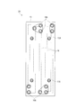
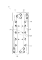
- the shaft stave 10 shown in FIG. 2 is adopted as the shaft stave 2B shown in FIG. 2, 3, 4 ⁇ / b> A, 4 ⁇ / b> B, and 5, the shaft stave 10 includes a stave body 11 having a reference surface R facing the internal space of the blast furnace 1, and a blast furnace 1 than the reference surface R. And a plurality of projecting portions 12 projecting inward.
- the protrusion 12 is formed integrally with the stave body 11.
- the stave body 11 is in the form of a thin plate cut out from a copper or copper alloy plate.
- the shaft stave 10 may be made of a cast or cast iron made of copper or a copper alloy. As shown in FIG. 2 and FIG.
- the protrusions 12 are formed in a plurality of rows on the surface side of the stave body 11 so as to be horizontally continuous. As shown in FIG. 2, a lower plane 13 is formed between the plurality of protrusions 12.
- One groove 21 is formed in the flat surface 13, and a refractory brick 15 is fitted into the groove 21. Further, a refractory castable may be used in place of the refractory brick 15. Further, the number and location of the grooves 21 are not limited to this.
- FIG. 4A is a diagram in which the groove 21 is omitted.
- the flat surface 13 is formed by cutting from the surface of the stave body 11, and the protrusion 12 is formed by being left uncut during the cutting.
- the flat surface 13 is the reference surface R of the shaft stave 10, and the protrusion 12 protrudes from the reference surface R of the shaft stave 10.
- the protrusions 12 are continuously provided along the circumferential direction of the blast furnace 1 as shown in FIG. 4A.
- the part 12 forms a complete annular shape.
- the protrusion part 12 may be arrange
- various geometric patterns such as a lattice shape and a zigzag shape can be adopted, but it is always preferable to adopt a point-symmetric arrangement considering the circumferential balance.
- FIG. 4B is a view in which the groove 21 is omitted.
- the angle ⁇ between the lower surface of the protrusion 12, that is, the side surface 12a and the reference surface R is 90 degrees. Is less than.
- the side surface 12a is horizontal with respect to the ground of the installation location.
- a bolt receiving portion 11 ⁇ / b> A for mounting on the blast furnace 1 is formed on the back side of the stave body 11.
- cooling pipe connection ports 16 ⁇ / b> A and 17 ⁇ / b> A are formed on the back side of the stave body 11, and cooling pipes 16 and 17 are formed inside the stave body 11.
- the pipe line 16 is disposed along the flat surface 13, and the flat surface 13 that is the reference surface R of the shaft stave 10 can be cooled by the cooling water supplied from the connection port 16 ⁇ / b> A.
- a pipe line 17 for cooling the protrusion 12 is provided inside the protrusion 12. With this configuration, the protrusion 12 can be cooled by the cooling water supplied from the connection port 17A.
- the tip surface of the protrusion 12 is coated with a high-hardness material such as TiN, TiC, WC, or Ti—Al—N.
- the protruding portion 12 of the shaft stave 10 has a protrusion amount (protrusion dimension) E from the reference surface R of 50 to 150 mm (approximately 50 mm of the maximum particle size of the coke-based charge having a large average particle size). 1 to 3 times), the thickness T in the height direction is 50 to 150 mm, and the distance D (corresponding to the height direction dimension of the flat surface 13) between other adjacent protrusions 12 is 200 to 700 mm, preferably 250-350 mm (50 mm before and after 300 mm).
- FIG. 6 schematically shows a state during operation of the shaft stave 10 according to the present embodiment (projection amount E of protrusions: 50 to 150 mm, interval D: 200 to 700 mm).
- the enlarged shape of the shaft stave 10 of the present embodiment is schematically shown in the upper part of the paper surface of FIG. Further, in the lower part of the page of FIG. 6, graphs of the descending speeds V1 and V2 at the transverse position P1 and the transverse position P2 in the upper part of FIG. 6 are shown.
- FIG. 6 schematically shows a state during operation of the shaft stave 10 according to the present embodiment (projection amount E of protrusions: 50 to 150 mm, interval D: 200 to 700 mm).
- the enlarged shape of the shaft stave 10 of the present embodiment is schematically shown in the upper part of the paper surface of FIG. Further, in the lower part of the page of FIG. 6, graphs of the descending speeds V1 and V2 at the transverse position P1 and the transverse position P2 in the upper part of
- FIG. 7 shows a case where the distance D between the protrusions 12 is extremely large (the distance D between the protrusions 12> 700 mm).
- the enlarged shape of the shaft stave 10 is schematically shown in the upper part of the drawing of FIG. Further, in the lower part of the page of FIG. 7, graphs of the descending speeds V3 and V4 at the transverse position P3 and the transverse position P4 in the upper part of FIG. 7 are shown.
- FIG. 8 shows a case where the distance D between the protrusions 12 is small (the distance D ⁇ 200 mm between the protrusions).
- the enlarged shape of the shaft stave 10 is schematically shown in the upper part of the paper surface of FIG. Further, a graph of the lowering speed V5 at the transverse position P5 in the upper part of FIG.
- the charge 4 descends inside the blast furnace 1 (see FIG. 1) during operation.
- the charge 4 in the blast furnace 1 descends at a substantially constant speed.
- the charge 4 is decelerated due to friction with the shaft stave 10. Accordingly, a low speed region is generated between the stave 10 and the boundary B in the charge 4 in the vicinity of the shaft stave 10.
- the descending speed of the charge 4 is substantially constant (average descending speed V0) inside the furnace from the boundary B, but the descending speed gradually decreases from the boundary B to the reference plane R of the stave 10.
- the change in the descending speed at this time greatly varies depending on the shape of the reference surface R of the shaft stave 10, that is, the installation state of the protrusion 12.
- the protrusion 12 (projection amount E: 50 to 150 mm, interval D: 200 to 700 mm) according to the present embodiment is formed, from the boundary B to the reference plane R of the shaft stave 10 In this region, the charge 4 decelerates, and in particular, a part of the charge 4 is stopped by the protrusion 12 to form the stagnant layers 19 and 18.
- the stagnant layers 19 and 18 are formed on the upper surface side of the protruding portion 12 of the shaft stave 10 and grow upward along the flat surface 13 as a reference surface. Most of the movement of the stagnation layer 19 on the back side is stopped, and the stagnation layer 18 inside the blast furnace 1 is gradually replaced, and the descending speed of the stagnation layer 18 is very slow. As a result of the stagnation layers 19 and 18 being formed, the flat surface 13 is covered with the stagnation layers 19 and 18, so that the deceleration effect on the charge 4 is enhanced.
- the average descending speed V01 is substantially constant inside the blast furnace 1.
- the boundary B is a position at a distance B1 from the reference plane R of the shaft stave 10.
- the descending speed V1 decreases from the boundary B to the reference plane R, and becomes the descending speed VW1 on the reference plane R.
- the descending speed VW1 is very slow due to the formation of the stagnant layers 19 and 18, so that the wear of the shaft stave 10 on the stave body 11 is suppressed.
- the average descending speed V02 inside the blast furnace 1 is the same as the average descending speed V01 at the transverse position P1, and the descending speed is from the boundary B to the reference plane R of the shaft stave 10. Decrease.
- the descending speed V2 and the descending speed V1 are the same.
- the tip surface R1 of the protrusion 12 has a descending speed VL2.
- the distance from the reference surface R to the tip surface R1 corresponds to the protrusion dimension E of the protrusion 12.
- the descending speed VL2 is the same as the descending speed VL1 at the position corresponding to the front end surface R1 at the crossing position P1.
- the descending speed VL1 at the tip end surface R1 has a large internal friction between the charge 4 of the stagnant layers 19 and 18 formed by the protrusion 12 and the boundary portion of the charge 4 that descends.
- the descent speed becomes slower.
- the descending speed VL2 is affected by the descending speed VL1, and becomes the same descending speed as the descending speed VL1.
- the boundary B is a position at a distance B3 from the reference plane R of the shaft stave 10. There is a deceleration of the charge 4 in the region from the boundary B to the reference plane R.
- the stagnant layers 19 and 18 formed by the protrusion 12 as shown in FIG. 6 are not formed over the entire range of the height W of the recess, but are formed only at the lower end portion of the height W.
- the average descending speed V03 inside the blast furnace 1 is the same as the average descending speed V01 at the transverse position P1, and the descending speed is from the boundary B to the reference plane R of the shaft stave 10. Decrease. At this time, the descending speed decreases like the descending speed V1, but since the distance D between the protrusions 12 is extremely large, the influence of the stagnant layers 19 and 18 on the plane 13 is small, and the descending speed of the plane 13 is equal to that of the plane 13. It becomes the frictional force of the container 4. As a result, when the distance D between the protrusions 12 of the shaft stave 10 is very large, the descending speed is not significantly reduced.
- the average descending speed V04 inside the blast furnace 1 is the same as the average descending speed V03 at the transverse position P3, and the descending speed is from the boundary B to the reference plane R of the shaft stave 10. Decrease. At this time, the lowering speed decreases like the lowering speed V3, but at the tip end surface R1 of the protrusion 12, the lowering speed VL4 is reached. Here, the distance from the reference surface R to the tip surface R1 corresponds to the protrusion dimension E of the protrusion 12. The descending speed VL4 is faster than the descending speed VL3 at the distal end surface R1 at the relative position at the transverse position P3.
- the cross section at the crossing position P4 is smaller in the cross section from the boundary B of the crossing position P3 to the reference plane R and the cross section from the boundary B to the front end face R1 of the crossing position P4. That is, since the distance from the boundary B of the crossing position P4 to the tip surface R1 is shorter than the distance from the boundary B of the crossing position P3 to the reference plane R, when the same charge 4 passes, the descending speed VL3 Compared to the lowering speed VL4, the lowering speed becomes faster.
- the lowering speed VW3 at the reference surface R is significantly higher than the lowering speed VW1, and the wear on the flat surface 13 which is the reference surface of the stave body is significantly increased compared to the state of FIG. .
- the wear on the flat surface 13 which is the reference surface of the stave body 11 is greatly increased.
- the boundary B is a position at a distance B5 from the reference plane R of the shaft stave 10, and from the boundary B to the stave In the region up to the reference plane R of the main body, the speed of the charge 4 is reduced.
- a flat surface is formed at the tip end surface R1 of the protrusion 12, the friction force between the charge 4 and the flat surface is generated, and the deceleration effect described with reference to FIG. 6 cannot be obtained.
- the descending speed V5 at the crossing position P5 it is the average descending speed V05 inside the blast furnace 1, and the descending speed V5 decreases from the boundary B to the reference surface R of the stave body 11, but at the tip end surface R1 of the protrusion 12.
- the descending speed of the charge 4 that contacts the shaft stave 10 varies depending on the arrangement of the protrusions 12, that is, the interval between the adjacent protrusions 12.
- an appropriate range of the interval D of the protrusions 12 will be described based on a test result of a tenth model of the shaft stave 10 of the present embodiment.
- FIG. 9 shows that the distance D between the protrusions 12 of the shaft stave 10 is changed from 0 to 120 mm in the configuration shown in FIG. It is the graph which measured the speed
- FIG. 10 is a graph obtained by measuring the descending speed VL (that is, the speed of the charge 4 contacting the tip of the protrusion 12) at the tip surface R1 in the configuration of FIG. 6 described above.
- the thickness T of the protruding portion 12 of the shaft stave 10 was 5 mm, and the protrusion amount E was measured for 5 mm and 10 mm.
- the horizontal dotted line in the figure is the average descending speed V01 in the blast furnace 1, and was 2.4 mm / sec in this test.
- the descending speed VW at the reference surface R of the main body of the shaft stave 10 is lower than the average descending speed V0 in all the measured settings, and in particular, when the interval D between the protrusions 12 is 100 mm or less, the descending speed VW. It can be seen that there is a significant decrease. Further, when the protrusion amount E is 15 mm, the lowering speed VW decreases as in the case where the protrusion amount E is 10 mm. In FIG. 10, the descending speed VL at the tip end surface R1 of the projecting portion 12 of the shaft stave 10 is less than the average descending velocity V01 when the interval D of the projecting portion 12 is 80 mm or less, and the interval D is in the range of 20 to 70 mm.
- the distance D between the protrusions 12 at the minimum speed of the descending speed VL is 30 mm, and the smallest value is 25 to 35 mm which is 5 mm before and after this 30 mm.
- the descent speed VL is the same as when the protrusion amount E is 5 mm and 10 mm. That is, even when the protrusion amount E is 15 mm, an appropriate deposit layer can be formed inside the blast furnace 1. Therefore, if the protrusion E is 10 mm or more and 15 mm or less, the self-running effect can be obtained, the adhering matter can be properly maintained, the heat load is low, the fuel is low, and the stable operation is achieved. Cheap.
- the life of the blast furnace 1 can be significantly extended.
- the interval D between the projections 12 is in the range of 200 to 700 mm, more preferably. It can be said that the range of 250 to 350 mm is desirable.
- the in-furnace surface of the blast furnace 1 is configured with the flat surface 13 of the stave body 11 as the reference plane R. Therefore, the charge 4 descending in the blast furnace 1 is decelerated and along the reference plane R. As a result, stagnant layers 19 and 18 are formed. Thereby, the relative speed of the stagnant layers 19 and 18 with respect to the reference surface R is reduced, and the mechanical wear of the reference surface R due to the particles of the charge 4 is reduced in the stave body 11.
- the stave of the present embodiment on the shaft portion S2, which is a portion exposed to the granular charge descending in the blast furnace 1, the granular material descending as a massive band 4A from the upper portion to the middle portion of the shaft portion S2. Sufficient durability can be obtained with respect to the charged material.
- the current general charge 4 that is, an ore charge having a particle size of about 8 to 25 mm and about 20 to 55 mm alternately charged
- the stagnant layers 19 and 18 are likely to be formed along the reference plane R with respect to a coke-type charge having a particle size of.
- the lowering speed VW at the reference surface R can be reduced, and the lowering speed VL of the particles of the charge 4 at the tip of the protrusion 12 can be suppressed. It can be.
- the protrusion 12 Since the protrusion 12 has a surface coated with a high hardness material, the protrusion 12 itself can be prevented from being worn. Therefore, the stagnation layers 19 and 18 induced by the protrusion 12 and the effect of reducing the wear of the reference surface R can be stably maintained over a long period of time. Since the protruding portion 12 is formed integrally with the stave body 11, the manufacturing is easy, and the processing for passing the cooling conduit 17 through the protruding portion 12 can be simplified.
- the stave body 11 is made of copper or a copper alloy, but may not necessarily be copper or a copper alloy.
- the stave body 11 is preferably made of copper or a copper alloy because the cooling efficiency of the shaft stave 10 can be increased.
- the cooling performance is high, but it is easy to be worn by the particles of the charge 4, but in this embodiment, the stagnant layers 19 and 18 can alleviate the wear. Thereby, high cooling performance can be maintained over a long period of time.
- the surface of the protrusion 12 can be maintained at a high hardness by cooling the protrusion 12, and the effect of preventing wear is prolonged. Can be maintained over a period of time.
- the blast furnace 1 can improve wear resistance by using the shaft stave 10 based on this embodiment as the shaft stave 2B.
- the shaft stave 10 according to the present invention is installed as the stave 2B in the region S7 of the shaft portion S2 of the blast furnace 1 where the charge 4 descends as a lump 4A in a granular state. Even if there is the entrance 4, the stagnant layers 19 and 18 are formed by the protrusion 12 of the shaft stave 10, and wear from the reference surface R is reduced.
- [Second Embodiment] 11, 12 and 13 show a second embodiment of the present invention.
- the shaft stave 20 of the present embodiment is used as a shaft stave 2B in the blast furnace 1 of the first embodiment described above.
- the structure of the blast furnace 1 is the same as that of the first embodiment described above, and the shaft stave 20 of this embodiment is the same as the shaft stave 10 of the first embodiment described above. Accordingly, the description of the common parts with the stave 10 of the first embodiment described above will be omitted, and different parts will be described below.
- a shaft stave 20 includes a stave body 11, a bolt receiving portion 11 ⁇ / b> A, a protruding portion 12, a flat surface 13, a refractory brick 15, similar to the shaft stave 10 of the first embodiment described above. It has a pipe line 16 and a connection port 16A. However, the pipe line 17 and the connection port 17A formed in the protrusion 12 in the shaft stave 10 of the first embodiment are omitted.
- the same effect as that of the first embodiment described above can be obtained.
- local cooling with respect to the protrusion 12 of the shaft stave 10 of the first embodiment described above can be obtained.
- durability of the projection part 12 can be maintained high, it is most suitable for a part of high load in thermal or wear in the blast furnace 1.
- the shaft stave 20 according to the present embodiment has a simple structure and can be manufactured at a reduced cost because the pipe 17 is not provided. It can be said that 20 is preferable.
- FIGS. 14, 15 and 16 show a third embodiment of the present invention.
- the shaft stave 30 of the present embodiment is used as the shaft stave 2B in the blast furnace 1 of the first embodiment described above.
- the structure of the blast furnace 1 is the same as that of the first embodiment, and the stave 30 of the present embodiment is the same in basic structure as the shaft stave 10 of the first embodiment. Accordingly, the description of the common parts with the shaft stave 10 of the first embodiment will be omitted, and different parts will be described below.
- the shaft stave 30 includes a stave body 11, a bolt receiving portion 11 ⁇ / b> A, a flat surface 13, a refractory brick 15, a pipe line 16, and a connection similar to the shaft stave 10 of the first embodiment. It has a mouth 16A.
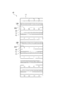
- the protruding portion 12 is not integral with the stave body 11 as in the shaft stave 10 of the first embodiment, and inside the protruding portion 12 of the first embodiment. It is different from the pipe line 17 and the connection port 17A. That is, a protrusion 32 and a pipe 37 inside thereof are provided separately from the stave body 11.
- the protrusion 32 of the shaft stave 30 is a square bar-like block formed of a high hardness material such as TiN, TiC, WC, or Ti—Al—N.
- a block may be formed of copper, a copper alloy, or other material, and the surface thereof may be coated with a high hardness material such as TiN, TiC, WC, or Ti—Al—N.
- a groove (concave portion) 32A is formed in the flat surface 13 serving as the reference surface R of the stave body 11, and the protrusion 32 described above is fitted into the groove 32A. With this configuration, the protrusion 32 protrudes from the reference surface R.
- a pipe line 37 is passed through some of the protrusions 32.
- the protrusion 32 formed with the pipe 37 is fixed by a bolt 32 ⁇ / b> C screwed from the back side of the stave body 11 (outside the blast furnace 1), as shown in FIG. 16. Further, both ends of the pipe line 37 are fixed by the connection ports 37A of the pipe line screwed in the same manner.
- bolts 32 ⁇ / b> B are screwed into the other protrusions 32 from the inside of the blast furnace 1, thereby fixing the protrusions 32.
- interval D of the projection part 32, the protrusion amount E, and thickness T are the same as that of 1st Embodiment mentioned above.
- the same effect as that of the first embodiment described above can be obtained. Furthermore, in the present embodiment, since the protrusion 32 of the shaft stave 30 and the stave body 11 are separate, the protrusion 32 of a high hardness material different from the material of the stave body 11 can be easily formed. Further, the wear resistance of the protrusion 32 can be further enhanced.
- FIG. 18 and FIG. 19 show a fourth embodiment of the present invention.
- the shaft stave 40 of this embodiment is used as the shaft stave 2B in the blast furnace 1 of the first embodiment described above.
- the structure of the blast furnace 1 is the same as that of the first embodiment, and the basic structure of the shaft stave 40 of this embodiment is the same as that of the shaft stave 10 of the first embodiment. Accordingly, the description of the common parts with the shaft stave 10 of the first embodiment will be omitted, and different parts will be described below.
- the shaft stave 40 includes a stave body 11, a bolt receiving portion 11 ⁇ / b> A, a flat surface 13, a refractory brick 15, a pipe line 16 and a connection similar to the shaft stave 10 of the first embodiment. It has a mouth 16A.
- a protruding portion 32 separate from the stave body 11 similar to the third embodiment described above is provided.
- the same effect as that of the third embodiment described above can be obtained.
- local cooling with respect to the projecting portion 32 of the shaft stave 30 of the third embodiment described above can be obtained.
- the durability of the protrusions 32 can be maintained high, so that the protrusions 32 are optimal for high load sites in the blast furnace 1 due to thermal or wear.
- the shaft stave 40 of the present embodiment has a simple structure and can be manufactured at a reduced cost because of the absence of the pipe line 37. It can be said that 40 is preferable.
- this invention is not limited to embodiment mentioned above, The deformation
- the protrusions 12 and 32 of the shaft staves 10 to 40 are continuously annular in the furnace circumferential direction in the blast furnace 1.
- it may be an annular shape that is discontinuous with each other, may be zigzag arranged at different heights, may be arranged in a spiral shape with the height changing sequentially, and the like.
- circumferential balance is important for the operation of the blast furnace 1, and consideration should be given so that symmetry is obtained with respect to the center of the blast furnace 1.
- the surface of the projection 12 of the shaft staves 10 to 40 is coated with a high hardness material, or the projection 32 is itself molded with a high hardness material.
- the use of a high hardness material is not essential.
- the shaft staves 10 to 40 protrude from the reference surface R of the stave body 11 and are susceptible to wear by the charge 4, it is desirable to ensure wear resistance by a high hardness material.
- the arrangement of the projections 12, the cross-sectional shape, the arrangement of the pipes 16 and 17, the overall shape and dimensions of the shaft staves 10 to 40, and the like may be selected as appropriate.
Landscapes
- Engineering & Computer Science (AREA)
- Chemical & Material Sciences (AREA)
- Mechanical Engineering (AREA)
- General Engineering & Computer Science (AREA)
- Manufacturing & Machinery (AREA)
- Materials Engineering (AREA)
- Metallurgy (AREA)
- Organic Chemistry (AREA)
- Blast Furnaces (AREA)
- Furnace Housings, Linings, Walls, And Ceilings (AREA)
Abstract
Description
すなわち、
(1)本発明の一態様に係るステーブは、高炉のシャフト部の内周に設けられたステーブであって、前記高炉の内部空間に面する基準面を有するステーブ本体と;前記基準面より、前記高炉の内側に向かって突出した複数の突起部と;を備える。
上記(1)に記載のステーブによれば、ステーブ本体の基準面により高炉の炉内表面が構成されるとともに、基準面から炉内側に突出する突起部によって炉内を下降する装入物が減速して基準面に沿って停滞層が形成される。停滞層はステーブ本体の基準面に対して相対速度が小さくなり、装入物の粒子によるステーブ本体の基準面の機械的な摩耗が軽減され、高炉のシャフト部を降下する粒状の装入物に対しても十分な耐久性が得られる。
上記(2)に記載のステーブによれば、突起部(突出寸法:50~150mm、間隔:200~700mm)が形成されているため、装入物が減速し、特に装入物の一部の動きが突起部によって止められ、停滞層が形成される。
このような停滞層が生じる結果、平面は停滞層で覆われる為、装入物に対する減速効果が強化される。
また、このような本ステーブでは、現状、一般的な装入物、すなわち交互に装入される8~25mm程度の粒度の鉱石系装入物と20~55mm程度の粒度のコークス系の装入物に対しては、ステーブ本体の基準面に沿って停滞層が形成されやすくなる。これにより、突起部先端の表面における装入物粒子の速度を抑制することができ、ステーブ全体の摩耗緩和効果が発揮できる。同間隔が200mmより小さいと、ステーブ本体の基準面に沿って隣接する突起部により形成された凹みが有効でなくなり、装入物が引っかかりにくい。一方、同間隔が700mmより大きいと停滞層の間隔が開き、被覆効果が十分に現れない。
上記(3)に記載のステーブによれば、炉周方向の全周に連続した突起部により、炉内の円周バランスを適切に維持することが容易であり、操業実績を良好に維持することができる。
また、突起部は、炉周方向に断続的(間欠的)に配置されていてもよい。この場合、格子状、ジグザグ状など、様々な幾何学的パターンを採用することができるが、必ず円周バランスを考慮した点対称配置とすることが好ましい。
上記(4)に記載のステーブによれば、突起部自体の摩耗防止を図ることができる。本発明の一態様のステーブにおいて、ステーブ本体の基準面は突起部により誘導される停滞層の形成(セルフライニング)により摩耗の軽減が図られるが、突起部自体は停滞層から炉内側に露出し、減速されていない装入物の粒子による摩耗を引き続き受けることもある。この場合、突起部の表面を高硬度材料で形成することにより、突起部の摩耗を抑制でき、さらには突起部により誘導される停滞層が形成される。これにより、停滞層よるステーブ本体の基準面の摩耗軽減を安定的に長期間にわたって維持することができる。
前記突起部が、前記凹部に埋め込まれ前記基準面から突出したブロックであり;
前記ブロックが高硬度材料で形成されていることが好ましい。
上記(5)に記載のステーブによれば、ステーブ本体に形成された凹部に突起部が設けられている構成、すなわち、ステーブ本体と突起部とが別体であるため、ステーブ本体の材質と異なる高硬度材料の突起部を簡単に形成することができる。
あるいは、(6)上記(4)に記載のステーブは、前記突起部が前記ステーブ本体と一体に形成されていることが好ましい。
上記(6)に記載のステーブによれば、前述した高硬度材料による突起部表面を容易に実施することができるとともに、突起部がステーブ本体と一体に形成されているため、製造が容易である。特に、突起部にも冷却用の管路を通す場合、突起部とステーブ本体とが一体であることが加工において大変有益である。
上記(7)に記載のステーブによれば、シャフト部に用いられるステーブとしての冷却効率を高めることができる。銅製または銅合金製のステーブの冷却性能は高い反面、装入物の粒子による摩耗を受けやすいが、本発明の一態様に基づく停滞層によりステーブ本体の摩耗を緩和することができる。さらには、高い冷却性能を長期間にわたり維持することができる。
上記(8)に記載のステーブによれば、ステーブ本体に設けられる通常の冷却用の管路に加えて、突起部を冷却する管路により直接的に冷却できるため、突起部の表面の硬度を高く維持することができ、摩耗防止効果を長期間にわたり維持することができる。
上記(9)に記載のステーブによれば、突起部の下方側の側面と基準面とのなす角度が90度未満であるため、傾斜した突起部によって装入物を支えやすくなる。これにより、装入物が下方に下降するのをさらに抑制することができるので、機械的な摩耗に対しても十分な耐久性が得られる。
ここで、本発明の一態様に基づくステーブは、高炉のシャフト部およびその周辺のうち、装入物が粒状のまま降下する部分に設置することが望ましい。
このようなステーブでは、粒状のまま降下する装入物があっても、ステーブの突起部により停滞層が形成され、ステーブ本体の基準面の摩耗が低減される。高炉のシャフト部においては、粒状の装入物による摩耗が進行することで、高炉としての操業が困難になる原因となるが、この部分に耐摩耗性のステーブが設置されることで、操業を安定的に行えるとともに、高炉としての寿命を延長することができる。
〔第1実施形態〕
図1において、高炉1は、基礎地盤上に構築された筒状の炉体2を有する。
炉体2は、筒状であり、上部のガス捕集マンテル3から順次炉口部S1、シャフト部S2、炉腹部S3、朝顔部S4、羽口部S5、炉底部S6に区分される。一般的に、シャフト部S2の内径は下方に向かって拡張し、炉腹部S3の内径は最大径であり、朝顔部S4の内径は下方に向かって縮小する。
炉体2には、炉底部S6の上部に羽口5が設置され、ここから熱風5Aが吹き込まれる。この熱風5Aにより、塊状帯4A中のコークスが炉内を降下するととともに順次昇温され、羽口5近傍には高温ガスによるレースウェイ5B(羽口5から高速のガスを吹き込んで羽口5前のコークスを流動化させた空隙率の高い空間)が形成される。レースウェイ5Bの高熱により、塊状帯4A中の鉄鉱石が溶融する。
融着帯4Bで溶融した鉄分6Aは滴下帯4Cを通過し、炉底部S6に向かって滴下し、溶銑6Bとして炉底部S6に溜まる。コークス等は滴下帯4Cを通過して降下し、炉底部S6に積み上がり、溶銑6Bの上に円錐形の炉芯4Dを形成する。
炉体2には、炉底部S6に出銑口6が設置され、出銑口6により炉底部S6に溜まった溶銑6Bが高炉1の外部に取り出される。
シャフト部S2の上部から中部の塊状帯4Aに面する領域S7にはシャフト用のステーブ2Bが張られる。この領域S7では、塊状帯4Aに含まれる粒状の装入物4がステーブ2Bの表面に接触しながら順次降下するため、ステーブ2Bの表面には機械的な摩耗を生じることがある。
シャフト部S2の下部から炉腹S3及び朝顔部S4を含む領域S8の内周には朝顔部および炉腹部用のステーブ2Cが貼られる。この領域S8では、融着帯4Bに含まれる高温の装入物4(融着帯根部)がステーブ2Cの表面に接触しながら順次降下するため、ステーブ2Cの表面には高温による摩耗を生じることがある。
これらのステーブ2B,2Cの高炉1の内側表面には必要に応じて耐熱レンガ2Dが張られる。また、高温の溶融鉄が貯留される炉底部には耐熱レンガ2Eが厚く積み上げられる。
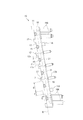
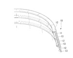
図2、図3、図4A、図4B及び図5の本実施形態において、シャフト用ステーブ10は、高炉1の内部空間に面する基準面Rを有するステーブ本体11と、基準面Rより高炉1の内側に向かって突出した複数の突起部12とを備えている。本実施形態において、突起部12がステーブ本体11と一体に形成されている。また、ステーブ本体11は、銅製または銅合金製の板材から削り出された薄板状である。シャフト用ステーブ10は銅製または銅合金製で一括鋳造された鋳物あるいは鋳鉄製であってもよい。
図2及び図3に示すように、突起部12が、ステーブ本体11の表面側には水平に連続して、複数列形成されている。この複数の突起部12の間には、図2に示すように、一段低い平面13が形成されている。平面13には1つの溝21が形成され、この溝21には耐火レンガ15が嵌め込まれている。
また、耐火レンガ15に代えて耐火キャスタブルを用いてもよい。また、溝21の数、場所はこれに限定されない。
平面13はステーブ本体11の表面からの切削により形成され、突起部12はこの切削の際に削り残されることで形成される。ここで、平面13はシャフト用ステーブ10の基準面Rであり、突起部12はシャフト用ステーブ10の基準面Rから突出している。
また、突起部12が、図4Bに示すように、高炉1内の周方向に沿って間欠的に(断続的に)配置されていてもよい。この場合、格子状、ジグザグ状など、様々な幾何学的パターンを採用することができるが、必ず円周バランスを考慮した点対称配置とすることが好ましい。なお、図4Bは、溝21を省略した図である。
なお、図2に示すように、ステーブ本体11の裏面側には、高炉1に装着するためのボルト受け部11Aが形成されている。
管路16は平面13に沿って配置され、接続口16Aから供給される冷却水によりシャフト用ステーブ10の基準面Rである平面13を冷却することが可能である。
また、突起部12の内部に、突起部12を冷却する管路17が設けられている。この構成により、接続口17Aから供給される冷却水により突起部12を冷却することが可能である。
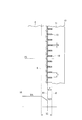
シャフト用ステーブ10の突起部12は、図2に示すように、基準面Rからの突出量(突出寸法)Eが50~150mm(平均粒度の大きいコークス系装入物の最大粒径55mmの略1~3倍)であり、高さ方向の厚みTが50~150mmであり、隣接する他の突起部12との間隔D(平面13の高さ方向寸法に相当)が200~700mm、好ましくは250~350mm(300mmの前後50mm)である。
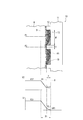
図6は本実施形態のシャフト用ステーブ10の操業時の状態(突起部の突出量E:50~150mm、間隔D:200~700mm)を模式的に示す。図6の紙面上部には本実施形態のシャフト用ステーブ10の拡大形状が模式的に示されている。また、図6の紙面下部には図6上部における横断位置P1および横断位置P2での下降速度V1,V2のグラフが示されている。
図7に、突起部12の間隔Dがきわめて大きい(突起部12の間隔D>700mm)場合を示す。図7の紙面上部にはシャフト用ステーブ10の拡大形状が模式的に示されている。また、図7の紙面下部には図7上部における横断位置P3および横断位置P4での下降速度V3,V4のグラフが示されている。
図8に、突起部12の間隔Dが小さい(突起部の間隔D<200mm)場合を示す。図8の紙面上部にはシャフト用ステーブ10の拡大形状が模式的に示されている。また、図8の紙面下部には図8上部における横断位置P5での下降速度V5のグラフが示されている。
停滞層19,18は、シャフト用ステーブ10の突起部12の上面側に生じ、基準面である平面13に沿って上方へ成長する。奥側の停滞層19の動きは殆どが停止しており、高炉1の内側の停滞層18は徐々に入れ替わりつつ、停滞層18の下降速度が非常に遅い状態である。
このような停滞層19,18が生じる結果、平面13は停滞層19,18で覆われる為、装入物4に対する減速効果が強化される。
下降速度VL2は、横断位置P1での先端面R1相当位置における下降速度VL1と同じになる。横断位置P1において、位置が先端面R1での下降速度VL1は、突起部12により形成された停滞層19,18の装入物4と下降する装入物4の境界部とで内部摩擦が大きくなり、下降速度が遅くなる。下降速度VL2は下降速度VL1の影響を受け、下降速度VL1と同じ下降速度となる。
横断位置P3における下降速度V3を見ると、高炉1の内側の平均下降速度V03は、横断位置P1における平均下降速度V01と同じであり、境界Bからシャフト用ステーブ10の基準面Rにかけて下降速度が減少する。このとき、下降速度V1と同様に下降速度は減少するが、突起部12の間隔Dがきわめて大きいため、平面13に停滞層19,18の影響は小さく、平面13の下降速度は平面13と装入物4の摩擦力となる。その結果、シャフト用ステーブ10の突起部12の間隔Dがきわめて大きい場合は、下降速度はあまり減少しない。
下降速度VL4は、横断位置P3において、相対位置における先端面R1での下降速度VL3より速くなる。横断位置P3の境界Bから基準面Rまでの断面と横断位置P4の境界Bから先端面R1までの断面とでは横断位置P4の断面の方が小さい。すなわち、横断位置P3の境界Bから基準面Rまでの距離に比べて、横断位置P4の境界Bから先端面R1までの距離の方が短いので、同じ装入物4が通過すると、下降速度VL3に比べ下降速度VL4の方の降下速度が速くなる。
このように、ステーブ10の突起部12の間隔Dがきわめて大きい場合、停滞層19,18の形成は凹部の高さWの下端部位のみに形成されるため、停滞層19,18が形成されていない部分(高さWの上端部位)では、ステーブ本体11の基準面Rである平面13に対する摩耗が大幅に増加する。
ここで、本実施形態のシャフト用ステーブ10の十分の一モデルによる試験結果により、突起部12の間隔Dの適切な範囲について説明する。
図9は、前述した図6の構成において、シャフト用ステーブ10の突起部12の間隔Dを0から120mmまで変化させ、各間隔Dにおける装入物4の基準面Rでの下降速度VW(つまりステーブ本体の基準面である平面13表面に接触する装入物4の速度)を測定したグラフである。
また、図10は、前述した図6の構成において、先端面R1での下降速度VL(つまり突起部12の先端に接触する装入物4の速度)を測定したグラフである。シャフト用ステーブ10の突起部12の厚みTは5mmとし、突出量Eについては5mmの場合と10mmの場合について測定した。図中の水平な点線は高炉1内の平均下降速度V01であり、この試験においては2.4mm/秒であった。
図10において、シャフト用ステーブ10の突起部12の先端面R1での下降速度VLは、突起部12の間隔Dが80mm以下で平均下降速度V01を下回り、間隔Dが20~70mmの範囲で十分に小さい値となり、特に、下降速度VLの最小速度のときの突起部12の間隔Dは30mmであり、この30mmの前後5mmずつである25~35mmで最も小さい値となる。また、突出量Eが15mmの場合も、突出量Eが5mm、10mmの場合と同様の下降速度VLである。
すなわち、突出量Eが15mmの場合も、高炉1の内側に適切な付着物層を形成することができる。したがって、突出量Eが10mm以上においても15mm以下であれば、セルフランニング効果を得ることができ、付着物の適正維持が可能であり、低熱負荷であり、低燃料であり、安定操業を達成しやすい。その結果、高炉1の寿命を大幅に延長することが可能である。
以上より、十分の一モデルによる試験結果を実炉換算すると、シャフト用ステーブ10の突起部12を配置するにあたっては、突起部12の各々の間隔Dが200~700mmの範囲であり、より好ましくは250~350mmの範囲であることが望ましいといえる。
シャフト用ステーブ10において、ステーブ本体11の平面13を基準面Rとして高炉1の炉内表面が構成されているので、高炉1内を下降する装入物4が減速して、基準面Rに沿って停滞層19,18が形成される。これにより、停滞層19,18の、基準面Rに対する相対速度が小さくなり、ステーブ本体11においては装入物4の粒子による基準面Rの機械的な摩耗が軽減される。したがって、高炉1内を降下する粒状の装入物に曝される部位であるシャフト部S2に本実施形態のステーブを配置することにより、シャフト部S2の上部から中部において塊状帯4Aとして降下する粒状の装入物に対しても十分な耐久性が得られる。
突起部12は、ステーブ本体11と一体に形成したため、製造が容易であり、さらに突起部12にも冷却用の管路17を通すための加工が簡略にできる。
ステーブ本体11に管路16を設けるとともに、突起部17にも管路17を設けたため、突起部12の冷却により、突起部12の表面の硬度を高く維持することができ、摩耗防止効果を長期間にわたり維持することができる。
特に、本発明に基づくシャフト用ステーブ10を、高炉1のシャフト部S2のうち、装入物4が粒状のまま塊状帯4Aとして降下する領域S7のステーブ2Bとして設置したため、粒状のまま降下する装入物4があっても、シャフト用ステーブ10の突起部12により停滞層19,18が形成され、基準面Rからの摩耗が低減される。
高炉1は、高炉1内に配置したシャフト用ステーブ10の突起部12は炉周方向の全周に連続しているため、高炉1内の円周バランスを適切に維持することが容易であり、高炉1の操業を良好に維持することができる。
図11、図12および図13には、本発明の第2実施形態が示されている。
本実施形態のシャフト用ステーブ20は、前述した第1実施形態の高炉1におけるシャフト用のステーブ2Bとして用いられる。高炉1の構成は前述した第1実施形態と同様であり、本実施形態のシャフト用ステーブ20は基本的構成が前述した第1実施形態のシャフト用ステーブ10と同様である。従って、前述した第1実施形態のステーブ10との共通部分については説明を省略し、以下には相違する部分について説明する。
この点において、前述した第1実施形態のシャフト用ステーブ10の、突起部12に対する局部的な冷却が得られる。それにより、突起部12の耐久性を高く維持できるため、高炉1内の熱的あるいは摩耗において高負荷の部位に最適である。一方、本実施形態のシャフト用ステーブ20は、管路17がない分、構造が簡略かつ製造コストも低減でき、突起部12に対する熱的あるいは摩耗において負荷がさほど要求されない部位には、シャフト用ステーブ20のほうが好ましいといえる。
図14、図15および図16には、本発明の第3実施形態が示されている。
本実施形態のシャフト用ステーブ30は、前述した第1実施形態の高炉1におけるシャフト用のステーブ2Bとして用いられる。高炉1の構成は前記第1実施形態と同様であり、本実施形態のステーブ30は基本的構成が前記第1実施形態のシャフト用ステーブ10と同様である。従って、前記第1実施形態のシャフト用ステーブ10との共通部分については説明を省略し、以下には相違する部分について説明する。
ステーブ本体11の基準面Rとなる平面13に溝(凹部)32Aが形成されており、この溝32Aに前述した突起部32が嵌め込まれる。この構成により、基準面Rから突起部32が突出している。
他の突起部32には、図14及び図15に示すように、高炉1の内側からボルト32Bがねじ込まれ、これにより突起部32の固定が行われている。
なお、ステーブ本体11に嵌め込まれた状態において、突起部32の間隔D、突出量E、厚みTは前述した第1実施形態と同様である。
さらに、本実施形態においては、シャフト用ステーブ30の突起部32とステーブ本体11とが別体であるため、ステーブ本体11の材質と異なる高硬度材料の突起部32を簡単に形成することができ、突起部32の耐摩耗性を一層高めることもできる。
図17、図18および図19には、本発明の第4実施形態が示されている。
本実施形態のシャフト用ステーブ40は、前述した第1実施形態の高炉1におけるシャフト用のステーブ2Bとして用いられる。高炉1の構成は前記第1実施形態と同様であり、本実施形態のシャフト用ステーブ40は基本的構成が前記第1実施形態のシャフト用ステーブ10と同様である。従って、前記第1実施形態のシャフト用ステーブ10との共通部分については説明を省略し、以下には相違する部分について説明する。
この点において、前述した第3実施形態のシャフト用ステーブ30の、突起部32に対する局部的な冷却が得られる。それにより突起部32の耐久性を高く維持できるため、高炉1内の熱的あるいは摩耗において高負荷の部位に最適である。一方、本実施形態のシャフト用ステーブ40は、管路37がない分、構造が簡略かつ製造コストも低減でき、突起部32に対する熱的あるいは摩耗において負荷がさほど要求されない部位には、シャフト用ステーブ40のほうが好ましいといえる。
なお、本発明は前述した実施形態に限定されなく、本発明の目的を達成できる範囲内での変形等をも含む。
前記実施形態では、高炉1内にステーブ10~40を配列した際に、各々のシャフト用ステーブ10~40の突起部12,32が高炉1内の炉周方向で連続して円環状となるようにしたが、互いに不連続な円環状であってもよく、異なる高さにジグザグに配列されていても良く、順次高さが変化して螺旋状に並ぶ等であってもよい。但し、高炉1の操業上、円周バランスが重要であり、高炉1の中心に対して対称性が得られるように配慮するべきである。
その他、突起部12の配置、断面形状、管路16,17の配置、シャフト用ステーブ10~40の全体的な形状、寸法等は実施にあたって適宜選択すればよい。
2…炉体
2A…鉄皮
2B,2C…ステーブ
2D,2E…耐熱レンガ
3…ガス捕集マンテル
4…装入物
4A…塊状帯
4B…融着帯
4C…滴下帯
4D…炉芯
5…羽口
5A…熱風
5B…レースウェイ
6…出銑口
6A…鉄分
6B…溶銑
10~40…シャフト用ステーブ
11…ステーブ本体
11A…ボルト受け部
12,32…突起部
13…平面
15…耐火レンガ
16,17,37…冷却用の管路
16A,17A,37A…接続口
19,18…停滞層
32A…溝
32B,32C…ボルト
B…境界
D…間隔
E…突出量
R…基準面
R1…先端面
S1…炉口部
S2…シャフト部
S3…炉腹部
S4…朝顔部
S6…炉底部
S7…シャフト用ステーブの設置領域
S8…朝顔用ステーブの設置領域
V01~V05…平均下降速度
V1~V5…下降速度
VL~VL5…突起部先端での下降速度
VW~VW3…基準面での下降速度
Claims (10)
- 高炉のシャフト部の内周に設けられたステーブであって、
前記高炉の内部空間に面する基準面を有するステーブ本体と;
前記基準面より、前記高炉の内側に向かって突出した複数の突起部と;
を備えることを特徴とするステーブ。 - 前記突起部の突出寸法が50~150mmであり;
隣接する前記突起部の間隔が200~700mmである;
ことを特徴とする請求項1に記載のステーブ。 - 前記突起部が、前記高炉の周方向に沿って連続的、または、断続的に設けられていることを特徴とする請求項1に記載のステーブ。
- 前記突起部の表面が高硬度材料で形成されていることを特徴とする請求項1に記載のステーブ。
- 前記ステーブ本体に凹部が形成され;
前記突起部が、前記凹部に埋め込まれ前記基準面から突出したブロックであり;
前記ブロックが高硬度材料で形成されている;
ことを特徴とする請求項4に記載のステーブ。 - 前記突起部が前記ステーブ本体と一体に形成されていることを特徴とする請求項4に記載のステーブ。
- 前記ステーブ本体が銅または銅合金であることを特徴とする請求項1に記載のステーブ。
- 前記突起部の内部に、前記突起部を冷却する管路が設けられていることを特徴とする請求項1に記載のステーブ。
- 前記基準面の両端側に設けられた前記突起部の対向する2つの側面のうち、前記突起部の下方側の側面と前記基準面とのなす角度が90度未満であることを特徴とする請求項1に記載のステーブ。
- 請求項1から請求項9のいずれか1項に記載のステーブを備えたことを特徴とする高炉。
Priority Applications (4)
| Application Number | Priority Date | Filing Date | Title |
|---|---|---|---|
| CN201180010340.7A CN102770563B (zh) | 2010-02-23 | 2011-02-22 | 冷却壁及高炉 |
| KR1020127022439A KR101337108B1 (ko) | 2010-02-23 | 2011-02-22 | 스테이브 및 고로 |
| BR112012020858A BR112012020858A2 (pt) | 2010-02-23 | 2011-02-22 | aduela e alto-forno. |
| JP2012501776A JP5093420B2 (ja) | 2010-02-23 | 2011-02-22 | ステーブおよび高炉 |
Applications Claiming Priority (2)
| Application Number | Priority Date | Filing Date | Title |
|---|---|---|---|
| JP2010-036841 | 2010-02-23 | ||
| JP2010036841 | 2010-02-23 |
Publications (1)
| Publication Number | Publication Date |
|---|---|
| WO2011105346A1 true WO2011105346A1 (ja) | 2011-09-01 |
Family
ID=44506754
Family Applications (1)
| Application Number | Title | Priority Date | Filing Date |
|---|---|---|---|
| PCT/JP2011/053772 Ceased WO2011105346A1 (ja) | 2010-02-23 | 2011-02-22 | ステーブおよび高炉 |
Country Status (5)
| Country | Link |
|---|---|
| JP (1) | JP5093420B2 (ja) |
| KR (1) | KR101337108B1 (ja) |
| CN (1) | CN102770563B (ja) |
| BR (1) | BR112012020858A2 (ja) |
| WO (1) | WO2011105346A1 (ja) |
Cited By (2)
| Publication number | Priority date | Publication date | Assignee | Title |
|---|---|---|---|---|
| JP2011219825A (ja) * | 2010-04-09 | 2011-11-04 | Nippon Steel Engineering Co Ltd | ステーブクーラ |
| WO2018122590A1 (en) * | 2016-12-30 | 2018-07-05 | Arcelormittal | Copper cooling plate with wear resistant inserts, for a blast furnace |
Families Citing this family (5)
| Publication number | Priority date | Publication date | Assignee | Title |
|---|---|---|---|---|
| KR101870708B1 (ko) | 2016-12-05 | 2018-07-19 | 주식회사 포스코 | 블록 구조체, 용기 및 블록 구조체의 시공 방법 |
| KR102083533B1 (ko) | 2017-11-21 | 2020-03-02 | 주식회사 포스코 | 처리 장치 |
| CN109280728A (zh) * | 2018-11-07 | 2019-01-29 | 中冶赛迪工程技术股份有限公司 | 一种高炉冷却壁结构 |
| KR102283224B1 (ko) * | 2019-02-19 | 2021-07-29 | 주식회사 서울엔지니어링 | 스테이브 및 스테이브의 제조방법 |
| JP7588311B2 (ja) * | 2019-05-09 | 2024-11-22 | セカル テクノ インダストリア エ コメーシオ デ エクイパメントス ソブ エンコメンダ リミターダ | 高炉向け多重チャネル冷却パネル |
Citations (5)
| Publication number | Priority date | Publication date | Assignee | Title |
|---|---|---|---|---|
| JPH0394008A (ja) * | 1989-09-05 | 1991-04-18 | Sumitomo Metal Ind Ltd | 新設用高炉のステーブクーラ |
| JPH10195512A (ja) * | 1996-12-27 | 1998-07-28 | Sumitomo Metal Ind Ltd | 高炉緩冷却装置の設計方法 |
| JP2002275515A (ja) * | 2001-03-21 | 2002-09-25 | Nkk Corp | ステーブおよびステーブの厚さ測定方法 |
| JP2004307899A (ja) * | 2003-04-03 | 2004-11-04 | Sumitomo Metal Ind Ltd | ステーブクーラ |
| JP2006037223A (ja) * | 2004-07-23 | 2006-02-09 | Km Europ Metal Ag | 冷却プレート |
Family Cites Families (9)
| Publication number | Priority date | Publication date | Assignee | Title |
|---|---|---|---|---|
| SU148420A1 (ru) * | 1961-04-13 | 1978-09-15 | Groshin V A | Футеровка доменной печи |
| JPS50137305U (ja) * | 1974-04-30 | 1975-11-12 | ||
| FR2493871A1 (fr) * | 1980-11-07 | 1982-05-14 | Usinor | Plaques de refroidissement pour hauts fourneaux |
| JP2635896B2 (ja) * | 1992-09-08 | 1997-07-30 | シーケーディ株式会社 | 形状可変アクチュエータ |
| CN2545210Y (zh) * | 2002-05-31 | 2003-04-16 | 佘京鹏 | 齿形挂渣槽结构的铜板冷却壁 |
| CN2879083Y (zh) * | 2005-10-31 | 2007-03-14 | 佘京鹏 | 整体式多凸台铜冷却壁 |
| CN201158670Y (zh) * | 2008-02-28 | 2008-12-03 | 上海宝钢铸造有限公司 | 炼铁炉冷却壁镶砖构造 |
| CN201381329Y (zh) * | 2008-12-10 | 2010-01-13 | 武汉钢铁(集团)公司 | 一种高炉铜冷却壁 |
| JP4897115B2 (ja) * | 2009-11-19 | 2012-03-14 | 新日本製鐵株式会社 | ステーブ、高炉及び高炉の運転方法 |
-
2011
- 2011-02-22 KR KR1020127022439A patent/KR101337108B1/ko active Active
- 2011-02-22 BR BR112012020858A patent/BR112012020858A2/pt not_active Application Discontinuation
- 2011-02-22 WO PCT/JP2011/053772 patent/WO2011105346A1/ja not_active Ceased
- 2011-02-22 JP JP2012501776A patent/JP5093420B2/ja active Active
- 2011-02-22 CN CN201180010340.7A patent/CN102770563B/zh active Active
Patent Citations (5)
| Publication number | Priority date | Publication date | Assignee | Title |
|---|---|---|---|---|
| JPH0394008A (ja) * | 1989-09-05 | 1991-04-18 | Sumitomo Metal Ind Ltd | 新設用高炉のステーブクーラ |
| JPH10195512A (ja) * | 1996-12-27 | 1998-07-28 | Sumitomo Metal Ind Ltd | 高炉緩冷却装置の設計方法 |
| JP2002275515A (ja) * | 2001-03-21 | 2002-09-25 | Nkk Corp | ステーブおよびステーブの厚さ測定方法 |
| JP2004307899A (ja) * | 2003-04-03 | 2004-11-04 | Sumitomo Metal Ind Ltd | ステーブクーラ |
| JP2006037223A (ja) * | 2004-07-23 | 2006-02-09 | Km Europ Metal Ag | 冷却プレート |
Cited By (3)
| Publication number | Priority date | Publication date | Assignee | Title |
|---|---|---|---|---|
| JP2011219825A (ja) * | 2010-04-09 | 2011-11-04 | Nippon Steel Engineering Co Ltd | ステーブクーラ |
| WO2018122590A1 (en) * | 2016-12-30 | 2018-07-05 | Arcelormittal | Copper cooling plate with wear resistant inserts, for a blast furnace |
| US11150020B2 (en) | 2016-12-30 | 2021-10-19 | Arcelormittal | Copper cooling plate with wear resistant inserts, for a blast furnace |
Also Published As
| Publication number | Publication date |
|---|---|
| CN102770563B (zh) | 2014-03-12 |
| JPWO2011105346A1 (ja) | 2013-06-20 |
| JP5093420B2 (ja) | 2012-12-12 |
| BR112012020858A2 (pt) | 2016-08-23 |
| CN102770563A (zh) | 2012-11-07 |
| KR20120101736A (ko) | 2012-09-14 |
| KR101337108B1 (ko) | 2013-12-05 |
Similar Documents
| Publication | Publication Date | Title |
|---|---|---|
| JP5093420B2 (ja) | ステーブおよび高炉 | |
| JP4897115B2 (ja) | ステーブ、高炉及び高炉の運転方法 | |
| CN102395688B (zh) | 用于冶金炉的冷却板及冶金炉以及制造冷却板的方法 | |
| JP2010215993A (ja) | 内部水冷式高炉羽口 | |
| JP2014227564A (ja) | ステーブクーラーおよびこのステーブクーラーを備えた高炉 | |
| JP2011141089A5 (ja) | ||
| JP6102472B2 (ja) | ステーブおよび高炉 | |
| CN202246778U (zh) | 一种组合式炉篦条 | |
| CN201686709U (zh) | 一种耐磨陶瓷无料钟高炉布料溜槽 | |
| US11319604B2 (en) | Copper cooling plate with multilayer protrusions comprising wear resistant material, for a blast furnace | |
| JP4757960B2 (ja) | 高炉朝顔部構造およびその設計方法 | |
| JP2016000868A (ja) | ステーブクーラー | |
| JP4294206B2 (ja) | 高炉炉壁構造および高炉の操業方法 | |
| CN115752327B (zh) | 一种铁矿氧化球团回转窑结圈物厚度的检测系统及方法 | |
| CN210700358U (zh) | 一种烧结矿倒料箱的溜板结构 | |
| JP5461831B2 (ja) | シンターケーキ支持スタンド | |
| JP2014173164A (ja) | ステーブクーラーおよびこのステーブクーラーを備えた高炉 | |
| JPH05295410A (ja) | 高炉操業方法 | |
| JP2000073110A (ja) | 高炉用ステーブクーラー | |
| CN112833674A (zh) | 一种矿热炉长寿命布料溜槽 | |
| JPH0442444B2 (ja) | ||
| JP2011111631A (ja) | 高炉操業方法 | |
| JP2014173095A (ja) | ステーブクーラーおよびこのステーブクーラーを備えた高炉 | |
| JP2018044230A (ja) | 高炉朝顔部構造および高炉の設計方法 | |
| JP2000345221A (ja) | クーリングステーブ |
Legal Events
| Date | Code | Title | Description |
|---|---|---|---|
| WWE | Wipo information: entry into national phase |
Ref document number: 201180010340.7 Country of ref document: CN |
|
| 121 | Ep: the epo has been informed by wipo that ep was designated in this application |
Ref document number: 11747307 Country of ref document: EP Kind code of ref document: A1 |
|
| WWE | Wipo information: entry into national phase |
Ref document number: 2012501776 Country of ref document: JP |
|
| DPE1 | Request for preliminary examination filed after expiration of 19th month from priority date (pct application filed from 20040101) | ||
| WWE | Wipo information: entry into national phase |
Ref document number: 7069/DELNP/2012 Country of ref document: IN |
|
| NENP | Non-entry into the national phase |
Ref country code: DE |
|
| ENP | Entry into the national phase |
Ref document number: 20127022439 Country of ref document: KR Kind code of ref document: A |
|
| 122 | Ep: pct application non-entry in european phase |
Ref document number: 11747307 Country of ref document: EP Kind code of ref document: A1 |
|
| REG | Reference to national code |
Ref country code: BR Ref legal event code: B01A Ref document number: 112012020858 Country of ref document: BR |
|
| ENP | Entry into the national phase |
Ref document number: 112012020858 Country of ref document: BR Kind code of ref document: A2 Effective date: 20120820 |