WO2011104834A1 - Dispositif de conditionnement d'air - Google Patents
Dispositif de conditionnement d'air Download PDFInfo
- Publication number
- WO2011104834A1 WO2011104834A1 PCT/JP2010/052892 JP2010052892W WO2011104834A1 WO 2011104834 A1 WO2011104834 A1 WO 2011104834A1 JP 2010052892 W JP2010052892 W JP 2010052892W WO 2011104834 A1 WO2011104834 A1 WO 2011104834A1
- Authority
- WO
- WIPO (PCT)
- Prior art keywords
- heat exchanger
- refrigerant
- side heat
- cycle
- compressor
- Prior art date
Links
Images


Classifications
-
- F—MECHANICAL ENGINEERING; LIGHTING; HEATING; WEAPONS; BLASTING
- F24—HEATING; RANGES; VENTILATING
- F24F—AIR-CONDITIONING; AIR-HUMIDIFICATION; VENTILATION; USE OF AIR CURRENTS FOR SCREENING
- F24F5/00—Air-conditioning systems or apparatus not covered by F24F1/00 or F24F3/00, e.g. using solar heat or combined with household units such as an oven or water heater
- F24F5/0003—Exclusively-fluid systems
-
- F—MECHANICAL ENGINEERING; LIGHTING; HEATING; WEAPONS; BLASTING
- F25—REFRIGERATION OR COOLING; COMBINED HEATING AND REFRIGERATION SYSTEMS; HEAT PUMP SYSTEMS; MANUFACTURE OR STORAGE OF ICE; LIQUEFACTION SOLIDIFICATION OF GASES
- F25B—REFRIGERATION MACHINES, PLANTS OR SYSTEMS; COMBINED HEATING AND REFRIGERATION SYSTEMS; HEAT PUMP SYSTEMS
- F25B13/00—Compression machines, plants or systems, with reversible cycle
-
- F—MECHANICAL ENGINEERING; LIGHTING; HEATING; WEAPONS; BLASTING
- F25—REFRIGERATION OR COOLING; COMBINED HEATING AND REFRIGERATION SYSTEMS; HEAT PUMP SYSTEMS; MANUFACTURE OR STORAGE OF ICE; LIQUEFACTION SOLIDIFICATION OF GASES
- F25B—REFRIGERATION MACHINES, PLANTS OR SYSTEMS; COMBINED HEATING AND REFRIGERATION SYSTEMS; HEAT PUMP SYSTEMS
- F25B25/00—Machines, plants or systems, using a combination of modes of operation covered by two or more of the groups F25B1/00 - F25B23/00
- F25B25/005—Machines, plants or systems, using a combination of modes of operation covered by two or more of the groups F25B1/00 - F25B23/00 using primary and secondary systems
-
- F—MECHANICAL ENGINEERING; LIGHTING; HEATING; WEAPONS; BLASTING
- F25—REFRIGERATION OR COOLING; COMBINED HEATING AND REFRIGERATION SYSTEMS; HEAT PUMP SYSTEMS; MANUFACTURE OR STORAGE OF ICE; LIQUEFACTION SOLIDIFICATION OF GASES
- F25B—REFRIGERATION MACHINES, PLANTS OR SYSTEMS; COMBINED HEATING AND REFRIGERATION SYSTEMS; HEAT PUMP SYSTEMS
- F25B41/00—Fluid-circulation arrangements
-
- F—MECHANICAL ENGINEERING; LIGHTING; HEATING; WEAPONS; BLASTING
- F25—REFRIGERATION OR COOLING; COMBINED HEATING AND REFRIGERATION SYSTEMS; HEAT PUMP SYSTEMS; MANUFACTURE OR STORAGE OF ICE; LIQUEFACTION SOLIDIFICATION OF GASES
- F25B—REFRIGERATION MACHINES, PLANTS OR SYSTEMS; COMBINED HEATING AND REFRIGERATION SYSTEMS; HEAT PUMP SYSTEMS
- F25B2313/00—Compression machines, plants or systems with reversible cycle not otherwise provided for
- F25B2313/027—Compression machines, plants or systems with reversible cycle not otherwise provided for characterised by the reversing means
- F25B2313/02742—Compression machines, plants or systems with reversible cycle not otherwise provided for characterised by the reversing means using two four-way valves
Definitions
- the present invention relates to an air conditioner installed in, for example, a house or an office building, and in particular, includes a natural circulation cycle in which refrigerant naturally circulates due to a density difference and a compression cycle in which refrigerant is forced to circulate by a compressor.
- the present invention relates to an air conditioner that can be used side by side and can selectively use these two refrigeration cycles.
- Patent Document 1 discloses a compressor, a reheat condenser, and a cooler for cooling the air in the box.
- Refrigeration cycle compression cycle
- natural circulation cooling condenser natural circulation cooling system
- condensers for natural circulation cooling and natural circulation cooling coolers natural And a cycle-type cycle
- Patent Document 2 discloses a natural refrigerant cooling system including an indoor heat exchanger, an outdoor heat exchanger, a refrigerant pipe, an expansion valve, and a refrigerant compression forced circulation device corresponding to a compression refrigerator of another device.
- a dehumidifying device is disclosed.
- This natural circulation cooling dehumidification device is a natural circulation cycle formed by connecting an outdoor heat exchanger, an indoor heat exchanger at a position lower than the outdoor heat exchanger, and an expansion valve in an annular shape with refrigerant piping. And a compression cycle using a refrigerant compression forced circulation device, and an evaporative heat exchanger of the compression cycle is tightly coupled to an outdoor heat exchanger of the natural circulation cycle.
- the evaporative heat exchanger can efficiently take heat from the outdoor heat exchanger, even when the temperature difference between the indoor and the outdoor is eliminated and the cooling and dehumidifying capacity is reduced.
- the refrigerant compression forced circulation device it is possible to compensate for a decrease in the cooling and dehumidifying capability of the refrigerant natural circulation cooling and dehumidifying device.
- Patent Document 2 a refrigerant natural circulation cooling and dehumidifying device (natural circulation type cycle) using refrigerant natural circulation is added to a refrigerant compression forced circulation cooling / heating device (compression type cycle) using a refrigerant compression forced circulation system.
- An air conditioning apparatus is disclosed. According to this air conditioner, it is possible to perform a high-quality dry operation mode in which heating is performed by the refrigerant compression forced circulation cooling / heating dual-purpose device while dehumidification is performed by the refrigerant natural circulation cooling / dehumidifying device, thereby improving comfort. it can.
- JP 2003-121072 A Japanese Patent Laid-Open No. 10-300128
- the natural circulation cycle and the compression cycle constitute an independent refrigeration cycle. Therefore, the heat exchanger of the natural circulation cycle is connected to the compression cycle at the peak of air conditioning. It was impossible to use as a heat exchanger. Therefore, the subject that the heat exchange function of the heat exchanger of a natural circulation type cycle was not utilized effectively occurred.
- the natural circulation type cycle is a cycle in which a head difference is provided between two heat exchangers, and the refrigerant naturally circulates due to a density difference.
- the difference between the room temperature and the room temperature is small, there is a problem that the dehumidifying ability cannot be obtained even if the cooling operation using the natural circulation type cycle is performed.
- the present invention has been made in view of the above-described circumstances, and an object of the present invention is to provide a natural circulation cycle heat exchanger for a compression cycle in an air conditioner provided with a compression cycle and a natural circulation cycle. It is to be used as a heat exchanger to exhibit air conditioning capability.
- the present invention also provides an air conditioning system that can enhance the dehumidification capability even when the difference between the outside air temperature and the room temperature is small by using both the natural circulation cycle and the compression cycle when the outside air temperature is equal to or lower than the room temperature. It is also an object to provide an apparatus.
- an air conditioner of the present invention includes a compressor, first and second heat source side heat exchangers that exchange heat between the heat transfer medium on the heat source side and the refrigerant, and heat on the use side.
- An air conditioner including first and second usage-side heat exchangers that exchange heat between the transport medium and the refrigerant, a flow path switching valve that switches a flow path direction of the refrigerant, and first and second expansion valves
- the first heat source side heat exchanger, the first expansion valve, and the first heat source side heat exchanger installed at a position lower than the first heat source side heat exchanger are sequentially refrigerant.
- a natural circulation cycle that is formed in an annular shape by connecting with piping, and the refrigerant circulates naturally due to a density difference, a discharge port of the compressor, the flow path switching valve, the second heat source side heat exchanger, the second The expansion valve, the second user-side heat exchanger, and the suction port of the compressor are sequentially connected by refrigerant piping.
- a first compression cycle in which the refrigerant is forcedly circulated by the compressor, a discharge port of the compressor, the flow path switching valve, the second heat source side heat exchanger, the first The heat source side heat exchanger, the first expansion valve, the first usage side heat exchanger, the second usage side heat exchanger, and the compressor suction port are sequentially connected by a refrigerant pipe to form an annular shape.
- Cycle switching means for switching the refrigeration cycle between the first state to be formed and the second state in which the second compression cycle is formed is provided.
- the heat exchanger of the natural circulation cycle can be used as the heat exchanger of the second compression cycle.
- a large effect is exhibited at the peak of air conditioning.
- this invention is a pipe
- the use side heat transfer medium circulation circuit is provided, and the air in the space to be cooled is cooled and heated via the indoor heat exchanger installed in the space to be cooled.
- Refrigerant piping connecting the indoor unit and the outdoor unit is not necessary, and the amount of refrigerant is small.
- the outdoor unit when a natural circulation cycle is formed in a conventional configuration in which an indoor unit and an outdoor unit are connected by a refrigerant pipe, the outdoor unit must be installed at a higher position than the indoor unit, and layout restrictions are imposed. was there.
- the use side heat transfer medium circulation circuit is provided, there is an advantage that the degree of freedom in layout increases.
- this invention divides the said 2nd utilization side heat exchanger into the 1st division
- the reheat dehumidifying operation for dehumidifying the air in the space to be cooled can be performed by the first divided heat exchanger, the second divided heat exchanger, and the third expansion valve.
- the dehumidifying capacity can be increased even when the outside air temperature is equal to or lower than the room temperature and the difference between the outside temperature and the room temperature is small. it can.
- the present invention is the above configuration, wherein the second heat source side heat exchanger and the heat storage tank are connected by a heat source side heat transfer medium pipe to form an annular heat source side heat transfer medium circulation circuit, and the heat source side
- the heat transfer medium circulation circuit is characterized in that water as the heat transfer medium on the heat source side is forcibly circulated.
- the intermediate hot water can be made using the exhaust heat of the heat source side heat exchanger, the efficiency is improved by using this intermediate hot water for hot water supply or the like. Furthermore, in the present invention, since the exhaust heat of the heat source side heat exchanger can be stored by the heat storage tank, for example, it is possible to eliminate the difference between the time zones of the air conditioning load and the hot water supply load.
- the hot water supply compressor, the hot water use side heat exchanger, the hot water supply expansion valve, and the second heat source side heat exchanger are sequentially connected by the hot water supply refrigerant pipe.
- An annular hot water supply cycle is formed, and hot water supply refrigerant as a heat transfer medium on the heat source side is forcibly circulated by the hot water supply compressor in the hot water supply cycle.
- hot water having a temperature higher than that of the intermediate hot water can be generated.
- the present invention provides a bypass pipe that bypasses the suction port and the discharge port of the compressor, a refrigerant flow path, a flow path that passes through the compressor, and a flow path that passes through the bypass pipe. And a bypass opening / closing means for switching between the flow paths.
- a natural circulation cycle using two heat source side heat exchangers and two utilization side heat exchangers can be formed, it is possible to operate with a natural circulation cycle with high heat exchange efficiency, and to save energy. Can be planned.
- the heat exchanger of the natural circulation type cycle can be used as the heat exchanger of the compression type cycle, so that the heat transfer area of the heat exchanger is larger than that using only the heat exchanger of the compression type cycle. Becomes wider, heat exchange efficiency is improved, and energy can be saved.
- the natural circulation cycle and the compression cycle can be used in combination, the dehumidifying ability can be increased even when the outside air temperature is equal to or lower than the room temperature and the temperature difference between the outside temperature and the room temperature is small.
- FIG. 6 is an operation diagram showing the flow of the refrigerant and the heat transfer medium in FIG.
- the operation mode No. of the air conditioner according to the first embodiment of the present invention is described.
- 3 is an operation diagram showing the flow of the refrigerant and the heat transfer medium in FIG. The operation mode No. of the air conditioner according to the first embodiment of the present invention is described.
- 6 is an operation diagram showing the flow of the refrigerant and the heat transfer medium in FIG. It is a basic block diagram showing each component which comprises the air conditioning apparatus which concerns on the 2nd Example of this invention, and those connection relations.
- the operation mode No. of the air conditioner according to the second embodiment of the present invention is described.
- 6 is an operation diagram showing the flow of the refrigerant and the heat transfer medium in FIG. It is a basic block diagram showing each component which comprises the air conditioning apparatus which concerns on the 3rd Example of this invention, and those connection relations.
- the operation mode No. of the air conditioner according to the third embodiment of the present invention is described.
- 6 is an operation diagram showing the flow of the refrigerant and the heat transfer medium in FIG.
- FIG. 7 is an operation diagram showing the flow of the refrigerant and the heat transfer medium in FIG.
- the operation mode No. of the air conditioner according to the third embodiment of the present invention is described.
- 8 is an operation diagram showing the flow of the refrigerant and the heat transfer medium in FIG.
- the operation mode No. of the air conditioner according to the third embodiment of the present invention is described.
- 9 is an operation diagram showing the flow of the refrigerant and the heat transfer medium in FIG.
- the operation mode No. of the air conditioner according to the third embodiment of the present invention is described.
- 10 is an operation diagram showing the flow of the refrigerant and the heat transfer medium in FIG.
- the operation mode No. of the air conditioner according to the third embodiment of the present invention is described.
- 11 is an operation diagram showing the flow of the refrigerant and the heat transfer medium in FIG. It is a basic block diagram showing each component which comprises the air conditioning apparatus which concerns on the 4th Example of this invention, and those connection relations.
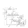
- FIG. 1 is a variable capacity compressor for refrigerant
- 2 is a four-way valve for compression cycle (flow path switching valve)
- 3 is a four-way valve for cycle switching (cycle switching means)
- 4 is the atmosphere (heat source side)
- First heat source side heat exchanger that exchanges heat between the refrigerant and the refrigerant
- 5 is a first expansion valve
- 6 is a first that exchanges heat between the water (the heat carrier medium on the use side) and the refrigerant.
- a heat exchanger on the use side, 7 is a second heat source side heat exchanger that exchanges heat between the atmosphere (heat transfer medium on the heat source side) and the refrigerant
- 8 is a heat exchange between water (heat transfer medium on the use side) and the refrigerant.
- the 2nd utilization side heat exchanger to be made to represent, 9 represents the 2nd expansion valve, respectively.
- the first use side heat exchanger 6 is installed at a position lower than the first heat source side heat exchanger 4. That is, a head difference is provided between the first use side heat exchanger 6 and the first heat source side heat exchanger 4.
- R410A is used as the refrigerant.
- the first heat source side heat exchanger 4 and the first expansion valve 5 are connected by a refrigerant pipe 14, and the first expansion valve 5 and the first usage side heat exchanger 6 are connected to the refrigerant pipe.
- the first use side heat exchanger 6 and the cycle switching four-way valve 3 are connected by the refrigerant pipe 16
- the cycle switching four-way valve 3 and the first heat source side heat exchanger 4 are connected by the refrigerant pipe 13. It is a refrigeration cycle that is connected and formed in an annular shape. The refrigerant naturally circulates in the natural circulation cycle due to the density difference.
- the discharge port 1b of the compressor 1 and the compression cycle four-way valve 2 are connected by a refrigerant pipe 10, and the compression cycle four-way valve 2 and the second heat source side heat exchanger 7 are connected.
- the refrigerant pipe 11 connects, the second heat source side heat exchanger 7 and the cycle switching four-way valve 3 are connected by the refrigerant pipe 12, and the cycle switching four-way valve 3 and the second expansion valve 9 are connected by the refrigerant pipe 17.
- the second expansion valve 9 and the second use side heat exchanger 8 are connected by the refrigerant pipe 18, and the second use side heat exchanger 8 and the compression cycle four-way valve 2 are connected by the refrigerant pipe 19.
- the discharge port 1b of the compressor 1 and the compression cycle four-way valve 2 are connected by a refrigerant pipe 10, and the compression cycle four-way valve 2 and the second heat source side heat exchanger 7 are connected.
- the refrigerant pipe 11 is connected
- the second heat source side heat exchanger 7 and the cycle switching four-way valve 3 are connected by the refrigerant pipe 12
- the cycle switching four-way valve 3 and the first heat source side heat exchanger 4 are connected to the refrigerant pipe.
- the first heat source side heat exchanger 4 and the first expansion valve 5 are connected by a refrigerant pipe 14
- the first expansion valve 5 and the first use side heat exchanger 6 are connected by a refrigerant pipe 15.
- the first use side heat exchanger 6 and the cycle switching four-way valve 3 are connected by the refrigerant pipe 16
- the cycle switching four-way valve 3 and the second expansion valve 9 are connected by the refrigerant pipe 17, and the second
- the expansion valve 9 and the second use side heat exchanger 8 are connected by a refrigerant pipe 18, and the second use side heat exchanger 8 and the compression type heat exchanger 8 are connected.
- Le four-way valve 2 are connected by refrigerant pipe 19
- the compression-type cycle four-way valve 2 inlet 1a of the compressor 1 is connected to a refrigeration cycle formed annularly refrigerant pipe 20. Then, the compressor 1 forcibly circulates the refrigerant in the second compression cycle PC2.
- Cycle switching among the natural circulation cycle TS1, the first compression cycle PC1 and the second compression cycle PC2 is performed by operating the cycle switching four-way valve 3. More specifically, when the cycle switching four-way valve 3 is operated so that the refrigerant pipe 13 and the refrigerant pipe 16 communicate with each other and the refrigerant pipe 12 and the refrigerant pipe 17 communicate with each other, Two independent refrigeration cycles are formed, a circulation cycle TS1 and a first compression cycle PC1. That is, two refrigeration cycles of the natural circulation type cycle TS1 and the first compression type cycle PC1 are simultaneously formed.
- the air conditioner according to the first embodiment can operate the natural circulation cycle TS1 and the first compression cycle PC1 at the same time by operating the cycle switching four-way valve 4.
- two states can be created: a state where only the second compression cycle PC2 can be used.
- Numeral 30 is a house, 31 is an indoor heat exchanger installed in the room (cooled space), 32 is a circulation pump, and 33 is a cold / hot water circuit four-way valve.
- the cold / hot water circulation circuit (use-side heat transfer medium circulation circuit) CW connects the indoor heat exchanger 31 and the circulation pump 32 with a cold / hot water pipe (use-side heat transfer medium pipe) 35, and the circulation pump 32 and the cold / hot water circuit use.
- the four-way valve 33 is connected by the cold / hot water pipe 36, the cold / hot water circuit four-way valve 33 and the second use side heat exchanger 8 are connected by the cold / hot water pipe 37, and the second use side heat exchanger 8 and the first
- the use side heat exchanger 6 is connected by a cold / hot water pipe 38, the first use side heat exchanger 6 and the cold / hot water circuit four-way valve 33 are connected by a cold / hot water pipe 39, and the cold / hot water circuit four-way valve 33 is connected.
- This is a circuit formed in an annular shape by connecting the indoor heat exchanger 31 with a cold / hot water pipe 40. Then, the circulation pump 32 forces water to circulate in the cold / hot water circulation circuit CW.
- the operation mode No. 1-No. 4 four operation modes can be performed.
- hs is an abbreviation for heat source
- app is application
- H Humidity
- Operation mode No. 1 (Fig. 2) Operation mode No.
- Reference numeral 1 denotes a cooling operation mode in which the second compression cycle PC2 is used alone, and is an operation mode used when the outside air temperature is high and the cooling load is large, such as in the daytime in summer.
- This mode is used for This operation mode No. 1, the refrigerant circulation path is in the direction of the arrow in FIG.
- the refrigerant pipe 10 and the refrigerant pipe 11 are communicated with each other, and the refrigerant pipe 19 and the refrigerant pipe 20 are communicated with each other by the compression cycle four-way valve 2.
- the cycle switching four-way valve 3 allows the refrigerant pipe 12 and the refrigerant pipe 13 to communicate with each other, and the refrigerant pipe 16 and the refrigerant pipe 17 to communicate with each other.
- the second compression cycle PC2 is formed by switching the compression cycle four-way valve 2 and the cycle switching four-way valve 3 in this manner.
- the operation mode No. 1 the first expansion valve 5 is adjusted to a predetermined opening, and the second expansion valve 9 is fully opened.
- the high-temperature and high-pressure gas refrigerant discharged from the discharge port 1b of the compressor 1 flows into the second heat source side heat exchanger 7 through the four-way valve 2 for the compression cycle, and this second heat source side heat exchanger.
- the heat is dissipated to the atmosphere while flowing through the air 7 and condensed.
- the refrigerant that has exited the second heat source side heat exchanger 7 flows into the first heat source side heat exchanger 4 through the four-way valve 3 for cycle switching, and the first heat source side heat exchanger 4 is passed through the first heat source side heat exchanger 4. While flowing, it dissipates heat to the atmosphere, condenses, and finally liquefies.
- the liquefied refrigerant is depressurized and expanded by the first expansion valve 5 adjusted to a predetermined opening degree, and flows into the first usage-side heat exchanger 6 in a low-temperature and low-pressure gas-liquid two-phase state.
- the refrigerant in the gas-liquid two-phase state evaporates by absorbing heat from the water circulating in the cold / hot water circulation circuit CW while flowing through the first use side heat exchanger 6, and further, the cycle switching four-way valve 3, the second Are sequentially passed through the expansion valve 9 and flow into the second use side heat exchanger 8.
- the refrigerant flowing into the second usage-side heat exchanger 8 evaporates by absorbing heat from the water circulating in the cold / hot water circulation circuit CW while flowing through the second usage-side heat exchanger 8, and finally To gasify.
- the gasified refrigerant passes through the compression cycle four-way valve 2 and flows into the suction port 1a of the compressor 1 and is compressed again by the compressor 1 to become a high-temperature and high-pressure gas refrigerant.
- This operation mode No. 1 the water in the cold / hot water circulation circuit CW is cooled by the first use side heat exchanger 6 and the second use side heat exchanger 8, so the air in the house 30 is cooled by the indoor heat exchanger 31. Will be. That is, the operation mode No. Reference numeral 1 denotes a cooling operation mode.
- This operation mode No. 1 the refrigerant releases heat to the atmosphere with the two heat source side heat exchangers 4 and 7, and absorbs heat from water with the two usage side heat exchangers 6 and 8. The cooling capacity can be increased by using the cooler effectively.
- Operation mode No. 2 (Fig. 3) Operation mode No.
- Reference numeral 2 denotes a heating operation mode in which the second compression cycle PC2 is used alone, and is an operation mode used at night in winter when the indoor heating load is large.
- This mode is adopted in the case of.
- the refrigerant circulation path in FIG. 2 is in the direction of the arrow in FIG. 3, and as apparent from a comparison of FIG.
- the refrigerant circulation path of No. 2 is the operation mode no. This is the reverse of the circulation path of refrigerant No. 1.
- the refrigerant pipe 10 and the refrigerant pipe 19 communicate with each other and the refrigerant pipe 11 and the refrigerant pipe 20 communicate with each other by the compression cycle four-way valve 2.
- the cycle switching four-way valve 3 allows the refrigerant pipe 12 and the refrigerant pipe 13 to communicate with each other, and the refrigerant pipe 16 and the refrigerant pipe 17 to communicate with each other.
- the second compression cycle PC2 is formed by switching the compression cycle four-way valve 2 and the cycle switching four-way valve 3 in this manner.
- the operation mode No. 2 the first expansion valve 5 is adjusted to a predetermined opening, and the second expansion valve 9 is fully opened.
- the refrigerant in the gas-liquid two-phase state absorbs heat from the atmosphere while flowing through the first heat source side heat exchanger 4 and evaporates, and further passes through the cycle switching four-way valve 3 to form the second heat source side heat exchanger. Evaporates by absorbing heat from the atmosphere while flowing through 7, and finally gasifies.
- the gasified refrigerant passes through the compression cycle four-way valve 2 and flows into the suction port 1a of the compressor 1 and is compressed again by the compressor 1 to become a high-temperature and high-pressure gas refrigerant.
- This operation mode No. 2 the water in the cold / hot water circulation circuit CW is heated by the first user-side heat exchanger 6 and the second user-side heat exchanger 8, so the air in the house 30 is heated by the indoor heat exchanger 31.
- the operation mode No. 2 is a heating operation mode.
- This operation mode No. 2 the refrigerant absorbs heat from the atmosphere by the two heat source side heat exchangers 4 and 7, and dissipates heat to water by the two usage side heat exchangers 6 and 8.
- the heating capacity can be increased by effectively using the oven.
- Operation mode No. 3 (Fig. 4) Operation mode No. Reference numeral 3 denotes a cooling operation mode in which the natural circulation cycle TS1 and the first compression cycle PC1 are used in combination. Dehumidification is particularly necessary when the outside air temperature is somewhat lower than the room temperature and there is a cooling load. This mode is used in some cases (for example, at night during the rainy season).
- This operation mode No. 3 the refrigerant circulation path is in the direction of the arrow in FIG.
- the refrigerant pipe 10 and the refrigerant pipe 11 are communicated with each other, and the refrigerant pipe 19 and the refrigerant pipe 20 are communicated with each other by the compression cycle four-way valve 2.
- the cycle switching four-way valve 3 allows the refrigerant pipe 12 and the refrigerant pipe 17 to communicate with each other, and the refrigerant pipe 13 and the refrigerant pipe 16 to communicate with each other.
- the natural circulation cycle TS1 and the first compression cycle PC1 are independently formed.
- the operation mode No. 3 the first expansion valve 5 is adjusted to a predetermined opening according to the amount of exchange heat desired to be obtained by the first use side heat exchanger 6, and the second expansion valve 9 is also set to a predetermined opening. It has been adjusted.
- the high-temperature and high-pressure gas refrigerant discharged from the discharge port 1 b of the compressor 1 flows into the second heat source side heat exchanger 7 through the compression cycle four-way valve 2.
- the gas refrigerant dissipates heat to the atmosphere and condenses and liquefies.
- the liquefied refrigerant is depressurized and expanded by the second expansion valve 9 adjusted to a predetermined opening degree, and flows into the second usage-side heat exchanger 8 in a low-temperature and low-pressure gas-liquid two-phase state.
- the refrigerant in the gas-liquid two-phase state absorbs heat from water circulating in the cold / hot water circulation circuit CW while flowing through the second usage-side heat exchanger 8, and evaporates to gasify.
- the gasified refrigerant passes through the compression cycle four-way valve 2 and flows into the suction port 1a of the compressor 1 and is compressed again by the compressor 1 to become a high-temperature and high-pressure gas refrigerant.
- the refrigerant staying in the first heat source side heat exchanger 4 dissipates heat to the atmosphere and condenses and liquefies.
- the liquid refrigerant having a high density descends under the influence of gravity, passes through the first expansion valve 5 and flows from the water circulating in the cold / hot water circulation circuit CW while flowing through the first use side heat exchanger 6. It absorbs heat and evaporates to gasify. At this time, since a pressure gradient due to the density difference of the refrigerant is generated, the evaporated refrigerant flows toward the first heat source side heat exchanger 4.
- This operation mode No. 3 the water in the cold / hot water circulation circuit CW is cooled by the first use-side heat exchanger 6 and the second use-side heat exchanger 8, so the air in the house 30 is cooled by the indoor heat exchanger 31. Will be. That is, the operation mode No. 3 is a cooling operation mode.
- the operation mode No. 3 since the cooling operation is forcibly performed using the first compression cycle PC 1, heat exchange is performed between the water circulating in the cold / hot water circulation circuit CW and the refrigerant flowing through the second usage-side heat exchanger 8.
- the cold / hot water supplied to the indoor heat exchanger 31 can be set to a desired temperature, and the indoor air can be cooled and dehumidified.
- the water in the cold / hot water circulation circuit CW exchanges heat with the indoor air of the house 30 via the indoor heat exchanger 31, and becomes water having a temperature lower than the indoor temperature but higher than the outside air temperature.
- the refrigerant evaporates and takes heat, and the temperature of the water decreases to near the outside air temperature.
- the water whose temperature has been lowered to near the outside air temperature is sent to the second use side heat exchanger 2 and cooled to a desired temperature. That is, the operation of the first compression cycle PC assists the shortage of the cooling capacity of the natural circulation cycle TS1.
- the operation mode No. 3 is that even when the difference between the outside air temperature and the room temperature is small, the natural circulation cycle TS1 and the first compression cycle PC1 can be used together to perform an efficient cooling operation.
- This operation mode No. 4 is an operation mode No.
- This operation mode No. 4 for example, when the room temperature is higher than the outside air temperature, the water in the cold / hot water circulation circuit CW is cooled only by the natural circulation cycle TS 1 described above, and the cooled water and the room air in the house 30 are converted into room heat. Heat can be exchanged by the exchanger 31 to cool the room.
- the operation mode No. No. 4 can cool the room even when the compressor 1 is stopped, so that power consumption can be greatly reduced.
- R410a that is a fluorocarbon refrigerant is used as the refrigerant in the refrigerant pipe, but R134a, HFO1234yf, HFO1234ze, and CO2 can be used instead of this substance.
- water is used as the heat transfer medium circulating in the cold / hot water circulation circuit CW, but brine such as ethylene glycol may be used instead of this substance.
- a configuration in which the cold / hot water circulation circuit CW is provided using water as a heat transfer medium on the use side is adopted, but instead of this configuration, air in the house 30 is used as heat on the use side. It is also possible to directly use the use side heat exchangers 6 and 8 and the air in the house 30 for heat exchange as a carrier medium.
- the cycle switching four-way valve 3 is used as the cycle switching means.
- a configuration in which two three-way valves are combined to have the same function as the four-way valve, and A configuration in which four two-way valves are combined to have the same function as the four-way valve can also be adopted.
- the cycle switching four-way valve 3 is used as the cycle switching means, the natural circulation cycle TS1 and the first compression cycle PC1 are independently formed by only one cycle switching four-way valve 3. Since the refrigeration cycle can be switched between the first state and the second state where the second compression cycle PC2 is formed, there is an advantage that the number of parts can be reduced.
- Adopting a configuration in which two three-way valves are combined to have the same function as a four-way valve has an advantage that control for switching the refrigeration cycle is facilitated. Further, when a configuration in which four two-way valves are combined to have the same function as the four-way valve is employed, there is an advantage that the cost can be reduced because the two-way valve is inexpensive.
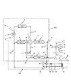
- FIG. 6 the air conditioner according to the second embodiment of the present invention will be described with reference to FIG. 6 and FIG. 7, but the same configuration as the air conditioner according to the first embodiment will be described.
- the same reference numerals are given and description thereof is omitted.
- subjected to the heat exchanger in FIG. 7 has shown the flow of heat.
- the air conditioner according to the second embodiment has a first bypass in the refrigerant pipe 11 that connects the compression cycle four-way valve 2 and the second heat source side heat exchanger 7.
- the three-way valve (bypass opening / closing means) 41 is incorporated into the refrigerant pipe 19 connecting the second utilization side heat exchanger 8 and the compression cycle four-way valve 2 to the second bypass three-way valve (bypass opening / closing means) 42. And connecting the first bypass three-way valve 41 and the second bypass three-way valve 42 with a bypass refrigerant pipe (bypass pipe) 43, that is, a flow path through which the refrigerant bypasses the compressor 1, that is, The bypass route is formed.
- the configuration in which the bypass route is provided in this way is different from that in the first embodiment.
- a natural circulation cycle TS2 using two heat source side heat exchangers 4 and 7 and two usage side heat exchangers 6 and 8 is formed.
- the operation mode No. described below can be performed.
- the operation by 5 becomes possible.
- the 1st heat source side heat exchanger 4 and the 2nd heat source side heat exchanger 7 have the almost same height position, or the 1st use side heat exchanger 6 is set.
- the first usage-side heat exchanger 6 and the second usage-side heat exchanger 8 are installed at substantially the same height as the second usage-side heat exchanger,
- the heat source side heat exchanger 4 and the second heat source side heat exchanger 7 are installed at a position higher than the first use side heat exchanger 6 and the second use side heat exchanger 8 so as to provide a head difference. I have to.
- the cycle switching four-way valve 3 is operated, the refrigerant pipe 12 and the refrigerant pipe 13 are connected, and the refrigerant pipe 16 and the refrigerant pipe 17 are connected. Further, the first bypass three-way valve 41 and the second bypass three-way valve 42 are operated to switch the refrigerant flow path so that the refrigerant flows through the bypass refrigerant pipe 43 without flowing into the compressor 1.
- Operation mode No. 5 is a cooling operation mode using only the natural circulation type cycle TS2, and the operation mode No. Similar to 4, it is used when the outside air temperature is considerably lower than the room temperature and the dehumidifying load is small (for example, when the room temperature rises due to solar radiation or internal load such as in the daytime in winter).
- the operation mode No. 5, the refrigerant circulation path is in the direction of the arrow in FIG.
- the refrigerant pipe 12 and the refrigerant pipe 13 communicate with each other and the refrigerant pipe 16 and the refrigerant pipe 17 communicate with each other by the cycle switching four-way valve 3. Further, the first bypass three-way valve 41 and the second bypass three-way valve 42 allow the refrigerant to flow through the bypass refrigerant pipe 43 without flowing into the compressor 1.
- Operation mode No. 5 the first expansion valve 5 is adjusted to a predetermined opening according to the amount of exchange heat desired to be obtained by the first use side heat exchanger 6, and the second expansion valve 9 is fully opened. .
- the operation mode No. In 5 the compressor 1 is stopped.
- the refrigerant staying in the first heat source side heat exchanger 4 and the second heat source side heat exchanger 7 dissipates heat to the atmosphere, condenses and liquefies.
- the liquid refrigerant having a high density flows toward the first usage-side heat exchanger 6 and the second usage-side heat exchanger 8 under the influence of gravity.
- the refrigerant that has flowed into the first usage-side heat exchanger 6 and the second usage-side heat exchanger 8 absorbs heat from the water circulating in the cold / hot water circulation circuit CW while flowing through the respective usage-side heat exchangers 6 and 8. Then, it evaporates and rises toward the second heat source side heat exchanger 7 due to the pressure gradient due to the density difference of the refrigerant. In this way, the refrigerant naturally circulates in the natural circulation type cycle TS2 due to the density difference.
- This operation mode No. 5 since the natural circulation type cycle TS2 can be formed by using the two heat source side heat exchangers 4 and 7 and the two usage side heat exchangers 6 and 8, the cooling capacity compared with the natural circulation type cycle TS1 described above. Will improve. Since the operation by the compressor 1 is not required, it is needless to say that the energy saving effect is high in that the power is not consumed. In addition, since the water in the cold / hot water circulation circuit CW is cooled by the 1st utilization side heat exchanger 6 and the 2nd utilization side heat exchanger 8, the air in the house 30 is cooled by the indoor heat exchanger 31. The Rukoto. That is, the operation mode No. Reference numeral 5 denotes a cooling operation mode.
- This operation mode No. 5 by operating the cycle switching four-way valve 3 to connect the refrigerant pipe 12 and the refrigerant pipe 17, and to connect the refrigerant pipe 13 and the refrigerant pipe 16, the natural circulation cycle TS 1 and the second Two natural circulation cycles of the natural circulation cycle using the heat source side heat exchanger 7 and the second utilization side heat exchanger 8 can also be formed.
- a general circulation system naturally circulation
- the cooling capacity can be ensured, or that switching to the operation mode No. 4 is facilitated according to fluctuations in the outside air temperature and the load.
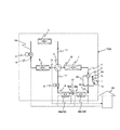
- FIGS. 8 to 14 An air conditioner according to a third embodiment of the present invention will be described with reference to FIGS. 8 to 14. The same configuration as that of the air conditioner according to the first embodiment will be described. The same reference numerals are given and the description thereof is omitted. 9 to 14, the arrows attached to the heat exchangers indicate the heat flow.
- the air conditioner according to the third embodiment uses air in the house 30 as a heat transfer medium on the use side, and uses the second use side heat exchanger 58 with the first divided heat exchanger 58a and the second heat exchanger 58.
- the divided heat exchanger 58b is divided into two, and a dehumidifying valve (third) is connected between the connecting refrigerant pipe 52a and the connecting refrigerant pipe 52b connecting the first divided heat exchanger 58a and the second divided heat exchanger 58b.
- the expansion valve) 51 is provided.
- This configuration is the main difference from the first embodiment. With this configuration, the air conditioner according to the third embodiment can be operated in the reheat dehumidifying operation mode in which the air in the house 30 is dehumidified while being warmed.
- the air in the house 30 is changed into the 1st utilization side heat exchanger 1 and the 2nd utilization side heat exchanger 58 (the 1st division
- the air conditioner according to the third embodiment is in a first state in which a natural circulation cycle TS3 and a first compression cycle PC3 described below can be used in combination. And, the refrigeration cycle can be switched by the cycle switching four-way valve 3 to the second state in which the second compression cycle PC4 can be used.
- the first heat source side heat exchanger 4 and the first expansion valve 5 are connected by a refrigerant pipe 14, and the first expansion valve 5 and the first use side heat exchanger 6 are connected to the refrigerant pipe.
- the first use side heat exchanger 6 and the cycle switching four-way valve 3 are connected by the refrigerant pipe 16
- the cycle switching four-way valve 3 and the first heat source side heat exchanger 4 are connected by the refrigerant pipe 13. It is a cycle that is connected and formed in an annular shape.
- the refrigerant circulates naturally in the natural circulation cycle TS3 due to the density difference.
- the discharge port 1b of the compressor 1 and the compression cycle four-way valve 2 are connected by a refrigerant pipe 10, and the compression cycle four-way valve 2 and the second heat source side heat exchanger 7 are connected.
- the refrigerant pipe 11 connects, the second heat source side heat exchanger 7 and the cycle switching four-way valve 3 are connected by the refrigerant pipe 12, and the cycle switching four-way valve 3 and the second expansion valve 9 are connected by the refrigerant pipe 17.
- the second expansion valve 9 and the first divided heat exchanger 58a are connected by the refrigerant pipe 18, the first divided heat exchanger 58a and the dehumidifying valve 51 are connected by the connecting refrigerant pipe 52a, and the dehumidifying valve 51 is connected.
- the second divided heat exchanger 58b are connected by a connecting refrigerant pipe 52b, the second divided heat exchanger 58b and the compression cycle four-way valve 2 are connected by a refrigerant pipe 19, and the compression cycle four-way valve 2 is connected.
- the suction port 1a of the compressor 1 are connected by a refrigerant pipe 20 and formed in an annular shape. It is a cycle. Then, the compressor 1 forcibly circulates the refrigerant in the first compression cycle PC3.
- the discharge port 1b of the compressor 1 and the compression cycle four-way valve 2 are connected by a refrigerant pipe 10, and the compression cycle four-way valve 2 and the second heat source side heat exchanger 7 are connected.
- the refrigerant pipe 11 is connected
- the second heat source side heat exchanger 7 and the cycle switching four-way valve 3 are connected by the refrigerant pipe 12
- the cycle switching four-way valve 3 and the first heat source side heat exchanger 4 are connected to the refrigerant pipe.
- the first heat source side heat exchanger 4 and the first expansion valve 5 are connected by a refrigerant pipe 14
- the first expansion valve 5 and the first use side heat exchanger 6 are connected by a refrigerant pipe 15.
- the first use side heat exchanger 6 and the cycle switching four-way valve 3 are connected by the refrigerant pipe 16
- the cycle switching four-way valve 3 and the second expansion valve 9 are connected by the refrigerant pipe 17, and the second
- the expansion valve 9 and the first divided heat exchanger 58a are connected by the refrigerant pipe 18, and the first divided heat exchanger 58a and the dehumidifying valve are connected.
- 1 is connected by a connecting refrigerant pipe 52a
- the dehumidification valve 51 and the second divided heat exchanger 58b are connected by a connecting refrigerant pipe 52b
- the second divided heat exchanger 58b and the compression cycle four-way valve 2 are connected.
- This is a cycle formed by connecting the refrigerant pipe 19 and connecting the compression cycle four-way valve 2 and the suction port 1a of the compressor 1 with the refrigerant pipe 20 in an annular shape. Then, the compressor 1 forcibly circulates the refrigerant in the second compression cycle PC4.
- Operation mode No. 6 is a reheat dehumidifying operation mode using the second compression cycle PC4 alone.
- the room temperature is higher than the set temperature, the room humidity is slightly higher than the set humidity, and heating and cooling dehumidification are required. This mode is used for load conditions.
- the refrigerant pipe 10 and the refrigerant pipe 11 are communicated with each other, and the refrigerant pipe 19 and the refrigerant pipe 20 are communicated with each other by the compression cycle four-way valve 2.
- the cycle switching four-way valve 3 allows the refrigerant pipe 12 and the refrigerant pipe 13 to communicate with each other, and the refrigerant pipe 16 and the refrigerant pipe 17 to communicate with each other.
- the second compression cycle PC4 is formed by switching the compression cycle four-way valve 2 and the cycle switching four-way valve 3 in this manner.
- the operation mode No. 6 the first expansion valve 5 and the second expansion valve 9 are fully opened, and the dehumidification valve 51 is adjusted to a predetermined opening degree.
- the high-temperature and high-pressure gas refrigerant discharged from the discharge port 1b of the compressor 1 flows through the second heat source side heat exchanger 7 and the first heat source side heat exchanger 4 in this order, it is a heat transfer medium on the heat source side. It dissipates heat to a certain atmosphere, condenses, and flows into the first usage-side heat exchanger 6 in a gas-liquid two-phase state.
- the refrigerant in the gas-liquid two-phase state is condensed by dissipating heat to the air in the house 30 that is the use-side heat transfer medium while flowing through the first use-side heat exchanger 6, and then the first While flowing through the divided heat exchanger 58a, the heat is similarly released to the air in the house 30 and further condensed and liquefied.
- the liquefied refrigerant is depressurized and expanded by the dehumidifying valve 51 to be in a gas-liquid two-phase state.
- the refrigerant in the gas-liquid two-phase state is evaporated and gasified by absorbing heat from the air in the house 30 while flowing through the second divided heat exchanger 52b.
- the gasified refrigerant flows into the suction port 1a of the compressor 1 and is compressed again by the compressor 1 to become a high-temperature and high-pressure gas refrigerant.
- Operation mode No. 7 is a reheat dehumidifying operation mode that uses the second compression cycle PC4 alone.
- the indoor temperature is higher than the set temperature
- the indoor humidity is higher than the set humidity
- the load condition requires cooling dehumidification and heating. The mode used.
- the open / closed state of the second expansion valve 9 and the dehumidifying valve 51 is the operation mode No. 6 and operation mode no. 7 and the operation mode no. 7, the first expansion valve 5 is fully open, the second expansion valve 9 is adjusted to a predetermined opening degree, and the dehumidifying valve 51 is fully open.
- the liquefied refrigerant is decompressed and expanded by the second expansion valve 9 to be in a gas-liquid two-phase state.
- the refrigerant in a gas-liquid two-phase state evaporates by absorbing heat from the air in the house 30 while flowing through the first divided heat exchanger 58a, and then passes through the second divided heat exchanger 58b. Similarly, during the flow, heat is absorbed from the air in the house 30 to further evaporate and gasify.
- the gasified refrigerant flows into the suction port 1a of the compressor 1 and is compressed again by the compressor 1 to become a high-temperature and high-pressure gas refrigerant.
- Operation mode No. 8 is a reheat dehumidifying operation mode using the second compression cycle PC4 alone.
- the indoor temperature is lower than the set temperature
- the indoor humidity is higher than the set humidity
- the load conditions require heating and cooling dehumidification.
- the refrigerant circulation path in FIG. 8 is the direction of the arrow in FIG. The route is opposite to 6.
- the refrigerant pipe 10 and the refrigerant pipe 19 communicate with each other and the refrigerant pipe 11 and the refrigerant pipe 20 communicate with each other by the compression cycle four-way valve 2.
- the cycle switching four-way valve 3 allows the refrigerant pipe 12 and the refrigerant pipe 13 to communicate with each other, and the refrigerant pipe 16 and the refrigerant pipe 17 to communicate with each other.
- the operation mode No. 8 the first expansion valve 5 and the second expansion valve 9 are fully opened, and the dehumidification valve 51 is adjusted to a predetermined opening degree.
- the high-temperature and high-pressure gas refrigerant discharged from the discharge port 1b of the compressor 1 dissipates heat and condenses to the air in the house 30 which is the heat transfer medium on the use side while flowing through the second divided heat exchanger 58b. Liquefy.
- the liquefied refrigerant is depressurized and expanded by the dehumidifying valve 51, evaporates and becomes a gas-liquid two-phase state. While the refrigerant in the gas-liquid two-phase state flows through the first divided heat exchanger 58a, the refrigerant absorbs heat from the air in the house 30 and evaporates, and then flows through the first usage-side heat exchanger 6. Similarly, it absorbs heat from the air in the house 30 and further evaporates.
- the refrigerant in the gas-liquid two-phase state that has exited the first use-side heat exchanger 6 flows through the first heat source-side heat exchanger 4 and the second heat source-side heat exchanger 7 while carrying the heat on the heat source side. It absorbs heat from the atmosphere of the medium and evaporates to gasify.
- the gasified refrigerant flows into the suction port 1a of the compressor 1 and is compressed again by the compressor 1 to become a high-temperature and high-pressure gas refrigerant.
- Operation mode No. 9 is a reheat dehumidifying operation mode that uses the second compression cycle PC4 alone.
- the room temperature is lower than the set temperature, the room humidity is slightly higher than the set humidity, and heating and some dehumidification are required. This mode is used for load conditions.
- This operation mode No. 9 is a reheat dehumidifying operation mode that uses the second compression cycle PC4 alone.
- the room temperature is lower than the set temperature, the room humidity is slightly higher than the set humidity, and heating and some dehumidification are required. This mode is used for load conditions.
- the refrigerant pipe 10 and the refrigerant pipe 19 communicate with each other and the refrigerant pipe 11 and the refrigerant pipe 20 communicate with each other by the compression cycle four-way valve 2.
- the cycle switching four-way valve 3 allows the refrigerant pipe 12 and the refrigerant pipe 13 to communicate with each other, and the refrigerant pipe 16 and the refrigerant pipe 17 to communicate with each other.
- the operation mode No. 9 the first expansion valve 5 is fully open, the second expansion valve 9 is adjusted to a predetermined opening degree, and the dehumidification valve 51 is fully open.
- the high-temperature and high-pressure gas refrigerant discharged from the discharge port 1b of the compressor 1 dissipates heat and condenses to the air in the house 30 which is the heat transfer medium on the use side while flowing through the second divided heat exchanger 58b. Subsequently, while flowing through the first divided heat exchanger 58a, the heat is similarly released to the air in the house 30 to be condensed and liquefied.
- the liquefied refrigerant is depressurized and expanded by the second expansion valve 9 and evaporated to be in a gas-liquid two-phase state.
- the refrigerant in the gas-liquid two-phase state absorbs heat from the air in the house 30 and further evaporates while flowing through the first usage-side heat exchanger 6.
- the refrigerant in the gas-liquid two-phase state that has exited the first use-side heat exchanger 6 flows through the first heat source-side heat exchanger 4 and the second heat source-side heat exchanger 7 while carrying the heat on the heat source side. It absorbs heat from the atmosphere of the medium and evaporates to gasify.
- the gasified refrigerant flows into the suction port 1a of the compressor 1 and is compressed again by the compressor 1 to become a high-temperature and high-pressure gas refrigerant.
- Operation mode No. 10 is a reheat dehumidifying operation mode using both the natural circulation type cycle TS3 and the first compression type cycle PC3. Since the room temperature is slightly higher than the set temperature and the room humidity is higher than the set humidity, cooling dehumidification and heating are performed. Is a mode used when the outside air temperature is considerably lower than the room temperature.
- This operation mode No. 10 the refrigerant circulation path is in the direction of the arrow in FIG.
- the refrigerant pipe 10 and the refrigerant pipe 11 are communicated with each other, and the refrigerant pipe 19 and the refrigerant pipe 20 are communicated with each other by the compression cycle four-way valve 2.
- the cycle switching four-way valve 3 allows the refrigerant pipe 12 and the refrigerant pipe 17 to communicate with each other, and the refrigerant pipe 13 and the refrigerant pipe 16 to communicate with each other.
- the operation mode No. 10 the first expansion valve 5 is adjusted to a predetermined opening according to the amount of exchange heat desired to be obtained by the first use side heat exchanger 6, and the second expansion valve 9 is fully open.
- the dehumidifying valve 51 is adjusted to a predetermined opening degree.
- the high-temperature and high-pressure gas refrigerant discharged from the discharge port 1b of the compressor 1 is a heat transfer medium on the heat source side while flowing through the second heat source side heat exchanger 7. It dissipates heat to a certain atmosphere, condenses, and flows into the first divided heat exchanger 58a in a gas-liquid two-phase state.
- the refrigerant in the gas-liquid two-phase state is condensed and liquefied by dissipating heat to the air in the house 30 that is the heat transfer medium on the use side while flowing through the first split-side heat exchanger 58a.
- the liquefied refrigerant is depressurized and expanded by the dehumidifying valve 51 to be in a gas-liquid two-phase state.
- the refrigerant in the gas-liquid two-phase state is evaporated and gasified by absorbing heat from the air in the house 30 while flowing through the second divided heat exchanger 52b.
- the gasified refrigerant flows into the suction port 1a of the compressor 1 and is compressed again by the compressor 1 to become a high-temperature and high-pressure gas refrigerant.
- the refrigerant staying in the first heat source side heat exchanger 4 dissipates heat to the atmosphere and condenses and liquefies.
- the liquid refrigerant having a high density descends under the influence of gravity, passes through the first expansion valve 5, absorbs heat from the air in the house 30 while flowing through the first use side heat exchanger 6, and evaporates. To do.
- the evaporated refrigerant flows toward the first heat source side heat exchanger 4.
- This operation mode No. 10 the air in the house 30 is cooled by the first use side heat exchanger 6, reheated by the first divided heat exchanger 58a, and cooled and dehumidified by the second divided heat exchanger 58b. . Therefore, even when the outside air temperature is equal to or lower than the room temperature of the house 30 and the difference between the outside air temperature and the room temperature is small, by using the natural circulation cycle TS3 and the first compression cycle PC3 in combination. Thus, appropriate cooling and dehumidification and heating can be performed, and a desired temperature and humidity environment can be obtained. Therefore, the dehumidifying capacity can be increased as compared with the natural circulation cycle.
- Operation mode No. 11 is a reheat dehumidifying operation mode using both the natural circulation cycle TS3 and the first compression cycle PC3. Although the room temperature is lower than the set temperature, the room humidity is higher than the set humidity. This is a mode that is used when the load conditions are necessary and the outside air temperature is considerably lower than the room temperature. This operation mode No.
- the refrigerant pipe 10 and the refrigerant pipe 19 communicate with each other and the refrigerant pipe 11 and the refrigerant pipe 20 communicate with each other by the compression cycle four-way valve 2.
- the cycle switching four-way valve 3 allows the refrigerant pipe 12 and the refrigerant pipe 17 to communicate with each other, and the refrigerant pipe 13 and the refrigerant pipe 16 to communicate with each other.
- the operation mode No. 11 the first expansion valve 5 is adjusted to a predetermined opening according to the amount of exchange heat desired to be obtained by the first use side heat exchanger 6, and the second expansion valve 9 is fully open.
- the dehumidifying valve 51 is adjusted to a predetermined opening degree.
- the high-temperature and high-pressure gas refrigerant discharged from the discharge port 1b of the compressor 1 is a heat transfer medium on the use side while flowing through the second divided heat exchanger 58b. It dissipates heat to the air in the house 30 and condenses and liquefies.
- the liquefied refrigerant is depressurized and expanded by the dehumidifying valve 51 to be in a gas-liquid two-phase state. While the refrigerant in the gas-liquid two-phase state flows through the first split heat exchanger 58a, the refrigerant absorbs heat from the air in the house 30 and evaporates.
- the second heat source side heat exchanger 7 While flowing through the second heat source side heat exchanger 7, It evaporates and gasifies by absorbing heat from the atmosphere, which is a heat transfer medium on the heat source side.
- the gasified refrigerant flows into the suction port 1a of the compressor 1 and is compressed again by the compressor 1 to become a high-temperature and high-pressure gas refrigerant.
- the refrigerant staying in the first heat source side heat exchanger 4 dissipates heat to the atmosphere and condenses and liquefies.
- the liquid refrigerant having a high density descends under the influence of gravity, passes through the first expansion valve 5, absorbs heat from the air in the house 30 while flowing through the first use side heat exchanger 6, and evaporates. To do.
- the evaporated refrigerant flows toward the first heat source side heat exchanger 4.
- This operation mode No. 11 the air in the house 30 is cooled by the first use side heat exchanger 6, cooled and dehumidified by the first divided heat exchanger 58a, and reheated by the second divided heat exchanger 58b. . Therefore, by using the natural circulation cycle TS3 and the first compression cycle PC3 in combination even when the outside air temperature is equal to or lower than the indoor temperature of the house 30, especially when the difference between the outside air temperature and the indoor temperature is small. Thus, appropriate cooling and dehumidification and heating can be performed, and a desired temperature and humidity environment can be obtained. Therefore, the dehumidifying capacity can be increased as compared with the natural circulation cycle.
- the operation mode No. 10 no. It goes without saying that when the compressor 1 is stopped at 11, the operation using only the natural circulation cycle TS3 can be performed.
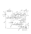
- the air conditioner according to the fourth embodiment forms an intermediate hot water circulation circuit (heat source side heat transfer medium circulation circuit) MW including the second heat source side heat exchanger 7, and the inside of the intermediate hot water circulation circuit MW 3 is characterized in that water is circulated as a heat transfer medium on the heat source side.
- intermediate hot water circulation circuit heat source side heat transfer medium circulation circuit
- the intermediate hot water circulation circuit MW is an annular circuit formed by connecting the second heat source side heat exchanger 7 and the heat storage tank 61 with intermediate hot water pipes (heat source side heat transfer medium pipes) 62 and 63.
- the water is forcibly circulated in the intermediate hot water circulation circuit MW by a circulation pump (not shown).
- the heat storage tank 61 is filled with a heat storage material.
- the operation mode No. described above is used. 1 and no. 3, the temperature of the refrigerant is released to the outside by the second heat source side heat exchanger 7, and the water flowing in the intermediate hot water circulation circuit MW is heated from the second heat source side heat exchanger 7. Absorb. The hot heat absorbed by the water is stored in the heat storage tank 61, and the water circulating in the intermediate hot water circulation circuit MW becomes intermediate hot water.
- the intermediate hot water can be made by effectively utilizing the exhaust heat of the second heat source side heat exchanger 7.
- the second heat source side heat exchanger 7 can be used as an evaporator of a hot water supply cycle. Specifically, as shown in FIG. 15, a hot water supply compressor 71, a hot water supply condenser 72, a hot water supply expansion valve 73, and a second heat source side heat exchanger 7 are sequentially connected by hot water supply refrigerant pipes 74a to 74d. Thus, an annular hot water supply cycle is formed, and a hot water supply system for supplying hot water is constructed by connecting the hot water supply condenser 72 and the hot water storage tank 75 with hot water supply pipes 76 and 77.
- the gas-liquid two-phase hot water supply refrigerant decompressed and expanded by the hot water supply expansion valve 73 absorbs heat from the second heat source side heat exchanger 7 and evaporates to be gasified. That is, in the hot water supply cycle, the second heat source side heat exchanger 7 functions as an evaporator.
- the heat transfer medium on the heat source side that exchanges heat with the second heat source side heat exchanger 7 serves as a hot water supply refrigerant.
- the 2nd heat source side heat exchanger 7 can be utilized for both a hot-water supply system and an air-conditioning system, cost can be reduced.
- R134a, HFO1234yf, HFO1234ze, CO2, or the like may be used as the hot water supply refrigerant.
- the heat exchanger used for the natural cycle can be used as the heat exchanger for the compression cycle, so that the efficiency of heat exchange can be increased.
- the natural circulation type cycle and the compression type cycle can be used together, the dehumidifying ability is increased even when the outside air temperature is equal to or lower than the room temperature and the difference between the outside air temperature and the room temperature is small. Can do.
- the exhaust heat of the heat exchanger can be used for water supply or hot water supply equipment, so that energy can be used effectively.
- SYMBOLS 1 Compressor, 1a ... Suction port, 1b ... Discharge port, 2 ... Four-way valve for compression cycle (flow path switching valve), 3 ... Four-way valve for cycle switching (cycle switching means), 4 ... First heat source side Heat exchanger, 5 ... 1st expansion valve, 6 ... 1st user side heat exchanger, 7 ... 2nd heat source side heat exchanger, 8 ... 2nd user side heat exchanger, 9 ... 2nd Expansion valve, 10-20 ... refrigerant pipe, 30 ... house (cooled space), 31 ... indoor heat exchanger, 32 ... circulating pump, 33 ... four-way valve for cold / hot water circuit, 35-40 ...
Landscapes
- Engineering & Computer Science (AREA)
- Mechanical Engineering (AREA)
- General Engineering & Computer Science (AREA)
- Physics & Mathematics (AREA)
- Thermal Sciences (AREA)
- Life Sciences & Earth Sciences (AREA)
- Sustainable Development (AREA)
- Chemical & Material Sciences (AREA)
- Combustion & Propulsion (AREA)
- Compression-Type Refrigeration Machines With Reversible Cycles (AREA)
- Other Air-Conditioning Systems (AREA)
- Air Conditioning Control Device (AREA)
Abstract
L'invention a pour objectif de développer les capacités de refroidissement et de chauffage d'un dispositif de conditionnement d'air, par la mise en œuvre d'un échangeur thermique de cycle à circulation naturelle en tant qu'échangeur thermique de cycle à compression. Ainsi, le dispositif de conditionnement d'air de l'invention présente une configuration apte à former au moins les trois cycles de refroidissement suivants : un cycle à circulation naturelle (TS1) dans lequel sont formés de façon circulaire par connexion en série au moyen d'un tuyau de fluide frigorigène un premier échangeur thermique côté source de chaleur (4), une première vanne de détente (5), et un premier échangeur thermique côté utilisation (6); un premier cycle à compression (PC1) dans lequel sont formés de façon circulaire par connexion en série au moyen d'un tuyau de fluide frigorigène un orifice d'évacuation (1b) d'une machine à compression (1), une vanne de commutation de canal d'écoulement (2), un second échangeur thermique côté source de chaleur (7), une seconde vanne de détente (9), un second échangeur thermique côté utilisation (8), et un orifice d'aspiration (1a) de la machine à compression; et un second cycle à compression (PC2) dans lequel sont formés de façon circulaire par connexion en série au moyen d'un tuyau de fluide frigorigène l'orifice d'évacuation (1b) de la machine à compression, la vanne de commutation de canal d'écoulement (2), le second échangeur thermique côté source de chaleur (7), le premier échangeur thermique côté source de chaleur (4), la première vanne de détente (5), le premier échangeur thermique côté utilisation (6), le second échangeur thermique côté utilisation (8), et l'orifice d'aspiration (1a) de la machine à compression.
Priority Applications (4)
| Application Number | Priority Date | Filing Date | Title |
|---|---|---|---|
| JP2012501571A JP5373959B2 (ja) | 2010-02-24 | 2010-02-24 | 空気調和装置 |
| EP10846499A EP2541168A1 (fr) | 2010-02-24 | 2010-02-24 | Dispositif de conditionnement d'air |
| CN201080063497.1A CN102753915B (zh) | 2010-02-24 | 2010-02-24 | 空调装置 |
| PCT/JP2010/052892 WO2011104834A1 (fr) | 2010-02-24 | 2010-02-24 | Dispositif de conditionnement d'air |
Applications Claiming Priority (1)
| Application Number | Priority Date | Filing Date | Title |
|---|---|---|---|
| PCT/JP2010/052892 WO2011104834A1 (fr) | 2010-02-24 | 2010-02-24 | Dispositif de conditionnement d'air |
Publications (1)
| Publication Number | Publication Date |
|---|---|
| WO2011104834A1 true WO2011104834A1 (fr) | 2011-09-01 |
Family
ID=44506281
Family Applications (1)
| Application Number | Title | Priority Date | Filing Date |
|---|---|---|---|
| PCT/JP2010/052892 WO2011104834A1 (fr) | 2010-02-24 | 2010-02-24 | Dispositif de conditionnement d'air |
Country Status (4)
| Country | Link |
|---|---|
| EP (1) | EP2541168A1 (fr) |
| JP (1) | JP5373959B2 (fr) |
| CN (1) | CN102753915B (fr) |
| WO (1) | WO2011104834A1 (fr) |
Cited By (4)
| Publication number | Priority date | Publication date | Assignee | Title |
|---|---|---|---|---|
| WO2013080297A1 (fr) * | 2011-11-29 | 2013-06-06 | 株式会社日立製作所 | Système de climatisation et d'approvisionnement d'eau chaude |
| CN106940099A (zh) * | 2016-01-05 | 2017-07-11 | 青岛海尔新能源电器有限公司 | 热泵热水器 |
| CN110425776A (zh) * | 2019-08-19 | 2019-11-08 | 北京丰联奥睿科技有限公司 | 一种v型竖管蒸发式冷却塔及其双控制空调系统 |
| JP2021096043A (ja) * | 2019-12-18 | 2021-06-24 | 株式会社日立産機システム | 排熱回収システム、及び、それに用いる気体圧縮機 |
Families Citing this family (1)
| Publication number | Priority date | Publication date | Assignee | Title |
|---|---|---|---|---|
| WO2021044547A1 (fr) * | 2019-09-04 | 2021-03-11 | ダイキン工業株式会社 | Unité de compresseur et dispositif de réfrigération |
Citations (4)
| Publication number | Priority date | Publication date | Assignee | Title |
|---|---|---|---|---|
| JPH10300128A (ja) | 1997-04-23 | 1998-11-13 | Matsushita Electric Works Ltd | 冷媒自然循環冷却除湿装置およびこの装置を併設した空気調和装置 |
| JP2000074515A (ja) * | 1998-08-31 | 2000-03-14 | Mitsubishi Electric Building Techno Service Co Ltd | 空調装置 |
| JP2000111190A (ja) * | 1998-10-09 | 2000-04-18 | Mitsubishi Electric Building Techno Service Co Ltd | 冷房装置 |
| JP2003121072A (ja) | 2001-10-09 | 2003-04-23 | Mitsubishi Electric Corp | 除湿乾燥装置 |
Family Cites Families (2)
| Publication number | Priority date | Publication date | Assignee | Title |
|---|---|---|---|---|
| EP1164338B1 (fr) * | 1999-02-24 | 2006-01-11 | Hachiyo Engineering Co., Ltd. | Systeme de pompe a chaleur combinant un cycle ammoniac avec un cycle dioxyde de carbone |
| JPWO2009087733A1 (ja) * | 2008-01-07 | 2011-05-19 | 三菱電機株式会社 | 冷凍サイクル装置および四方弁 |
-
2010
- 2010-02-24 WO PCT/JP2010/052892 patent/WO2011104834A1/fr active Application Filing
- 2010-02-24 EP EP10846499A patent/EP2541168A1/fr not_active Withdrawn
- 2010-02-24 CN CN201080063497.1A patent/CN102753915B/zh not_active Expired - Fee Related
- 2010-02-24 JP JP2012501571A patent/JP5373959B2/ja not_active Expired - Fee Related
Patent Citations (4)
| Publication number | Priority date | Publication date | Assignee | Title |
|---|---|---|---|---|
| JPH10300128A (ja) | 1997-04-23 | 1998-11-13 | Matsushita Electric Works Ltd | 冷媒自然循環冷却除湿装置およびこの装置を併設した空気調和装置 |
| JP2000074515A (ja) * | 1998-08-31 | 2000-03-14 | Mitsubishi Electric Building Techno Service Co Ltd | 空調装置 |
| JP2000111190A (ja) * | 1998-10-09 | 2000-04-18 | Mitsubishi Electric Building Techno Service Co Ltd | 冷房装置 |
| JP2003121072A (ja) | 2001-10-09 | 2003-04-23 | Mitsubishi Electric Corp | 除湿乾燥装置 |
Cited By (7)
| Publication number | Priority date | Publication date | Assignee | Title |
|---|---|---|---|---|
| WO2013080297A1 (fr) * | 2011-11-29 | 2013-06-06 | 株式会社日立製作所 | Système de climatisation et d'approvisionnement d'eau chaude |
| JPWO2013080297A1 (ja) * | 2011-11-29 | 2015-04-27 | 株式会社日立製作所 | 空調給湯システム |
| CN106940099A (zh) * | 2016-01-05 | 2017-07-11 | 青岛海尔新能源电器有限公司 | 热泵热水器 |
| CN106940099B (zh) * | 2016-01-05 | 2023-09-12 | 青岛海尔新能源电器有限公司 | 热泵热水器 |
| CN110425776A (zh) * | 2019-08-19 | 2019-11-08 | 北京丰联奥睿科技有限公司 | 一种v型竖管蒸发式冷却塔及其双控制空调系统 |
| JP2021096043A (ja) * | 2019-12-18 | 2021-06-24 | 株式会社日立産機システム | 排熱回収システム、及び、それに用いる気体圧縮機 |
| JP7309593B2 (ja) | 2019-12-18 | 2023-07-18 | 株式会社日立産機システム | 排熱回収システム、及び、それに用いる気体圧縮機 |
Also Published As
| Publication number | Publication date |
|---|---|
| CN102753915B (zh) | 2014-11-05 |
| JPWO2011104834A1 (ja) | 2013-06-17 |
| JP5373959B2 (ja) | 2013-12-18 |
| CN102753915A (zh) | 2012-10-24 |
| EP2541168A1 (fr) | 2013-01-02 |
Similar Documents
| Publication | Publication Date | Title |
|---|---|---|
| JP5297968B2 (ja) | 空気調和装置 | |
| US8001802B2 (en) | Air conditioner | |
| JP6095764B2 (ja) | 空気調和装置 | |
| WO2012070192A1 (fr) | Climatiseur | |
| WO2012077166A1 (fr) | Climatiseur | |
| JP5373964B2 (ja) | 空調給湯システム | |
| JP5395950B2 (ja) | 空気調和装置および空調給湯システム | |
| JP5595521B2 (ja) | ヒートポンプ装置 | |
| JP5490245B2 (ja) | 空気調和装置 | |
| JP2006292313A (ja) | 地中熱利用装置 | |
| JP5335131B2 (ja) | 空調給湯システム | |
| JP2011069529A (ja) | 空調給湯システム及びヒートポンプユニット | |
| WO2014083681A1 (fr) | Dispositif de climatisation | |
| JP5373959B2 (ja) | 空気調和装置 | |
| CN210951942U (zh) | 热管理系统 | |
| WO2011099067A1 (fr) | Dispositif à cycle frigorifique | |
| JP6781560B2 (ja) | 換気装置 | |
| CN113654259B (zh) | 制冷系统和制冷设备 | |
| JP2013113499A (ja) | 空気調和機 | |
| JP2000234771A (ja) | 二次冷媒蓄熱空調システム | |
| JP2007147133A (ja) | 空気調和装置 | |
| CN112577213A (zh) | 热管理系统 | |
| WO2015079531A1 (fr) | Climatiseur |
Legal Events
| Date | Code | Title | Description |
|---|---|---|---|
| WWE | Wipo information: entry into national phase |
Ref document number: 201080063497.1 Country of ref document: CN |
|
| 121 | Ep: the epo has been informed by wipo that ep was designated in this application |
Ref document number: 10846499 Country of ref document: EP Kind code of ref document: A1 |
|
| WWE | Wipo information: entry into national phase |
Ref document number: 2012501571 Country of ref document: JP |
|
| WWE | Wipo information: entry into national phase |
Ref document number: 2010846499 Country of ref document: EP |
|
| NENP | Non-entry into the national phase |
Ref country code: DE |