WO2011104834A1 - Air conditioner - Google Patents
Air conditioner Download PDFInfo
- Publication number
- WO2011104834A1 WO2011104834A1 PCT/JP2010/052892 JP2010052892W WO2011104834A1 WO 2011104834 A1 WO2011104834 A1 WO 2011104834A1 JP 2010052892 W JP2010052892 W JP 2010052892W WO 2011104834 A1 WO2011104834 A1 WO 2011104834A1
- Authority
- WO
- WIPO (PCT)
- Prior art keywords
- heat exchanger
- refrigerant
- side heat
- cycle
- compressor
- Prior art date
Links
Images


Classifications
-
- F—MECHANICAL ENGINEERING; LIGHTING; HEATING; WEAPONS; BLASTING
- F24—HEATING; RANGES; VENTILATING
- F24F—AIR-CONDITIONING; AIR-HUMIDIFICATION; VENTILATION; USE OF AIR CURRENTS FOR SCREENING
- F24F5/00—Air-conditioning systems or apparatus not covered by F24F1/00 or F24F3/00, e.g. using solar heat or combined with household units such as an oven or water heater
- F24F5/0003—Exclusively-fluid systems
-
- F—MECHANICAL ENGINEERING; LIGHTING; HEATING; WEAPONS; BLASTING
- F25—REFRIGERATION OR COOLING; COMBINED HEATING AND REFRIGERATION SYSTEMS; HEAT PUMP SYSTEMS; MANUFACTURE OR STORAGE OF ICE; LIQUEFACTION SOLIDIFICATION OF GASES
- F25B—REFRIGERATION MACHINES, PLANTS OR SYSTEMS; COMBINED HEATING AND REFRIGERATION SYSTEMS; HEAT PUMP SYSTEMS
- F25B13/00—Compression machines, plants or systems, with reversible cycle
-
- F—MECHANICAL ENGINEERING; LIGHTING; HEATING; WEAPONS; BLASTING
- F25—REFRIGERATION OR COOLING; COMBINED HEATING AND REFRIGERATION SYSTEMS; HEAT PUMP SYSTEMS; MANUFACTURE OR STORAGE OF ICE; LIQUEFACTION SOLIDIFICATION OF GASES
- F25B—REFRIGERATION MACHINES, PLANTS OR SYSTEMS; COMBINED HEATING AND REFRIGERATION SYSTEMS; HEAT PUMP SYSTEMS
- F25B25/00—Machines, plants or systems, using a combination of modes of operation covered by two or more of the groups F25B1/00 - F25B23/00
- F25B25/005—Machines, plants or systems, using a combination of modes of operation covered by two or more of the groups F25B1/00 - F25B23/00 using primary and secondary systems
-
- F—MECHANICAL ENGINEERING; LIGHTING; HEATING; WEAPONS; BLASTING
- F25—REFRIGERATION OR COOLING; COMBINED HEATING AND REFRIGERATION SYSTEMS; HEAT PUMP SYSTEMS; MANUFACTURE OR STORAGE OF ICE; LIQUEFACTION SOLIDIFICATION OF GASES
- F25B—REFRIGERATION MACHINES, PLANTS OR SYSTEMS; COMBINED HEATING AND REFRIGERATION SYSTEMS; HEAT PUMP SYSTEMS
- F25B41/00—Fluid-circulation arrangements
-
- F—MECHANICAL ENGINEERING; LIGHTING; HEATING; WEAPONS; BLASTING
- F25—REFRIGERATION OR COOLING; COMBINED HEATING AND REFRIGERATION SYSTEMS; HEAT PUMP SYSTEMS; MANUFACTURE OR STORAGE OF ICE; LIQUEFACTION SOLIDIFICATION OF GASES
- F25B—REFRIGERATION MACHINES, PLANTS OR SYSTEMS; COMBINED HEATING AND REFRIGERATION SYSTEMS; HEAT PUMP SYSTEMS
- F25B2313/00—Compression machines, plants or systems with reversible cycle not otherwise provided for
- F25B2313/027—Compression machines, plants or systems with reversible cycle not otherwise provided for characterised by the reversing means
- F25B2313/02742—Compression machines, plants or systems with reversible cycle not otherwise provided for characterised by the reversing means using two four-way valves
Definitions
- the present invention relates to an air conditioner installed in, for example, a house or an office building, and in particular, includes a natural circulation cycle in which refrigerant naturally circulates due to a density difference and a compression cycle in which refrigerant is forced to circulate by a compressor.
- the present invention relates to an air conditioner that can be used side by side and can selectively use these two refrigeration cycles.
- Patent Document 1 discloses a compressor, a reheat condenser, and a cooler for cooling the air in the box.
- Refrigeration cycle compression cycle
- natural circulation cooling condenser natural circulation cooling system
- condensers for natural circulation cooling and natural circulation cooling coolers natural And a cycle-type cycle
- Patent Document 2 discloses a natural refrigerant cooling system including an indoor heat exchanger, an outdoor heat exchanger, a refrigerant pipe, an expansion valve, and a refrigerant compression forced circulation device corresponding to a compression refrigerator of another device.
- a dehumidifying device is disclosed.
- This natural circulation cooling dehumidification device is a natural circulation cycle formed by connecting an outdoor heat exchanger, an indoor heat exchanger at a position lower than the outdoor heat exchanger, and an expansion valve in an annular shape with refrigerant piping. And a compression cycle using a refrigerant compression forced circulation device, and an evaporative heat exchanger of the compression cycle is tightly coupled to an outdoor heat exchanger of the natural circulation cycle.
- the evaporative heat exchanger can efficiently take heat from the outdoor heat exchanger, even when the temperature difference between the indoor and the outdoor is eliminated and the cooling and dehumidifying capacity is reduced.
- the refrigerant compression forced circulation device it is possible to compensate for a decrease in the cooling and dehumidifying capability of the refrigerant natural circulation cooling and dehumidifying device.
- Patent Document 2 a refrigerant natural circulation cooling and dehumidifying device (natural circulation type cycle) using refrigerant natural circulation is added to a refrigerant compression forced circulation cooling / heating device (compression type cycle) using a refrigerant compression forced circulation system.
- An air conditioning apparatus is disclosed. According to this air conditioner, it is possible to perform a high-quality dry operation mode in which heating is performed by the refrigerant compression forced circulation cooling / heating dual-purpose device while dehumidification is performed by the refrigerant natural circulation cooling / dehumidifying device, thereby improving comfort. it can.
- JP 2003-121072 A Japanese Patent Laid-Open No. 10-300128
- the natural circulation cycle and the compression cycle constitute an independent refrigeration cycle. Therefore, the heat exchanger of the natural circulation cycle is connected to the compression cycle at the peak of air conditioning. It was impossible to use as a heat exchanger. Therefore, the subject that the heat exchange function of the heat exchanger of a natural circulation type cycle was not utilized effectively occurred.
- the natural circulation type cycle is a cycle in which a head difference is provided between two heat exchangers, and the refrigerant naturally circulates due to a density difference.
- the difference between the room temperature and the room temperature is small, there is a problem that the dehumidifying ability cannot be obtained even if the cooling operation using the natural circulation type cycle is performed.
- the present invention has been made in view of the above-described circumstances, and an object of the present invention is to provide a natural circulation cycle heat exchanger for a compression cycle in an air conditioner provided with a compression cycle and a natural circulation cycle. It is to be used as a heat exchanger to exhibit air conditioning capability.
- the present invention also provides an air conditioning system that can enhance the dehumidification capability even when the difference between the outside air temperature and the room temperature is small by using both the natural circulation cycle and the compression cycle when the outside air temperature is equal to or lower than the room temperature. It is also an object to provide an apparatus.
- an air conditioner of the present invention includes a compressor, first and second heat source side heat exchangers that exchange heat between the heat transfer medium on the heat source side and the refrigerant, and heat on the use side.
- An air conditioner including first and second usage-side heat exchangers that exchange heat between the transport medium and the refrigerant, a flow path switching valve that switches a flow path direction of the refrigerant, and first and second expansion valves
- the first heat source side heat exchanger, the first expansion valve, and the first heat source side heat exchanger installed at a position lower than the first heat source side heat exchanger are sequentially refrigerant.
- a natural circulation cycle that is formed in an annular shape by connecting with piping, and the refrigerant circulates naturally due to a density difference, a discharge port of the compressor, the flow path switching valve, the second heat source side heat exchanger, the second The expansion valve, the second user-side heat exchanger, and the suction port of the compressor are sequentially connected by refrigerant piping.
- a first compression cycle in which the refrigerant is forcedly circulated by the compressor, a discharge port of the compressor, the flow path switching valve, the second heat source side heat exchanger, the first The heat source side heat exchanger, the first expansion valve, the first usage side heat exchanger, the second usage side heat exchanger, and the compressor suction port are sequentially connected by a refrigerant pipe to form an annular shape.
- Cycle switching means for switching the refrigeration cycle between the first state to be formed and the second state in which the second compression cycle is formed is provided.
- the heat exchanger of the natural circulation cycle can be used as the heat exchanger of the second compression cycle.
- a large effect is exhibited at the peak of air conditioning.
- this invention is a pipe
- the use side heat transfer medium circulation circuit is provided, and the air in the space to be cooled is cooled and heated via the indoor heat exchanger installed in the space to be cooled.
- Refrigerant piping connecting the indoor unit and the outdoor unit is not necessary, and the amount of refrigerant is small.
- the outdoor unit when a natural circulation cycle is formed in a conventional configuration in which an indoor unit and an outdoor unit are connected by a refrigerant pipe, the outdoor unit must be installed at a higher position than the indoor unit, and layout restrictions are imposed. was there.
- the use side heat transfer medium circulation circuit is provided, there is an advantage that the degree of freedom in layout increases.
- this invention divides the said 2nd utilization side heat exchanger into the 1st division
- the reheat dehumidifying operation for dehumidifying the air in the space to be cooled can be performed by the first divided heat exchanger, the second divided heat exchanger, and the third expansion valve.
- the dehumidifying capacity can be increased even when the outside air temperature is equal to or lower than the room temperature and the difference between the outside temperature and the room temperature is small. it can.
- the present invention is the above configuration, wherein the second heat source side heat exchanger and the heat storage tank are connected by a heat source side heat transfer medium pipe to form an annular heat source side heat transfer medium circulation circuit, and the heat source side
- the heat transfer medium circulation circuit is characterized in that water as the heat transfer medium on the heat source side is forcibly circulated.
- the intermediate hot water can be made using the exhaust heat of the heat source side heat exchanger, the efficiency is improved by using this intermediate hot water for hot water supply or the like. Furthermore, in the present invention, since the exhaust heat of the heat source side heat exchanger can be stored by the heat storage tank, for example, it is possible to eliminate the difference between the time zones of the air conditioning load and the hot water supply load.
- the hot water supply compressor, the hot water use side heat exchanger, the hot water supply expansion valve, and the second heat source side heat exchanger are sequentially connected by the hot water supply refrigerant pipe.
- An annular hot water supply cycle is formed, and hot water supply refrigerant as a heat transfer medium on the heat source side is forcibly circulated by the hot water supply compressor in the hot water supply cycle.
- hot water having a temperature higher than that of the intermediate hot water can be generated.
- the present invention provides a bypass pipe that bypasses the suction port and the discharge port of the compressor, a refrigerant flow path, a flow path that passes through the compressor, and a flow path that passes through the bypass pipe. And a bypass opening / closing means for switching between the flow paths.
- a natural circulation cycle using two heat source side heat exchangers and two utilization side heat exchangers can be formed, it is possible to operate with a natural circulation cycle with high heat exchange efficiency, and to save energy. Can be planned.
- the heat exchanger of the natural circulation type cycle can be used as the heat exchanger of the compression type cycle, so that the heat transfer area of the heat exchanger is larger than that using only the heat exchanger of the compression type cycle. Becomes wider, heat exchange efficiency is improved, and energy can be saved.
- the natural circulation cycle and the compression cycle can be used in combination, the dehumidifying ability can be increased even when the outside air temperature is equal to or lower than the room temperature and the temperature difference between the outside temperature and the room temperature is small.
- FIG. 6 is an operation diagram showing the flow of the refrigerant and the heat transfer medium in FIG.
- the operation mode No. of the air conditioner according to the first embodiment of the present invention is described.
- 3 is an operation diagram showing the flow of the refrigerant and the heat transfer medium in FIG. The operation mode No. of the air conditioner according to the first embodiment of the present invention is described.
- 6 is an operation diagram showing the flow of the refrigerant and the heat transfer medium in FIG. It is a basic block diagram showing each component which comprises the air conditioning apparatus which concerns on the 2nd Example of this invention, and those connection relations.
- the operation mode No. of the air conditioner according to the second embodiment of the present invention is described.
- 6 is an operation diagram showing the flow of the refrigerant and the heat transfer medium in FIG. It is a basic block diagram showing each component which comprises the air conditioning apparatus which concerns on the 3rd Example of this invention, and those connection relations.
- the operation mode No. of the air conditioner according to the third embodiment of the present invention is described.
- 6 is an operation diagram showing the flow of the refrigerant and the heat transfer medium in FIG.
- FIG. 7 is an operation diagram showing the flow of the refrigerant and the heat transfer medium in FIG.
- the operation mode No. of the air conditioner according to the third embodiment of the present invention is described.
- 8 is an operation diagram showing the flow of the refrigerant and the heat transfer medium in FIG.
- the operation mode No. of the air conditioner according to the third embodiment of the present invention is described.
- 9 is an operation diagram showing the flow of the refrigerant and the heat transfer medium in FIG.
- the operation mode No. of the air conditioner according to the third embodiment of the present invention is described.
- 10 is an operation diagram showing the flow of the refrigerant and the heat transfer medium in FIG.
- the operation mode No. of the air conditioner according to the third embodiment of the present invention is described.
- 11 is an operation diagram showing the flow of the refrigerant and the heat transfer medium in FIG. It is a basic block diagram showing each component which comprises the air conditioning apparatus which concerns on the 4th Example of this invention, and those connection relations.
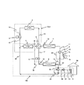
- FIG. 1 is a variable capacity compressor for refrigerant
- 2 is a four-way valve for compression cycle (flow path switching valve)
- 3 is a four-way valve for cycle switching (cycle switching means)
- 4 is the atmosphere (heat source side)
- First heat source side heat exchanger that exchanges heat between the refrigerant and the refrigerant
- 5 is a first expansion valve
- 6 is a first that exchanges heat between the water (the heat carrier medium on the use side) and the refrigerant.
- a heat exchanger on the use side, 7 is a second heat source side heat exchanger that exchanges heat between the atmosphere (heat transfer medium on the heat source side) and the refrigerant
- 8 is a heat exchange between water (heat transfer medium on the use side) and the refrigerant.
- the 2nd utilization side heat exchanger to be made to represent, 9 represents the 2nd expansion valve, respectively.
- the first use side heat exchanger 6 is installed at a position lower than the first heat source side heat exchanger 4. That is, a head difference is provided between the first use side heat exchanger 6 and the first heat source side heat exchanger 4.
- R410A is used as the refrigerant.
- the first heat source side heat exchanger 4 and the first expansion valve 5 are connected by a refrigerant pipe 14, and the first expansion valve 5 and the first usage side heat exchanger 6 are connected to the refrigerant pipe.
- the first use side heat exchanger 6 and the cycle switching four-way valve 3 are connected by the refrigerant pipe 16
- the cycle switching four-way valve 3 and the first heat source side heat exchanger 4 are connected by the refrigerant pipe 13. It is a refrigeration cycle that is connected and formed in an annular shape. The refrigerant naturally circulates in the natural circulation cycle due to the density difference.
- the discharge port 1b of the compressor 1 and the compression cycle four-way valve 2 are connected by a refrigerant pipe 10, and the compression cycle four-way valve 2 and the second heat source side heat exchanger 7 are connected.
- the refrigerant pipe 11 connects, the second heat source side heat exchanger 7 and the cycle switching four-way valve 3 are connected by the refrigerant pipe 12, and the cycle switching four-way valve 3 and the second expansion valve 9 are connected by the refrigerant pipe 17.
- the second expansion valve 9 and the second use side heat exchanger 8 are connected by the refrigerant pipe 18, and the second use side heat exchanger 8 and the compression cycle four-way valve 2 are connected by the refrigerant pipe 19.
- the discharge port 1b of the compressor 1 and the compression cycle four-way valve 2 are connected by a refrigerant pipe 10, and the compression cycle four-way valve 2 and the second heat source side heat exchanger 7 are connected.
- the refrigerant pipe 11 is connected
- the second heat source side heat exchanger 7 and the cycle switching four-way valve 3 are connected by the refrigerant pipe 12
- the cycle switching four-way valve 3 and the first heat source side heat exchanger 4 are connected to the refrigerant pipe.
- the first heat source side heat exchanger 4 and the first expansion valve 5 are connected by a refrigerant pipe 14
- the first expansion valve 5 and the first use side heat exchanger 6 are connected by a refrigerant pipe 15.
- the first use side heat exchanger 6 and the cycle switching four-way valve 3 are connected by the refrigerant pipe 16
- the cycle switching four-way valve 3 and the second expansion valve 9 are connected by the refrigerant pipe 17, and the second
- the expansion valve 9 and the second use side heat exchanger 8 are connected by a refrigerant pipe 18, and the second use side heat exchanger 8 and the compression type heat exchanger 8 are connected.
- Le four-way valve 2 are connected by refrigerant pipe 19
- the compression-type cycle four-way valve 2 inlet 1a of the compressor 1 is connected to a refrigeration cycle formed annularly refrigerant pipe 20. Then, the compressor 1 forcibly circulates the refrigerant in the second compression cycle PC2.
- Cycle switching among the natural circulation cycle TS1, the first compression cycle PC1 and the second compression cycle PC2 is performed by operating the cycle switching four-way valve 3. More specifically, when the cycle switching four-way valve 3 is operated so that the refrigerant pipe 13 and the refrigerant pipe 16 communicate with each other and the refrigerant pipe 12 and the refrigerant pipe 17 communicate with each other, Two independent refrigeration cycles are formed, a circulation cycle TS1 and a first compression cycle PC1. That is, two refrigeration cycles of the natural circulation type cycle TS1 and the first compression type cycle PC1 are simultaneously formed.
- the air conditioner according to the first embodiment can operate the natural circulation cycle TS1 and the first compression cycle PC1 at the same time by operating the cycle switching four-way valve 4.
- two states can be created: a state where only the second compression cycle PC2 can be used.
- Numeral 30 is a house, 31 is an indoor heat exchanger installed in the room (cooled space), 32 is a circulation pump, and 33 is a cold / hot water circuit four-way valve.
- the cold / hot water circulation circuit (use-side heat transfer medium circulation circuit) CW connects the indoor heat exchanger 31 and the circulation pump 32 with a cold / hot water pipe (use-side heat transfer medium pipe) 35, and the circulation pump 32 and the cold / hot water circuit use.
- the four-way valve 33 is connected by the cold / hot water pipe 36, the cold / hot water circuit four-way valve 33 and the second use side heat exchanger 8 are connected by the cold / hot water pipe 37, and the second use side heat exchanger 8 and the first
- the use side heat exchanger 6 is connected by a cold / hot water pipe 38, the first use side heat exchanger 6 and the cold / hot water circuit four-way valve 33 are connected by a cold / hot water pipe 39, and the cold / hot water circuit four-way valve 33 is connected.
- This is a circuit formed in an annular shape by connecting the indoor heat exchanger 31 with a cold / hot water pipe 40. Then, the circulation pump 32 forces water to circulate in the cold / hot water circulation circuit CW.
- the operation mode No. 1-No. 4 four operation modes can be performed.
- hs is an abbreviation for heat source
- app is application
- H Humidity
- Operation mode No. 1 (Fig. 2) Operation mode No.
- Reference numeral 1 denotes a cooling operation mode in which the second compression cycle PC2 is used alone, and is an operation mode used when the outside air temperature is high and the cooling load is large, such as in the daytime in summer.
- This mode is used for This operation mode No. 1, the refrigerant circulation path is in the direction of the arrow in FIG.
- the refrigerant pipe 10 and the refrigerant pipe 11 are communicated with each other, and the refrigerant pipe 19 and the refrigerant pipe 20 are communicated with each other by the compression cycle four-way valve 2.
- the cycle switching four-way valve 3 allows the refrigerant pipe 12 and the refrigerant pipe 13 to communicate with each other, and the refrigerant pipe 16 and the refrigerant pipe 17 to communicate with each other.
- the second compression cycle PC2 is formed by switching the compression cycle four-way valve 2 and the cycle switching four-way valve 3 in this manner.
- the operation mode No. 1 the first expansion valve 5 is adjusted to a predetermined opening, and the second expansion valve 9 is fully opened.
- the high-temperature and high-pressure gas refrigerant discharged from the discharge port 1b of the compressor 1 flows into the second heat source side heat exchanger 7 through the four-way valve 2 for the compression cycle, and this second heat source side heat exchanger.
- the heat is dissipated to the atmosphere while flowing through the air 7 and condensed.
- the refrigerant that has exited the second heat source side heat exchanger 7 flows into the first heat source side heat exchanger 4 through the four-way valve 3 for cycle switching, and the first heat source side heat exchanger 4 is passed through the first heat source side heat exchanger 4. While flowing, it dissipates heat to the atmosphere, condenses, and finally liquefies.
- the liquefied refrigerant is depressurized and expanded by the first expansion valve 5 adjusted to a predetermined opening degree, and flows into the first usage-side heat exchanger 6 in a low-temperature and low-pressure gas-liquid two-phase state.
- the refrigerant in the gas-liquid two-phase state evaporates by absorbing heat from the water circulating in the cold / hot water circulation circuit CW while flowing through the first use side heat exchanger 6, and further, the cycle switching four-way valve 3, the second Are sequentially passed through the expansion valve 9 and flow into the second use side heat exchanger 8.
- the refrigerant flowing into the second usage-side heat exchanger 8 evaporates by absorbing heat from the water circulating in the cold / hot water circulation circuit CW while flowing through the second usage-side heat exchanger 8, and finally To gasify.
- the gasified refrigerant passes through the compression cycle four-way valve 2 and flows into the suction port 1a of the compressor 1 and is compressed again by the compressor 1 to become a high-temperature and high-pressure gas refrigerant.
- This operation mode No. 1 the water in the cold / hot water circulation circuit CW is cooled by the first use side heat exchanger 6 and the second use side heat exchanger 8, so the air in the house 30 is cooled by the indoor heat exchanger 31. Will be. That is, the operation mode No. Reference numeral 1 denotes a cooling operation mode.
- This operation mode No. 1 the refrigerant releases heat to the atmosphere with the two heat source side heat exchangers 4 and 7, and absorbs heat from water with the two usage side heat exchangers 6 and 8. The cooling capacity can be increased by using the cooler effectively.
- Operation mode No. 2 (Fig. 3) Operation mode No.
- Reference numeral 2 denotes a heating operation mode in which the second compression cycle PC2 is used alone, and is an operation mode used at night in winter when the indoor heating load is large.
- This mode is adopted in the case of.
- the refrigerant circulation path in FIG. 2 is in the direction of the arrow in FIG. 3, and as apparent from a comparison of FIG.
- the refrigerant circulation path of No. 2 is the operation mode no. This is the reverse of the circulation path of refrigerant No. 1.
- the refrigerant pipe 10 and the refrigerant pipe 19 communicate with each other and the refrigerant pipe 11 and the refrigerant pipe 20 communicate with each other by the compression cycle four-way valve 2.
- the cycle switching four-way valve 3 allows the refrigerant pipe 12 and the refrigerant pipe 13 to communicate with each other, and the refrigerant pipe 16 and the refrigerant pipe 17 to communicate with each other.
- the second compression cycle PC2 is formed by switching the compression cycle four-way valve 2 and the cycle switching four-way valve 3 in this manner.
- the operation mode No. 2 the first expansion valve 5 is adjusted to a predetermined opening, and the second expansion valve 9 is fully opened.
- the refrigerant in the gas-liquid two-phase state absorbs heat from the atmosphere while flowing through the first heat source side heat exchanger 4 and evaporates, and further passes through the cycle switching four-way valve 3 to form the second heat source side heat exchanger. Evaporates by absorbing heat from the atmosphere while flowing through 7, and finally gasifies.
- the gasified refrigerant passes through the compression cycle four-way valve 2 and flows into the suction port 1a of the compressor 1 and is compressed again by the compressor 1 to become a high-temperature and high-pressure gas refrigerant.
- This operation mode No. 2 the water in the cold / hot water circulation circuit CW is heated by the first user-side heat exchanger 6 and the second user-side heat exchanger 8, so the air in the house 30 is heated by the indoor heat exchanger 31.
- the operation mode No. 2 is a heating operation mode.
- This operation mode No. 2 the refrigerant absorbs heat from the atmosphere by the two heat source side heat exchangers 4 and 7, and dissipates heat to water by the two usage side heat exchangers 6 and 8.
- the heating capacity can be increased by effectively using the oven.
- Operation mode No. 3 (Fig. 4) Operation mode No. Reference numeral 3 denotes a cooling operation mode in which the natural circulation cycle TS1 and the first compression cycle PC1 are used in combination. Dehumidification is particularly necessary when the outside air temperature is somewhat lower than the room temperature and there is a cooling load. This mode is used in some cases (for example, at night during the rainy season).
- This operation mode No. 3 the refrigerant circulation path is in the direction of the arrow in FIG.
- the refrigerant pipe 10 and the refrigerant pipe 11 are communicated with each other, and the refrigerant pipe 19 and the refrigerant pipe 20 are communicated with each other by the compression cycle four-way valve 2.
- the cycle switching four-way valve 3 allows the refrigerant pipe 12 and the refrigerant pipe 17 to communicate with each other, and the refrigerant pipe 13 and the refrigerant pipe 16 to communicate with each other.
- the natural circulation cycle TS1 and the first compression cycle PC1 are independently formed.
- the operation mode No. 3 the first expansion valve 5 is adjusted to a predetermined opening according to the amount of exchange heat desired to be obtained by the first use side heat exchanger 6, and the second expansion valve 9 is also set to a predetermined opening. It has been adjusted.
- the high-temperature and high-pressure gas refrigerant discharged from the discharge port 1 b of the compressor 1 flows into the second heat source side heat exchanger 7 through the compression cycle four-way valve 2.
- the gas refrigerant dissipates heat to the atmosphere and condenses and liquefies.
- the liquefied refrigerant is depressurized and expanded by the second expansion valve 9 adjusted to a predetermined opening degree, and flows into the second usage-side heat exchanger 8 in a low-temperature and low-pressure gas-liquid two-phase state.
- the refrigerant in the gas-liquid two-phase state absorbs heat from water circulating in the cold / hot water circulation circuit CW while flowing through the second usage-side heat exchanger 8, and evaporates to gasify.
- the gasified refrigerant passes through the compression cycle four-way valve 2 and flows into the suction port 1a of the compressor 1 and is compressed again by the compressor 1 to become a high-temperature and high-pressure gas refrigerant.
- the refrigerant staying in the first heat source side heat exchanger 4 dissipates heat to the atmosphere and condenses and liquefies.
- the liquid refrigerant having a high density descends under the influence of gravity, passes through the first expansion valve 5 and flows from the water circulating in the cold / hot water circulation circuit CW while flowing through the first use side heat exchanger 6. It absorbs heat and evaporates to gasify. At this time, since a pressure gradient due to the density difference of the refrigerant is generated, the evaporated refrigerant flows toward the first heat source side heat exchanger 4.
- This operation mode No. 3 the water in the cold / hot water circulation circuit CW is cooled by the first use-side heat exchanger 6 and the second use-side heat exchanger 8, so the air in the house 30 is cooled by the indoor heat exchanger 31. Will be. That is, the operation mode No. 3 is a cooling operation mode.
- the operation mode No. 3 since the cooling operation is forcibly performed using the first compression cycle PC 1, heat exchange is performed between the water circulating in the cold / hot water circulation circuit CW and the refrigerant flowing through the second usage-side heat exchanger 8.
- the cold / hot water supplied to the indoor heat exchanger 31 can be set to a desired temperature, and the indoor air can be cooled and dehumidified.
- the water in the cold / hot water circulation circuit CW exchanges heat with the indoor air of the house 30 via the indoor heat exchanger 31, and becomes water having a temperature lower than the indoor temperature but higher than the outside air temperature.
- the refrigerant evaporates and takes heat, and the temperature of the water decreases to near the outside air temperature.
- the water whose temperature has been lowered to near the outside air temperature is sent to the second use side heat exchanger 2 and cooled to a desired temperature. That is, the operation of the first compression cycle PC assists the shortage of the cooling capacity of the natural circulation cycle TS1.
- the operation mode No. 3 is that even when the difference between the outside air temperature and the room temperature is small, the natural circulation cycle TS1 and the first compression cycle PC1 can be used together to perform an efficient cooling operation.
- This operation mode No. 4 is an operation mode No.
- This operation mode No. 4 for example, when the room temperature is higher than the outside air temperature, the water in the cold / hot water circulation circuit CW is cooled only by the natural circulation cycle TS 1 described above, and the cooled water and the room air in the house 30 are converted into room heat. Heat can be exchanged by the exchanger 31 to cool the room.
- the operation mode No. No. 4 can cool the room even when the compressor 1 is stopped, so that power consumption can be greatly reduced.
- R410a that is a fluorocarbon refrigerant is used as the refrigerant in the refrigerant pipe, but R134a, HFO1234yf, HFO1234ze, and CO2 can be used instead of this substance.
- water is used as the heat transfer medium circulating in the cold / hot water circulation circuit CW, but brine such as ethylene glycol may be used instead of this substance.
- a configuration in which the cold / hot water circulation circuit CW is provided using water as a heat transfer medium on the use side is adopted, but instead of this configuration, air in the house 30 is used as heat on the use side. It is also possible to directly use the use side heat exchangers 6 and 8 and the air in the house 30 for heat exchange as a carrier medium.
- the cycle switching four-way valve 3 is used as the cycle switching means.
- a configuration in which two three-way valves are combined to have the same function as the four-way valve, and A configuration in which four two-way valves are combined to have the same function as the four-way valve can also be adopted.
- the cycle switching four-way valve 3 is used as the cycle switching means, the natural circulation cycle TS1 and the first compression cycle PC1 are independently formed by only one cycle switching four-way valve 3. Since the refrigeration cycle can be switched between the first state and the second state where the second compression cycle PC2 is formed, there is an advantage that the number of parts can be reduced.
- Adopting a configuration in which two three-way valves are combined to have the same function as a four-way valve has an advantage that control for switching the refrigeration cycle is facilitated. Further, when a configuration in which four two-way valves are combined to have the same function as the four-way valve is employed, there is an advantage that the cost can be reduced because the two-way valve is inexpensive.
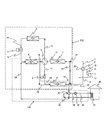
- FIG. 6 the air conditioner according to the second embodiment of the present invention will be described with reference to FIG. 6 and FIG. 7, but the same configuration as the air conditioner according to the first embodiment will be described.
- the same reference numerals are given and description thereof is omitted.
- subjected to the heat exchanger in FIG. 7 has shown the flow of heat.
- the air conditioner according to the second embodiment has a first bypass in the refrigerant pipe 11 that connects the compression cycle four-way valve 2 and the second heat source side heat exchanger 7.
- the three-way valve (bypass opening / closing means) 41 is incorporated into the refrigerant pipe 19 connecting the second utilization side heat exchanger 8 and the compression cycle four-way valve 2 to the second bypass three-way valve (bypass opening / closing means) 42. And connecting the first bypass three-way valve 41 and the second bypass three-way valve 42 with a bypass refrigerant pipe (bypass pipe) 43, that is, a flow path through which the refrigerant bypasses the compressor 1, that is, The bypass route is formed.
- the configuration in which the bypass route is provided in this way is different from that in the first embodiment.
- a natural circulation cycle TS2 using two heat source side heat exchangers 4 and 7 and two usage side heat exchangers 6 and 8 is formed.
- the operation mode No. described below can be performed.
- the operation by 5 becomes possible.
- the 1st heat source side heat exchanger 4 and the 2nd heat source side heat exchanger 7 have the almost same height position, or the 1st use side heat exchanger 6 is set.
- the first usage-side heat exchanger 6 and the second usage-side heat exchanger 8 are installed at substantially the same height as the second usage-side heat exchanger,
- the heat source side heat exchanger 4 and the second heat source side heat exchanger 7 are installed at a position higher than the first use side heat exchanger 6 and the second use side heat exchanger 8 so as to provide a head difference. I have to.
- the cycle switching four-way valve 3 is operated, the refrigerant pipe 12 and the refrigerant pipe 13 are connected, and the refrigerant pipe 16 and the refrigerant pipe 17 are connected. Further, the first bypass three-way valve 41 and the second bypass three-way valve 42 are operated to switch the refrigerant flow path so that the refrigerant flows through the bypass refrigerant pipe 43 without flowing into the compressor 1.
- Operation mode No. 5 is a cooling operation mode using only the natural circulation type cycle TS2, and the operation mode No. Similar to 4, it is used when the outside air temperature is considerably lower than the room temperature and the dehumidifying load is small (for example, when the room temperature rises due to solar radiation or internal load such as in the daytime in winter).
- the operation mode No. 5, the refrigerant circulation path is in the direction of the arrow in FIG.
- the refrigerant pipe 12 and the refrigerant pipe 13 communicate with each other and the refrigerant pipe 16 and the refrigerant pipe 17 communicate with each other by the cycle switching four-way valve 3. Further, the first bypass three-way valve 41 and the second bypass three-way valve 42 allow the refrigerant to flow through the bypass refrigerant pipe 43 without flowing into the compressor 1.
- Operation mode No. 5 the first expansion valve 5 is adjusted to a predetermined opening according to the amount of exchange heat desired to be obtained by the first use side heat exchanger 6, and the second expansion valve 9 is fully opened. .
- the operation mode No. In 5 the compressor 1 is stopped.
- the refrigerant staying in the first heat source side heat exchanger 4 and the second heat source side heat exchanger 7 dissipates heat to the atmosphere, condenses and liquefies.
- the liquid refrigerant having a high density flows toward the first usage-side heat exchanger 6 and the second usage-side heat exchanger 8 under the influence of gravity.
- the refrigerant that has flowed into the first usage-side heat exchanger 6 and the second usage-side heat exchanger 8 absorbs heat from the water circulating in the cold / hot water circulation circuit CW while flowing through the respective usage-side heat exchangers 6 and 8. Then, it evaporates and rises toward the second heat source side heat exchanger 7 due to the pressure gradient due to the density difference of the refrigerant. In this way, the refrigerant naturally circulates in the natural circulation type cycle TS2 due to the density difference.
- This operation mode No. 5 since the natural circulation type cycle TS2 can be formed by using the two heat source side heat exchangers 4 and 7 and the two usage side heat exchangers 6 and 8, the cooling capacity compared with the natural circulation type cycle TS1 described above. Will improve. Since the operation by the compressor 1 is not required, it is needless to say that the energy saving effect is high in that the power is not consumed. In addition, since the water in the cold / hot water circulation circuit CW is cooled by the 1st utilization side heat exchanger 6 and the 2nd utilization side heat exchanger 8, the air in the house 30 is cooled by the indoor heat exchanger 31. The Rukoto. That is, the operation mode No. Reference numeral 5 denotes a cooling operation mode.
- This operation mode No. 5 by operating the cycle switching four-way valve 3 to connect the refrigerant pipe 12 and the refrigerant pipe 17, and to connect the refrigerant pipe 13 and the refrigerant pipe 16, the natural circulation cycle TS 1 and the second Two natural circulation cycles of the natural circulation cycle using the heat source side heat exchanger 7 and the second utilization side heat exchanger 8 can also be formed.
- a general circulation system naturally circulation
- the cooling capacity can be ensured, or that switching to the operation mode No. 4 is facilitated according to fluctuations in the outside air temperature and the load.
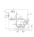
- FIGS. 8 to 14 An air conditioner according to a third embodiment of the present invention will be described with reference to FIGS. 8 to 14. The same configuration as that of the air conditioner according to the first embodiment will be described. The same reference numerals are given and the description thereof is omitted. 9 to 14, the arrows attached to the heat exchangers indicate the heat flow.
- the air conditioner according to the third embodiment uses air in the house 30 as a heat transfer medium on the use side, and uses the second use side heat exchanger 58 with the first divided heat exchanger 58a and the second heat exchanger 58.
- the divided heat exchanger 58b is divided into two, and a dehumidifying valve (third) is connected between the connecting refrigerant pipe 52a and the connecting refrigerant pipe 52b connecting the first divided heat exchanger 58a and the second divided heat exchanger 58b.
- the expansion valve) 51 is provided.
- This configuration is the main difference from the first embodiment. With this configuration, the air conditioner according to the third embodiment can be operated in the reheat dehumidifying operation mode in which the air in the house 30 is dehumidified while being warmed.
- the air in the house 30 is changed into the 1st utilization side heat exchanger 1 and the 2nd utilization side heat exchanger 58 (the 1st division
- the air conditioner according to the third embodiment is in a first state in which a natural circulation cycle TS3 and a first compression cycle PC3 described below can be used in combination. And, the refrigeration cycle can be switched by the cycle switching four-way valve 3 to the second state in which the second compression cycle PC4 can be used.
- the first heat source side heat exchanger 4 and the first expansion valve 5 are connected by a refrigerant pipe 14, and the first expansion valve 5 and the first use side heat exchanger 6 are connected to the refrigerant pipe.
- the first use side heat exchanger 6 and the cycle switching four-way valve 3 are connected by the refrigerant pipe 16
- the cycle switching four-way valve 3 and the first heat source side heat exchanger 4 are connected by the refrigerant pipe 13. It is a cycle that is connected and formed in an annular shape.
- the refrigerant circulates naturally in the natural circulation cycle TS3 due to the density difference.
- the discharge port 1b of the compressor 1 and the compression cycle four-way valve 2 are connected by a refrigerant pipe 10, and the compression cycle four-way valve 2 and the second heat source side heat exchanger 7 are connected.
- the refrigerant pipe 11 connects, the second heat source side heat exchanger 7 and the cycle switching four-way valve 3 are connected by the refrigerant pipe 12, and the cycle switching four-way valve 3 and the second expansion valve 9 are connected by the refrigerant pipe 17.
- the second expansion valve 9 and the first divided heat exchanger 58a are connected by the refrigerant pipe 18, the first divided heat exchanger 58a and the dehumidifying valve 51 are connected by the connecting refrigerant pipe 52a, and the dehumidifying valve 51 is connected.
- the second divided heat exchanger 58b are connected by a connecting refrigerant pipe 52b, the second divided heat exchanger 58b and the compression cycle four-way valve 2 are connected by a refrigerant pipe 19, and the compression cycle four-way valve 2 is connected.
- the suction port 1a of the compressor 1 are connected by a refrigerant pipe 20 and formed in an annular shape. It is a cycle. Then, the compressor 1 forcibly circulates the refrigerant in the first compression cycle PC3.
- the discharge port 1b of the compressor 1 and the compression cycle four-way valve 2 are connected by a refrigerant pipe 10, and the compression cycle four-way valve 2 and the second heat source side heat exchanger 7 are connected.
- the refrigerant pipe 11 is connected
- the second heat source side heat exchanger 7 and the cycle switching four-way valve 3 are connected by the refrigerant pipe 12
- the cycle switching four-way valve 3 and the first heat source side heat exchanger 4 are connected to the refrigerant pipe.
- the first heat source side heat exchanger 4 and the first expansion valve 5 are connected by a refrigerant pipe 14
- the first expansion valve 5 and the first use side heat exchanger 6 are connected by a refrigerant pipe 15.
- the first use side heat exchanger 6 and the cycle switching four-way valve 3 are connected by the refrigerant pipe 16
- the cycle switching four-way valve 3 and the second expansion valve 9 are connected by the refrigerant pipe 17, and the second
- the expansion valve 9 and the first divided heat exchanger 58a are connected by the refrigerant pipe 18, and the first divided heat exchanger 58a and the dehumidifying valve are connected.
- 1 is connected by a connecting refrigerant pipe 52a
- the dehumidification valve 51 and the second divided heat exchanger 58b are connected by a connecting refrigerant pipe 52b
- the second divided heat exchanger 58b and the compression cycle four-way valve 2 are connected.
- This is a cycle formed by connecting the refrigerant pipe 19 and connecting the compression cycle four-way valve 2 and the suction port 1a of the compressor 1 with the refrigerant pipe 20 in an annular shape. Then, the compressor 1 forcibly circulates the refrigerant in the second compression cycle PC4.
- Operation mode No. 6 is a reheat dehumidifying operation mode using the second compression cycle PC4 alone.
- the room temperature is higher than the set temperature, the room humidity is slightly higher than the set humidity, and heating and cooling dehumidification are required. This mode is used for load conditions.
- the refrigerant pipe 10 and the refrigerant pipe 11 are communicated with each other, and the refrigerant pipe 19 and the refrigerant pipe 20 are communicated with each other by the compression cycle four-way valve 2.
- the cycle switching four-way valve 3 allows the refrigerant pipe 12 and the refrigerant pipe 13 to communicate with each other, and the refrigerant pipe 16 and the refrigerant pipe 17 to communicate with each other.
- the second compression cycle PC4 is formed by switching the compression cycle four-way valve 2 and the cycle switching four-way valve 3 in this manner.
- the operation mode No. 6 the first expansion valve 5 and the second expansion valve 9 are fully opened, and the dehumidification valve 51 is adjusted to a predetermined opening degree.
- the high-temperature and high-pressure gas refrigerant discharged from the discharge port 1b of the compressor 1 flows through the second heat source side heat exchanger 7 and the first heat source side heat exchanger 4 in this order, it is a heat transfer medium on the heat source side. It dissipates heat to a certain atmosphere, condenses, and flows into the first usage-side heat exchanger 6 in a gas-liquid two-phase state.
- the refrigerant in the gas-liquid two-phase state is condensed by dissipating heat to the air in the house 30 that is the use-side heat transfer medium while flowing through the first use-side heat exchanger 6, and then the first While flowing through the divided heat exchanger 58a, the heat is similarly released to the air in the house 30 and further condensed and liquefied.
- the liquefied refrigerant is depressurized and expanded by the dehumidifying valve 51 to be in a gas-liquid two-phase state.
- the refrigerant in the gas-liquid two-phase state is evaporated and gasified by absorbing heat from the air in the house 30 while flowing through the second divided heat exchanger 52b.
- the gasified refrigerant flows into the suction port 1a of the compressor 1 and is compressed again by the compressor 1 to become a high-temperature and high-pressure gas refrigerant.
- Operation mode No. 7 is a reheat dehumidifying operation mode that uses the second compression cycle PC4 alone.
- the indoor temperature is higher than the set temperature
- the indoor humidity is higher than the set humidity
- the load condition requires cooling dehumidification and heating. The mode used.
- the open / closed state of the second expansion valve 9 and the dehumidifying valve 51 is the operation mode No. 6 and operation mode no. 7 and the operation mode no. 7, the first expansion valve 5 is fully open, the second expansion valve 9 is adjusted to a predetermined opening degree, and the dehumidifying valve 51 is fully open.
- the liquefied refrigerant is decompressed and expanded by the second expansion valve 9 to be in a gas-liquid two-phase state.
- the refrigerant in a gas-liquid two-phase state evaporates by absorbing heat from the air in the house 30 while flowing through the first divided heat exchanger 58a, and then passes through the second divided heat exchanger 58b. Similarly, during the flow, heat is absorbed from the air in the house 30 to further evaporate and gasify.
- the gasified refrigerant flows into the suction port 1a of the compressor 1 and is compressed again by the compressor 1 to become a high-temperature and high-pressure gas refrigerant.
- Operation mode No. 8 is a reheat dehumidifying operation mode using the second compression cycle PC4 alone.
- the indoor temperature is lower than the set temperature
- the indoor humidity is higher than the set humidity
- the load conditions require heating and cooling dehumidification.
- the refrigerant circulation path in FIG. 8 is the direction of the arrow in FIG. The route is opposite to 6.
- the refrigerant pipe 10 and the refrigerant pipe 19 communicate with each other and the refrigerant pipe 11 and the refrigerant pipe 20 communicate with each other by the compression cycle four-way valve 2.
- the cycle switching four-way valve 3 allows the refrigerant pipe 12 and the refrigerant pipe 13 to communicate with each other, and the refrigerant pipe 16 and the refrigerant pipe 17 to communicate with each other.
- the operation mode No. 8 the first expansion valve 5 and the second expansion valve 9 are fully opened, and the dehumidification valve 51 is adjusted to a predetermined opening degree.
- the high-temperature and high-pressure gas refrigerant discharged from the discharge port 1b of the compressor 1 dissipates heat and condenses to the air in the house 30 which is the heat transfer medium on the use side while flowing through the second divided heat exchanger 58b. Liquefy.
- the liquefied refrigerant is depressurized and expanded by the dehumidifying valve 51, evaporates and becomes a gas-liquid two-phase state. While the refrigerant in the gas-liquid two-phase state flows through the first divided heat exchanger 58a, the refrigerant absorbs heat from the air in the house 30 and evaporates, and then flows through the first usage-side heat exchanger 6. Similarly, it absorbs heat from the air in the house 30 and further evaporates.
- the refrigerant in the gas-liquid two-phase state that has exited the first use-side heat exchanger 6 flows through the first heat source-side heat exchanger 4 and the second heat source-side heat exchanger 7 while carrying the heat on the heat source side. It absorbs heat from the atmosphere of the medium and evaporates to gasify.
- the gasified refrigerant flows into the suction port 1a of the compressor 1 and is compressed again by the compressor 1 to become a high-temperature and high-pressure gas refrigerant.
- Operation mode No. 9 is a reheat dehumidifying operation mode that uses the second compression cycle PC4 alone.
- the room temperature is lower than the set temperature, the room humidity is slightly higher than the set humidity, and heating and some dehumidification are required. This mode is used for load conditions.
- This operation mode No. 9 is a reheat dehumidifying operation mode that uses the second compression cycle PC4 alone.
- the room temperature is lower than the set temperature, the room humidity is slightly higher than the set humidity, and heating and some dehumidification are required. This mode is used for load conditions.
- the refrigerant pipe 10 and the refrigerant pipe 19 communicate with each other and the refrigerant pipe 11 and the refrigerant pipe 20 communicate with each other by the compression cycle four-way valve 2.
- the cycle switching four-way valve 3 allows the refrigerant pipe 12 and the refrigerant pipe 13 to communicate with each other, and the refrigerant pipe 16 and the refrigerant pipe 17 to communicate with each other.
- the operation mode No. 9 the first expansion valve 5 is fully open, the second expansion valve 9 is adjusted to a predetermined opening degree, and the dehumidification valve 51 is fully open.
- the high-temperature and high-pressure gas refrigerant discharged from the discharge port 1b of the compressor 1 dissipates heat and condenses to the air in the house 30 which is the heat transfer medium on the use side while flowing through the second divided heat exchanger 58b. Subsequently, while flowing through the first divided heat exchanger 58a, the heat is similarly released to the air in the house 30 to be condensed and liquefied.
- the liquefied refrigerant is depressurized and expanded by the second expansion valve 9 and evaporated to be in a gas-liquid two-phase state.
- the refrigerant in the gas-liquid two-phase state absorbs heat from the air in the house 30 and further evaporates while flowing through the first usage-side heat exchanger 6.
- the refrigerant in the gas-liquid two-phase state that has exited the first use-side heat exchanger 6 flows through the first heat source-side heat exchanger 4 and the second heat source-side heat exchanger 7 while carrying the heat on the heat source side. It absorbs heat from the atmosphere of the medium and evaporates to gasify.
- the gasified refrigerant flows into the suction port 1a of the compressor 1 and is compressed again by the compressor 1 to become a high-temperature and high-pressure gas refrigerant.
- Operation mode No. 10 is a reheat dehumidifying operation mode using both the natural circulation type cycle TS3 and the first compression type cycle PC3. Since the room temperature is slightly higher than the set temperature and the room humidity is higher than the set humidity, cooling dehumidification and heating are performed. Is a mode used when the outside air temperature is considerably lower than the room temperature.
- This operation mode No. 10 the refrigerant circulation path is in the direction of the arrow in FIG.
- the refrigerant pipe 10 and the refrigerant pipe 11 are communicated with each other, and the refrigerant pipe 19 and the refrigerant pipe 20 are communicated with each other by the compression cycle four-way valve 2.
- the cycle switching four-way valve 3 allows the refrigerant pipe 12 and the refrigerant pipe 17 to communicate with each other, and the refrigerant pipe 13 and the refrigerant pipe 16 to communicate with each other.
- the operation mode No. 10 the first expansion valve 5 is adjusted to a predetermined opening according to the amount of exchange heat desired to be obtained by the first use side heat exchanger 6, and the second expansion valve 9 is fully open.
- the dehumidifying valve 51 is adjusted to a predetermined opening degree.
- the high-temperature and high-pressure gas refrigerant discharged from the discharge port 1b of the compressor 1 is a heat transfer medium on the heat source side while flowing through the second heat source side heat exchanger 7. It dissipates heat to a certain atmosphere, condenses, and flows into the first divided heat exchanger 58a in a gas-liquid two-phase state.
- the refrigerant in the gas-liquid two-phase state is condensed and liquefied by dissipating heat to the air in the house 30 that is the heat transfer medium on the use side while flowing through the first split-side heat exchanger 58a.
- the liquefied refrigerant is depressurized and expanded by the dehumidifying valve 51 to be in a gas-liquid two-phase state.
- the refrigerant in the gas-liquid two-phase state is evaporated and gasified by absorbing heat from the air in the house 30 while flowing through the second divided heat exchanger 52b.
- the gasified refrigerant flows into the suction port 1a of the compressor 1 and is compressed again by the compressor 1 to become a high-temperature and high-pressure gas refrigerant.
- the refrigerant staying in the first heat source side heat exchanger 4 dissipates heat to the atmosphere and condenses and liquefies.
- the liquid refrigerant having a high density descends under the influence of gravity, passes through the first expansion valve 5, absorbs heat from the air in the house 30 while flowing through the first use side heat exchanger 6, and evaporates. To do.
- the evaporated refrigerant flows toward the first heat source side heat exchanger 4.
- This operation mode No. 10 the air in the house 30 is cooled by the first use side heat exchanger 6, reheated by the first divided heat exchanger 58a, and cooled and dehumidified by the second divided heat exchanger 58b. . Therefore, even when the outside air temperature is equal to or lower than the room temperature of the house 30 and the difference between the outside air temperature and the room temperature is small, by using the natural circulation cycle TS3 and the first compression cycle PC3 in combination. Thus, appropriate cooling and dehumidification and heating can be performed, and a desired temperature and humidity environment can be obtained. Therefore, the dehumidifying capacity can be increased as compared with the natural circulation cycle.
- Operation mode No. 11 is a reheat dehumidifying operation mode using both the natural circulation cycle TS3 and the first compression cycle PC3. Although the room temperature is lower than the set temperature, the room humidity is higher than the set humidity. This is a mode that is used when the load conditions are necessary and the outside air temperature is considerably lower than the room temperature. This operation mode No.
- the refrigerant pipe 10 and the refrigerant pipe 19 communicate with each other and the refrigerant pipe 11 and the refrigerant pipe 20 communicate with each other by the compression cycle four-way valve 2.
- the cycle switching four-way valve 3 allows the refrigerant pipe 12 and the refrigerant pipe 17 to communicate with each other, and the refrigerant pipe 13 and the refrigerant pipe 16 to communicate with each other.
- the operation mode No. 11 the first expansion valve 5 is adjusted to a predetermined opening according to the amount of exchange heat desired to be obtained by the first use side heat exchanger 6, and the second expansion valve 9 is fully open.
- the dehumidifying valve 51 is adjusted to a predetermined opening degree.
- the high-temperature and high-pressure gas refrigerant discharged from the discharge port 1b of the compressor 1 is a heat transfer medium on the use side while flowing through the second divided heat exchanger 58b. It dissipates heat to the air in the house 30 and condenses and liquefies.
- the liquefied refrigerant is depressurized and expanded by the dehumidifying valve 51 to be in a gas-liquid two-phase state. While the refrigerant in the gas-liquid two-phase state flows through the first split heat exchanger 58a, the refrigerant absorbs heat from the air in the house 30 and evaporates.
- the second heat source side heat exchanger 7 While flowing through the second heat source side heat exchanger 7, It evaporates and gasifies by absorbing heat from the atmosphere, which is a heat transfer medium on the heat source side.
- the gasified refrigerant flows into the suction port 1a of the compressor 1 and is compressed again by the compressor 1 to become a high-temperature and high-pressure gas refrigerant.
- the refrigerant staying in the first heat source side heat exchanger 4 dissipates heat to the atmosphere and condenses and liquefies.
- the liquid refrigerant having a high density descends under the influence of gravity, passes through the first expansion valve 5, absorbs heat from the air in the house 30 while flowing through the first use side heat exchanger 6, and evaporates. To do.
- the evaporated refrigerant flows toward the first heat source side heat exchanger 4.
- This operation mode No. 11 the air in the house 30 is cooled by the first use side heat exchanger 6, cooled and dehumidified by the first divided heat exchanger 58a, and reheated by the second divided heat exchanger 58b. . Therefore, by using the natural circulation cycle TS3 and the first compression cycle PC3 in combination even when the outside air temperature is equal to or lower than the indoor temperature of the house 30, especially when the difference between the outside air temperature and the indoor temperature is small. Thus, appropriate cooling and dehumidification and heating can be performed, and a desired temperature and humidity environment can be obtained. Therefore, the dehumidifying capacity can be increased as compared with the natural circulation cycle.
- the operation mode No. 10 no. It goes without saying that when the compressor 1 is stopped at 11, the operation using only the natural circulation cycle TS3 can be performed.
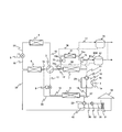
- the air conditioner according to the fourth embodiment forms an intermediate hot water circulation circuit (heat source side heat transfer medium circulation circuit) MW including the second heat source side heat exchanger 7, and the inside of the intermediate hot water circulation circuit MW 3 is characterized in that water is circulated as a heat transfer medium on the heat source side.
- intermediate hot water circulation circuit heat source side heat transfer medium circulation circuit
- the intermediate hot water circulation circuit MW is an annular circuit formed by connecting the second heat source side heat exchanger 7 and the heat storage tank 61 with intermediate hot water pipes (heat source side heat transfer medium pipes) 62 and 63.
- the water is forcibly circulated in the intermediate hot water circulation circuit MW by a circulation pump (not shown).
- the heat storage tank 61 is filled with a heat storage material.
- the operation mode No. described above is used. 1 and no. 3, the temperature of the refrigerant is released to the outside by the second heat source side heat exchanger 7, and the water flowing in the intermediate hot water circulation circuit MW is heated from the second heat source side heat exchanger 7. Absorb. The hot heat absorbed by the water is stored in the heat storage tank 61, and the water circulating in the intermediate hot water circulation circuit MW becomes intermediate hot water.
- the intermediate hot water can be made by effectively utilizing the exhaust heat of the second heat source side heat exchanger 7.
- the second heat source side heat exchanger 7 can be used as an evaporator of a hot water supply cycle. Specifically, as shown in FIG. 15, a hot water supply compressor 71, a hot water supply condenser 72, a hot water supply expansion valve 73, and a second heat source side heat exchanger 7 are sequentially connected by hot water supply refrigerant pipes 74a to 74d. Thus, an annular hot water supply cycle is formed, and a hot water supply system for supplying hot water is constructed by connecting the hot water supply condenser 72 and the hot water storage tank 75 with hot water supply pipes 76 and 77.
- the gas-liquid two-phase hot water supply refrigerant decompressed and expanded by the hot water supply expansion valve 73 absorbs heat from the second heat source side heat exchanger 7 and evaporates to be gasified. That is, in the hot water supply cycle, the second heat source side heat exchanger 7 functions as an evaporator.
- the heat transfer medium on the heat source side that exchanges heat with the second heat source side heat exchanger 7 serves as a hot water supply refrigerant.
- the 2nd heat source side heat exchanger 7 can be utilized for both a hot-water supply system and an air-conditioning system, cost can be reduced.
- R134a, HFO1234yf, HFO1234ze, CO2, or the like may be used as the hot water supply refrigerant.
- the heat exchanger used for the natural cycle can be used as the heat exchanger for the compression cycle, so that the efficiency of heat exchange can be increased.
- the natural circulation type cycle and the compression type cycle can be used together, the dehumidifying ability is increased even when the outside air temperature is equal to or lower than the room temperature and the difference between the outside air temperature and the room temperature is small. Can do.
- the exhaust heat of the heat exchanger can be used for water supply or hot water supply equipment, so that energy can be used effectively.
- SYMBOLS 1 Compressor, 1a ... Suction port, 1b ... Discharge port, 2 ... Four-way valve for compression cycle (flow path switching valve), 3 ... Four-way valve for cycle switching (cycle switching means), 4 ... First heat source side Heat exchanger, 5 ... 1st expansion valve, 6 ... 1st user side heat exchanger, 7 ... 2nd heat source side heat exchanger, 8 ... 2nd user side heat exchanger, 9 ... 2nd Expansion valve, 10-20 ... refrigerant pipe, 30 ... house (cooled space), 31 ... indoor heat exchanger, 32 ... circulating pump, 33 ... four-way valve for cold / hot water circuit, 35-40 ...
Abstract
In order to exert cooling and heating abilities using a natural circulation cycle heat exchanger as the heat exchanger of a pressure cycle, the disclosed air conditioner has a configuration that can form at least three refrigeration cycles: a natural circulation cycle (TS1) formed in a loop by sequentially connecting with pipework a first heat-source-side heat exchanger (4), a first expansion valve (5), and a first use-side heat exchanger (6); a first pressure cycle (PC1) formed in a loop by sequentially connecting with pipework the discharge port (1b) of a compressor (1), a duct switching valve (2), a second heat-source-side heat exchanger (7), a second expansion valve (9), a second use-side heat exchanger (8), and the intake port (1a) of the compressor; and a second pressure cycle (PC2) formed in a loop by sequentially connecting with pipework the discharge port (1b) of the compressor, the duct switching valve (2), the second heat-source-side heat exchanger (7), the first heat-source-side heat exchanger (4), the first expansion valve (5), the first use-side heat exchanger (6), the second use-side heat exchanger (8), and the intake port (1a) of the compressor.
Description
本発明は、例えば住宅や事務所ビルなどに設置される空気調和装置に係り、特に、冷媒が密度差により自然循環する自然循環式サイクルと、圧縮機により冷媒が強制循環する圧縮式サイクルとを併設し、それら2つの冷凍サイクルを使い分けることが可能な空気調和装置に関する。
The present invention relates to an air conditioner installed in, for example, a house or an office building, and in particular, includes a natural circulation cycle in which refrigerant naturally circulates due to a density difference and a compression cycle in which refrigerant is forced to circulate by a compressor. The present invention relates to an air conditioner that can be used side by side and can selectively use these two refrigeration cycles.
自然循環式サイクルと圧縮式サイクルとの2つの冷凍サイクルを使い分ける従来技術として、例えば、特許文献1には、箱体内の空気を冷却するために、圧縮機、再熱用凝縮器、および冷却器を冷媒配管で順次接続して形成された冷凍サイクル(圧縮式サイクル)と、自然循環冷却用凝縮器と自然循環冷却用冷却器とを冷媒配管で接続して形成された自然循環冷却装置(自然循環式サイクル)とを併設した技術が開示されている。この特許文献1によると、自然循環冷却装置(自然循環式サイクル)によって箱体内の空気を冷却することができるため、冷凍サイクル(圧縮式サイクル)による冷却の負担は軽減される。よって、特許文献1に記載の技術によれば、消費電力を削減することができ、冷却システム全体の運転コストを低く抑えることができる。
As a conventional technique for selectively using two refrigeration cycles, a natural circulation cycle and a compression cycle, for example, Patent Document 1 discloses a compressor, a reheat condenser, and a cooler for cooling the air in the box. Refrigeration cycle (compression cycle) formed by connecting refrigerant pipes sequentially, natural circulation cooling condenser (natural circulation cooling system) formed by connecting condensers for natural circulation cooling and natural circulation cooling coolers (natural And a cycle-type cycle) is disclosed. According to this patent document 1, since the air in the box can be cooled by the natural circulation cooling device (natural circulation type cycle), the burden of cooling by the refrigeration cycle (compression type cycle) is reduced. Therefore, according to the technique described in Patent Document 1, it is possible to reduce power consumption and to reduce the operating cost of the entire cooling system.
また、特許文献2には、室内熱交換器と、室外熱交換器と、冷媒配管と、膨張弁と、別装置の圧縮冷凍機に相当する冷媒圧縮強制循環装置とを備えた冷媒自然循環冷却除湿装置が開示されている。この冷媒自然循環冷却除湿装置は、室外熱交換器と、この室外熱交換器より低い位置にある室内熱交換器と、膨張弁とを冷媒配管で環状に接続して形成された自然循環式サイクルと、冷媒圧縮強制循環装置による圧縮式サイクルとを有しており、自然循環式サイクルの室外熱交換器に対して圧縮式サイクルの蒸発熱交換器が密結合した構成となっている。この構成によれば、蒸発熱交換器は、室外熱交換器から熱を効率的に奪うことができるため、室内と室外との気温差が無くなり冷却除湿能力が低下したような場合であっても、冷媒圧縮強制循環装置を稼働することにより、冷媒自然循環冷却除湿装置の冷却除湿能力の低下を補うことができる。
Patent Document 2 discloses a natural refrigerant cooling system including an indoor heat exchanger, an outdoor heat exchanger, a refrigerant pipe, an expansion valve, and a refrigerant compression forced circulation device corresponding to a compression refrigerator of another device. A dehumidifying device is disclosed. This natural circulation cooling dehumidification device is a natural circulation cycle formed by connecting an outdoor heat exchanger, an indoor heat exchanger at a position lower than the outdoor heat exchanger, and an expansion valve in an annular shape with refrigerant piping. And a compression cycle using a refrigerant compression forced circulation device, and an evaporative heat exchanger of the compression cycle is tightly coupled to an outdoor heat exchanger of the natural circulation cycle. According to this configuration, since the evaporative heat exchanger can efficiently take heat from the outdoor heat exchanger, even when the temperature difference between the indoor and the outdoor is eliminated and the cooling and dehumidifying capacity is reduced. By operating the refrigerant compression forced circulation device, it is possible to compensate for a decrease in the cooling and dehumidifying capability of the refrigerant natural circulation cooling and dehumidifying device.
さらに、特許文献2には、冷媒圧縮強制循環系を用いた冷媒圧縮強制循環冷暖房両用装置(圧縮式サイクル)に、冷媒自然循環を用いた冷媒自然循環冷却除湿装置(自然循環式サイクル)を併設した空気調和装置が開示されている。この空気調和装置によれば、冷媒自然循環冷却除湿装置により除湿を行いながら、冷媒圧縮強制循環冷暖房両用装置により暖房するような質の高いドライ運転モードを行うことができ、快適性を高めることができる。
Furthermore, in Patent Document 2, a refrigerant natural circulation cooling and dehumidifying device (natural circulation type cycle) using refrigerant natural circulation is added to a refrigerant compression forced circulation cooling / heating device (compression type cycle) using a refrigerant compression forced circulation system. An air conditioning apparatus is disclosed. According to this air conditioner, it is possible to perform a high-quality dry operation mode in which heating is performed by the refrigerant compression forced circulation cooling / heating dual-purpose device while dehumidification is performed by the refrigerant natural circulation cooling / dehumidifying device, thereby improving comfort. it can.
しかしながら、上記従来の技術では、何れも自然循環式サイクルと圧縮式サイクルとが独立した冷凍サイクルを構成しているので、自然循環式サイクルの熱交換器を、冷暖房のピーク時などに圧縮式サイクルの熱交換器として利用することは不可能であった。そのため、自然循環式サイクルの熱交換器の熱交換機能が有効に活用されていないといった課題があった。
However, in each of the above conventional technologies, the natural circulation cycle and the compression cycle constitute an independent refrigeration cycle. Therefore, the heat exchanger of the natural circulation cycle is connected to the compression cycle at the peak of air conditioning. It was impossible to use as a heat exchanger. Therefore, the subject that the heat exchange function of the heat exchanger of a natural circulation type cycle was not utilized effectively occurred.
また、自然循環式サイクルは、2つの熱交換器間にヘッド差を設けておき、密度差により冷媒が自然に循環するサイクルであるため、外気温度が室内温度以下の場合であって、外気温度と室内温度の差が小さいときには、自然循環式サイクルを利用した冷房運転を行っても、除湿能力が得られないといった課題があった。
The natural circulation type cycle is a cycle in which a head difference is provided between two heat exchangers, and the refrigerant naturally circulates due to a density difference. When the difference between the room temperature and the room temperature is small, there is a problem that the dehumidifying ability cannot be obtained even if the cooling operation using the natural circulation type cycle is performed.
本発明は、上記した実情に鑑みてなされたものであり、その目的は、圧縮式サイクルと自然循環式サイクルとを併設した空気調和装置において、自然循環式サイクルの熱交換器を圧縮式サイクルの熱交換器として利用して冷暖房能力を発揮させることにある。また、本発明は、外気温度が室内温度以下の場合に、自然循環式サイクルと圧縮式サイクルを併用することにより、外気温度と室内温度の差が小さいときでも除湿能力を高めることができる空気調和装置を提供することも目的としている。
The present invention has been made in view of the above-described circumstances, and an object of the present invention is to provide a natural circulation cycle heat exchanger for a compression cycle in an air conditioner provided with a compression cycle and a natural circulation cycle. It is to be used as a heat exchanger to exhibit air conditioning capability. The present invention also provides an air conditioning system that can enhance the dehumidification capability even when the difference between the outside air temperature and the room temperature is small by using both the natural circulation cycle and the compression cycle when the outside air temperature is equal to or lower than the room temperature. It is also an object to provide an apparatus.
上記目的を達成するために、本発明の空気調和装置は、圧縮機と、熱源側の熱搬送媒体と冷媒とを熱交換させる第1および第2の熱源側熱交換器と、利用側の熱搬送媒体と冷媒とを熱交換させる第1および第2の利用側熱交換器と、冷媒の流路方向を切り替える流路切替弁と、第1および第2の膨張弁とを備えた空気調和装置であって、前記第1の熱源側熱交換器、前記第1の膨張弁および前記第1の熱源側熱交換器よりも低い位置に設置された前記第1の利用側熱交換器を順次冷媒配管で接続して環状に形成され、冷媒が密度差により自然循環する自然循環式サイクルと、前記圧縮機の吐出口、前記流路切替弁、前記第2の熱源側熱交換器、前記第2の膨張弁、前記第2の利用側熱交換器、および前記圧縮機の吸込口を順次冷媒配管で接続して環状に形成され、前記圧縮機により冷媒が強制循環する第1の圧縮式サイクルと、前記圧縮機の吐出口、前記流路切替弁、前記第2の熱源側熱交換器、前記第1の熱源側熱交換器、前記第1の膨張弁、前記第1の利用側熱交換器、前記第2の利用側熱交換器、および前記圧縮機の吸込口を順次冷媒配管で接続して環状に形成され、前記圧縮機により冷媒が強制循環する第2の圧縮式サイクルとの少なくとも3つの冷凍サイクルを形成可能であり、前記自然循環式サイクルと前記第1の圧縮式サイクルとが独立して形成される第1の状態と、前記第2の圧縮式サイクルが形成される第2の状態とに冷凍サイクルを切り替えるサイクル切替手段を備えている。
In order to achieve the above object, an air conditioner of the present invention includes a compressor, first and second heat source side heat exchangers that exchange heat between the heat transfer medium on the heat source side and the refrigerant, and heat on the use side. An air conditioner including first and second usage-side heat exchangers that exchange heat between the transport medium and the refrigerant, a flow path switching valve that switches a flow path direction of the refrigerant, and first and second expansion valves The first heat source side heat exchanger, the first expansion valve, and the first heat source side heat exchanger installed at a position lower than the first heat source side heat exchanger are sequentially refrigerant. A natural circulation cycle that is formed in an annular shape by connecting with piping, and the refrigerant circulates naturally due to a density difference, a discharge port of the compressor, the flow path switching valve, the second heat source side heat exchanger, the second The expansion valve, the second user-side heat exchanger, and the suction port of the compressor are sequentially connected by refrigerant piping. A first compression cycle in which the refrigerant is forcedly circulated by the compressor, a discharge port of the compressor, the flow path switching valve, the second heat source side heat exchanger, the first The heat source side heat exchanger, the first expansion valve, the first usage side heat exchanger, the second usage side heat exchanger, and the compressor suction port are sequentially connected by a refrigerant pipe to form an annular shape. At least three refrigeration cycles, and a second compression cycle in which the refrigerant is forcedly circulated by the compressor, and the natural circulation cycle and the first compression cycle are independent of each other. Cycle switching means for switching the refrigeration cycle between the first state to be formed and the second state in which the second compression cycle is formed is provided.
本発明によれば、サイクル切替手段を操作して第2の圧縮式サイクルに切り替えると、自然循環式サイクルの熱交換器を第2の圧縮式サイクルの熱交換器として利用できるため、冷暖房能力を高めることができ、特に、冷暖房ピーク時に大きな効果を発揮することとなる。
According to the present invention, when the cycle switching means is operated to switch to the second compression cycle, the heat exchanger of the natural circulation cycle can be used as the heat exchanger of the second compression cycle. In particular, a large effect is exhibited at the peak of air conditioning.
また、本発明は、上記構成において、前記第1の利用側熱交換器、前記第2の利用側熱交換器、および被冷却空間に設置された室内熱交換器を利用側熱搬送媒体用配管で順次接続して環状の利用側熱搬送媒体循環回路を形成し、前記利用側熱搬送媒体循環回路に、前記利用側の熱搬送媒体としての水またはブラインを強制循環させるようにしたことを特徴としている。
Moreover, this invention is a pipe | tube for utilization side heat transfer media in the said structure in the said 1st utilization side heat exchanger, the said 2nd utilization side heat exchanger, and the indoor heat exchanger installed in the to-be-cooled space. Are connected in order to form an annular use-side heat transfer medium circulation circuit, and water or brine as the use-side heat transfer medium is forcibly circulated in the use-side heat transfer medium circulation circuit. It is said.
本発明によれば、利用側熱搬送媒体循環回路を設け、被冷却空間に設置された室内熱交換器を介して被冷却空間の空気を冷暖房等する構成となっているため、従来のように室内機と室外機をつなぐ冷媒配管が不要となるうえ、冷媒量が少なくて済む。また、従来のような室内機と室外機とを冷媒配管で接続する構成において自然循環式サイクルを形成する場合には、室外機を室内機よりも高い位置に設置する必要があり、レイアウトの制約があった。ところが、本発明によれば、利用側熱搬送媒体循環回路を設ける構成であるため、レイアウトの自由度が増すという利点がある。
According to the present invention, the use side heat transfer medium circulation circuit is provided, and the air in the space to be cooled is cooled and heated via the indoor heat exchanger installed in the space to be cooled. Refrigerant piping connecting the indoor unit and the outdoor unit is not necessary, and the amount of refrigerant is small. In addition, when a natural circulation cycle is formed in a conventional configuration in which an indoor unit and an outdoor unit are connected by a refrigerant pipe, the outdoor unit must be installed at a higher position than the indoor unit, and layout restrictions are imposed. was there. However, according to the present invention, since the use side heat transfer medium circulation circuit is provided, there is an advantage that the degree of freedom in layout increases.
また、本発明は、上記構成において、前記第2の利用側熱交換器を、第1の分割熱交換器と第2の分割熱交換器とに2分割し、前記第1の分割熱交換器と前記第2の分割熱交換器とを繋ぐ連結用冷媒配管に第3の膨張弁を設けたことを特徴としている。
Moreover, this invention divides the said 2nd utilization side heat exchanger into the 1st division | segmentation heat exchanger and the 2nd division | segmentation heat exchanger in the said structure, The said 1st division | segmentation heat exchanger And a third expansion valve in the connecting refrigerant pipe connecting the second divided heat exchanger.
本発明によれば、第1の分割熱交換器と第2の分割熱交換器と第3の膨張弁とにより、被冷却空間の空気を暖めながら除湿する再熱除湿運転を行うことができる。しかも、自然循環式サイクルと第1の圧縮式サイクルを併用することができるので、外気温度が室内温度以下の場合であって、外気温度と室内温度の差が小さいときでも除湿能力を高めることができる。加えて、温度、湿度の制御範囲が広くなるといった利点もある。
According to the present invention, the reheat dehumidifying operation for dehumidifying the air in the space to be cooled can be performed by the first divided heat exchanger, the second divided heat exchanger, and the third expansion valve. In addition, since the natural circulation cycle and the first compression cycle can be used in combination, the dehumidifying capacity can be increased even when the outside air temperature is equal to or lower than the room temperature and the difference between the outside temperature and the room temperature is small. it can. In addition, there is an advantage that the control range of temperature and humidity is widened.
また、本発明は、上記構成において、前記第2の熱源側熱交換器および蓄熱タンクを熱源側熱搬送媒体用配管で接続して環状の熱源側熱搬送媒体循環回路を形成し、前記熱源側熱搬送媒体循環回路に、前記熱源側の熱搬送媒体としての水を強制循環させるようにしたことを特徴としている。
Further, the present invention is the above configuration, wherein the second heat source side heat exchanger and the heat storage tank are connected by a heat source side heat transfer medium pipe to form an annular heat source side heat transfer medium circulation circuit, and the heat source side The heat transfer medium circulation circuit is characterized in that water as the heat transfer medium on the heat source side is forcibly circulated.
本発明によれば、熱源側熱交換器の排熱を利用して中間温水を作ることもできるため、この中間温水を給湯などに用いることにより、効率が向上する。さらに、本発明では、蓄熱タンクにより熱源側熱交換器の排熱を蓄熱できるため、例えば、空調負荷と給湯負荷の時間帯の相違を解消することも可能である。
According to the present invention, since the intermediate hot water can be made using the exhaust heat of the heat source side heat exchanger, the efficiency is improved by using this intermediate hot water for hot water supply or the like. Furthermore, in the present invention, since the exhaust heat of the heat source side heat exchanger can be stored by the heat storage tank, for example, it is possible to eliminate the difference between the time zones of the air conditioning load and the hot water supply load.
また、本発明によれば、上記構成において、給湯用圧縮機、給湯用利用側熱交換器、給湯用膨張弁、および前記第2の熱源側熱交換器を順次給湯用冷媒配管で接続して環状の給湯サイクルを形成し、前記給湯サイクルに、前記熱源側の熱搬送媒体としての給湯用冷媒を前記給湯用圧縮機により強制循環させるようにしたことを特徴としている。
According to the present invention, in the above configuration, the hot water supply compressor, the hot water use side heat exchanger, the hot water supply expansion valve, and the second heat source side heat exchanger are sequentially connected by the hot water supply refrigerant pipe. An annular hot water supply cycle is formed, and hot water supply refrigerant as a heat transfer medium on the heat source side is forcibly circulated by the hot water supply compressor in the hot water supply cycle.
本発明によれば、中間温水よりも高温の温水を生成することができる。
According to the present invention, hot water having a temperature higher than that of the intermediate hot water can be generated.
また、本発明は、上記構成において、前記圧縮機の吸込口と吐出口とをバイパスするバイパス配管と、冷媒の流路を、前記圧縮機を経由する流路と前記バイパス配管を経由する流路との何れの流路にするかを切り替えるバイパス開閉手段とを設けたことを特徴としている。
Further, in the above configuration, the present invention provides a bypass pipe that bypasses the suction port and the discharge port of the compressor, a refrigerant flow path, a flow path that passes through the compressor, and a flow path that passes through the bypass pipe. And a bypass opening / closing means for switching between the flow paths.
本発明によれば、2つの熱源側熱交換器と2つの利用側熱交換器を用いた自然循環式サイクルを形成できるので、熱交換の効率の高い自然循環サイクルによる運転が可能となり、省エネを図ることができる。
According to the present invention, since a natural circulation cycle using two heat source side heat exchangers and two utilization side heat exchangers can be formed, it is possible to operate with a natural circulation cycle with high heat exchange efficiency, and to save energy. Can be planned.
本発明によれば、自然循環式サイクルの熱交換器を圧縮式サイクルの熱交換器として利用できるため、圧縮式サイクルの熱交換器のみを利用するのに比べて、熱交換器の伝熱面積が広くなり、熱交換効率が向上し、省エネを図ることができる。また、自然循環式サイクルと圧縮式サイクルとを併用できるため、外気温度が室内温度以下の場合であって、外気温度と室内温度の温度差が小さいときでも、除湿能力を高めることができる。
According to the present invention, the heat exchanger of the natural circulation type cycle can be used as the heat exchanger of the compression type cycle, so that the heat transfer area of the heat exchanger is larger than that using only the heat exchanger of the compression type cycle. Becomes wider, heat exchange efficiency is improved, and energy can be saved. In addition, since the natural circulation cycle and the compression cycle can be used in combination, the dehumidifying ability can be increased even when the outside air temperature is equal to or lower than the room temperature and the temperature difference between the outside temperature and the room temperature is small.
[本発明の第1の実施形態]
本発明の第1の実施形態に係る空気調和装置の構成、機能及び動作について、図1~図5を用いて説明する。なお、図2~図5中の熱交換器に付された矢印は、熱の流れを示している。図1において、1は冷媒用の容量可変型の圧縮機、2は圧縮式サイクル用四方弁(流路切替弁)、3はサイクル切替用四方弁(サイクル切替手段)、4は大気(熱源側の熱搬送媒体)と冷媒とを熱交換させる第1の熱源側熱交換器、5は第1の膨張弁、6は水(利用側の熱搬送媒体)と冷媒とを熱交換させる第1の利用側熱交換器、7は大気(熱源側の熱搬送媒体)と冷媒とを熱交換させる第2の熱源側熱交換器、8は水(利用側の熱搬送媒体)と冷媒とを熱交換させる第2の利用側熱交換器、9は第2の膨張弁、をそれぞれ表している。なお、第1の利用側熱交換器6は、第1の熱源側熱交換器4よりも低い位置に設置されている。つまり、第1の利用側熱交換器6と第1の熱源側熱交換器4とはヘッド差が設けられている。また、本実施形態において、冷媒としてR410Aが用いられている。 [First embodiment of the present invention]
The configuration, function, and operation of the air-conditioning apparatus according to the first embodiment of the present invention will be described with reference to FIGS. In addition, the arrow attached | subjected to the heat exchanger in FIGS. 2-5 has shown the flow of heat. In FIG. 1, 1 is a variable capacity compressor for refrigerant, 2 is a four-way valve for compression cycle (flow path switching valve), 3 is a four-way valve for cycle switching (cycle switching means), 4 is the atmosphere (heat source side) First heat source side heat exchanger that exchanges heat between the refrigerant and the refrigerant, 5 is a first expansion valve, and 6 is a first that exchanges heat between the water (the heat carrier medium on the use side) and the refrigerant. A heat exchanger on the use side, 7 is a second heat source side heat exchanger that exchanges heat between the atmosphere (heat transfer medium on the heat source side) and the refrigerant, and 8 is a heat exchange between water (heat transfer medium on the use side) and the refrigerant. The 2nd utilization side heat exchanger to be made to represent, 9 represents the 2nd expansion valve, respectively. The first use side heat exchanger 6 is installed at a position lower than the first heat sourceside heat exchanger 4. That is, a head difference is provided between the first use side heat exchanger 6 and the first heat source side heat exchanger 4. In this embodiment, R410A is used as the refrigerant.
本発明の第1の実施形態に係る空気調和装置の構成、機能及び動作について、図1~図5を用いて説明する。なお、図2~図5中の熱交換器に付された矢印は、熱の流れを示している。図1において、1は冷媒用の容量可変型の圧縮機、2は圧縮式サイクル用四方弁(流路切替弁)、3はサイクル切替用四方弁(サイクル切替手段)、4は大気(熱源側の熱搬送媒体)と冷媒とを熱交換させる第1の熱源側熱交換器、5は第1の膨張弁、6は水(利用側の熱搬送媒体)と冷媒とを熱交換させる第1の利用側熱交換器、7は大気(熱源側の熱搬送媒体)と冷媒とを熱交換させる第2の熱源側熱交換器、8は水(利用側の熱搬送媒体)と冷媒とを熱交換させる第2の利用側熱交換器、9は第2の膨張弁、をそれぞれ表している。なお、第1の利用側熱交換器6は、第1の熱源側熱交換器4よりも低い位置に設置されている。つまり、第1の利用側熱交換器6と第1の熱源側熱交換器4とはヘッド差が設けられている。また、本実施形態において、冷媒としてR410Aが用いられている。 [First embodiment of the present invention]
The configuration, function, and operation of the air-conditioning apparatus according to the first embodiment of the present invention will be described with reference to FIGS. In addition, the arrow attached | subjected to the heat exchanger in FIGS. 2-5 has shown the flow of heat. In FIG. 1, 1 is a variable capacity compressor for refrigerant, 2 is a four-way valve for compression cycle (flow path switching valve), 3 is a four-way valve for cycle switching (cycle switching means), 4 is the atmosphere (heat source side) First heat source side heat exchanger that exchanges heat between the refrigerant and the refrigerant, 5 is a first expansion valve, and 6 is a first that exchanges heat between the water (the heat carrier medium on the use side) and the refrigerant. A heat exchanger on the use side, 7 is a second heat source side heat exchanger that exchanges heat between the atmosphere (heat transfer medium on the heat source side) and the refrigerant, and 8 is a heat exchange between water (heat transfer medium on the use side) and the refrigerant. The 2nd utilization side heat exchanger to be made to represent, 9 represents the 2nd expansion valve, respectively. The first use side heat exchanger 6 is installed at a position lower than the first heat source
自然循環式サイクルTS1は、第1の熱源側熱交換器4と第1の膨張弁5を冷媒配管14で接続し、第1の膨張弁5と第1の利用側熱交換器6を冷媒配管15で接続し、第1の利用側熱交換器6とサイクル切替用四方弁3を冷媒配管16で接続し、サイクル切替用四方弁3と第1の熱源側熱交換器4を冷媒配管13で接続して環状に形成された冷凍サイクルである。そして、この自然循環式サイクル内を、冷媒が密度差により自然循環するようになっている。
In the natural circulation cycle TS1, the first heat source side heat exchanger 4 and the first expansion valve 5 are connected by a refrigerant pipe 14, and the first expansion valve 5 and the first usage side heat exchanger 6 are connected to the refrigerant pipe. 15, the first use side heat exchanger 6 and the cycle switching four-way valve 3 are connected by the refrigerant pipe 16, and the cycle switching four-way valve 3 and the first heat source side heat exchanger 4 are connected by the refrigerant pipe 13. It is a refrigeration cycle that is connected and formed in an annular shape. The refrigerant naturally circulates in the natural circulation cycle due to the density difference.
第1の圧縮式サイクルPC1は、圧縮機1の吐出口1bと圧縮式サイクル用四方弁2を冷媒配管10で接続し、圧縮式サイクル用四方弁2と第2の熱源側熱交換器7を冷媒配管11で接続し、第2の熱源側熱交換器7とサイクル切替用四方弁3を冷媒配管12で接続し、サイクル切替用四方弁3と第2の膨張弁9を冷媒配管17で接続し、第2の膨張弁9と第2の利用側熱交換器8を冷媒配管18で接続し、第2の利用側熱交換器8と圧縮式サイクル用四方弁2を冷媒配管19で接続し、圧縮式サイクル用四方弁2と圧縮機1の吸込口1aを冷媒配管20で接続して環状に形成された冷凍サイクルである。そして、圧縮機1により、冷媒が第1の圧縮式サイクルPC1内を強制的に循環するようになっている。
In the first compression cycle PC1, the discharge port 1b of the compressor 1 and the compression cycle four-way valve 2 are connected by a refrigerant pipe 10, and the compression cycle four-way valve 2 and the second heat source side heat exchanger 7 are connected. The refrigerant pipe 11 connects, the second heat source side heat exchanger 7 and the cycle switching four-way valve 3 are connected by the refrigerant pipe 12, and the cycle switching four-way valve 3 and the second expansion valve 9 are connected by the refrigerant pipe 17. Then, the second expansion valve 9 and the second use side heat exchanger 8 are connected by the refrigerant pipe 18, and the second use side heat exchanger 8 and the compression cycle four-way valve 2 are connected by the refrigerant pipe 19. This is a refrigeration cycle formed in an annular shape by connecting the compression cycle four-way valve 2 and the suction port 1a of the compressor 1 through a refrigerant pipe 20. Then, the compressor 1 forcibly circulates the refrigerant in the first compression cycle PC1.
第2の圧縮式サイクルPC2は、圧縮機1の吐出口1bと圧縮式サイクル用四方弁2を冷媒配管10で接続し、圧縮式サイクル用四方弁2と第2の熱源側熱交換器7を冷媒配管11で接続し、第2の熱源側熱交換器7とサイクル切替用四方弁3を冷媒配管12で接続し、サイクル切替用四方弁3と第1の熱源側熱交換器4を冷媒配管13で接続し、第1の熱源側熱交換器4と第1の膨張弁5を冷媒配管14で接続し、第1の膨張弁5と第1の利用側熱交換器6を冷媒配管15で接続し、第1の利用側熱交換器6とサイクル切替用四方弁3を冷媒配管16で接続し、サイクル切替用四方弁3と第2の膨張弁9を冷媒配管17で接続し、第2の膨張弁9と第2の利用側熱交換器8を冷媒配管18で接続し、第2の利用側熱交換器8と圧縮式サイクル用四方弁2を冷媒配管19で接続し、圧縮式サイクル用四方弁2と圧縮機1の吸込口1aを冷媒配管20で接続して環状に形成された冷凍サイクルである。そして、圧縮機1により、冷媒が第2の圧縮式サイクルPC2内を強制的に循環するようになっている。
In the second compression cycle PC2, the discharge port 1b of the compressor 1 and the compression cycle four-way valve 2 are connected by a refrigerant pipe 10, and the compression cycle four-way valve 2 and the second heat source side heat exchanger 7 are connected. The refrigerant pipe 11 is connected, the second heat source side heat exchanger 7 and the cycle switching four-way valve 3 are connected by the refrigerant pipe 12, and the cycle switching four-way valve 3 and the first heat source side heat exchanger 4 are connected to the refrigerant pipe. 13, the first heat source side heat exchanger 4 and the first expansion valve 5 are connected by a refrigerant pipe 14, and the first expansion valve 5 and the first use side heat exchanger 6 are connected by a refrigerant pipe 15. Connected, the first use side heat exchanger 6 and the cycle switching four-way valve 3 are connected by the refrigerant pipe 16, the cycle switching four-way valve 3 and the second expansion valve 9 are connected by the refrigerant pipe 17, and the second The expansion valve 9 and the second use side heat exchanger 8 are connected by a refrigerant pipe 18, and the second use side heat exchanger 8 and the compression type heat exchanger 8 are connected. Le four-way valve 2 are connected by refrigerant pipe 19, the compression-type cycle four-way valve 2 inlet 1a of the compressor 1 is connected to a refrigeration cycle formed annularly refrigerant pipe 20. Then, the compressor 1 forcibly circulates the refrigerant in the second compression cycle PC2.
自然循環式サイクルTS1と第1の圧縮式サイクルPC1と第2の圧縮式サイクルPC2の間でのサイクルの切替えは、サイクル切替用四方弁3の操作によって行われる。より詳細に説明すると、サイクル切替用四方弁3を操作して、冷媒配管13と冷媒配管16とが連通し、かつ、冷媒配管12と冷媒配管17とが連通した第1の状態にすると、自然循環式サイクルTS1と第1の圧縮式サイクルPC1の2つの独立した冷凍サイクルが形成される。つまり、自然循環式サイクルTS1と第1の圧縮式サイクルPC1の2つの冷凍サイクルが同時に形成される。これに対して、サイクル切替用四方弁3を操作して、冷媒配管12と冷媒配管13とが連通し、かつ、冷媒配管16と冷媒配管17とが連通した第2の状態にすると、第2の圧縮式サイクルPC2のみが形成されることになる。このように、第1の実施の形態例に係る空気調和装置は、サイクル切替用四方弁4を操作することにより、自然循環式サイクルTS1と第1の圧縮式サイクルPC1とを同時に利用可能な状態と、第2の圧縮式サイクルPC2のみを利用可能な状態との2つの状態を作り出すことができるのである。
Cycle switching among the natural circulation cycle TS1, the first compression cycle PC1 and the second compression cycle PC2 is performed by operating the cycle switching four-way valve 3. More specifically, when the cycle switching four-way valve 3 is operated so that the refrigerant pipe 13 and the refrigerant pipe 16 communicate with each other and the refrigerant pipe 12 and the refrigerant pipe 17 communicate with each other, Two independent refrigeration cycles are formed, a circulation cycle TS1 and a first compression cycle PC1. That is, two refrigeration cycles of the natural circulation type cycle TS1 and the first compression type cycle PC1 are simultaneously formed. On the other hand, when the cycle switching four-way valve 3 is operated so that the refrigerant pipe 12 and the refrigerant pipe 13 communicate with each other and the refrigerant pipe 16 and the refrigerant pipe 17 communicate with each other, Only the compression cycle PC2 is formed. As described above, the air conditioner according to the first embodiment can operate the natural circulation cycle TS1 and the first compression cycle PC1 at the same time by operating the cycle switching four-way valve 4. Thus, two states can be created: a state where only the second compression cycle PC2 can be used.
また、30は住宅、31は住宅の室内(被冷却空間)に設置された室内熱交換器、32は循環ポンプ、33は冷温水回路用四方弁をそれぞれ表している。冷温水循環回路(利用側熱搬送媒体循環回路)CWは、室内熱交換器31と循環ポンプ32を冷温水配管(利用側熱搬送媒体用配管)35で接続し、循環ポンプ32と冷温水回路用四方弁33を冷温水配管36で接続し、冷温水回路用四方弁33と第2の利用側熱交換器8を冷温水配管37で接続し、第2の利用側熱交換器8と第1の利用側熱交換器6を冷温水配管38で接続し、第1の利用側熱交換器6と冷温水回路用四方弁33を冷温水配管39で接続し、冷温水回路用四方弁33と室内熱交換器31を冷温水配管40で接続して環状に形成された回路である。そして、循環ポンプ32により、水が冷温水循環回路CW内を強制循環するようになっている。
Numeral 30 is a house, 31 is an indoor heat exchanger installed in the room (cooled space), 32 is a circulation pump, and 33 is a cold / hot water circuit four-way valve. The cold / hot water circulation circuit (use-side heat transfer medium circulation circuit) CW connects the indoor heat exchanger 31 and the circulation pump 32 with a cold / hot water pipe (use-side heat transfer medium pipe) 35, and the circulation pump 32 and the cold / hot water circuit use. The four-way valve 33 is connected by the cold / hot water pipe 36, the cold / hot water circuit four-way valve 33 and the second use side heat exchanger 8 are connected by the cold / hot water pipe 37, and the second use side heat exchanger 8 and the first The use side heat exchanger 6 is connected by a cold / hot water pipe 38, the first use side heat exchanger 6 and the cold / hot water circuit four-way valve 33 are connected by a cold / hot water pipe 39, and the cold / hot water circuit four-way valve 33 is connected. This is a circuit formed in an annular shape by connecting the indoor heat exchanger 31 with a cold / hot water pipe 40. Then, the circulation pump 32 forces water to circulate in the cold / hot water circulation circuit CW.
次に、第1の実施の形態例に係る空気調和装置で行える運転モードについて説明する。第1の実施の形態例に係る空気調和装置では、以下に示すように、運転モードNo.1~No.4の4つの運転モードを行うことができる。なお、以下の説明において、hsはheat source、appはapplication、HはHumidityの略語である。
Next, operation modes that can be performed by the air conditioner according to the first embodiment will be described. In the air conditioner according to the first embodiment, as shown below, the operation mode No. 1-No. 4 four operation modes can be performed. In the following description, hs is an abbreviation for heat source, app is application, and H is Humidity.
「運転モードNo.1(図2)」
運転モードNo.1は、第2の圧縮式サイクルPC2を単独で利用した冷房運転のモードであり、夏場の昼間など、外気温度が高く、冷房負荷が大きい場合に用いられる運転モードである。この運転モードNo.1は、「室外温度Ths-設定温度Tuser≧0」かつ「室内温度Tapp-設定温度Tuser≧0」、例えば室外温度Ths=35℃で設定温度Tuser=23℃、室内温度Tapp=27℃の場合に採用されるモードである。なお、この運転モードNo.1において、冷媒の循環経路は、図2の矢印の方向である。 "Operation mode No. 1 (Fig. 2)"
Operation mode No.Reference numeral 1 denotes a cooling operation mode in which the second compression cycle PC2 is used alone, and is an operation mode used when the outside air temperature is high and the cooling load is large, such as in the daytime in summer. This operation mode No. 1 is “outdoor temperature Ths−set temperature Tuser ≧ 0” and “indoor temperature Tapp−set temperature Tuser ≧ 0”, for example, when the outdoor temperature Ths = 35 ° C., the set temperature Tuser = 23 ° C., and the indoor temperature Tapp = 27 ° C. This mode is used for This operation mode No. 1, the refrigerant circulation path is in the direction of the arrow in FIG.
運転モードNo.1は、第2の圧縮式サイクルPC2を単独で利用した冷房運転のモードであり、夏場の昼間など、外気温度が高く、冷房負荷が大きい場合に用いられる運転モードである。この運転モードNo.1は、「室外温度Ths-設定温度Tuser≧0」かつ「室内温度Tapp-設定温度Tuser≧0」、例えば室外温度Ths=35℃で設定温度Tuser=23℃、室内温度Tapp=27℃の場合に採用されるモードである。なお、この運転モードNo.1において、冷媒の循環経路は、図2の矢印の方向である。 "Operation mode No. 1 (Fig. 2)"
Operation mode No.
この運転モードでは、まず、圧縮式サイクル用四方弁2により、冷媒配管10と冷媒配管11とが連通し、冷媒配管19と冷媒配管20とが連通している。また、サイクル切替用四方弁3により、冷媒配管12と冷媒配管13が連通し、冷媒配管16と冷媒配管17が連通している。このように圧縮式サイクル用四方弁2とサイクル切替用四方弁3を切り替えることで、第2の圧縮式サイクルPC2が形成されている。ここで、運転モードNo.1において、第1の膨張弁5は所定の開度に調整されており、第2の膨張弁9は全開になっている。
In this operation mode, first, the refrigerant pipe 10 and the refrigerant pipe 11 are communicated with each other, and the refrigerant pipe 19 and the refrigerant pipe 20 are communicated with each other by the compression cycle four-way valve 2. The cycle switching four-way valve 3 allows the refrigerant pipe 12 and the refrigerant pipe 13 to communicate with each other, and the refrigerant pipe 16 and the refrigerant pipe 17 to communicate with each other. The second compression cycle PC2 is formed by switching the compression cycle four-way valve 2 and the cycle switching four-way valve 3 in this manner. Here, the operation mode No. 1, the first expansion valve 5 is adjusted to a predetermined opening, and the second expansion valve 9 is fully opened.
圧縮機1の吐出口1bより吐出された高温高圧のガス冷媒は、圧縮式サイクル用四方弁2を通って第2の熱源側熱交換器7に流入し、この第2の熱源側熱交換器7を流れる間に大気へ放熱して凝縮する。さらに、第2の熱源側熱交換器7を出た冷媒は、サイクル切替用四方弁3を通って第1の熱源側熱交換器4に流入し、この第1の熱源側熱交換器4を流れる間に大気へ放熱して凝縮し、最終的に液化する。液化した冷媒は、所定の開度に調整された第1の膨張弁5で減圧、膨張し、低温低圧の気液二相の状態で第1の利用側熱交換器6へと流入する。
The high-temperature and high-pressure gas refrigerant discharged from the discharge port 1b of the compressor 1 flows into the second heat source side heat exchanger 7 through the four-way valve 2 for the compression cycle, and this second heat source side heat exchanger. The heat is dissipated to the atmosphere while flowing through the air 7 and condensed. Further, the refrigerant that has exited the second heat source side heat exchanger 7 flows into the first heat source side heat exchanger 4 through the four-way valve 3 for cycle switching, and the first heat source side heat exchanger 4 is passed through the first heat source side heat exchanger 4. While flowing, it dissipates heat to the atmosphere, condenses, and finally liquefies. The liquefied refrigerant is depressurized and expanded by the first expansion valve 5 adjusted to a predetermined opening degree, and flows into the first usage-side heat exchanger 6 in a low-temperature and low-pressure gas-liquid two-phase state.
この気液二相状態の冷媒は、第1の利用側熱交換器6を流れる間に冷温水循環回路CW内を循環する水から吸熱して蒸発し、さらに、サイクル切替用四方弁3、第2の膨張弁9を順次通って、第2の利用側熱交換器8に流入する。そして、第2の利用側熱交換器8に流入した冷媒は、この第2の利用側熱交換器8を流れる間に冷温水循環回路CW内を循環する水から吸熱することにより蒸発し、最終的にガス化する。ガス化した冷媒は、圧縮式サイクル用四方弁2を通って圧縮機1の吸込口1aに流入し、圧縮機1により再び圧縮されて高温高圧のガス冷媒となる。
The refrigerant in the gas-liquid two-phase state evaporates by absorbing heat from the water circulating in the cold / hot water circulation circuit CW while flowing through the first use side heat exchanger 6, and further, the cycle switching four-way valve 3, the second Are sequentially passed through the expansion valve 9 and flow into the second use side heat exchanger 8. The refrigerant flowing into the second usage-side heat exchanger 8 evaporates by absorbing heat from the water circulating in the cold / hot water circulation circuit CW while flowing through the second usage-side heat exchanger 8, and finally To gasify. The gasified refrigerant passes through the compression cycle four-way valve 2 and flows into the suction port 1a of the compressor 1 and is compressed again by the compressor 1 to become a high-temperature and high-pressure gas refrigerant.
この運転モードNo.1では、第1の利用側熱交換器6および第2の利用側熱交換器8により、冷温水循環回路CW内の水が冷却されるため、住宅30内の空気は室内熱交換器31によって冷却されることとなる。つまり、運転モードNo.1は、冷房運転モードである。この運転モードNo.1では、冷媒は、2つの熱源側熱交換器4、7で熱を大気へ放出し、2つの利用側熱交換器6、8で水から熱を吸収するようになっているため、熱交換器を効果的に用いて冷房能力を高めることができるのである。
This operation mode No. 1, the water in the cold / hot water circulation circuit CW is cooled by the first use side heat exchanger 6 and the second use side heat exchanger 8, so the air in the house 30 is cooled by the indoor heat exchanger 31. Will be. That is, the operation mode No. Reference numeral 1 denotes a cooling operation mode. This operation mode No. 1, the refrigerant releases heat to the atmosphere with the two heat source side heat exchangers 4 and 7, and absorbs heat from water with the two usage side heat exchangers 6 and 8. The cooling capacity can be increased by using the cooler effectively.
「運転モードNo.2(図3)」
運転モードNo.2は、第2の圧縮式サイクルPC2を単独で利用した暖房運転のモードであり、室内の暖房負荷の大きい場合、例えば冬場の夜間に用いる運転モードである。この運転モードNo.2は、「室外温度Ths-設定温度Tuser≦0」かつ「室内温度Tapp-設定温度Tuser≦0」の場合、例えば室外温度Ths=7℃、設定温度Tuser=23℃、室内温度Tapp=18℃の場合に採用されるモードである。なお、この運転モードNo.2における冷媒の循環経路は、図3の矢印の方向であり、図2と図3を比較すると明らかなように、運転モードNo.2の冷媒の循環経路は、運転モードNo.1の冷媒の循環経路と逆である。 "Operation mode No. 2 (Fig. 3)"
Operation mode No.Reference numeral 2 denotes a heating operation mode in which the second compression cycle PC2 is used alone, and is an operation mode used at night in winter when the indoor heating load is large. This operation mode No. 2 is “outdoor temperature Ths−set temperature Tuser ≦ 0” and “indoor temperature Tapp−set temperature Tuser ≦ 0”, for example, outdoor temperature Ths = 7 ° C., set temperature Tuser = 23 ° C., indoor temperature Tapp = 18 ° C. This mode is adopted in the case of. This operation mode No. The refrigerant circulation path in FIG. 2 is in the direction of the arrow in FIG. 3, and as apparent from a comparison of FIG. The refrigerant circulation path of No. 2 is the operation mode no. This is the reverse of the circulation path of refrigerant No. 1.
運転モードNo.2は、第2の圧縮式サイクルPC2を単独で利用した暖房運転のモードであり、室内の暖房負荷の大きい場合、例えば冬場の夜間に用いる運転モードである。この運転モードNo.2は、「室外温度Ths-設定温度Tuser≦0」かつ「室内温度Tapp-設定温度Tuser≦0」の場合、例えば室外温度Ths=7℃、設定温度Tuser=23℃、室内温度Tapp=18℃の場合に採用されるモードである。なお、この運転モードNo.2における冷媒の循環経路は、図3の矢印の方向であり、図2と図3を比較すると明らかなように、運転モードNo.2の冷媒の循環経路は、運転モードNo.1の冷媒の循環経路と逆である。 "Operation mode No. 2 (Fig. 3)"
Operation mode No.
この運転モードでは、まず、圧縮式サイクル用四方弁2により、冷媒配管10と冷媒配管19とが連通し、冷媒配管11と冷媒配管20とが連通している。また、サイクル切替用四方弁3により、冷媒配管12と冷媒配管13が連通し、冷媒配管16と冷媒配管17が連通している。このように圧縮式サイクル用四方弁2とサイクル切替用四方弁3を切り替えることで、第2の圧縮式サイクルPC2が形成されている。ここで、運転モードNo.2において、第1の膨張弁5は所定の開度に調整されており、第2の膨張弁9は全開になっている。
In this operation mode, first, the refrigerant pipe 10 and the refrigerant pipe 19 communicate with each other and the refrigerant pipe 11 and the refrigerant pipe 20 communicate with each other by the compression cycle four-way valve 2. The cycle switching four-way valve 3 allows the refrigerant pipe 12 and the refrigerant pipe 13 to communicate with each other, and the refrigerant pipe 16 and the refrigerant pipe 17 to communicate with each other. The second compression cycle PC2 is formed by switching the compression cycle four-way valve 2 and the cycle switching four-way valve 3 in this manner. Here, the operation mode No. 2, the first expansion valve 5 is adjusted to a predetermined opening, and the second expansion valve 9 is fully opened.
圧縮機1の吐出口1bより吐出された高温高圧のガス冷媒は、圧縮式サイクル用四方弁2を通って第2の利用側熱交換器8に流入し、この第2の利用側熱交換器8を流れる間に冷温水循環回路CW内を循環する水へ放熱して凝縮する。さらに、第2の利用側熱交換器8を出た冷媒は、第2の膨張弁9、サイクル切替用四方弁3を順次通って第1の利用側熱交換器6に流入し、この第1の利用側熱交換器6を流れる間に冷温水循環回路CW内を循環する水へ放熱して凝縮し、最終的に液化する。液化した冷媒は、所定の開度に調整された第1の膨張弁5で減圧、膨張し、低温低圧の気液二相の状態で第1の熱源側熱交換器4へと流入する。
The high-temperature and high-pressure gas refrigerant discharged from the discharge port 1b of the compressor 1 flows into the second usage side heat exchanger 8 through the compression cycle four-way valve 2, and this second usage side heat exchanger. While flowing through 8, the heat is radiated to the water circulating in the cold / hot water circulation circuit CW and condensed. Further, the refrigerant that has exited the second usage-side heat exchanger 8 sequentially passes through the second expansion valve 9 and the cycle switching four-way valve 3 and flows into the first usage-side heat exchanger 6. While flowing through the use-side heat exchanger 6, the heat is radiated to the water circulating in the cold / hot water circulation circuit CW, condensed, and finally liquefied. The liquefied refrigerant is depressurized and expanded by the first expansion valve 5 adjusted to a predetermined opening, and flows into the first heat source side heat exchanger 4 in a low-temperature and low-pressure gas-liquid two-phase state.
この気液二相状態の冷媒は、第1の熱源側熱交換器4を流れる間に大気から吸熱して蒸発し、さらに、サイクル切替用四方弁3を通って第2の熱源側熱交換器7を流れる間に大気から吸熱することにより蒸発し、最終的にガス化する。ガス化した冷媒は、圧縮式サイクル用四方弁2を通って圧縮機1の吸込口1aに流入し、圧縮機1により再び圧縮されて高温高圧のガス冷媒となる。
The refrigerant in the gas-liquid two-phase state absorbs heat from the atmosphere while flowing through the first heat source side heat exchanger 4 and evaporates, and further passes through the cycle switching four-way valve 3 to form the second heat source side heat exchanger. Evaporates by absorbing heat from the atmosphere while flowing through 7, and finally gasifies. The gasified refrigerant passes through the compression cycle four-way valve 2 and flows into the suction port 1a of the compressor 1 and is compressed again by the compressor 1 to become a high-temperature and high-pressure gas refrigerant.
この運転モードNo.2では、第1の利用側熱交換器6および第2の利用側熱交換器8により、冷温水循環回路CW内の水が加熱されるため、住宅30内の空気は室内熱交換器31によって加熱されることとなる。つまり、運転モードNo.2は、暖房運転モードである。この運転モードNo.2では、冷媒は、2つの熱源側熱交換器4、7で熱を大気から吸収し、2つの利用側熱交換器6、8で水へ熱を放熱するようになっているため、熱交換器を効果的に用いて暖房能力を高めることができるのである。
This operation mode No. 2, the water in the cold / hot water circulation circuit CW is heated by the first user-side heat exchanger 6 and the second user-side heat exchanger 8, so the air in the house 30 is heated by the indoor heat exchanger 31. Will be. That is, the operation mode No. 2 is a heating operation mode. This operation mode No. 2, the refrigerant absorbs heat from the atmosphere by the two heat source side heat exchangers 4 and 7, and dissipates heat to water by the two usage side heat exchangers 6 and 8. The heating capacity can be increased by effectively using the oven.
「運転モードNo.3(図4)」
運転モードNo.3は、自然循環式サイクルTS1と第1の圧縮式サイクルPC1を併用した冷房運転のモードであり、外気温度が室内温度よりもある程度低く冷房負荷が存在するような場合、特に除湿が必要となる場合(例えば、梅雨時の夜間など)に用いられるモードである。この運転モードNo.3は、「室外温度Ths-設定温度Tuser≦-5」かつ「室内温度Tapp-設定温度Tuser≧0」、例えば室外温度Ths=16℃で設定温度Tuser=23℃、室内温度Tapp=25℃の場合に採用されるモードである。なお、この運転モードNo.3において、冷媒の循環経路は、図4の矢印の方向である。 "Operation mode No. 3 (Fig. 4)"
Operation mode No.Reference numeral 3 denotes a cooling operation mode in which the natural circulation cycle TS1 and the first compression cycle PC1 are used in combination. Dehumidification is particularly necessary when the outside air temperature is somewhat lower than the room temperature and there is a cooling load. This mode is used in some cases (for example, at night during the rainy season). This operation mode No. 3 is “outdoor temperature Ths−set temperature Tuser ≦ −5” and “indoor temperature Tapp−set temperature Tuser ≧ 0”, for example, the outdoor temperature Ths = 16 ° C., the set temperature Tuser = 23 ° C., and the indoor temperature Tapp = 25 ° C. This mode is used in some cases. This operation mode No. 3, the refrigerant circulation path is in the direction of the arrow in FIG.
運転モードNo.3は、自然循環式サイクルTS1と第1の圧縮式サイクルPC1を併用した冷房運転のモードであり、外気温度が室内温度よりもある程度低く冷房負荷が存在するような場合、特に除湿が必要となる場合(例えば、梅雨時の夜間など)に用いられるモードである。この運転モードNo.3は、「室外温度Ths-設定温度Tuser≦-5」かつ「室内温度Tapp-設定温度Tuser≧0」、例えば室外温度Ths=16℃で設定温度Tuser=23℃、室内温度Tapp=25℃の場合に採用されるモードである。なお、この運転モードNo.3において、冷媒の循環経路は、図4の矢印の方向である。 "Operation mode No. 3 (Fig. 4)"
Operation mode No.
この運転モードでは、まず、圧縮式サイクル用四方弁2により、冷媒配管10と冷媒配管11とが連通し、冷媒配管19と冷媒配管20とが連通している。また、サイクル切替用四方弁3により、冷媒配管12と冷媒配管17が連通し、冷媒配管13と冷媒配管16が連通している。このように圧縮式サイクル用四方弁2とサイクル切替用四方弁3を切り替えることで、自然循環式サイクルTS1と第1の圧縮式サイクルPC1がそれぞれ独立して形成されているのである。ここで、運転モードNo.3において、第1の膨張弁5は、第1の利用側熱交換器6で得たい交換熱量に応じて所定の開度に調整されており、第2の膨張弁9も所定の開度に調整されている。
In this operation mode, first, the refrigerant pipe 10 and the refrigerant pipe 11 are communicated with each other, and the refrigerant pipe 19 and the refrigerant pipe 20 are communicated with each other by the compression cycle four-way valve 2. The cycle switching four-way valve 3 allows the refrigerant pipe 12 and the refrigerant pipe 17 to communicate with each other, and the refrigerant pipe 13 and the refrigerant pipe 16 to communicate with each other. In this way, by switching the compression cycle four-way valve 2 and the cycle switching four-way valve 3, the natural circulation cycle TS1 and the first compression cycle PC1 are independently formed. Here, the operation mode No. 3, the first expansion valve 5 is adjusted to a predetermined opening according to the amount of exchange heat desired to be obtained by the first use side heat exchanger 6, and the second expansion valve 9 is also set to a predetermined opening. It has been adjusted.
第1の圧縮式サイクルPC1の側では、圧縮機1の吐出口1bより吐出された高温高圧のガス冷媒は、圧縮式サイクル用四方弁2を通って第2の熱源側熱交換器7に流入する。ガス冷媒は、第2の熱源側熱交換器7を流れる間に大気へ放熱して凝縮し、液化する。液化した冷媒は、所定の開度に調整された第2の膨張弁9で減圧、膨張し、低温低圧の気液二相の状態で第2の利用側熱交換器8へと流入する。この気液二相状態の冷媒は、第2の利用側熱交換器8を流れる間に冷温水循環回路CW内を循環する水から吸熱して蒸発し、ガス化する。ガス化した冷媒は、圧縮式サイクル用四方弁2を通って圧縮機1の吸込口1aに流入し、圧縮機1により再び圧縮されて高温高圧のガス冷媒となる。
On the first compression cycle PC 1 side, the high-temperature and high-pressure gas refrigerant discharged from the discharge port 1 b of the compressor 1 flows into the second heat source side heat exchanger 7 through the compression cycle four-way valve 2. To do. While flowing through the second heat source side heat exchanger 7, the gas refrigerant dissipates heat to the atmosphere and condenses and liquefies. The liquefied refrigerant is depressurized and expanded by the second expansion valve 9 adjusted to a predetermined opening degree, and flows into the second usage-side heat exchanger 8 in a low-temperature and low-pressure gas-liquid two-phase state. The refrigerant in the gas-liquid two-phase state absorbs heat from water circulating in the cold / hot water circulation circuit CW while flowing through the second usage-side heat exchanger 8, and evaporates to gasify. The gasified refrigerant passes through the compression cycle four-way valve 2 and flows into the suction port 1a of the compressor 1 and is compressed again by the compressor 1 to become a high-temperature and high-pressure gas refrigerant.
一方、自然循環サイクルTS1の側では、第1の熱源側熱交換器4に滞留している冷媒は、大気へ放熱して凝縮し、液化する。密度の大きい液冷媒は、重力の影響を受けて下降していき、第1の膨張弁5を通り、第1の利用側熱交換器6を流れる間に冷温水循環回路CW内を循環する水から吸熱して蒸発し、ガス化する。このとき、冷媒の密度差による圧力勾配ができるため、蒸発した冷媒は、第1の熱源側熱交換器4に向かって流れていく。
On the other hand, on the natural circulation cycle TS1 side, the refrigerant staying in the first heat source side heat exchanger 4 dissipates heat to the atmosphere and condenses and liquefies. The liquid refrigerant having a high density descends under the influence of gravity, passes through the first expansion valve 5 and flows from the water circulating in the cold / hot water circulation circuit CW while flowing through the first use side heat exchanger 6. It absorbs heat and evaporates to gasify. At this time, since a pressure gradient due to the density difference of the refrigerant is generated, the evaporated refrigerant flows toward the first heat source side heat exchanger 4.
この運転モードNo.3では、第1の利用側熱交換器6および第2の利用側熱交換器8により、冷温水循環回路CW内の水が冷却されるため、住宅30内の空気は室内熱交換器31によって冷却されることとなる。つまり、運転モードNo.3は、冷房運転モードである。この運転モードNo.3によれば、自然循環式サイクルTS1と第1の圧縮式サイクルPC1を併用しているため、第2の圧縮式サイクルPC2を利用する運転モード1に比べて消費電力を抑えることができる。
This operation mode No. 3, the water in the cold / hot water circulation circuit CW is cooled by the first use-side heat exchanger 6 and the second use-side heat exchanger 8, so the air in the house 30 is cooled by the indoor heat exchanger 31. Will be. That is, the operation mode No. 3 is a cooling operation mode. This operation mode No. According to 3, since the natural circulation cycle TS1 and the first compression cycle PC1 are used in combination, the power consumption can be suppressed as compared with the operation mode 1 using the second compression cycle PC2.
さらに、外気温度が住宅30の室内温度以下の場合であって、外気温度と室内温度の差が小さい場合には、自然循環式サイクルTS1を利用した冷媒の自然循環が困難となり、冷却能力を確保することが困難となる。また、外気温度が室内空気の露点温度以上である場合、自然循環式運転のみでは除湿を行うことが困難である。しかし、運転モードNo.3によれば、第1の圧縮式サイクルPC1を利用して強制的に冷房運転を行うため、冷温水循環回路CWを循環する水と第2の利用側熱交換器8を流れる冷媒とで熱交換が行われ、室内熱交換器31へ供給する冷温水を所望の温度とすることができ、室内空気の冷却や除湿を行うことが可能となる。このとき、冷温水循環回路CWの水は,室内熱交換器31を介して住宅30の室内空気と熱交換を行い、室内温度よりは低いが外気温度よりは高い温度の水となって、第一の利用側熱交換器6へと戻り、冷媒が蒸発することで熱を奪い、外気温度近くまで水の温度は低下する。外気温度近くまで温度の低下された水は、第二の利用側熱交換器2に送られ所望の温度まで冷却される。つまり、第1の圧縮式サイクルPCの運転が自然循環式サイクルTS1の冷却能力の不足分をアシストしていることになる。このように、運転モードNo.3は、特に外気温度と室内温度との差が小さい場合でも、自然循環式サイクルTS1と第1の圧縮式サイクルPC1とを併用して、効率の良い冷房運転を行うことができるのである。
Furthermore, when the outside air temperature is equal to or lower than the room temperature of the house 30 and the difference between the outside air temperature and the room temperature is small, natural circulation of the refrigerant using the natural circulation cycle TS1 becomes difficult, and the cooling capacity is secured. Difficult to do. Further, when the outside air temperature is equal to or higher than the dew point temperature of the room air, it is difficult to perform dehumidification only by natural circulation operation. However, the operation mode No. 3, since the cooling operation is forcibly performed using the first compression cycle PC 1, heat exchange is performed between the water circulating in the cold / hot water circulation circuit CW and the refrigerant flowing through the second usage-side heat exchanger 8. The cold / hot water supplied to the indoor heat exchanger 31 can be set to a desired temperature, and the indoor air can be cooled and dehumidified. At this time, the water in the cold / hot water circulation circuit CW exchanges heat with the indoor air of the house 30 via the indoor heat exchanger 31, and becomes water having a temperature lower than the indoor temperature but higher than the outside air temperature. Returning to the use side heat exchanger 6, the refrigerant evaporates and takes heat, and the temperature of the water decreases to near the outside air temperature. The water whose temperature has been lowered to near the outside air temperature is sent to the second use side heat exchanger 2 and cooled to a desired temperature. That is, the operation of the first compression cycle PC assists the shortage of the cooling capacity of the natural circulation cycle TS1. Thus, the operation mode No. 3 is that even when the difference between the outside air temperature and the room temperature is small, the natural circulation cycle TS1 and the first compression cycle PC1 can be used together to perform an efficient cooling operation.
「運転モードNo.4(図5)」
運転モードNo.4は、自然循環式サイクルTS1のみを利用した冷房運転のモードであり、外気温度が室内温度よりもかなり低く、また、除湿負荷の少ない場合(例えば冬場の昼間など日射や内部負荷によって室内温度が上昇した場合)に用いられるモードである。この運転モードNo.4は、「室外温度Ths-設定温度Tuser≦-10」かつ「室内温度Tapp-設定温度Tuser≧0」、例えば室外温度Ths=10℃で設定温度Tuser=23℃、室内温度Tapp=25℃の場合に採用されるモードである。この運転モードNo.4は、自然循環式サイクルTS1と第1の圧縮式サイクルPC1とが形成される点で運転モードNo.3と同じであるが、圧縮機1の運転を停止している点で運転モードNo.3と相違する。つまり、運転モードNo.3と運転モードNo.4との相違は、圧縮機1が運転されているか否かである。なお、この運転モードNo.4において、冷媒の循環経路は、図5の矢印の方向である。 "Operation mode No. 4 (Fig. 5)"
Operation mode No. 4 is a cooling operation mode using only the natural circulation type cycle TS1, and when the outside air temperature is considerably lower than the room temperature and the dehumidifying load is small (for example, the room temperature due to solar radiation or internal load such as daytime in winter). This is the mode that is used when This operation mode No. 4 is “outdoor temperature Ths−set temperature Tuser ≦ −10” and “indoor temperature Tapp−set temperature Tuser ≧ 0”, for example, when the outdoor temperature Ths = 10 ° C., the set temperature Tuser = 23 ° C., and the indoor temperature Tapp = 25 ° C. This mode is used in some cases. This operation mode No. 4 is an operation mode No. 4 in that a natural circulation type cycle TS1 and a first compression type cycle PC1 are formed. 3 is the same as the operation mode No. 3 in that the operation of thecompressor 1 is stopped. 3 and different. That is, the operation mode No. 3 and operation mode no. The difference from 4 is whether or not the compressor 1 is operated. This operation mode No. 4, the refrigerant circulation path is in the direction of the arrow in FIG.
運転モードNo.4は、自然循環式サイクルTS1のみを利用した冷房運転のモードであり、外気温度が室内温度よりもかなり低く、また、除湿負荷の少ない場合(例えば冬場の昼間など日射や内部負荷によって室内温度が上昇した場合)に用いられるモードである。この運転モードNo.4は、「室外温度Ths-設定温度Tuser≦-10」かつ「室内温度Tapp-設定温度Tuser≧0」、例えば室外温度Ths=10℃で設定温度Tuser=23℃、室内温度Tapp=25℃の場合に採用されるモードである。この運転モードNo.4は、自然循環式サイクルTS1と第1の圧縮式サイクルPC1とが形成される点で運転モードNo.3と同じであるが、圧縮機1の運転を停止している点で運転モードNo.3と相違する。つまり、運転モードNo.3と運転モードNo.4との相違は、圧縮機1が運転されているか否かである。なお、この運転モードNo.4において、冷媒の循環経路は、図5の矢印の方向である。 "Operation mode No. 4 (Fig. 5)"
Operation mode No. 4 is a cooling operation mode using only the natural circulation type cycle TS1, and when the outside air temperature is considerably lower than the room temperature and the dehumidifying load is small (for example, the room temperature due to solar radiation or internal load such as daytime in winter). This is the mode that is used when This operation mode No. 4 is “outdoor temperature Ths−set temperature Tuser ≦ −10” and “indoor temperature Tapp−set temperature Tuser ≧ 0”, for example, when the outdoor temperature Ths = 10 ° C., the set temperature Tuser = 23 ° C., and the indoor temperature Tapp = 25 ° C. This mode is used in some cases. This operation mode No. 4 is an operation mode No. 4 in that a natural circulation type cycle TS1 and a first compression type cycle PC1 are formed. 3 is the same as the operation mode No. 3 in that the operation of the
この運転モードNo.4では、例えば、外気温度よりも室内温度が高い場合に、上述した自然循環式サイクルTS1のみで冷温水循環回路CW内の水を冷却し、その冷却した水と住宅30の室内空気とを室内熱交換器31で熱交換して室内を冷房することができる。このように、運転モードNo.4は圧縮機1を停止した状態でも室内を冷房することができるため、消費電力の大幅な削減を行うことができる。
This operation mode No. 4, for example, when the room temperature is higher than the outside air temperature, the water in the cold / hot water circulation circuit CW is cooled only by the natural circulation cycle TS 1 described above, and the cooled water and the room air in the house 30 are converted into room heat. Heat can be exchanged by the exchanger 31 to cool the room. Thus, the operation mode No. No. 4 can cool the room even when the compressor 1 is stopped, so that power consumption can be greatly reduced.
ここで、上記した実施の形態例では、冷媒配管内の冷媒としてフロン系冷媒であるR410aを用いたが、この物質に代えて、R134a、HFO1234yf、HFO1234ze、CO2を用いることもできる。また、上記した実施の形態例では、冷温水循環回路CW内を循環させる熱搬送媒体として水を用いたが、この物質に代えて、エチレングリコールなどのブラインを用いても良い。また、上記した実施の形態例では、水を利用側の熱搬送媒体として用いて冷温水循環回路CWを設けた構成を採用したが、この構成に代えて、住宅30内の空気を利用側の熱搬送媒体として用い、直接、利用側熱交換器6、8と住宅30内の空気とを熱交換させるようにすることも可能である。
Here, in the above-described embodiment, R410a that is a fluorocarbon refrigerant is used as the refrigerant in the refrigerant pipe, but R134a, HFO1234yf, HFO1234ze, and CO2 can be used instead of this substance. Further, in the above-described embodiment, water is used as the heat transfer medium circulating in the cold / hot water circulation circuit CW, but brine such as ethylene glycol may be used instead of this substance. Further, in the above-described embodiment, a configuration in which the cold / hot water circulation circuit CW is provided using water as a heat transfer medium on the use side is adopted, but instead of this configuration, air in the house 30 is used as heat on the use side. It is also possible to directly use the use side heat exchangers 6 and 8 and the air in the house 30 for heat exchange as a carrier medium.
また、上記した実施の形態例では、サイクル切替手段としてサイクル切替用四方弁3を用いたが、この構成に代えて、三方弁を2つ組み合わせて四方弁と同じ機能を持たせた構成、および二方弁を4つ組み合わせて四方弁と同じ機能を持たせた構成を採用することもできる。ここで、サイクル切替手段としてサイクル切替用四方弁3を用いた場合には、1つのサイクル切替用四方弁3のみで自然循環式サイクルTS1と第1の圧縮式サイクルPC1とが独立して形成される第1の状態と、第2の圧縮式サイクルPC2が形成される第2の状態とに冷凍サイクルを切り替えることができるので、部品点数を削減できるという利点がある。三方弁を2つ組み合わせて四方弁と同じ機能を持たせた構成を採用すると、冷凍サイクルを切り替えるための制御が容易になるといった利点がある。また、二方弁を4つ組み合わせて四方弁と同じ機能を持たせた構成を採用すると、二方弁は安価であるため、コストを低減できるといった利点がある。
In the above-described embodiment, the cycle switching four-way valve 3 is used as the cycle switching means. Instead of this configuration, a configuration in which two three-way valves are combined to have the same function as the four-way valve, and A configuration in which four two-way valves are combined to have the same function as the four-way valve can also be adopted. Here, when the cycle switching four-way valve 3 is used as the cycle switching means, the natural circulation cycle TS1 and the first compression cycle PC1 are independently formed by only one cycle switching four-way valve 3. Since the refrigeration cycle can be switched between the first state and the second state where the second compression cycle PC2 is formed, there is an advantage that the number of parts can be reduced. Adopting a configuration in which two three-way valves are combined to have the same function as a four-way valve has an advantage that control for switching the refrigeration cycle is facilitated. Further, when a configuration in which four two-way valves are combined to have the same function as the four-way valve is employed, there is an advantage that the cost can be reduced because the two-way valve is inexpensive.
[本発明の第2の実施形態]
次に、本発明の第2の実施の形態例に係る空気調和装置について図6および図7を用いて説明するが、第1の実施の形態例に係る空気調和装置と同一の構成については、同一の符号を付して、その説明を省略する。なお、図7において熱交換器に付された矢印は、熱の流れを示している。第2の実施の形態例に係る空気調和装置は、図6に示すように、圧縮式サイクル用四方弁2と第2の熱源側熱交換器7とを接続する冷媒配管11に第1のバイパス用三方弁(バイパス開閉手段)41を組み込み、第2の利用側熱交換器8と圧縮式サイクル用四方弁2とを接続する冷媒配管19に第2のバイパス用三方弁(バイパス開閉手段)42を組み込み、第1のバイパス用三方弁41と第2のバイパス用三方弁42とをバイパス用冷媒配管(バイパス配管)43で接続することにより、冷媒が圧縮機1を迂回する流路、つまり、バイパスルートを形成した構成となっている。このようにバイパスルートを設けた構成が、第1の実施の形態例と相違している。 [Second Embodiment of the Present Invention]
Next, an air conditioner according to a second embodiment of the present invention will be described with reference to FIG. 6 and FIG. 7, but the same configuration as the air conditioner according to the first embodiment will be described. The same reference numerals are given and description thereof is omitted. In addition, the arrow attached | subjected to the heat exchanger in FIG. 7 has shown the flow of heat. As shown in FIG. 6, the air conditioner according to the second embodiment has a first bypass in therefrigerant pipe 11 that connects the compression cycle four-way valve 2 and the second heat source side heat exchanger 7. The three-way valve (bypass opening / closing means) 41 is incorporated into the refrigerant pipe 19 connecting the second utilization side heat exchanger 8 and the compression cycle four-way valve 2 to the second bypass three-way valve (bypass opening / closing means) 42. And connecting the first bypass three-way valve 41 and the second bypass three-way valve 42 with a bypass refrigerant pipe (bypass pipe) 43, that is, a flow path through which the refrigerant bypasses the compressor 1, that is, The bypass route is formed. The configuration in which the bypass route is provided in this way is different from that in the first embodiment.
次に、本発明の第2の実施の形態例に係る空気調和装置について図6および図7を用いて説明するが、第1の実施の形態例に係る空気調和装置と同一の構成については、同一の符号を付して、その説明を省略する。なお、図7において熱交換器に付された矢印は、熱の流れを示している。第2の実施の形態例に係る空気調和装置は、図6に示すように、圧縮式サイクル用四方弁2と第2の熱源側熱交換器7とを接続する冷媒配管11に第1のバイパス用三方弁(バイパス開閉手段)41を組み込み、第2の利用側熱交換器8と圧縮式サイクル用四方弁2とを接続する冷媒配管19に第2のバイパス用三方弁(バイパス開閉手段)42を組み込み、第1のバイパス用三方弁41と第2のバイパス用三方弁42とをバイパス用冷媒配管(バイパス配管)43で接続することにより、冷媒が圧縮機1を迂回する流路、つまり、バイパスルートを形成した構成となっている。このようにバイパスルートを設けた構成が、第1の実施の形態例と相違している。 [Second Embodiment of the Present Invention]
Next, an air conditioner according to a second embodiment of the present invention will be described with reference to FIG. 6 and FIG. 7, but the same configuration as the air conditioner according to the first embodiment will be described. The same reference numerals are given and description thereof is omitted. In addition, the arrow attached | subjected to the heat exchanger in FIG. 7 has shown the flow of heat. As shown in FIG. 6, the air conditioner according to the second embodiment has a first bypass in the
この相違により、第2の実施の形態例に係る空気調和装置では、2つの熱源側熱交換器4、7と2つの利用側熱交換器6、8とを用いた自然循環式サイクルTS2を形成することができ、以下に説明する運転モードNo.5による運転が可能となるのである。なお、自然循環式サイクルTS2を形成するために、第1の熱源側熱交換器4と第2の熱源側熱交換器7はほぼ同じ高さ位置、または第1の利用側熱交換器6を第2の利用側熱交換器より低い高さ位置に設置し、第1の利用側熱交換器6と第2の利用側熱交換器8はほぼ同じ高さ位置に設置するとともに、第1の熱源側熱交換器4と第2の熱源側熱交換器7は、第1の利用側熱交換器6と第2の利用側熱交換器8よりも高い位置に設置してヘッド差を設けるようにしている。
Due to this difference, in the air conditioner according to the second embodiment, a natural circulation cycle TS2 using two heat source side heat exchangers 4 and 7 and two usage side heat exchangers 6 and 8 is formed. The operation mode No. described below can be performed. The operation by 5 becomes possible. In addition, in order to form natural circulation type cycle TS2, the 1st heat source side heat exchanger 4 and the 2nd heat source side heat exchanger 7 have the almost same height position, or the 1st use side heat exchanger 6 is set. The first usage-side heat exchanger 6 and the second usage-side heat exchanger 8 are installed at substantially the same height as the second usage-side heat exchanger, The heat source side heat exchanger 4 and the second heat source side heat exchanger 7 are installed at a position higher than the first use side heat exchanger 6 and the second use side heat exchanger 8 so as to provide a head difference. I have to.
自然循環式サイクルTS2を形成するためには、サイクル切替用四方弁3を操作して、冷媒配管12と冷媒配管13を接続し、冷媒配管16と冷媒配管17を接続させる。さらに、第1のバイパス用三方弁41と第2のバイパス用三方弁42を操作して、冷媒が圧縮機1に流入することなくバイパス用冷媒配管43を流れるように冷媒の流路を切り替える。そうすると、第2の熱源側熱交換器7、サイクル切替用四方弁3、第1の熱源側熱交換器4、第1の膨張弁5、第1の利用側熱交換器6、サイクル切替用四方弁3、第2の膨張弁9、第2の利用側熱交換器8、第2のバイパス用三方弁42、バイパス用冷媒配管43、第1のバイパス用三方弁27が環状に繋がれた自然循環式サイクルTS2が完成することとなる。続いて、運転モードNo.5について説明する。
In order to form the natural circulation type cycle TS2, the cycle switching four-way valve 3 is operated, the refrigerant pipe 12 and the refrigerant pipe 13 are connected, and the refrigerant pipe 16 and the refrigerant pipe 17 are connected. Further, the first bypass three-way valve 41 and the second bypass three-way valve 42 are operated to switch the refrigerant flow path so that the refrigerant flows through the bypass refrigerant pipe 43 without flowing into the compressor 1. Then, the second heat source side heat exchanger 7, the cycle switching four-way valve 3, the first heat source side heat exchanger 4, the first expansion valve 5, the first use side heat exchanger 6, the cycle switching four-way Naturally connected valve 3, second expansion valve 9, second utilization side heat exchanger 8, second bypass three-way valve 42, bypass refrigerant pipe 43, and first bypass three-way valve 27 in an annular shape The circulation cycle TS2 is completed. Subsequently, the operation mode No. 5 will be described.
「運転モードNo.5(図7)」
運転モードNo.5は、自然循環式サイクルTS2のみを利用した冷房運転のモードであり、運転モードNo.4と同様に、外気温度が室内温度よりもかなり低く、また、除湿負荷の少ない場合(例えば、冬場の昼間など日射や内部負荷によって室内温度が上昇した場合)に用いられる。この運転モードNo.5は、「室外温度Ths-設定温度Tuser≦-10」かつ「室内温度Tapp-設定温度Tuser≧0」、例えばThs=10℃で設定温度Tuser=23℃、室内温度Tapp=25℃の場合に採用されるモードである。なお、運転モードNo.5において、冷媒の循環経路は、図7の矢印の方向である。 "Operation mode No. 5 (Fig. 7)"
Operation mode No. No. 5 is a cooling operation mode using only the natural circulation type cycle TS2, and the operation mode No. Similar to 4, it is used when the outside air temperature is considerably lower than the room temperature and the dehumidifying load is small (for example, when the room temperature rises due to solar radiation or internal load such as in the daytime in winter). This operation mode No. 5 is “outdoor temperature Ths−set temperature Tuser ≦ −10” and “indoor temperature Tapp−set temperature Tuser ≧ 0”, for example, when Ths = 10 ° C., set temperature Tuser = 23 ° C., and indoor temperature Tapp = 25 ° C. This mode is adopted. The operation mode No. 5, the refrigerant circulation path is in the direction of the arrow in FIG.
この運転モードでは、サイクル切替用四方弁3により、冷媒配管12と冷媒配管13が連通し、冷媒配管16と冷媒配管17が連通している。また、第1のバイパス用三方弁41と第2のバイパス用三方弁42とにより、冷媒が圧縮機1に流入することなくバイパス用冷媒配管43を流れるようになっている。運転モードNo.5では、第1の膨張弁5は、第1の利用側熱交換器6で得たい交換熱量に応じて所定の開度に調整されており、第2の膨張弁9は全開になっている。なお、運転モードNo.5において、圧縮機1は停止している。
In this operation mode, the refrigerant pipe 12 and the refrigerant pipe 13 communicate with each other and the refrigerant pipe 16 and the refrigerant pipe 17 communicate with each other by the cycle switching four-way valve 3. Further, the first bypass three-way valve 41 and the second bypass three-way valve 42 allow the refrigerant to flow through the bypass refrigerant pipe 43 without flowing into the compressor 1. Operation mode No. 5, the first expansion valve 5 is adjusted to a predetermined opening according to the amount of exchange heat desired to be obtained by the first use side heat exchanger 6, and the second expansion valve 9 is fully opened. . The operation mode No. In 5, the compressor 1 is stopped.
第1の熱源側熱交換器4および第2の熱源側熱交換器7に滞留している冷媒は、大気へ放熱して、凝縮し液化する。密度の大きい液冷媒は、重力の影響を受けて第1の利用側熱交換器6および第2の利用側熱交換器8に向かって流れる。第1の利用側熱交換器6および第2の利用側熱交換器8へ流入した冷媒は、それぞれの利用側熱交換器6、8を流れる間に冷温水循環回路CW内を循環する水より吸熱して蒸発し、冷媒の密度差による圧力勾配により、第2の熱源側熱交換器7に向かって上昇していく。このようにして、冷媒は、自然循環式サイクルTS2を密度差により自然循環するのである。
The refrigerant staying in the first heat source side heat exchanger 4 and the second heat source side heat exchanger 7 dissipates heat to the atmosphere, condenses and liquefies. The liquid refrigerant having a high density flows toward the first usage-side heat exchanger 6 and the second usage-side heat exchanger 8 under the influence of gravity. The refrigerant that has flowed into the first usage-side heat exchanger 6 and the second usage-side heat exchanger 8 absorbs heat from the water circulating in the cold / hot water circulation circuit CW while flowing through the respective usage-side heat exchangers 6 and 8. Then, it evaporates and rises toward the second heat source side heat exchanger 7 due to the pressure gradient due to the density difference of the refrigerant. In this way, the refrigerant naturally circulates in the natural circulation type cycle TS2 due to the density difference.
この運転モードNo.5では、2つの熱源側熱交換器4、7と2つの利用側熱交換器6、8とを用いて自然循環式サイクルTS2を形成できるので、上記した自然循環式サイクルTS1に比べて冷却能力が向上する。圧縮機1による運転を必要としないため、電力を消費しない点において省エネ効果が高いことは言うまでもない。なお、第1の利用側熱交換器6および第2の利用側熱交換器8により、冷温水循環回路CW内の水が冷却されるため、住宅30内の空気は室内熱交換器31によって冷却されることとなる。つまり、運転モードNo.5は、冷房運転モードである。
This operation mode No. 5, since the natural circulation type cycle TS2 can be formed by using the two heat source side heat exchangers 4 and 7 and the two usage side heat exchangers 6 and 8, the cooling capacity compared with the natural circulation type cycle TS1 described above. Will improve. Since the operation by the compressor 1 is not required, it is needless to say that the energy saving effect is high in that the power is not consumed. In addition, since the water in the cold / hot water circulation circuit CW is cooled by the 1st utilization side heat exchanger 6 and the 2nd utilization side heat exchanger 8, the air in the house 30 is cooled by the indoor heat exchanger 31. The Rukoto. That is, the operation mode No. Reference numeral 5 denotes a cooling operation mode.
なお、この運転モードNo.5において、サイクル切替用四方弁3を操作して、冷媒配管12と冷媒配管17とを接続し、冷媒配管13と冷媒配管16とを接続することにより、自然循環式サイクルTS1と、第2の熱源側熱交換器7と第2の利用側熱交換器8とを用いた自然循環式サイクルの2つの自然循環式サイクルを形成することもできる。この場合の利点として、第1の利用側熱交換器6と第1の熱源側熱交換器4によって形成される自然循環サイクルで外気と水の温度差を大きく取れるため、大循環方式(自然循環式サイクルTS2を用いる方式)で比べて冷却能力を確保できる可能性があること、あるいは、外気温度や負荷の変動に応じて運転モードNo.4との切替が容易になることなどが挙げられる。
This operation mode No. 5, by operating the cycle switching four-way valve 3 to connect the refrigerant pipe 12 and the refrigerant pipe 17, and to connect the refrigerant pipe 13 and the refrigerant pipe 16, the natural circulation cycle TS 1 and the second Two natural circulation cycles of the natural circulation cycle using the heat source side heat exchanger 7 and the second utilization side heat exchanger 8 can also be formed. As an advantage in this case, since a large temperature difference between the outside air and water can be obtained in the natural circulation cycle formed by the first use side heat exchanger 6 and the first heat source side heat exchanger 4, a general circulation system (natural circulation) Compared with the method using the formula cycle TS2, there is a possibility that the cooling capacity can be ensured, or that switching to the operation mode No. 4 is facilitated according to fluctuations in the outside air temperature and the load.
[本発明の第3の実施形態]
次に、本発明の第3の実施の形態例に係る空気調和装置について、図8~図14を用いて説明するが、第1の実施の形態例に係る空気調和装置と同一の構成については、同一の符号を付して、その説明を省略する。なお、図9~図14において熱交換器に付された矢印は、熱の流れを示している。第3の実施の形態例に係る空気調和装置は、住宅30内の空気を利用側の熱搬送媒体として用い、第2の利用側熱交換器58を第1の分割熱交換器58aと第2の分割熱交換器58bとに2分割し、第1の分割熱交換器58aと第2の分割熱交換器58bを繋ぐ連結用冷媒配管52aと連結用冷媒配管52bの間に除湿弁(第3の膨張弁)51を設けた構成としている。この構成が、第1の実施の形態例との主な相違点である。この構成により、第3の実施の形態例に係る空気調和装置は、住宅30内の空気を暖めながら除湿する再熱除湿運転モードによる運転を可能としている。なお、図示していないが、住宅30内の空気を第1の利用側熱交換器1および第2の利用側熱交換器58(第1の分割熱交換器58aおよび第2の分割熱交換器58b)に送り込むための送風機が設けられている。 [Third embodiment of the present invention]
Next, an air conditioner according to a third embodiment of the present invention will be described with reference to FIGS. 8 to 14. The same configuration as that of the air conditioner according to the first embodiment will be described. The same reference numerals are given and the description thereof is omitted. 9 to 14, the arrows attached to the heat exchangers indicate the heat flow. The air conditioner according to the third embodiment uses air in thehouse 30 as a heat transfer medium on the use side, and uses the second use side heat exchanger 58 with the first divided heat exchanger 58a and the second heat exchanger 58. The divided heat exchanger 58b is divided into two, and a dehumidifying valve (third) is connected between the connecting refrigerant pipe 52a and the connecting refrigerant pipe 52b connecting the first divided heat exchanger 58a and the second divided heat exchanger 58b. The expansion valve) 51 is provided. This configuration is the main difference from the first embodiment. With this configuration, the air conditioner according to the third embodiment can be operated in the reheat dehumidifying operation mode in which the air in the house 30 is dehumidified while being warmed. In addition, although not shown in figure, the air in the house 30 is changed into the 1st utilization side heat exchanger 1 and the 2nd utilization side heat exchanger 58 (the 1st division | segmentation heat exchanger 58a and the 2nd division | segmentation heat exchanger. 58b) is provided with a blower.
次に、本発明の第3の実施の形態例に係る空気調和装置について、図8~図14を用いて説明するが、第1の実施の形態例に係る空気調和装置と同一の構成については、同一の符号を付して、その説明を省略する。なお、図9~図14において熱交換器に付された矢印は、熱の流れを示している。第3の実施の形態例に係る空気調和装置は、住宅30内の空気を利用側の熱搬送媒体として用い、第2の利用側熱交換器58を第1の分割熱交換器58aと第2の分割熱交換器58bとに2分割し、第1の分割熱交換器58aと第2の分割熱交換器58bを繋ぐ連結用冷媒配管52aと連結用冷媒配管52bの間に除湿弁(第3の膨張弁)51を設けた構成としている。この構成が、第1の実施の形態例との主な相違点である。この構成により、第3の実施の形態例に係る空気調和装置は、住宅30内の空気を暖めながら除湿する再熱除湿運転モードによる運転を可能としている。なお、図示していないが、住宅30内の空気を第1の利用側熱交換器1および第2の利用側熱交換器58(第1の分割熱交換器58aおよび第2の分割熱交換器58b)に送り込むための送風機が設けられている。 [Third embodiment of the present invention]
Next, an air conditioner according to a third embodiment of the present invention will be described with reference to FIGS. 8 to 14. The same configuration as that of the air conditioner according to the first embodiment will be described. The same reference numerals are given and the description thereof is omitted. 9 to 14, the arrows attached to the heat exchangers indicate the heat flow. The air conditioner according to the third embodiment uses air in the
第3の実施の形態例に係る空気調和装置は、第1の実施の形態例と同様に、以下に説明する自然循環式サイクルTS3、第1の圧縮式サイクルPC3を併用可能な第1の状態と、第2の圧縮式サイクルPC4を利用可能な第2の状態とにサイクル切替用四方弁3によって冷凍サイクルを切り替えることができるようになっている。
As in the first embodiment, the air conditioner according to the third embodiment is in a first state in which a natural circulation cycle TS3 and a first compression cycle PC3 described below can be used in combination. And, the refrigeration cycle can be switched by the cycle switching four-way valve 3 to the second state in which the second compression cycle PC4 can be used.
自然循環式サイクルTS3は、第1の熱源側熱交換器4と第1の膨張弁5を冷媒配管14で接続し、第1の膨張弁5と第1の利用側熱交換器6を冷媒配管15で接続し、第1の利用側熱交換器6とサイクル切替用四方弁3を冷媒配管16で接続し、サイクル切替用四方弁3と第1の熱源側熱交換器4を冷媒配管13で接続して環状に形成されたサイクルである。そして、この自然循環式サイクルTS3内を、冷媒が密度差により自然循環するようになっている。
In the natural circulation cycle TS3, the first heat source side heat exchanger 4 and the first expansion valve 5 are connected by a refrigerant pipe 14, and the first expansion valve 5 and the first use side heat exchanger 6 are connected to the refrigerant pipe. 15, the first use side heat exchanger 6 and the cycle switching four-way valve 3 are connected by the refrigerant pipe 16, and the cycle switching four-way valve 3 and the first heat source side heat exchanger 4 are connected by the refrigerant pipe 13. It is a cycle that is connected and formed in an annular shape. The refrigerant circulates naturally in the natural circulation cycle TS3 due to the density difference.
第1の圧縮式サイクルPC3は、圧縮機1の吐出口1bと圧縮式サイクル用四方弁2を冷媒配管10で接続し、圧縮式サイクル用四方弁2と第2の熱源側熱交換器7を冷媒配管11で接続し、第2の熱源側熱交換器7とサイクル切替用四方弁3を冷媒配管12で接続し、サイクル切替用四方弁3と第2の膨張弁9を冷媒配管17で接続し、第2の膨張弁9と第1の分割熱交換器58aを冷媒配管18で接続し、第1の分割熱交換器58aと除湿弁51を連結用冷媒配管52aで接続し、除湿弁51と第2の分割熱交換器58bを連結用冷媒配管52bで接続し、第2の分割熱交換器58bと圧縮式サイクル用四方弁2を冷媒配管19で接続し、圧縮式サイクル用四方弁2と圧縮機1の吸込口1aを冷媒配管20で接続して環状に形成されたサイクルである。そして、圧縮機1により、冷媒が第1の圧縮式サイクルPC3内を強制的に循環するようになっている。
In the first compression cycle PC3, the discharge port 1b of the compressor 1 and the compression cycle four-way valve 2 are connected by a refrigerant pipe 10, and the compression cycle four-way valve 2 and the second heat source side heat exchanger 7 are connected. The refrigerant pipe 11 connects, the second heat source side heat exchanger 7 and the cycle switching four-way valve 3 are connected by the refrigerant pipe 12, and the cycle switching four-way valve 3 and the second expansion valve 9 are connected by the refrigerant pipe 17. The second expansion valve 9 and the first divided heat exchanger 58a are connected by the refrigerant pipe 18, the first divided heat exchanger 58a and the dehumidifying valve 51 are connected by the connecting refrigerant pipe 52a, and the dehumidifying valve 51 is connected. And the second divided heat exchanger 58b are connected by a connecting refrigerant pipe 52b, the second divided heat exchanger 58b and the compression cycle four-way valve 2 are connected by a refrigerant pipe 19, and the compression cycle four-way valve 2 is connected. And the suction port 1a of the compressor 1 are connected by a refrigerant pipe 20 and formed in an annular shape. It is a cycle. Then, the compressor 1 forcibly circulates the refrigerant in the first compression cycle PC3.
第2の圧縮式サイクルPC4は、圧縮機1の吐出口1bと圧縮式サイクル用四方弁2を冷媒配管10で接続し、圧縮式サイクル用四方弁2と第2の熱源側熱交換器7を冷媒配管11で接続し、第2の熱源側熱交換器7とサイクル切替用四方弁3を冷媒配管12で接続し、サイクル切替用四方弁3と第1の熱源側熱交換器4を冷媒配管13で接続し、第1の熱源側熱交換器4と第1の膨張弁5を冷媒配管14で接続し、第1の膨張弁5と第1の利用側熱交換器6を冷媒配管15で接続し、第1の利用側熱交換器6とサイクル切替用四方弁3を冷媒配管16で接続し、サイクル切替用四方弁3と第2の膨張弁9を冷媒配管17で接続し、第2の膨張弁9と第1の分割熱交換器58aを冷媒配管18で接続し、第1の分割熱交換器58aと除湿弁51を連結用冷媒配管52aで接続し、除湿弁51と第2の分割熱交換器58bを連結用冷媒配管52bで接続し、第2の分割熱交換器58bと圧縮式サイクル用四方弁2を冷媒配管19で接続し、圧縮式サイクル用四方弁2と圧縮機1の吸込口1aを冷媒配管20で接続して環状に形成されたサイクルである。そして、圧縮機1により、冷媒が第2の圧縮式サイクルPC4内を強制的に循環するようになっている。
In the second compression cycle PC4, the discharge port 1b of the compressor 1 and the compression cycle four-way valve 2 are connected by a refrigerant pipe 10, and the compression cycle four-way valve 2 and the second heat source side heat exchanger 7 are connected. The refrigerant pipe 11 is connected, the second heat source side heat exchanger 7 and the cycle switching four-way valve 3 are connected by the refrigerant pipe 12, and the cycle switching four-way valve 3 and the first heat source side heat exchanger 4 are connected to the refrigerant pipe. 13, the first heat source side heat exchanger 4 and the first expansion valve 5 are connected by a refrigerant pipe 14, and the first expansion valve 5 and the first use side heat exchanger 6 are connected by a refrigerant pipe 15. Connected, the first use side heat exchanger 6 and the cycle switching four-way valve 3 are connected by the refrigerant pipe 16, the cycle switching four-way valve 3 and the second expansion valve 9 are connected by the refrigerant pipe 17, and the second The expansion valve 9 and the first divided heat exchanger 58a are connected by the refrigerant pipe 18, and the first divided heat exchanger 58a and the dehumidifying valve are connected. 1 is connected by a connecting refrigerant pipe 52a, the dehumidification valve 51 and the second divided heat exchanger 58b are connected by a connecting refrigerant pipe 52b, and the second divided heat exchanger 58b and the compression cycle four-way valve 2 are connected. This is a cycle formed by connecting the refrigerant pipe 19 and connecting the compression cycle four-way valve 2 and the suction port 1a of the compressor 1 with the refrigerant pipe 20 in an annular shape. Then, the compressor 1 forcibly circulates the refrigerant in the second compression cycle PC4.
次に、第3の実施の形態例に係る空気調和装置で行える運転モードについて説明する。第3の実施の形態例に係る空気調和装置では、以下に示すように、運転モードNo.6~No.11の6つの運転モードを行うことができる。
Next, operation modes that can be performed by the air conditioner according to the third embodiment will be described. In the air conditioner according to the third embodiment, as shown below, the operation mode No. 6-No. 11 six operation modes can be performed.
「運転モードNo.6(図9)」
運転モードNo.6は、第2の圧縮式サイクルPC4を単独で利用した再熱除湿運転のモードであり、室内温度が設定温度より高く、室内湿度が設定湿度よりわずかに高く、加熱と冷却除湿とが必要な負荷条件に用いられるモードである。この運転モードNo.6は、「室内温度Tapp-設定温度Tuser≧0」かつ「室内湿度Happ-設定湿度Huser≧0」かつ、「室外温度Ths-設定温度Tuser≧0」の場合、例えば設定湿度Huser=50%、室内湿度Happ=60%かつ設定温度Tuser=23℃、室内温度Tapp=25℃で、室外温度Ths=27℃の場合に採用されるモードである。なお、この運転モードNo.6において、冷媒の循環経路は、図9の矢印の方向である。 "Operation mode No. 6 (Fig. 9)"
Operation mode No. 6 is a reheat dehumidifying operation mode using the second compression cycle PC4 alone. The room temperature is higher than the set temperature, the room humidity is slightly higher than the set humidity, and heating and cooling dehumidification are required. This mode is used for load conditions. This operation mode No. 6, for example, when “indoor temperature Tapp−set temperature Tuser ≧ 0”, “indoor humidity Happ−set humidity Huser ≧ 0”, and “outdoor temperature Ths−set temperature Tuser ≧ 0”, for example, set humidity Huser = 50%, This mode is employed when the indoor humidity Happ = 60%, the set temperature Tuser = 23 ° C., the indoor temperature Tapp = 25 ° C., and the outdoor temperature Ths = 27 ° C. This operation mode No. 6, the refrigerant circulation path is in the direction of the arrow in FIG. 9.
この運転モードでは、まず、圧縮式サイクル用四方弁2により、冷媒配管10と冷媒配管11とが連通し、冷媒配管19と冷媒配管20とが連通している。また、サイクル切替用四方弁3により、冷媒配管12と冷媒配管13が連通し、冷媒配管16と冷媒配管17が連通している。このように圧縮式サイクル用四方弁2とサイクル切替用四方弁3を切り替えることで、第2の圧縮式サイクルPC4が形成されている。ここで、運転モードNo.6において、第1の膨張弁5および第2の膨張弁9は全開になっており、除湿弁51は所定の開度に調整されている。
In this operation mode, first, the refrigerant pipe 10 and the refrigerant pipe 11 are communicated with each other, and the refrigerant pipe 19 and the refrigerant pipe 20 are communicated with each other by the compression cycle four-way valve 2. The cycle switching four-way valve 3 allows the refrigerant pipe 12 and the refrigerant pipe 13 to communicate with each other, and the refrigerant pipe 16 and the refrigerant pipe 17 to communicate with each other. The second compression cycle PC4 is formed by switching the compression cycle four-way valve 2 and the cycle switching four-way valve 3 in this manner. Here, the operation mode No. 6, the first expansion valve 5 and the second expansion valve 9 are fully opened, and the dehumidification valve 51 is adjusted to a predetermined opening degree.
圧縮機1の吐出口1bより吐出された高温高圧のガス冷媒は、第2の熱源側熱交換器7、第1の熱源側熱交換器4を順に流れる間に、熱源側の熱搬送媒体である大気へ放熱して凝縮し、気液二相の状態で第1の利用側熱交換器6に流入する。この気液二相状態の冷媒は、第1の利用側熱交換器6を流れる間に、利用側の熱搬送媒体である住宅30内の空気へ放熱することで凝縮し、続いて、第1の分割熱交換器58aを流れる間に、同様に住宅30内の空気へ放熱してさらに凝縮して、液化する。液化した冷媒は、除湿弁51で減圧、膨張して気液二相状態となる。気液二相状態の冷媒は、第2の分割熱交換器52bを流れる間に、住宅30内の空気から吸熱することにより蒸発し、ガス化する。ガス化した冷媒は、圧縮機1の吸込口1aに流入し、圧縮機1により再び圧縮されて高温高圧のガス冷媒となる。
While the high-temperature and high-pressure gas refrigerant discharged from the discharge port 1b of the compressor 1 flows through the second heat source side heat exchanger 7 and the first heat source side heat exchanger 4 in this order, it is a heat transfer medium on the heat source side. It dissipates heat to a certain atmosphere, condenses, and flows into the first usage-side heat exchanger 6 in a gas-liquid two-phase state. The refrigerant in the gas-liquid two-phase state is condensed by dissipating heat to the air in the house 30 that is the use-side heat transfer medium while flowing through the first use-side heat exchanger 6, and then the first While flowing through the divided heat exchanger 58a, the heat is similarly released to the air in the house 30 and further condensed and liquefied. The liquefied refrigerant is depressurized and expanded by the dehumidifying valve 51 to be in a gas-liquid two-phase state. The refrigerant in the gas-liquid two-phase state is evaporated and gasified by absorbing heat from the air in the house 30 while flowing through the second divided heat exchanger 52b. The gasified refrigerant flows into the suction port 1a of the compressor 1 and is compressed again by the compressor 1 to become a high-temperature and high-pressure gas refrigerant.
この運転モードNo.6では、第1の利用側熱交換器6および第1の分割熱交換器52aにより、住宅30内の空気は加熱され、第2の分割熱交換器52bにより、住宅30内の空気は冷却除湿されることとなる。
This operation mode No. 6, the air in the house 30 is heated by the first usage-side heat exchanger 6 and the first divided heat exchanger 52a, and the air in the house 30 is cooled and dehumidified by the second divided heat exchanger 52b. Will be.
「運転モードNo.7(図10)」
運転モードNo.7は、第2の圧縮式サイクルPC4を単独で利用した再熱除湿運転のモードであり、室内温度が設定温度より高く、室内湿度が設定湿度より高く、冷却除湿と加熱が必要な負荷条件に用いられるモードである。この運転モードNo.7は、「室内温度Tapp-設定温度Tuser≧0」かつ「室内湿度Happ-設定湿度Huser≧15」かつ、「室外温度Ths-設定温度Tuser≧0」の場合、例えば設定湿度Huser=50%、室内湿度Happ=70%かつ設定温度Tuser=23℃、室内温度Tapp=25℃で、室外温度Ths=27℃の場合に採用されるモードである。 "Operation mode No. 7 (Fig. 10)"
Operation mode No. 7 is a reheat dehumidifying operation mode that uses the second compression cycle PC4 alone. The indoor temperature is higher than the set temperature, the indoor humidity is higher than the set humidity, and the load condition requires cooling dehumidification and heating. The mode used. This operation mode No. 7, in the case of “indoor temperature Tapp−set temperature Tuser ≧ 0”, “indoor humidity Happ−set humidity Huser ≧ 15” and “outdoor temperature Ths−set temperature Tuser ≧ 0”, for example, set humidity Huser = 50%, This mode is employed when the indoor humidity Happ = 70%, the set temperature Tuser = 23 ° C., the indoor temperature Tapp = 25 ° C., and the outdoor temperature Ths = 27 ° C.
この運転モードNo.7において、冷媒は、図9と図10を比較して明らかなように、運転モードNo.6と同じ循環経路を流れる。ただし、第2の膨張弁9と除湿弁51の開閉状態が運転モードNo.6と運転モードNo.7とで相違しており、運転モードNo.7では、第1の膨張弁5は全開であり、第2の膨張弁9は所定の開度に調整されており、除湿弁51は全開となっている。
This operation mode No. In FIG. 7, as is clear from the comparison between FIG. 6 through the same circulation path. However, the open / closed state of the second expansion valve 9 and the dehumidifying valve 51 is the operation mode No. 6 and operation mode no. 7 and the operation mode no. 7, the first expansion valve 5 is fully open, the second expansion valve 9 is adjusted to a predetermined opening degree, and the dehumidifying valve 51 is fully open.
圧縮機1の吐出口1bより吐出された高温高圧のガス冷媒は、第2の熱源側熱交換器7、第1の熱源側熱交換器4を順に流れる間に、熱源側の熱搬送媒体である大気へ放熱して凝縮し、気液二相の状態で第1の利用側熱交換器6に流入する。この気液二相状態の冷媒は、第1の利用側熱交換器6を流れる間に、利用側の熱搬送媒体である住宅30内の空気へ放熱することで凝縮し、液化する。液化した冷媒は、第2の膨張弁9により減圧、膨張して気液二相の状態となる。気液二相の状態となった冷媒は、第1の分割熱交換器58aを流れる間に、住宅30内の空気から吸熱することにより蒸発し、続いて、第2の分割熱交換器58bを流れる間に同様に住宅30内の空気から吸熱することによりさらに蒸発して、ガス化する。ガス化した冷媒は、圧縮機1の吸込口1aに流入し、圧縮機1により再び圧縮されて高温高圧のガス冷媒となる。
While the high-temperature and high-pressure gas refrigerant discharged from the discharge port 1b of the compressor 1 flows through the second heat source side heat exchanger 7 and the first heat source side heat exchanger 4 in this order, it is a heat transfer medium on the heat source side. It dissipates heat to a certain atmosphere, condenses, and flows into the first usage-side heat exchanger 6 in a gas-liquid two-phase state. The refrigerant in the gas-liquid two-phase state is condensed and liquefied by dissipating heat to the air in the house 30 that is the heat transfer medium on the use side while flowing through the first use side heat exchanger 6. The liquefied refrigerant is decompressed and expanded by the second expansion valve 9 to be in a gas-liquid two-phase state. The refrigerant in a gas-liquid two-phase state evaporates by absorbing heat from the air in the house 30 while flowing through the first divided heat exchanger 58a, and then passes through the second divided heat exchanger 58b. Similarly, during the flow, heat is absorbed from the air in the house 30 to further evaporate and gasify. The gasified refrigerant flows into the suction port 1a of the compressor 1 and is compressed again by the compressor 1 to become a high-temperature and high-pressure gas refrigerant.
この運転モードNo.7では、第1の利用側熱交換器6により住宅30内の空気は加熱され、第1の分割熱交換器52aおよび第2の分割熱交換器52bにより、住宅30内の室空気は冷却除湿されることとなる。
This operation mode No. 7, the air in the house 30 is heated by the first use side heat exchanger 6, and the room air in the house 30 is cooled and dehumidified by the first divided heat exchanger 52a and the second divided heat exchanger 52b. Will be.
「運転モードNo.8(図11)」
運転モードNo.8は、第2の圧縮式サイクルPC4を単独で利用した再熱除湿運転のモードであり、室内温度が設定温度より低く、室内湿度が設定湿度より高く、加熱と冷却除湿が必要な負荷条件に用いられるモードである。この運転モードNo.8は、「室内温度Tapp-設定温度Tuser≦0」かつ「室内湿度Happ-設定湿度Huser>10」かつ、「室外温度Ths-設定温度Tuser≦0」の場合、例えば設定湿度Huser=50%、室内湿度Happ=70%かつ設定温度Tuser=23℃、室内温度Tapp=20℃で、室外温度Ths=18℃の場合に採用されるモードである。なお、この運転モードNo.8における冷媒の循環経路は、図11の矢印の方向であり、運転モードNo.6と逆向きの経路となっている。 "Operation mode No. 8 (Fig. 11)"
Operation mode No. 8 is a reheat dehumidifying operation mode using the second compression cycle PC4 alone. The indoor temperature is lower than the set temperature, the indoor humidity is higher than the set humidity, and the load conditions require heating and cooling dehumidification. The mode used. This operation mode No. 8 is “indoor temperature Tapp−set temperature Tuser ≦ 0”, “indoor humidity Happ−set humidity Huser> 10”, and “outdoor temperature Ths−set temperature Tuser ≦ 0”, for example, set humidity Huser = 50%, This mode is employed when the indoor humidity Happ = 70%, the set temperature Tuser = 23 ° C., the indoor temperature Tapp = 20 ° C., and the outdoor temperature Ths = 18 ° C. This operation mode No. The refrigerant circulation path in FIG. 8 is the direction of the arrow in FIG. The route is opposite to 6.
この運転モードでは、まず、圧縮式サイクル用四方弁2により、冷媒配管10と冷媒配管19とが連通し、冷媒配管11と冷媒配管20とが連通している。また、サイクル切替用四方弁3により、冷媒配管12と冷媒配管13が連通し、冷媒配管16と冷媒配管17が連通している。ここで、運転モードNo.8において、第1の膨張弁5および第2の膨張弁9は全開になっており、除湿弁51は所定の開度に調整されている。
In this operation mode, first, the refrigerant pipe 10 and the refrigerant pipe 19 communicate with each other and the refrigerant pipe 11 and the refrigerant pipe 20 communicate with each other by the compression cycle four-way valve 2. The cycle switching four-way valve 3 allows the refrigerant pipe 12 and the refrigerant pipe 13 to communicate with each other, and the refrigerant pipe 16 and the refrigerant pipe 17 to communicate with each other. Here, the operation mode No. 8, the first expansion valve 5 and the second expansion valve 9 are fully opened, and the dehumidification valve 51 is adjusted to a predetermined opening degree.
圧縮機1の吐出口1bより吐出された高温高圧のガス冷媒は、第2の分割熱交換器58bを流れる間に、利用側の熱搬送媒体である住宅30内の空気へ放熱して凝縮し、液化する。液化した冷媒は、除湿弁51で減圧、膨張して蒸発し、気液二相の状態となる。気液二相状態の冷媒は、第1の分割熱交換器58aを流れる間に、住宅30内の空気から吸熱して蒸発し、続いて、第1の利用側熱交換器6を流れる間に、同様に住宅30内の空気から吸熱してさらに蒸発する。そして、第1の利用側熱交換器6を出た気液二相状態の冷媒は、第1の熱源側熱交換器4および第2の熱源側熱交換器7を流れながら熱源側の熱搬送媒体である大気から吸熱して蒸発し、ガス化する。ガス化した冷媒は、圧縮機1の吸込口1aに流入し、圧縮機1により再び圧縮されて高温高圧のガス冷媒となる。
The high-temperature and high-pressure gas refrigerant discharged from the discharge port 1b of the compressor 1 dissipates heat and condenses to the air in the house 30 which is the heat transfer medium on the use side while flowing through the second divided heat exchanger 58b. Liquefy. The liquefied refrigerant is depressurized and expanded by the dehumidifying valve 51, evaporates and becomes a gas-liquid two-phase state. While the refrigerant in the gas-liquid two-phase state flows through the first divided heat exchanger 58a, the refrigerant absorbs heat from the air in the house 30 and evaporates, and then flows through the first usage-side heat exchanger 6. Similarly, it absorbs heat from the air in the house 30 and further evaporates. The refrigerant in the gas-liquid two-phase state that has exited the first use-side heat exchanger 6 flows through the first heat source-side heat exchanger 4 and the second heat source-side heat exchanger 7 while carrying the heat on the heat source side. It absorbs heat from the atmosphere of the medium and evaporates to gasify. The gasified refrigerant flows into the suction port 1a of the compressor 1 and is compressed again by the compressor 1 to become a high-temperature and high-pressure gas refrigerant.
この運転モードNo.8では、第1の利用側熱交換器6および第1の分割熱交換器52aにより、住宅30内の空気は冷却除湿され、第2の分割熱交換器52bにより、住宅30内の空気は加熱されることとなる。
This operation mode No. 8, the air in the house 30 is cooled and dehumidified by the first use side heat exchanger 6 and the first divided heat exchanger 52a, and the air in the house 30 is heated by the second divided heat exchanger 52b. Will be.
「運転モードNo.9(図12)」
運転モードNo.9は、第2の圧縮式サイクルPC4を単独で利用した再熱除湿運転のモードであり、室内温度が設定温度より低く、室内湿度が設定湿度よりわずかに高い、加熱と若干の除湿が必要な負荷条件に用いられるモードである。この運転モードNo.9は、「室内温度Tapp-設定温度Tuser≦0」かつ「室内湿度Happ-設定湿度Huser≧0」かつ、「室外温度Ths-設定温度Tuser≦0」の場合、例えば設定湿度Huser=50%、室内湿度Happ=60%かつ設定温度Tuser=23℃、室内温度Tapp=20℃で、室外温度Ths=18℃の場合に採用されるモードである。なお、この運転モードNo.9における冷媒の循環経路は、図12の矢印の方向であり、運転モードNo.7と逆向きの経路となっている。 "Operation mode No. 9 (Fig. 12)"
Operation mode No. 9 is a reheat dehumidifying operation mode that uses the second compression cycle PC4 alone. The room temperature is lower than the set temperature, the room humidity is slightly higher than the set humidity, and heating and some dehumidification are required. This mode is used for load conditions. This operation mode No. 9 is “indoor temperature Tapp−set temperature Tuser ≦ 0”, “indoor humidity Happ−set humidity Huser ≧ 0”, and “outdoor temperature Ths−set temperature Tuser ≦ 0”, for example, set humidity Huser = 50%, This mode is employed when the indoor humidity Happ = 60%, the set temperature Tuser = 23 ° C., the indoor temperature Tapp = 20 ° C., and the outdoor temperature Ths = 18 ° C. This operation mode No. The refrigerant circulation path in FIG. 9 is the direction of the arrow in FIG. The route is opposite to that in FIG.
この運転モードでは、まず、圧縮式サイクル用四方弁2により、冷媒配管10と冷媒配管19とが連通し、冷媒配管11と冷媒配管20とが連通している。また、サイクル切替用四方弁3により、冷媒配管12と冷媒配管13が連通し、冷媒配管16と冷媒配管17が連通している。ここで、運転モードNo.9において、第1の膨張弁5は全開であり、第2の膨張弁9は所定の開度に調整されており、除湿弁51は全開となっている。
In this operation mode, first, the refrigerant pipe 10 and the refrigerant pipe 19 communicate with each other and the refrigerant pipe 11 and the refrigerant pipe 20 communicate with each other by the compression cycle four-way valve 2. The cycle switching four-way valve 3 allows the refrigerant pipe 12 and the refrigerant pipe 13 to communicate with each other, and the refrigerant pipe 16 and the refrigerant pipe 17 to communicate with each other. Here, the operation mode No. 9, the first expansion valve 5 is fully open, the second expansion valve 9 is adjusted to a predetermined opening degree, and the dehumidification valve 51 is fully open.
圧縮機1の吐出口1bより吐出された高温高圧のガス冷媒は、第2の分割熱交換器58bを流れる間に、利用側の熱搬送媒体である住宅30内の空気へ放熱して凝縮し、続いて、第1の分割熱交換器58aを流れる間に、同様に住宅30内の空気へ放熱して凝縮し、液化する。液化した冷媒は、第2の膨張弁9で減圧、膨張して蒸発し、気液二相の状態となる。気液二相状態の冷媒は、第1の利用側熱交換器6を流れる間に、住宅30内の空気から吸熱してさらに蒸発する。そして、第1の利用側熱交換器6を出た気液二相状態の冷媒は、第1の熱源側熱交換器4および第2の熱源側熱交換器7を流れながら熱源側の熱搬送媒体である大気から吸熱して蒸発し、ガス化する。ガス化した冷媒は、圧縮機1の吸込口1aに流入し、圧縮機1により再び圧縮されて高温高圧のガス冷媒となる。
The high-temperature and high-pressure gas refrigerant discharged from the discharge port 1b of the compressor 1 dissipates heat and condenses to the air in the house 30 which is the heat transfer medium on the use side while flowing through the second divided heat exchanger 58b. Subsequently, while flowing through the first divided heat exchanger 58a, the heat is similarly released to the air in the house 30 to be condensed and liquefied. The liquefied refrigerant is depressurized and expanded by the second expansion valve 9 and evaporated to be in a gas-liquid two-phase state. The refrigerant in the gas-liquid two-phase state absorbs heat from the air in the house 30 and further evaporates while flowing through the first usage-side heat exchanger 6. The refrigerant in the gas-liquid two-phase state that has exited the first use-side heat exchanger 6 flows through the first heat source-side heat exchanger 4 and the second heat source-side heat exchanger 7 while carrying the heat on the heat source side. It absorbs heat from the atmosphere of the medium and evaporates to gasify. The gasified refrigerant flows into the suction port 1a of the compressor 1 and is compressed again by the compressor 1 to become a high-temperature and high-pressure gas refrigerant.
この運転モードNo.9では、第1の利用側熱交換器6により、住宅30内の空気は冷却除湿され、第1の分割熱交換器58aおよび第2の分割熱交換器58bにより、住宅30内の空気は加熱されることとなる。
This operation mode No. 9, the air in the house 30 is cooled and dehumidified by the first use-side heat exchanger 6, and the air in the house 30 is heated by the first divided heat exchanger 58 a and the second divided heat exchanger 58 b. Will be.
「運転モードNo.10(図13)」
運転モードNo.10は、自然循環式サイクルTS3と第1の圧縮式サイクルPC3を併用した再熱除湿運転のモードであり、室内温度が設定温度よりやや高く、室内湿度が設定湿度より高いため、冷却除湿と加熱が必要な負荷条件であって、外気温度が室内温度よりもかなり低い場合に用いられるモードである。この運転モードNo.10は、「室内温度Tapp-設定温度Tuser≦0」かつ「室内湿度Happ-設定湿度Huser≧0」かつ、「室外温度Ths-設定温度Tuser≦-10」の場合、例えば設定湿度Huser=50%、室内湿度Happ=70%かつ設定温度Tuser=23℃、室内温度Tapp=25℃で、室外温度Ths=10℃の場合に採用されるモードである。なお、この運転モードNo.10において、冷媒の循環経路は、図13の矢印の方向である。 "Operation mode No. 10 (Fig. 13)"
Operation mode No. 10 is a reheat dehumidifying operation mode using both the natural circulation type cycle TS3 and the first compression type cycle PC3. Since the room temperature is slightly higher than the set temperature and the room humidity is higher than the set humidity, cooling dehumidification and heating are performed. Is a mode used when the outside air temperature is considerably lower than the room temperature. This operation mode No. 10 is “indoor temperature Tapp−set temperature Tuser ≦ 0”, “indoor humidity Happ−set humidity Huser ≧ 0”, and “outdoor temperature Ths−set temperature Tuser ≦ −10”, for example, set humidity Huser = 50%. This mode is employed when the indoor humidity Happ = 70%, the set temperature Tuser = 23 ° C., the indoor temperature Tapp = 25 ° C., and the outdoor temperature Ths = 10 ° C. This operation mode No. 10, the refrigerant circulation path is in the direction of the arrow in FIG.
この運転モードでは、まず、圧縮式サイクル用四方弁2により、冷媒配管10と冷媒配管11とが連通し、冷媒配管19と冷媒配管20とが連通している。また、サイクル切替用四方弁3により、冷媒配管12と冷媒配管17が連通し、冷媒配管13と冷媒配管16が連通している。なお、運転モードNo.10において、第1の膨張弁5は、第1の利用側熱交換器6で得たい交換熱量に応じて所定の開度に調整されており、第2の膨張弁9は全開となっており、除湿弁51は所定の開度に調整されている。
In this operation mode, first, the refrigerant pipe 10 and the refrigerant pipe 11 are communicated with each other, and the refrigerant pipe 19 and the refrigerant pipe 20 are communicated with each other by the compression cycle four-way valve 2. The cycle switching four-way valve 3 allows the refrigerant pipe 12 and the refrigerant pipe 17 to communicate with each other, and the refrigerant pipe 13 and the refrigerant pipe 16 to communicate with each other. The operation mode No. 10, the first expansion valve 5 is adjusted to a predetermined opening according to the amount of exchange heat desired to be obtained by the first use side heat exchanger 6, and the second expansion valve 9 is fully open. The dehumidifying valve 51 is adjusted to a predetermined opening degree.
第1の圧縮式サイクルPC3の側では、圧縮機1の吐出口1bより吐出された高温高圧のガス冷媒は、第2の熱源側熱交換器7を流れる間に、熱源側の熱搬送媒体である大気へ放熱して凝縮し、気液二相の状態で第1の分割熱交換器58aに流入する。この気液二相状態の冷媒は、第1の分割側熱交換器58aを流れる間に、利用側の熱搬送媒体である住宅30内の空気へ放熱することで凝縮し、液化する。液化した冷媒は、除湿弁51で減圧、膨張して気液二相状態となる。気液二相状態の冷媒は、第2の分割熱交換器52bを流れる間に、住宅30内の空気から吸熱することにより蒸発し、ガス化する。ガス化した冷媒は、圧縮機1の吸込口1aに流入し、圧縮機1により再び圧縮されて高温高圧のガス冷媒となる。
On the first compression cycle PC3 side, the high-temperature and high-pressure gas refrigerant discharged from the discharge port 1b of the compressor 1 is a heat transfer medium on the heat source side while flowing through the second heat source side heat exchanger 7. It dissipates heat to a certain atmosphere, condenses, and flows into the first divided heat exchanger 58a in a gas-liquid two-phase state. The refrigerant in the gas-liquid two-phase state is condensed and liquefied by dissipating heat to the air in the house 30 that is the heat transfer medium on the use side while flowing through the first split-side heat exchanger 58a. The liquefied refrigerant is depressurized and expanded by the dehumidifying valve 51 to be in a gas-liquid two-phase state. The refrigerant in the gas-liquid two-phase state is evaporated and gasified by absorbing heat from the air in the house 30 while flowing through the second divided heat exchanger 52b. The gasified refrigerant flows into the suction port 1a of the compressor 1 and is compressed again by the compressor 1 to become a high-temperature and high-pressure gas refrigerant.
一方、自然循環サイクルTS3の側では、第1の熱源側熱交換器4に滞留している冷媒は、大気へ放熱して、凝縮し液化する。密度の大きい液冷媒は、重力の影響を受けて下降していき、第1の膨張弁5を通り、第1の利用側熱交換器6を流れる間に住宅30内の空気から吸熱して蒸発する。このとき、冷媒の密度差による圧力勾配ができるため、蒸発した冷媒は、第1の熱源側熱交換器4に向かって流れていく。
On the other hand, on the natural circulation cycle TS3 side, the refrigerant staying in the first heat source side heat exchanger 4 dissipates heat to the atmosphere and condenses and liquefies. The liquid refrigerant having a high density descends under the influence of gravity, passes through the first expansion valve 5, absorbs heat from the air in the house 30 while flowing through the first use side heat exchanger 6, and evaporates. To do. At this time, since a pressure gradient due to the density difference of the refrigerant is generated, the evaporated refrigerant flows toward the first heat source side heat exchanger 4.
この運転モードNo.10では、住宅30内の空気を、第1の利用側熱交換器6により冷房し、第1の分割熱交換器58aにより再加熱し、第2の分割熱交換器58bにより冷却除湿している。よって、外気温度と住宅30の室内温度以下の場合であって、外気温度と室内温度の差が小さい場合であっても、自然循環式サイクルTS3と第1の圧縮式サイクルPC3を併用することにより、適切な冷却除湿と加熱を行うことが可能となり、所望の温湿度環境を得ることができる。よって、自然循環サイクルに比べて除湿能力を高めることができる。
This operation mode No. 10, the air in the house 30 is cooled by the first use side heat exchanger 6, reheated by the first divided heat exchanger 58a, and cooled and dehumidified by the second divided heat exchanger 58b. . Therefore, even when the outside air temperature is equal to or lower than the room temperature of the house 30 and the difference between the outside air temperature and the room temperature is small, by using the natural circulation cycle TS3 and the first compression cycle PC3 in combination. Thus, appropriate cooling and dehumidification and heating can be performed, and a desired temperature and humidity environment can be obtained. Therefore, the dehumidifying capacity can be increased as compared with the natural circulation cycle.
「運転モードNo.11(図14)」
運転モードNo.11は、自然循環式サイクルTS3と第1の圧縮式サイクルPC3を併用した再熱除湿運転のモードであり、室内温度が設定温度より低いが、室内湿度が設定湿度より高いため、加熱と除湿が必要な負荷条件であって、外気温度が室内温度よりもかなり低い場合に用いられるモードである。この運転モードNo.11は、「室内温度Tapp-設定温度Tuser≦0」かつ「室内湿度Happ-設定湿度Huser≧0」かつ、「室外温度Ths-設定温度Tuser≦-10」の場合、例えば設定湿度Huser=50%、室内湿度Happ=70%かつ設定温度Tuser=23℃、室内温度Tapp=21℃で、室外温度Ths=10℃の場合に採用されるモードである。なお、この運転モードNo.11における冷媒の循環経路は、図14の矢印の方向であり、第1の圧縮式サイクルPC3での冷媒の循環経路の方向が、図13と図14を比較して明らかなように運転モードNo.10と逆向きとなっている。 "Operation mode No. 11 (Fig. 14)"
Operation mode No. 11 is a reheat dehumidifying operation mode using both the natural circulation cycle TS3 and the first compression cycle PC3. Although the room temperature is lower than the set temperature, the room humidity is higher than the set humidity. This is a mode that is used when the load conditions are necessary and the outside air temperature is considerably lower than the room temperature. This operation mode No. 11 is “indoor temperature Tapp−set temperature Tuser ≦ 0”, “indoor humidity Happ−set humidity Huser ≧ 0”, and “outdoor temperature Ths−set temperature Tuser ≦ −10”, for example, set humidity Huser = 50% This mode is employed when the indoor humidity Happ = 70%, the set temperature Tuser = 23 ° C., the indoor temperature Tapp = 21 ° C., and the outdoor temperature Ths = 10 ° C. This operation mode No. The refrigerant circulation path in FIG. 11 is in the direction of the arrow in FIG. 14, and the direction of the refrigerant circulation path in the first compression cycle PC3 is apparent from the comparison between FIG. 13 and FIG. . 10 and opposite direction.
この運転モードでは、まず、圧縮式サイクル用四方弁2により、冷媒配管10と冷媒配管19とが連通し、冷媒配管11と冷媒配管20とが連通している。また、サイクル切替用四方弁3により、冷媒配管12と冷媒配管17が連通し、冷媒配管13と冷媒配管16が連通している。なお、運転モードNo.11において、第1の膨張弁5は、第1の利用側熱交換器6で得たい交換熱量に応じて所定の開度に調整されており、第2の膨張弁9は全開となっており、除湿弁51は所定の開度に調整されている。
In this operation mode, first, the refrigerant pipe 10 and the refrigerant pipe 19 communicate with each other and the refrigerant pipe 11 and the refrigerant pipe 20 communicate with each other by the compression cycle four-way valve 2. The cycle switching four-way valve 3 allows the refrigerant pipe 12 and the refrigerant pipe 17 to communicate with each other, and the refrigerant pipe 13 and the refrigerant pipe 16 to communicate with each other. The operation mode No. 11, the first expansion valve 5 is adjusted to a predetermined opening according to the amount of exchange heat desired to be obtained by the first use side heat exchanger 6, and the second expansion valve 9 is fully open. The dehumidifying valve 51 is adjusted to a predetermined opening degree.
第1の圧縮式サイクルPC3の側では、圧縮機1の吐出口1bより吐出された高温高圧のガス冷媒は、第2の分割熱交換器58bを流れる間に、利用側の熱搬送媒体である住宅30内の空気へ放熱して凝縮し、液化する。液化した冷媒は、除湿弁51で減圧、膨張し、気液二相の状態となる。気液二相状態の冷媒は、第1の分割熱交換器58aを流れる間に、住宅30内の空気から吸熱して蒸発し、さらに、第2の熱源側熱交換器7を流れる間に、熱源側の熱搬送媒体である大気から吸熱することにより蒸発し、ガス化する。ガス化した冷媒は、圧縮機1の吸込口1aに流入し、圧縮機1により再び圧縮されて高温高圧のガス冷媒となる。
On the first compression cycle PC3 side, the high-temperature and high-pressure gas refrigerant discharged from the discharge port 1b of the compressor 1 is a heat transfer medium on the use side while flowing through the second divided heat exchanger 58b. It dissipates heat to the air in the house 30 and condenses and liquefies. The liquefied refrigerant is depressurized and expanded by the dehumidifying valve 51 to be in a gas-liquid two-phase state. While the refrigerant in the gas-liquid two-phase state flows through the first split heat exchanger 58a, the refrigerant absorbs heat from the air in the house 30 and evaporates. Further, while flowing through the second heat source side heat exchanger 7, It evaporates and gasifies by absorbing heat from the atmosphere, which is a heat transfer medium on the heat source side. The gasified refrigerant flows into the suction port 1a of the compressor 1 and is compressed again by the compressor 1 to become a high-temperature and high-pressure gas refrigerant.
一方、自然循環サイクルTS3の側では、第1の熱源側熱交換器4に滞留している冷媒は、大気へ放熱して、凝縮し液化する。密度の大きい液冷媒は、重力の影響を受けて下降していき、第1の膨張弁5を通り、第1の利用側熱交換器6を流れる間に住宅30内の空気から吸熱して蒸発する。このとき、冷媒の密度差による圧力勾配ができるため、蒸発した冷媒は、第1の熱源側熱交換器4に向かって流れていく。
On the other hand, on the natural circulation cycle TS3 side, the refrigerant staying in the first heat source side heat exchanger 4 dissipates heat to the atmosphere and condenses and liquefies. The liquid refrigerant having a high density descends under the influence of gravity, passes through the first expansion valve 5, absorbs heat from the air in the house 30 while flowing through the first use side heat exchanger 6, and evaporates. To do. At this time, since a pressure gradient due to the density difference of the refrigerant is generated, the evaporated refrigerant flows toward the first heat source side heat exchanger 4.
この運転モードNo.11では、住宅30内の空気を、第1の利用側熱交換器6により冷房し、第1の分割熱交換器58aにより冷却除湿し、第2の分割熱交換器58bにより再加熱している。よって、外気温度と住宅30の室内温度以下の場合で、特に、外気温度と室内温度の差が小さい場合であっても、自然循環式サイクルTS3と第1の圧縮式サイクルPC3を併用することにより、適切な冷却除湿と加熱を行うことが可能となり,所望の温湿度環境を得ることができる。よって、自然循環サイクルに比べて除湿能力を高めることができる。
This operation mode No. 11, the air in the house 30 is cooled by the first use side heat exchanger 6, cooled and dehumidified by the first divided heat exchanger 58a, and reheated by the second divided heat exchanger 58b. . Therefore, by using the natural circulation cycle TS3 and the first compression cycle PC3 in combination even when the outside air temperature is equal to or lower than the indoor temperature of the house 30, especially when the difference between the outside air temperature and the indoor temperature is small. Thus, appropriate cooling and dehumidification and heating can be performed, and a desired temperature and humidity environment can be obtained. Therefore, the dehumidifying capacity can be increased as compared with the natural circulation cycle.
なお、第3の実施の形態例に係る空気調和装置では、運転モードNo.10、No.11において圧縮機1を停止させると、自然循環式サイクルTS3のみを利用した運転を行うことができることは言うまでもない。
In the air conditioner according to the third embodiment, the operation mode No. 10, no. It goes without saying that when the compressor 1 is stopped at 11, the operation using only the natural circulation cycle TS3 can be performed.
[本発明の第4の実施形態]
次に、本発明の第4の実施の形態例に係る空気調和装置について、図15を用いて説明するが、第1の実施の形態例に係る空気調和装置と同一の構成については、同一の符号を付して、その説明を省略する。第4の実施の形態例に係る空気調和装置は、第2の熱源側熱交換器7を含む中間温水循環回路(熱源側熱搬送媒体循環回路)MWを形成し、この中間温水循環回路MW内に熱源側の熱搬送媒体として水を循環させる構成となっている点に特徴がある。 [Fourth embodiment of the present invention]
Next, an air conditioner according to a fourth embodiment of the present invention will be described with reference to FIG. 15, but the same configuration as that of the air conditioner according to the first embodiment is the same. Reference numerals are assigned and explanations thereof are omitted. The air conditioner according to the fourth embodiment forms an intermediate hot water circulation circuit (heat source side heat transfer medium circulation circuit) MW including the second heat sourceside heat exchanger 7, and the inside of the intermediate hot water circulation circuit MW 3 is characterized in that water is circulated as a heat transfer medium on the heat source side.
次に、本発明の第4の実施の形態例に係る空気調和装置について、図15を用いて説明するが、第1の実施の形態例に係る空気調和装置と同一の構成については、同一の符号を付して、その説明を省略する。第4の実施の形態例に係る空気調和装置は、第2の熱源側熱交換器7を含む中間温水循環回路(熱源側熱搬送媒体循環回路)MWを形成し、この中間温水循環回路MW内に熱源側の熱搬送媒体として水を循環させる構成となっている点に特徴がある。 [Fourth embodiment of the present invention]
Next, an air conditioner according to a fourth embodiment of the present invention will be described with reference to FIG. 15, but the same configuration as that of the air conditioner according to the first embodiment is the same. Reference numerals are assigned and explanations thereof are omitted. The air conditioner according to the fourth embodiment forms an intermediate hot water circulation circuit (heat source side heat transfer medium circulation circuit) MW including the second heat source
中間温水循環回路MWは、第2の熱源側熱交換器7と蓄熱タンク61とを中間温水配管(熱源側熱搬送媒体用配管)62、63で接続して形成された環状の回路である。そして、図示しない循環ポンプにより、水が中間温水循環回路MW内を強制循環するようになっている。なお、蓄熱タンク61には、蓄熱材が充填されている。
The intermediate hot water circulation circuit MW is an annular circuit formed by connecting the second heat source side heat exchanger 7 and the heat storage tank 61 with intermediate hot water pipes (heat source side heat transfer medium pipes) 62 and 63. The water is forcibly circulated in the intermediate hot water circulation circuit MW by a circulation pump (not shown). The heat storage tank 61 is filled with a heat storage material.
このように構成された第4の実施の形態例に係る空気調和装置では、例えば、上記した運転モードNo.1およびNo.3による運転を行うと、第2の熱源側熱交換器7で冷媒の温熱が外部に放出され、中間温水循環回路MW内を流れる水は、第2の熱源側熱交換器7からその温熱を吸収する。水が吸収した温熱は、蓄熱タンク61によって蓄熱され、中間温水循環回路MW内を循環する水は中間温水となる。このように、第4の実施の形態例によれば、第2の熱源側熱交換器7の排熱を有効利用して中間温水を作ることができる。一般に、室内の冷房は昼間に需要が多いのに対して、給湯は夜間に需要が多いが、第4の実施の形態例に係る空気調和装置によれば、昼間に冷房運転を行った際の第2の熱源側熱交換器7の排熱を利用して蓄熱タンク61に中間温水を蓄熱できるので、夜間に蓄熱タンク61の中間温水を利用して給湯を行うといったことが可能となり、エネルギの有効利用が図られることとなる。なお、蓄熱タンク61に太陽熱集熱器を接続して、再生可能エネルギを利用できるようにしても良いことは言うまでもない。
In the air conditioner according to the fourth embodiment configured as described above, for example, the operation mode No. described above is used. 1 and no. 3, the temperature of the refrigerant is released to the outside by the second heat source side heat exchanger 7, and the water flowing in the intermediate hot water circulation circuit MW is heated from the second heat source side heat exchanger 7. Absorb. The hot heat absorbed by the water is stored in the heat storage tank 61, and the water circulating in the intermediate hot water circulation circuit MW becomes intermediate hot water. Thus, according to the fourth embodiment, the intermediate hot water can be made by effectively utilizing the exhaust heat of the second heat source side heat exchanger 7. In general, indoor cooling is in high demand during the day, whereas hot water supply is in high demand at night, but according to the air conditioner according to the fourth embodiment, the cooling operation is performed during the day. Since the intermediate warm water can be stored in the heat storage tank 61 using the exhaust heat of the second heat source side heat exchanger 7, it becomes possible to supply hot water using the intermediate warm water in the heat storage tank 61 at night, Effective use will be achieved. It goes without saying that a solar heat collector may be connected to the heat storage tank 61 so that renewable energy can be used.
また、給湯サイクルの蒸発器として第2の熱源側熱交換器7を使用することもできる。具体的には、図15に示すように、給湯用圧縮機71、給湯用凝縮器72、給湯用膨張弁73、第2の熱源側熱交換器7を順次給湯用冷媒配管74a~74dで接続して環状の給湯サイクルを形成し、給湯用凝縮器72と貯湯タンク75とを給湯用配管76、77で接続して湯を供給するための給湯システムを構築する。給湯サイクルでは、給湯用膨張弁73により減圧、膨張した気液二相状態の給湯用冷媒は、第2の熱源側熱交換器7から吸熱して蒸発し、ガス化する。つまり、給湯サイクルにおいて、第2の熱源側熱交換器7は蒸発器として機能することとなる。なお、この例において、第2の熱源側熱交換器7と熱交換する熱源側の熱搬送媒体は、給湯用冷媒となる。この構成によれば、第2の熱源側熱交換器7を給湯システムと空調システムの両方に利用できるので、コストを低減することができる。なお、給湯用冷媒としては、R134a、HFO1234yf、HFO1234ze、CO2などを使用すれば良い。
Also, the second heat source side heat exchanger 7 can be used as an evaporator of a hot water supply cycle. Specifically, as shown in FIG. 15, a hot water supply compressor 71, a hot water supply condenser 72, a hot water supply expansion valve 73, and a second heat source side heat exchanger 7 are sequentially connected by hot water supply refrigerant pipes 74a to 74d. Thus, an annular hot water supply cycle is formed, and a hot water supply system for supplying hot water is constructed by connecting the hot water supply condenser 72 and the hot water storage tank 75 with hot water supply pipes 76 and 77. In the hot water supply cycle, the gas-liquid two-phase hot water supply refrigerant decompressed and expanded by the hot water supply expansion valve 73 absorbs heat from the second heat source side heat exchanger 7 and evaporates to be gasified. That is, in the hot water supply cycle, the second heat source side heat exchanger 7 functions as an evaporator. In this example, the heat transfer medium on the heat source side that exchanges heat with the second heat source side heat exchanger 7 serves as a hot water supply refrigerant. According to this structure, since the 2nd heat source side heat exchanger 7 can be utilized for both a hot-water supply system and an air-conditioning system, cost can be reduced. Note that R134a, HFO1234yf, HFO1234ze, CO2, or the like may be used as the hot water supply refrigerant.
以上、説明したように、上記した実施の形態例によれば、自然サイクルに用いる熱交換器を圧縮式サイクルの熱交換器として利用することができるので、熱交換の効率を高めることができる。たま、上記した実施の形態例では、自然循環式サイクルと圧縮式サイクルとを併用できるため、外気温度が室内温度以下の場合で、外気温度と室内温度の差が小さいときでも除湿能力を高めることができる。また、上記した実施の形態例では、給水あるいは給湯の設備に熱交換器の排熱を利用することができるので、エネルギを有効に利用することができる。
As described above, according to the above-described embodiment, the heat exchanger used for the natural cycle can be used as the heat exchanger for the compression cycle, so that the efficiency of heat exchange can be increased. In addition, in the above-described embodiment, since the natural circulation type cycle and the compression type cycle can be used together, the dehumidifying ability is increased even when the outside air temperature is equal to or lower than the room temperature and the difference between the outside air temperature and the room temperature is small. Can do. Moreover, in the above-described embodiment, the exhaust heat of the heat exchanger can be used for water supply or hot water supply equipment, so that energy can be used effectively.
1…圧縮機、1a…吸込口、1b…吐出口、2…圧縮式サイクル用四方弁(流路切替弁)、3…サイクル切替用四方弁(サイクル切替手段)、4…第1の熱源側熱交換器、5…第1の膨張弁、6…第1の利用側熱交換器、7…第2の熱源側熱交換器、8…第2の利用側熱交換器、9…第2の膨張弁、10~20…冷媒配管、30…住宅(被冷却空間)、31…室内熱交換器、32…循環ポンプ、33…冷温水回路用四方弁、35~40…冷温水配管(利用側熱搬送媒体用配管)、41…第1のバイパス用三方弁(バイパス開閉手段)、42…第2のバイパス用三方弁(バイパス開閉手段)、43…バイパス用冷媒配管(バイパス配管)、51…除湿弁(第3の膨張弁)、52a、52b…連結用冷媒配管、58a…第1の分割熱交換器、58b…第2の分割熱交換器、61…蓄熱タンク、62、63…中間温水配管(熱源側熱搬送媒体用配管)、71…給湯用圧縮機、72…給湯用凝縮器、73…給湯用膨張弁、74a~74d…給湯用冷媒配管、75…貯湯タンク、76、77…給湯用配管、TS1~TS3…自然循環式サイクル、PC1、PC3…第1の圧縮式サイクル、PC2、PC4…第2の圧縮式サイクル、CW…冷温水循環回路(利用側熱搬送媒体循環回路)、MW…中間温水循環回路(熱源側熱搬送媒体循環回路)
DESCRIPTION OF SYMBOLS 1 ... Compressor, 1a ... Suction port, 1b ... Discharge port, 2 ... Four-way valve for compression cycle (flow path switching valve), 3 ... Four-way valve for cycle switching (cycle switching means), 4 ... First heat source side Heat exchanger, 5 ... 1st expansion valve, 6 ... 1st user side heat exchanger, 7 ... 2nd heat source side heat exchanger, 8 ... 2nd user side heat exchanger, 9 ... 2nd Expansion valve, 10-20 ... refrigerant pipe, 30 ... house (cooled space), 31 ... indoor heat exchanger, 32 ... circulating pump, 33 ... four-way valve for cold / hot water circuit, 35-40 ... cold / hot water pipe (use side) Heat transfer medium piping), 41... First bypass three-way valve (bypass opening / closing means), 42... Second bypass three-way valve (bypass opening / closing means), 43 .. bypass refrigerant pipe (bypass piping), 51. Dehumidification valve (third expansion valve), 52a, 52b ... connecting refrigerant pipe, 58a ... first divided heat exchanger, 5 b ... second divided heat exchanger, 61 ... heat storage tank, 62, 63 ... intermediate hot water pipe (heat source side heat transfer medium pipe), 71 ... hot water compressor, 72 ... hot water condenser, 73 ... hot water supply Expansion valves, 74a to 74d ... Hot water supply refrigerant piping, 75 ... Hot water storage tank, 76, 77 ... Hot water supply piping, TS1 to TS3 ... Natural circulation cycle, PC1, PC3 ... First compression cycle, PC2, PC4 ... No. 2 compression cycle, CW: cold / hot water circulation circuit (use side heat transfer medium circulation circuit), MW ... intermediate hot water circulation circuit (heat source side heat transfer medium circulation circuit)
Claims (6)
- 圧縮機と、熱源側の熱搬送媒体と冷媒とを熱交換させる第1および第2の熱源側熱交換器と、利用側の熱搬送媒体と冷媒とを熱交換させる第1および第2の利用側熱交換器と、冷媒の流路方向を切り替える流路切替弁と、第1および第2の膨張弁とを備えた空気調和装置であって、
前記第1の熱源側熱交換器、前記第1の膨張弁および前記第1の熱源側熱交換器よりも低い位置に設置された前記第1の利用側熱交換器を順次冷媒配管で接続して環状に形成され、冷媒が密度差により自然循環する自然循環式サイクルと、
前記圧縮機の吐出口、前記流路切替弁、前記第2の熱源側熱交換器、前記第2の膨張弁、前記第2の利用側熱交換器、および前記圧縮機の吸込口を順次冷媒配管で接続して環状に形成され、前記圧縮機により冷媒が強制循環する第1の圧縮式サイクルと、
前記圧縮機の吐出口、前記流路切替弁、前記第2の熱源側熱交換器、前記第1の熱源側熱交換器、前記第1の膨張弁、前記第1の利用側熱交換器、前記第2の利用側熱交換器、および前記圧縮機の吸込口を順次冷媒配管で接続して環状に形成され、前記圧縮機により冷媒が強制循環する第2の圧縮式サイクルと
の少なくとも3つの冷凍サイクルを形成可能であり、
前記自然循環式サイクルと前記第1の圧縮式サイクルとが独立して形成される第1の状態と、前記第2の圧縮式サイクルが形成される第2の状態とに冷凍サイクルを切り替えるサイクル切替手段を備えた空気調和装置。 The compressor, the first and second heat source side heat exchangers for exchanging heat between the heat transfer medium on the heat source side and the refrigerant, and the first and second uses for exchanging heat between the heat transfer medium on the use side and the refrigerant. An air conditioner including a side heat exchanger, a flow path switching valve that switches a flow path direction of the refrigerant, and first and second expansion valves,
The first heat-source-side heat exchanger, the first expansion valve, and the first user-side heat exchanger installed at a position lower than the first heat-source-side heat exchanger are sequentially connected by refrigerant piping. A natural circulation cycle in which the refrigerant is naturally circulated by the density difference,
The refrigerant outlet, the flow path switching valve, the second heat source side heat exchanger, the second expansion valve, the second usage side heat exchanger, and the suction port of the compressor are sequentially refrigerant. A first compression cycle that is connected to the pipe and formed in an annular shape, and the refrigerant is forcedly circulated by the compressor;
A discharge port of the compressor, the flow path switching valve, the second heat source side heat exchanger, the first heat source side heat exchanger, the first expansion valve, the first utilization side heat exchanger, At least three of the second use side heat exchanger and the second compression cycle in which the suction port of the compressor is sequentially connected by a refrigerant pipe and formed into an annular shape, and the refrigerant is forcedly circulated by the compressor. Can form a refrigeration cycle,
Cycle switching for switching a refrigeration cycle between a first state in which the natural circulation cycle and the first compression cycle are independently formed and a second state in which the second compression cycle is formed An air conditioner provided with means. - 請求項1の記載において、
前記第1の利用側熱交換器、前記第2の利用側熱交換器、および被冷却空間に設置された室内熱交換器を利用側熱搬送媒体用配管で順次接続して環状の利用側熱搬送媒体循環回路を形成し、
前記利用側熱搬送媒体循環回路に、前記利用側の熱搬送媒体としての水またはブラインを強制循環させるようにした
ことを特徴とする空気調和装置。 In the description of claim 1,
The first usage-side heat exchanger, the second usage-side heat exchanger, and the indoor heat exchanger installed in the space to be cooled are sequentially connected by a usage-side heat transfer medium pipe to form an annular usage-side heat. Forming a transport medium circulation circuit,
An air conditioner characterized in that water or brine as the use side heat transfer medium is forcedly circulated in the use side heat transfer medium circulation circuit. - 請求項1または2の記載において、
前記第2の利用側熱交換器を、第1の分割熱交換器と第2の分割熱交換器とに2分割し、前記第1の分割熱交換器と前記第2の分割熱交換器とを繋ぐ連結用冷媒配管に第3の膨張弁を設けた
ことを特徴とする空気調和装置。 In the description of claim 1 or 2,
The second utilization side heat exchanger is divided into two parts, a first divided heat exchanger and a second divided heat exchanger, and the first divided heat exchanger and the second divided heat exchanger are An air conditioner characterized in that a third expansion valve is provided in the connecting refrigerant pipe that connects the two. - 請求項1~3のいずれか1項の記載において、
前記第2の熱源側熱交換器および蓄熱タンクを熱源側熱搬送媒体用配管で接続して環状の熱源側熱搬送媒体循環回路を形成し、
前記熱源側熱搬送媒体循環回路に、前記熱源側の熱搬送媒体としての水を強制循環させるようにした
ことを特徴とする空気調和装置。 In the description of any one of claims 1 to 3,
Connecting the second heat source side heat exchanger and the heat storage tank with a heat source side heat transfer medium pipe to form an annular heat source side heat transfer medium circulation circuit;
An air conditioner characterized by forcibly circulating water as a heat transfer medium on the heat source side in the heat source side heat transfer medium circulation circuit. - 請求項1~3のいずれか1項の記載において、
給湯用圧縮機、給湯用利用側熱交換器、給湯用膨張弁、および前記第2の熱源側熱交換器を順次給湯用冷媒配管で接続して環状の給湯サイクルを形成し、
前記給湯サイクルに、前記熱源側の熱搬送媒体としての給湯用冷媒を前記給湯用圧縮機により強制循環させるようにした
ことを特徴とする空気調和装置。 In the description of any one of claims 1 to 3,
A hot water supply compressor, a hot water use side heat exchanger, a hot water supply expansion valve, and the second heat source side heat exchanger are sequentially connected by a hot water supply refrigerant pipe to form an annular hot water supply cycle,
An air conditioner characterized in that in the hot water supply cycle, hot water supply refrigerant as a heat transfer medium on the heat source side is forcibly circulated by the hot water supply compressor. - 請求項1~5のいずれか1項の記載において、
前記圧縮機の吸込口と吐出口とをバイパスするバイパス配管と、冷媒の流路を、前記圧縮機を経由する流路と前記バイパス配管を経由する流路との何れの流路にするかを切り替えるバイパス開閉手段とを設けた
ことを特徴とする空気調和装置。 In the description of any one of claims 1 to 5,
Whether the bypass pipe that bypasses the suction port and the discharge port of the compressor and the flow path of the refrigerant are the flow path that passes through the compressor and the flow path that passes through the bypass pipe An air conditioner comprising a bypass opening / closing means for switching.
Priority Applications (4)
| Application Number | Priority Date | Filing Date | Title |
|---|---|---|---|
| CN201080063497.1A CN102753915B (en) | 2010-02-24 | 2010-02-24 | Air conditioner |
| JP2012501571A JP5373959B2 (en) | 2010-02-24 | 2010-02-24 | Air conditioner |
| PCT/JP2010/052892 WO2011104834A1 (en) | 2010-02-24 | 2010-02-24 | Air conditioner |
| EP10846499A EP2541168A1 (en) | 2010-02-24 | 2010-02-24 | Air conditioner |
Applications Claiming Priority (1)
| Application Number | Priority Date | Filing Date | Title |
|---|---|---|---|
| PCT/JP2010/052892 WO2011104834A1 (en) | 2010-02-24 | 2010-02-24 | Air conditioner |
Publications (1)
| Publication Number | Publication Date |
|---|---|
| WO2011104834A1 true WO2011104834A1 (en) | 2011-09-01 |
Family
ID=44506281
Family Applications (1)
| Application Number | Title | Priority Date | Filing Date |
|---|---|---|---|
| PCT/JP2010/052892 WO2011104834A1 (en) | 2010-02-24 | 2010-02-24 | Air conditioner |
Country Status (4)
| Country | Link |
|---|---|
| EP (1) | EP2541168A1 (en) |
| JP (1) | JP5373959B2 (en) |
| CN (1) | CN102753915B (en) |
| WO (1) | WO2011104834A1 (en) |
Cited By (4)
| Publication number | Priority date | Publication date | Assignee | Title |
|---|---|---|---|---|
| WO2013080297A1 (en) * | 2011-11-29 | 2013-06-06 | 株式会社日立製作所 | Air conditioning/hot water supply system |
| CN106940099A (en) * | 2016-01-05 | 2017-07-11 | 青岛海尔新能源电器有限公司 | Teat pump boiler |
| CN110425776A (en) * | 2019-08-19 | 2019-11-08 | 北京丰联奥睿科技有限公司 | A kind of V-type vertical tube evaporative cooling tower and its double control air-conditioning system |
| JP2021096043A (en) * | 2019-12-18 | 2021-06-24 | 株式会社日立産機システム | Exhaust heat recovery system and gas compressor used for the same |
Families Citing this family (1)
| Publication number | Priority date | Publication date | Assignee | Title |
|---|---|---|---|---|
| WO2021044547A1 (en) * | 2019-09-04 | 2021-03-11 | ダイキン工業株式会社 | Compressor unit and refrigeration device |
Citations (4)
| Publication number | Priority date | Publication date | Assignee | Title |
|---|---|---|---|---|
| JPH10300128A (en) | 1997-04-23 | 1998-11-13 | Matsushita Electric Works Ltd | Cooling/dehumidifying apparatus of refrigerant natural circulation type air air-conditioning apparatus combinedly provided therewith |
| JP2000074515A (en) * | 1998-08-31 | 2000-03-14 | Mitsubishi Electric Building Techno Service Co Ltd | Air conditioner |
| JP2000111190A (en) * | 1998-10-09 | 2000-04-18 | Mitsubishi Electric Building Techno Service Co Ltd | Cooler |
| JP2003121072A (en) | 2001-10-09 | 2003-04-23 | Mitsubishi Electric Corp | Dehumidifying and drying device |
Family Cites Families (2)
| Publication number | Priority date | Publication date | Assignee | Title |
|---|---|---|---|---|
| US6619066B1 (en) * | 1999-02-24 | 2003-09-16 | Hachiyo Engineering Co., Ltd. | Heat pump system of combination of ammonia cycle carbon dioxide cycle |
| JPWO2009087733A1 (en) * | 2008-01-07 | 2011-05-19 | 三菱電機株式会社 | Refrigeration cycle equipment and four-way valve |
-
2010
- 2010-02-24 EP EP10846499A patent/EP2541168A1/en not_active Withdrawn
- 2010-02-24 WO PCT/JP2010/052892 patent/WO2011104834A1/en active Application Filing
- 2010-02-24 CN CN201080063497.1A patent/CN102753915B/en not_active Expired - Fee Related
- 2010-02-24 JP JP2012501571A patent/JP5373959B2/en not_active Expired - Fee Related
Patent Citations (4)
| Publication number | Priority date | Publication date | Assignee | Title |
|---|---|---|---|---|
| JPH10300128A (en) | 1997-04-23 | 1998-11-13 | Matsushita Electric Works Ltd | Cooling/dehumidifying apparatus of refrigerant natural circulation type air air-conditioning apparatus combinedly provided therewith |
| JP2000074515A (en) * | 1998-08-31 | 2000-03-14 | Mitsubishi Electric Building Techno Service Co Ltd | Air conditioner |
| JP2000111190A (en) * | 1998-10-09 | 2000-04-18 | Mitsubishi Electric Building Techno Service Co Ltd | Cooler |
| JP2003121072A (en) | 2001-10-09 | 2003-04-23 | Mitsubishi Electric Corp | Dehumidifying and drying device |
Cited By (7)
| Publication number | Priority date | Publication date | Assignee | Title |
|---|---|---|---|---|
| WO2013080297A1 (en) * | 2011-11-29 | 2013-06-06 | 株式会社日立製作所 | Air conditioning/hot water supply system |
| JPWO2013080297A1 (en) * | 2011-11-29 | 2015-04-27 | 株式会社日立製作所 | Air conditioning and hot water supply system |
| CN106940099A (en) * | 2016-01-05 | 2017-07-11 | 青岛海尔新能源电器有限公司 | Teat pump boiler |
| CN106940099B (en) * | 2016-01-05 | 2023-09-12 | 青岛海尔新能源电器有限公司 | heat pump water heater |
| CN110425776A (en) * | 2019-08-19 | 2019-11-08 | 北京丰联奥睿科技有限公司 | A kind of V-type vertical tube evaporative cooling tower and its double control air-conditioning system |
| JP2021096043A (en) * | 2019-12-18 | 2021-06-24 | 株式会社日立産機システム | Exhaust heat recovery system and gas compressor used for the same |
| JP7309593B2 (en) | 2019-12-18 | 2023-07-18 | 株式会社日立産機システム | Exhaust heat recovery system and gas compressor used therefor |
Also Published As
| Publication number | Publication date |
|---|---|
| CN102753915A (en) | 2012-10-24 |
| EP2541168A1 (en) | 2013-01-02 |
| CN102753915B (en) | 2014-11-05 |
| JP5373959B2 (en) | 2013-12-18 |
| JPWO2011104834A1 (en) | 2013-06-17 |
Similar Documents
| Publication | Publication Date | Title |
|---|---|---|
| JP5297968B2 (en) | Air conditioner | |
| US8001802B2 (en) | Air conditioner | |
| JP6095764B2 (en) | Air conditioner | |
| WO2012070192A1 (en) | Air conditioner | |
| WO2012077166A1 (en) | Air conditioner | |
| JP5373964B2 (en) | Air conditioning and hot water supply system | |
| JP5395950B2 (en) | Air conditioner and air conditioning hot water supply system | |
| JP5595521B2 (en) | Heat pump equipment | |
| JP5490245B2 (en) | Air conditioner | |
| JP2006292313A (en) | Geothermal unit | |
| JP5335131B2 (en) | Air conditioning and hot water supply system | |
| JP2011069529A (en) | Air-conditioning hot water supply system and heat pump unit | |
| WO2014083681A1 (en) | Air conditioning device | |
| JP5373959B2 (en) | Air conditioner | |
| CN210951942U (en) | Thermal management system | |
| WO2011099067A1 (en) | Refrigeration cycle device | |
| JP6781560B2 (en) | Ventilator | |
| CN113654259B (en) | Refrigerating system and refrigerating equipment | |
| JP2013113499A (en) | Air conditioner | |
| JP2000234771A (en) | Secondary refrigerant heat-storing air-conditioning system | |
| JP2007147133A (en) | Air conditioner | |
| CN112577213A (en) | Thermal management system | |
| WO2015079531A1 (en) | Air conditioning apparatus |
Legal Events
| Date | Code | Title | Description |
|---|---|---|---|
| WWE | Wipo information: entry into national phase |
Ref document number: 201080063497.1 Country of ref document: CN |
|
| 121 | Ep: the epo has been informed by wipo that ep was designated in this application |
Ref document number: 10846499 Country of ref document: EP Kind code of ref document: A1 |
|
| WWE | Wipo information: entry into national phase |
Ref document number: 2012501571 Country of ref document: JP |
|
| WWE | Wipo information: entry into national phase |
Ref document number: 2010846499 Country of ref document: EP |
|
| NENP | Non-entry into the national phase |
Ref country code: DE |