WO2011102543A1 - 急速充電装置及び移動式充電装置 - Google Patents
急速充電装置及び移動式充電装置 Download PDFInfo
- Publication number
- WO2011102543A1 WO2011102543A1 PCT/JP2011/054203 JP2011054203W WO2011102543A1 WO 2011102543 A1 WO2011102543 A1 WO 2011102543A1 JP 2011054203 W JP2011054203 W JP 2011054203W WO 2011102543 A1 WO2011102543 A1 WO 2011102543A1
- Authority
- WO
- WIPO (PCT)
- Prior art keywords
- storage battery
- power
- charging
- converter
- capacity
- Prior art date
Links
Images


Classifications
-
- H—ELECTRICITY
- H01—ELECTRIC ELEMENTS
- H01M—PROCESSES OR MEANS, e.g. BATTERIES, FOR THE DIRECT CONVERSION OF CHEMICAL ENERGY INTO ELECTRICAL ENERGY
- H01M10/00—Secondary cells; Manufacture thereof
- H01M10/42—Methods or arrangements for servicing or maintenance of secondary cells or secondary half-cells
- H01M10/44—Methods for charging or discharging
-
- B—PERFORMING OPERATIONS; TRANSPORTING
- B60—VEHICLES IN GENERAL
- B60L—PROPULSION OF ELECTRICALLY-PROPELLED VEHICLES; SUPPLYING ELECTRIC POWER FOR AUXILIARY EQUIPMENT OF ELECTRICALLY-PROPELLED VEHICLES; ELECTRODYNAMIC BRAKE SYSTEMS FOR VEHICLES IN GENERAL; MAGNETIC SUSPENSION OR LEVITATION FOR VEHICLES; MONITORING OPERATING VARIABLES OF ELECTRICALLY-PROPELLED VEHICLES; ELECTRIC SAFETY DEVICES FOR ELECTRICALLY-PROPELLED VEHICLES
- B60L1/00—Supplying electric power to auxiliary equipment of vehicles
- B60L1/006—Supplying electric power to auxiliary equipment of vehicles to power outlets
-
- B—PERFORMING OPERATIONS; TRANSPORTING
- B60—VEHICLES IN GENERAL
- B60L—PROPULSION OF ELECTRICALLY-PROPELLED VEHICLES; SUPPLYING ELECTRIC POWER FOR AUXILIARY EQUIPMENT OF ELECTRICALLY-PROPELLED VEHICLES; ELECTRODYNAMIC BRAKE SYSTEMS FOR VEHICLES IN GENERAL; MAGNETIC SUSPENSION OR LEVITATION FOR VEHICLES; MONITORING OPERATING VARIABLES OF ELECTRICALLY-PROPELLED VEHICLES; ELECTRIC SAFETY DEVICES FOR ELECTRICALLY-PROPELLED VEHICLES
- B60L50/00—Electric propulsion with power supplied within the vehicle
- B60L50/40—Electric propulsion with power supplied within the vehicle using propulsion power supplied by capacitors
-
- B—PERFORMING OPERATIONS; TRANSPORTING
- B60—VEHICLES IN GENERAL
- B60L—PROPULSION OF ELECTRICALLY-PROPELLED VEHICLES; SUPPLYING ELECTRIC POWER FOR AUXILIARY EQUIPMENT OF ELECTRICALLY-PROPELLED VEHICLES; ELECTRODYNAMIC BRAKE SYSTEMS FOR VEHICLES IN GENERAL; MAGNETIC SUSPENSION OR LEVITATION FOR VEHICLES; MONITORING OPERATING VARIABLES OF ELECTRICALLY-PROPELLED VEHICLES; ELECTRIC SAFETY DEVICES FOR ELECTRICALLY-PROPELLED VEHICLES
- B60L53/00—Methods of charging batteries, specially adapted for electric vehicles; Charging stations or on-board charging equipment therefor; Exchange of energy storage elements in electric vehicles
- B60L53/10—Methods of charging batteries, specially adapted for electric vehicles; Charging stations or on-board charging equipment therefor; Exchange of energy storage elements in electric vehicles characterised by the energy transfer between the charging station and the vehicle
- B60L53/11—DC charging controlled by the charging station, e.g. mode 4
-
- B—PERFORMING OPERATIONS; TRANSPORTING
- B60—VEHICLES IN GENERAL
- B60L—PROPULSION OF ELECTRICALLY-PROPELLED VEHICLES; SUPPLYING ELECTRIC POWER FOR AUXILIARY EQUIPMENT OF ELECTRICALLY-PROPELLED VEHICLES; ELECTRODYNAMIC BRAKE SYSTEMS FOR VEHICLES IN GENERAL; MAGNETIC SUSPENSION OR LEVITATION FOR VEHICLES; MONITORING OPERATING VARIABLES OF ELECTRICALLY-PROPELLED VEHICLES; ELECTRIC SAFETY DEVICES FOR ELECTRICALLY-PROPELLED VEHICLES
- B60L53/00—Methods of charging batteries, specially adapted for electric vehicles; Charging stations or on-board charging equipment therefor; Exchange of energy storage elements in electric vehicles
- B60L53/10—Methods of charging batteries, specially adapted for electric vehicles; Charging stations or on-board charging equipment therefor; Exchange of energy storage elements in electric vehicles characterised by the energy transfer between the charging station and the vehicle
- B60L53/14—Conductive energy transfer
-
- B—PERFORMING OPERATIONS; TRANSPORTING
- B60—VEHICLES IN GENERAL
- B60L—PROPULSION OF ELECTRICALLY-PROPELLED VEHICLES; SUPPLYING ELECTRIC POWER FOR AUXILIARY EQUIPMENT OF ELECTRICALLY-PROPELLED VEHICLES; ELECTRODYNAMIC BRAKE SYSTEMS FOR VEHICLES IN GENERAL; MAGNETIC SUSPENSION OR LEVITATION FOR VEHICLES; MONITORING OPERATING VARIABLES OF ELECTRICALLY-PROPELLED VEHICLES; ELECTRIC SAFETY DEVICES FOR ELECTRICALLY-PROPELLED VEHICLES
- B60L53/00—Methods of charging batteries, specially adapted for electric vehicles; Charging stations or on-board charging equipment therefor; Exchange of energy storage elements in electric vehicles
- B60L53/50—Charging stations characterised by energy-storage or power-generation means
- B60L53/53—Batteries
-
- B—PERFORMING OPERATIONS; TRANSPORTING
- B60—VEHICLES IN GENERAL
- B60L—PROPULSION OF ELECTRICALLY-PROPELLED VEHICLES; SUPPLYING ELECTRIC POWER FOR AUXILIARY EQUIPMENT OF ELECTRICALLY-PROPELLED VEHICLES; ELECTRODYNAMIC BRAKE SYSTEMS FOR VEHICLES IN GENERAL; MAGNETIC SUSPENSION OR LEVITATION FOR VEHICLES; MONITORING OPERATING VARIABLES OF ELECTRICALLY-PROPELLED VEHICLES; ELECTRIC SAFETY DEVICES FOR ELECTRICALLY-PROPELLED VEHICLES
- B60L53/00—Methods of charging batteries, specially adapted for electric vehicles; Charging stations or on-board charging equipment therefor; Exchange of energy storage elements in electric vehicles
- B60L53/50—Charging stations characterised by energy-storage or power-generation means
- B60L53/57—Charging stations without connection to power networks
-
- B—PERFORMING OPERATIONS; TRANSPORTING
- B60—VEHICLES IN GENERAL
- B60L—PROPULSION OF ELECTRICALLY-PROPELLED VEHICLES; SUPPLYING ELECTRIC POWER FOR AUXILIARY EQUIPMENT OF ELECTRICALLY-PROPELLED VEHICLES; ELECTRODYNAMIC BRAKE SYSTEMS FOR VEHICLES IN GENERAL; MAGNETIC SUSPENSION OR LEVITATION FOR VEHICLES; MONITORING OPERATING VARIABLES OF ELECTRICALLY-PROPELLED VEHICLES; ELECTRIC SAFETY DEVICES FOR ELECTRICALLY-PROPELLED VEHICLES
- B60L53/00—Methods of charging batteries, specially adapted for electric vehicles; Charging stations or on-board charging equipment therefor; Exchange of energy storage elements in electric vehicles
- B60L53/60—Monitoring or controlling charging stations
- B60L53/65—Monitoring or controlling charging stations involving identification of vehicles or their battery types
-
- B—PERFORMING OPERATIONS; TRANSPORTING
- B60—VEHICLES IN GENERAL
- B60L—PROPULSION OF ELECTRICALLY-PROPELLED VEHICLES; SUPPLYING ELECTRIC POWER FOR AUXILIARY EQUIPMENT OF ELECTRICALLY-PROPELLED VEHICLES; ELECTRODYNAMIC BRAKE SYSTEMS FOR VEHICLES IN GENERAL; MAGNETIC SUSPENSION OR LEVITATION FOR VEHICLES; MONITORING OPERATING VARIABLES OF ELECTRICALLY-PROPELLED VEHICLES; ELECTRIC SAFETY DEVICES FOR ELECTRICALLY-PROPELLED VEHICLES
- B60L58/00—Methods or circuit arrangements for monitoring or controlling batteries or fuel cells, specially adapted for electric vehicles
- B60L58/10—Methods or circuit arrangements for monitoring or controlling batteries or fuel cells, specially adapted for electric vehicles for monitoring or controlling batteries
- B60L58/18—Methods or circuit arrangements for monitoring or controlling batteries or fuel cells, specially adapted for electric vehicles for monitoring or controlling batteries of two or more battery modules
- B60L58/20—Methods or circuit arrangements for monitoring or controlling batteries or fuel cells, specially adapted for electric vehicles for monitoring or controlling batteries of two or more battery modules having different nominal voltages
-
- B—PERFORMING OPERATIONS; TRANSPORTING
- B60—VEHICLES IN GENERAL
- B60L—PROPULSION OF ELECTRICALLY-PROPELLED VEHICLES; SUPPLYING ELECTRIC POWER FOR AUXILIARY EQUIPMENT OF ELECTRICALLY-PROPELLED VEHICLES; ELECTRODYNAMIC BRAKE SYSTEMS FOR VEHICLES IN GENERAL; MAGNETIC SUSPENSION OR LEVITATION FOR VEHICLES; MONITORING OPERATING VARIABLES OF ELECTRICALLY-PROPELLED VEHICLES; ELECTRIC SAFETY DEVICES FOR ELECTRICALLY-PROPELLED VEHICLES
- B60L2210/00—Converter types
- B60L2210/10—DC to DC converters
-
- B—PERFORMING OPERATIONS; TRANSPORTING
- B60—VEHICLES IN GENERAL
- B60L—PROPULSION OF ELECTRICALLY-PROPELLED VEHICLES; SUPPLYING ELECTRIC POWER FOR AUXILIARY EQUIPMENT OF ELECTRICALLY-PROPELLED VEHICLES; ELECTRODYNAMIC BRAKE SYSTEMS FOR VEHICLES IN GENERAL; MAGNETIC SUSPENSION OR LEVITATION FOR VEHICLES; MONITORING OPERATING VARIABLES OF ELECTRICALLY-PROPELLED VEHICLES; ELECTRIC SAFETY DEVICES FOR ELECTRICALLY-PROPELLED VEHICLES
- B60L2270/00—Problem solutions or means not otherwise provided for
- B60L2270/20—Inrush current reduction, i.e. avoiding high currents when connecting the battery
-
- H—ELECTRICITY
- H01—ELECTRIC ELEMENTS
- H01M—PROCESSES OR MEANS, e.g. BATTERIES, FOR THE DIRECT CONVERSION OF CHEMICAL ENERGY INTO ELECTRICAL ENERGY
- H01M2220/00—Batteries for particular applications
- H01M2220/20—Batteries in motive systems, e.g. vehicle, ship, plane
-
- Y—GENERAL TAGGING OF NEW TECHNOLOGICAL DEVELOPMENTS; GENERAL TAGGING OF CROSS-SECTIONAL TECHNOLOGIES SPANNING OVER SEVERAL SECTIONS OF THE IPC; TECHNICAL SUBJECTS COVERED BY FORMER USPC CROSS-REFERENCE ART COLLECTIONS [XRACs] AND DIGESTS
- Y02—TECHNOLOGIES OR APPLICATIONS FOR MITIGATION OR ADAPTATION AGAINST CLIMATE CHANGE
- Y02E—REDUCTION OF GREENHOUSE GAS [GHG] EMISSIONS, RELATED TO ENERGY GENERATION, TRANSMISSION OR DISTRIBUTION
- Y02E60/00—Enabling technologies; Technologies with a potential or indirect contribution to GHG emissions mitigation
- Y02E60/10—Energy storage using batteries
-
- Y—GENERAL TAGGING OF NEW TECHNOLOGICAL DEVELOPMENTS; GENERAL TAGGING OF CROSS-SECTIONAL TECHNOLOGIES SPANNING OVER SEVERAL SECTIONS OF THE IPC; TECHNICAL SUBJECTS COVERED BY FORMER USPC CROSS-REFERENCE ART COLLECTIONS [XRACs] AND DIGESTS
- Y02—TECHNOLOGIES OR APPLICATIONS FOR MITIGATION OR ADAPTATION AGAINST CLIMATE CHANGE
- Y02T—CLIMATE CHANGE MITIGATION TECHNOLOGIES RELATED TO TRANSPORTATION
- Y02T10/00—Road transport of goods or passengers
- Y02T10/60—Other road transportation technologies with climate change mitigation effect
- Y02T10/70—Energy storage systems for electromobility, e.g. batteries
-
- Y—GENERAL TAGGING OF NEW TECHNOLOGICAL DEVELOPMENTS; GENERAL TAGGING OF CROSS-SECTIONAL TECHNOLOGIES SPANNING OVER SEVERAL SECTIONS OF THE IPC; TECHNICAL SUBJECTS COVERED BY FORMER USPC CROSS-REFERENCE ART COLLECTIONS [XRACs] AND DIGESTS
- Y02—TECHNOLOGIES OR APPLICATIONS FOR MITIGATION OR ADAPTATION AGAINST CLIMATE CHANGE
- Y02T—CLIMATE CHANGE MITIGATION TECHNOLOGIES RELATED TO TRANSPORTATION
- Y02T10/00—Road transport of goods or passengers
- Y02T10/60—Other road transportation technologies with climate change mitigation effect
- Y02T10/7072—Electromobility specific charging systems or methods for batteries, ultracapacitors, supercapacitors or double-layer capacitors
-
- Y—GENERAL TAGGING OF NEW TECHNOLOGICAL DEVELOPMENTS; GENERAL TAGGING OF CROSS-SECTIONAL TECHNOLOGIES SPANNING OVER SEVERAL SECTIONS OF THE IPC; TECHNICAL SUBJECTS COVERED BY FORMER USPC CROSS-REFERENCE ART COLLECTIONS [XRACs] AND DIGESTS
- Y02—TECHNOLOGIES OR APPLICATIONS FOR MITIGATION OR ADAPTATION AGAINST CLIMATE CHANGE
- Y02T—CLIMATE CHANGE MITIGATION TECHNOLOGIES RELATED TO TRANSPORTATION
- Y02T10/00—Road transport of goods or passengers
- Y02T10/60—Other road transportation technologies with climate change mitigation effect
- Y02T10/72—Electric energy management in electromobility
-
- Y—GENERAL TAGGING OF NEW TECHNOLOGICAL DEVELOPMENTS; GENERAL TAGGING OF CROSS-SECTIONAL TECHNOLOGIES SPANNING OVER SEVERAL SECTIONS OF THE IPC; TECHNICAL SUBJECTS COVERED BY FORMER USPC CROSS-REFERENCE ART COLLECTIONS [XRACs] AND DIGESTS
- Y02—TECHNOLOGIES OR APPLICATIONS FOR MITIGATION OR ADAPTATION AGAINST CLIMATE CHANGE
- Y02T—CLIMATE CHANGE MITIGATION TECHNOLOGIES RELATED TO TRANSPORTATION
- Y02T90/00—Enabling technologies or technologies with a potential or indirect contribution to GHG emissions mitigation
- Y02T90/10—Technologies relating to charging of electric vehicles
- Y02T90/12—Electric charging stations
-
- Y—GENERAL TAGGING OF NEW TECHNOLOGICAL DEVELOPMENTS; GENERAL TAGGING OF CROSS-SECTIONAL TECHNOLOGIES SPANNING OVER SEVERAL SECTIONS OF THE IPC; TECHNICAL SUBJECTS COVERED BY FORMER USPC CROSS-REFERENCE ART COLLECTIONS [XRACs] AND DIGESTS
- Y02—TECHNOLOGIES OR APPLICATIONS FOR MITIGATION OR ADAPTATION AGAINST CLIMATE CHANGE
- Y02T—CLIMATE CHANGE MITIGATION TECHNOLOGIES RELATED TO TRANSPORTATION
- Y02T90/00—Enabling technologies or technologies with a potential or indirect contribution to GHG emissions mitigation
- Y02T90/10—Technologies relating to charging of electric vehicles
- Y02T90/14—Plug-in electric vehicles
-
- Y—GENERAL TAGGING OF NEW TECHNOLOGICAL DEVELOPMENTS; GENERAL TAGGING OF CROSS-SECTIONAL TECHNOLOGIES SPANNING OVER SEVERAL SECTIONS OF THE IPC; TECHNICAL SUBJECTS COVERED BY FORMER USPC CROSS-REFERENCE ART COLLECTIONS [XRACs] AND DIGESTS
- Y02—TECHNOLOGIES OR APPLICATIONS FOR MITIGATION OR ADAPTATION AGAINST CLIMATE CHANGE
- Y02T—CLIMATE CHANGE MITIGATION TECHNOLOGIES RELATED TO TRANSPORTATION
- Y02T90/00—Enabling technologies or technologies with a potential or indirect contribution to GHG emissions mitigation
- Y02T90/10—Technologies relating to charging of electric vehicles
- Y02T90/16—Information or communication technologies improving the operation of electric vehicles
- Y02T90/167—Systems integrating technologies related to power network operation and communication or information technologies for supporting the interoperability of electric or hybrid vehicles, i.e. smartgrids as interface for battery charging of electric vehicles [EV] or hybrid vehicles [HEV]
-
- Y—GENERAL TAGGING OF NEW TECHNOLOGICAL DEVELOPMENTS; GENERAL TAGGING OF CROSS-SECTIONAL TECHNOLOGIES SPANNING OVER SEVERAL SECTIONS OF THE IPC; TECHNICAL SUBJECTS COVERED BY FORMER USPC CROSS-REFERENCE ART COLLECTIONS [XRACs] AND DIGESTS
- Y04—INFORMATION OR COMMUNICATION TECHNOLOGIES HAVING AN IMPACT ON OTHER TECHNOLOGY AREAS
- Y04S—SYSTEMS INTEGRATING TECHNOLOGIES RELATED TO POWER NETWORK OPERATION, COMMUNICATION OR INFORMATION TECHNOLOGIES FOR IMPROVING THE ELECTRICAL POWER GENERATION, TRANSMISSION, DISTRIBUTION, MANAGEMENT OR USAGE, i.e. SMART GRIDS
- Y04S30/00—Systems supporting specific end-user applications in the sector of transportation
- Y04S30/10—Systems supporting the interoperability of electric or hybrid vehicles
- Y04S30/14—Details associated with the interoperability, e.g. vehicle recognition, authentication, identification or billing
Definitions
- the present invention relates to a quick charging device for charging a power storage battery mounted on an electric vehicle, for example, and a mobile charging device in which the quick charging device is mounted on a vehicle.
- the conventional charging device described above is configured to obtain a large amount of direct current power from the storage battery for facilities and rapidly discharge the power storage battery for the electric vehicle.
- the control is complicated, and the quick charging storage battery is expensive. there were.
- the present invention has been made to solve the above-described problems, and facilitates control when charging a power storage battery of an electric vehicle, and further reduces the size and cost even when a quick charge storage battery is used. It is an object of the present invention to provide a quick charging device and a mobile charging device that can be used.
- the quick charging device includes a storage battery capable of rapid charging to a power storage battery that is a load, a large capacity storage battery having a larger electric capacity than the storage battery, and a storage battery and a large capacity storage battery when Are connected in series, and a controller for adding the power of the large capacity storage battery to the power of the storage battery and supplying it to the power storage battery is provided.
- the storage battery and the large capacity storage battery are connected in series, and the power of the large capacity storage battery is added to the power of the storage battery and supplied to the power storage battery. Control when charging the storage battery is facilitated.
- the power of the large-capacity storage battery is added to the power of the storage battery, so it is possible to use a storage battery for rapid charging with a small electric capacity, thereby reducing the cost. Quick charge device can be provided.
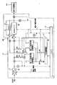
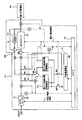
- FIG. 1 is a circuit diagram showing a schematic configuration of a rapid charging apparatus according to Embodiment 1.
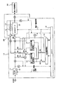
- FIG. 3 is a circuit diagram illustrating charging of a large-capacity storage battery in the rapid charging apparatus according to the first embodiment.
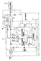
- FIG. 3 is a circuit diagram when charging the first storage battery for rapid charging in the rapid charging apparatus of the first embodiment. It is a circuit diagram when charging the 2nd storage battery for quick charge in the quick charge apparatus of Embodiment 1.
- FIG. FIG. 3 is a circuit diagram when charging a power storage battery via a buffer resistor in the quick charging device of the first embodiment.
- FIG. 3 is a circuit diagram when charging a power storage battery via a DC / DC converter in the rapid charging apparatus of the first embodiment.
- FIG. 3 is a circuit diagram when charging a power storage battery without passing through a buffer resistor and a DC / DC converter in the quick charging device of the first embodiment.
- FIG. 3 is a circuit diagram when charging the power storage battery by switching from the first rapid charge storage battery to the second rapid charge storage battery in the quick charge device of the first embodiment.
- FIG. 3 is a voltage and current curve diagram showing discharge characteristics in the rapid charging apparatus of the first embodiment. It is a circuit diagram when charging the 1st storage battery for quick charging from a high capacity
- FIG. It is a circuit diagram when charging the 2nd storage battery for quick charging from a high capacity
- FIG. 1 is a circuit diagram showing a schematic configuration of the rapid charging apparatus according to the first embodiment.
- a rapid charging apparatus 10 shown in the figure is an apparatus for rapidly charging a power storage battery 20 mounted on, for example, an electric vehicle.
- an AC / DC converter 11 connected to an AC 200V commercial power source, a charging / discharging speed, and the like.
- First and second quick charge storage batteries 12 and 13 storage battery
- a large capacity storage battery 14 having a larger electric capacity than that of the first and second quick charge storage batteries 12 and 13 and a slow charge / discharge rate
- a DC / DC converter 15 connected to the AC / DC converter 11, a controller 16 for controlling the AC / DC converter 11 and the DC / DC converter 15, and switches SW1 to SW8 for switching a current flow in the apparatus 10.
- a buffer resistor R1 inserted between the switch SW8 and the output terminal of the DC / DC converter 15, and the voltage in the device 10 Voltmeters V1 to V4 and ammeters A1 to A4 for measuring currents are provided.
- the buffer resistor R1 described above is a resistor for suppressing an excessive current that flows due to a potential difference with the device 10 when the power storage battery 20 is charged.
- the AC / DC converter 11 has a function of converting an alternating voltage into a direct current and stepping up and down the output based on an instruction from the controller 16.
- the DC / DC converter 15 has a function of increasing / decreasing the DC voltage based on an instruction from the controller 16.
- lithium ion batteries are used for the first and second quick charge storage batteries 12 and 13 and the large capacity storage battery 14.
- an electric double layer capacitor having a high charge / discharge rate can be used.
- the controller 16 uses the switches SW1 to SW8 based on the measurement information measured by the voltmeters V1 to V4 and the ammeters A1 to A4 and, for example, CAN communication input when the power storage battery 20 of the electric vehicle is connected. Open / close control is performed. Further, the controller 16 performs voltage / current control of the AC / DC converter 11 and voltage / current control of the DC / DC converter 15 as described above.
- the operation of the quick charging apparatus 10 configured as described above will be described with reference to FIGS.
- the controller 16 detects a night time when the electricity rate is low by using its own timer function
- the controller 16 detects whether or not the remaining capacity of the large-capacity storage battery 14 is fully charged by measuring the terminal voltage. If it is determined that the controller 16 is not fully charged, the controller 16 connects the AC / DC converter 11 and the large-capacity storage battery 14 as shown by the thick line in FIG. ) To charge the large-capacity storage battery 14.
- charging is performed by a method suitable for the battery used for the large-capacity storage battery 14 such as a constant voltage constant current method.
- Charge control in accordance with the remaining battery level is performed by the controller 16. Since the large-capacity storage battery 14 has a large capacity, for example, it is charged over a long time such as overnight.
- the controller 16 measures the remaining charge amount of the first quick-charge storage battery 12 in the same manner. To charge.
- the controller 16 connects the AC / DC converter 11 and the first quick charge storage battery 12 as shown by a bold line in FIG. 3, and then, at a voltage and current suitable for the first quick charge storage battery 12.
- the AC / DC converter 11 is controlled so that charging is performed.
- the charging of the first rapid charging storage battery 12 is completed in a shorter time than the charging of the large capacity storage battery 14, for example, from several minutes to about an hour.
- the controller 16 similarly determines the remaining amount of the second rapid charging storage battery 13, and when it is determined that charging is necessary, the thick line in FIG. As shown, the output terminal of the AC / DC converter 11 and the second rapid charging storage battery 13 are connected by switching the switch SW6, and the second rapid charging storage battery 13 is charged.
- the controller 16 detects reception of CAN communication from the electric vehicle after the charging of the first and second quick-charge storage batteries 12 and 13 and the large-capacity storage battery 14 is completed, the controller 16 powers the apparatus 10 and the electric vehicle. It is determined that the storage battery 20 is connected. Then, the controller 16 reads the power (voltage, current) necessary for the power storage battery 20 included in the CAN communication and starts charging. First, as shown by a thick line in FIG. 5, the controller 16 connects the first quick-charge storage battery 12 and the large-capacity storage battery 14 in series, and connects the switch SW8 to the buffer resistor R1 side to The storage battery 20 is charged.
- the voltage of the large-capacity storage battery 14 is V1 and the voltage of the first rapid charging storage battery 12 is V2 ( ⁇ V1)
- the voltage V1 + V2 is applied to the power storage battery 20 as shown in FIG.
- the voltage is gradually lowered as the charging progresses.
- the power storage battery 20 is charged from only two storage batteries, the efficiency is high and a stable charging operation is possible.
- the controller 16 6 controls the DC / DC converter 15 so as to obtain a current or voltage necessary for charging the power storage battery 20 to charge the power storage battery 20.
- the controller 16 may change the switch SW8 to a DC / DC converter as shown in FIG.
- the power storage battery 20 is directly charged without going through the buffer resistor R1 and the DC / DC converter 15.
- While the controller 16 is repeatedly charging the power storage battery 20, when the power of the first quick charge storage battery 12 becomes equal to or lower than the power required for charging, that is, the voltage V2 of the storage battery 12 changes to the time t. For example, when it becomes almost zero with the passage of time, as shown by a thick line in FIG. 8, the first rapid charge storage battery 12 is disconnected from the large capacity storage battery 14 and the second rapid charge storage battery 13 which is the next storage battery. And the large-capacity storage battery 14 are connected in series. Then, the controller 16 adds the voltage V3 of the second quick charge storage battery 13 to the voltage V1 of the large capacity storage battery 14, and similarly to the case where the first quick charge storage battery 12 is used, the power storage battery 20 is used. To charge.
- FIGS. 5 to 7 the voltage difference between the power storage battery 20 due to the connection of the first or second quick charge storage batteries 12 and 13 and the large capacity storage battery 14, the characteristics of the power storage battery 20, etc.
- the switch SW8 By switching the switch SW8, it is possible to select the connection of the buffer resistor R1, the connection of the DC / DC converter 15, or the direct connection.
- the time change of the charging voltage in this case is shown in FIG.
- FIG. 9A shows an example in which the voltage V3 of the second quick charge storage battery 13 is V3 ⁇ V1.
- the controller 16 controls the DC / DC converter 15 so that the voltage V ⁇ b> 1 of the large-capacity storage battery 14 is directly supplied to the power storage battery 20 via the DC / DC converter 15.
- the voltage V ⁇ b> 1 of the large capacity storage battery 14 becomes substantially constant and is supplied to the power storage battery 20 via the DC / DC converter 15.
- the current i at the time of charging is as shown in FIG. That is, until the electric capacities of the first and second quick charge storage batteries 12 and 13 become substantially zero, the first quick charge storage battery 12 and the large capacity storage battery 14 or the second quick charge storage battery 13 are used.
- the power storage battery 20 is charged using the large-capacity storage battery 14.
- the current required by the power storage battery 20 is supplied using only the large capacity storage battery 14 and continued. Can be charged.
- the controller 16 charges the first and second quick charge storage batteries 12 and 13 using the power of the large capacity storage battery 14 by the following method. First, as shown by a thick line in FIG. 10, the controller 16 connects the switch SW8 to the output side of the DC / DC converter 15, and connects the large capacity storage battery 14 and the first quick charge storage battery 12 to the DC / DC converter 15. Connect through.
- the controller 16 controls the DC / DC converter 15 so that electric power (voltage, current) necessary for charging the first rapid charging storage battery 12 is supplied from the large-capacity storage battery 14 with an appropriate current and voltage. Control.
- the controller 16 switches the connection with the large capacity storage battery 14 to the second quick charge storage battery 13 as shown by a thick line in FIG.
- the DC / DC converter 15 is controlled so that electric power (voltage, current) necessary for charging the second rapid charging storage battery 13 is supplied from the large-capacity storage battery 14.
- the charging operation described with reference to FIGS. 5 to 8 can be performed again. This is because the electric capacities of the first and second quick charge storage batteries 12 and 13 are smaller than that of the large capacity storage battery 14.
- the controller 16 charges the large-capacity storage battery 14 by the method shown in FIG. When such a state occurs during the daytime period, charging is performed without using nighttime power to prepare for the next charging of the power storage battery 20.
- the power storage battery 20 when charging the power storage battery 20 of the electric vehicle, the power storage battery 20 is charged by connecting the large-capacity storage battery 14 and the first rapid charge storage battery 12 in series. To do. When the electric capacity of the first rapid charging storage battery 12 becomes substantially zero due to the charging, the large capacity storage battery 14 and the second rapid charging storage battery 13 are connected in series to charge the power storage battery 20. Further, when the electric capacity of the second quick charge storage battery 13 becomes almost zero, the power storage battery 20 is charged only from the large capacity storage battery 14.
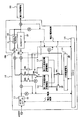
- FIG. 12 is a circuit diagram when charging the first rapid charging storage battery and charging the power storage battery with the second rapid charging storage battery and the large-capacity storage battery in the rapid charging apparatus of the second embodiment.
- the quick charging apparatus 10 that operates mainly by storing nighttime power in the large-capacity storage battery 20 has been described.
- the second quick charge storage battery 13 is connected in series with the large capacity storage battery 20 to charge the power storage battery 20.
- the auxiliary charging of the first rapid charging storage battery 12 whose remaining amount becomes zero can be performed only while the power storage battery 20 is not connected.
- the second quick charge storage battery 13 is connected in series with the large capacity storage battery 20 to provide a power storage battery.
- the AC / DC converter 11 can be used to perform supplementary charging to the first rapid charging storage battery 12.
- the connection between the first and second quick charge storage batteries 12 and 13 and the AC / DC converter 11 and the connection to the DC / DC converter 15 are also performed. Both of the switching are switched by the switch SW6. However, in the second embodiment, as shown in FIG. 12, the portion is switched separately by the two switching switches SW6 and SW6-1.
- the remaining amount of the first rapid charging storage battery 12 is almost zero, and the second rapid charging storage battery 13 and the large capacity storage battery 20 are used for power.
- the quick storage battery 20 had to wait while the remaining amount was almost zero.
- the AC / DC converter 11 and the first quick charge storage battery 12 are connected in series by switching the changeover switch SW6-1 while the power storage battery 20 is rapidly charged using the storage battery 13 and the large capacity storage battery 20.
- the power storage battery 20 when the power storage battery 20 is connected to the device 10 when the remaining amount of the second rapid charge storage battery 13 is substantially zero, the first rapid charge storage battery 12 and the large capacity While the storage battery 20 is used for quick charging to the power storage battery 20, supplementary charging from the AC / DC converter 11 to the second rapid charging storage battery 13 can be performed.
- the daytime power is used instead of the nighttime power, but since the capacity of each of the quick charging storage batteries 12 and 13 is small, the amount of charging power is small compared to the large capacity storage battery 14, Even if charging is performed using electric power in the daytime, it is possible to prevent an increase in electricity charges. Also in the second embodiment, the operations shown in FIGS. 2 to 8 in the first embodiment can be similarly performed.
- the second quick charge storage battery 13 and the large capacity storage battery 14 are used to store the power storage battery 20. Since the AC / DC converter 11 can be used for the auxiliary charging of the first rapid charging storage battery 12 at the same time, the power storage battery 20 can be continuously charged. .
- first and second embodiments it has been described that two quick-charge storage batteries are used. However, one or three or more quick-charge storage batteries may be used. Further, as the first and second quick charge storage batteries 12 and 13, quick charge storage batteries having different electric capacities and characteristics may be used in combination.
- an auxiliary power source (solar power generation, solar thermal power generation, wind power generation, geothermal power generation, etc.) is provided in addition to the commercial power source, and the first and second quick charging in the apparatus 10 are performed. It is also possible to supply power by connecting the storage batteries 12 and 13 in parallel. As a result, the amount of power received from the commercial power source can be reduced. In this case, in the case of facilities that generate alternating current, such as wind power generation, the batteries are supplied to the storage batteries 12 and 13 after being converted to direct current. 12 and 13.
- a commercial power source is used as the power source of the quick charging device 10, but the power source device is not limited to this, and any power source device that generates AC power, such as a private power generation facility, may be used. .
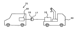
- FIG. 13 is a schematic diagram of a mobile charging apparatus in which the quick charging apparatus according to Embodiment 1 is mounted on a vehicle.
- the mobile charging device of the third embodiment is a vehicle in which the quick charging device 10 described in the first embodiment is mounted on a vehicle 30.
- the quick charging device 10 does not require input of AC power when charging the power storage battery 20, and therefore, when receiving a notification from the electric vehicle 21 that has run out of power storage battery 20 on the road and cannot move.
- the vehicle 30 travels to the site, connects the quick charging connector 17 and the connector 22 on the electric vehicle 21 side on the road, and charges the power storage battery 20 of the electric vehicle 21 in a short time.
- this mobile charging device can be charged in-vehicle and stand by in advance, the electric vehicle 21 that has become unable to move on the road can be urgently moved to a nearby power station or returned home. Necessary power charging can be performed in a short time.
Landscapes
- Engineering & Computer Science (AREA)
- Power Engineering (AREA)
- Mechanical Engineering (AREA)
- Transportation (AREA)
- Life Sciences & Earth Sciences (AREA)
- Sustainable Development (AREA)
- Sustainable Energy (AREA)
- General Chemical & Material Sciences (AREA)
- Electrochemistry (AREA)
- Chemical Kinetics & Catalysis (AREA)
- Chemical & Material Sciences (AREA)
- Manufacturing & Machinery (AREA)
- Charge And Discharge Circuits For Batteries Or The Like (AREA)
- Electric Propulsion And Braking For Vehicles (AREA)
- Secondary Cells (AREA)
Abstract
電気自動車の動力用蓄電池を充電する際の制御を容易にし、しかも急速充電用蓄電池を用いても小型でコストを抑えることのできる急速充電装置を提供する。急速充電装置10は、動力用蓄電池20への急速充電が可能な第1及び第2の急速充電用蓄電池12、13と、第1及び第2の急速充電用蓄電池12、13より電気容量の大きい大容量蓄電池14と、動力用蓄電池20を充電する際、前記第1の急速充電用蓄電池12と大容量蓄電池14とを直列に接続して、大容量蓄電池14の電力を第1の急速充電用蓄電池12の電力に加算して出力し、第1の急速充電用蓄電池12の電気容量がほぼゼロ状態になったときには、第2の急速充電用蓄電池13と大容量蓄電池14とを直列に接続して、大容量蓄電池14の電力を第2の急速充電用蓄電池13の電力に加算して出力するコントローラー16とを備えた。
Description
本発明は、例えば電気自動車に搭載された動力用蓄電池を充電する急速充電装置、及び急速充電装置を車両に搭載してなる移動式充電装置に関するものである。
近年、石油資源の枯渇や地球温暖化の対策として、電気エネルギーを駆動源とする電気自動車が市場に普及してきているが、電気自動車に対しても、通常の自動車給油と同等時間で充電をできる急速充電装置が求められている。
従来、急速充電できる装置として、例えば、大容量の設備用蓄電池を用意し、電気自動車への充電休止時に、その蓄電池を低電流で長時間をかけて充電しておき、電気自動車の動力用蓄電池を充電するときには設備用蓄電池から大電流を放電する充電装置がある(例えば、特許文献1参照)。
従来、急速充電できる装置として、例えば、大容量の設備用蓄電池を用意し、電気自動車への充電休止時に、その蓄電池を低電流で長時間をかけて充電しておき、電気自動車の動力用蓄電池を充電するときには設備用蓄電池から大電流を放電する充電装置がある(例えば、特許文献1参照)。
前述した従来の充電装置では、設備用蓄電池から大電流の直流電力を得て電気自動車の動力用蓄電池を急速放電する構成となっているが、その制御が複雑で、急速充電用蓄電池が高価であった。
本発明は、前記のような課題を解決するためになされたもので、電気自動車の動力用蓄電池を充電する際の制御を容易に、しかも急速充電用蓄電池を用いても小型でコストを抑えることのできる急速充電装置及び移動式充電装置を提供することを目的とする。
本発明は、前記のような課題を解決するためになされたもので、電気自動車の動力用蓄電池を充電する際の制御を容易に、しかも急速充電用蓄電池を用いても小型でコストを抑えることのできる急速充電装置及び移動式充電装置を提供することを目的とする。
本発明に係る急速充電装置は、負荷である動力用蓄電池への急速充電が可能な蓄電池と、蓄電池より電気容量の大きい大容量蓄電池と、動力用蓄電池を充電する際、蓄電池と大容量蓄電池とを直列に接続し、大容量蓄電池の電力を蓄電池の電力に加算して動力用蓄電池に供給するコントローラとを備えたものである。
本発明においては、動力用蓄電池を充電する際、蓄電池と大容量蓄電池とを直列に接続し、大容量蓄電池の電力を蓄電池の電力に加算して動力用蓄電池に供給するようにしたので、動力用蓄電池を充電する際の制御が容易になる。また、前述したように動力用蓄電池を充電する際、蓄電池の電力に大容量蓄電池の電力を加算しているので、電気容量の小さい急速充電用の蓄電池を用いることが可能になり、コストを抑えた急速充電装置を提供できる。
実施の形態1.
本実施の形態は、主に安価な夜間電力を本装置に内蔵された蓄電池に蓄積することにより車両等に急速充電を行うものである。
図1は実施の形態1に係る急速充電装置の概略構成を示す回路図である。
図中に示す急速充電装置10は、例えば電気自動車に搭載された動力用蓄電池20を急速充電するための装置で、例えば交流200Vの商用電源と接続されるAC/DCコンバーター11と、充放電速度が速い第1及び第2の急速充電用蓄電池12、13(蓄電池)と、第1及び第2の急速充電用蓄電池12、13より電気容量が大きく、充放電速度の遅い大容量蓄電池14と、AC/DCコンバーター11と接続されるDC/DCコンバーター15と、AC/DCコンバーター11及びDC/DCコンバーター15を制御するコントローラー16と、本装置10内の電流の流れを切り換えるためのスイッチSW1~SW8と、スイッチSW8とDC/DCコンバーター15の出力端との間に挿入された緩衝抵抗R1と、本装置10内の電圧と電流をそれぞれ測定するための電圧計V1~V4及び電流計A1~A4とを備えている。前述の緩衝抵抗R1は、動力用蓄電池20に充電する際に本装置10との電位差により流れる過大な電流を抑制するための抵抗である。
AC/DCコンバーター11は、交流電圧を直流に変換し、その出力をコントローラー16からの指示に基づいて昇降圧する機能を備えている。DC/DCコンバーター15は、コントローラー16からの指示に基づいて直流電圧を昇降圧する機能を有している。第1及び第2の急速充電用蓄電池12、13と大容量蓄電池14には、例えばリチウムイオン電池が使用されている。第1及び第2の急速充電用蓄電池12、13には、充放電速度の速い、例えば電気二重層キャパシタを用いることもできる。コントローラー16は、電圧計V1~V4と電流計A1~A4により測定された測定情報と電気自動車の動力用蓄電池20が接続されたときに入力される例えばCAN通信とに基づいて各スイッチSW1~SW8の開閉制御を行う。また、コントローラー16は、前述したように、AC/DCコンバーター11の電圧/電流制御、DC/DCコンバーター15の電圧/電流制御を行う。
次に、前記のように構成された急速充電装置10の動作について図2~図11を用いて説明する。先ず、図2~図4を用いて第1及び第2の急速充電用蓄電池12、13と大容量蓄電池14を充電するときの動作を説明する。
コントローラー16は、例えば、自己のタイマー機能により電気料金の安い夜間の時間を検知すると、大容量蓄電池14の残量が満充電になっているかどうかを端子電圧を計測する等の方法で検出する。コントローラー16は、満充電ではないと判定した場合には、図2に太線で示すように、AC/DCコンバーター11と大容量蓄電池14とを接続し、次いで、AC/DCコンバーター11を制御(電圧)して大容量蓄電池14に充電を行う。この場合、定電圧定電流方式等、大容量蓄電池14に使用した電池に適した方法で充電を行う。電池の残量に合わせた充電制御は、コントローラー16により行われる。大容量蓄電池14は容量が大きいため、例えば一晩等、長い時間をかけて充電が行われる。
コントローラー16は、例えば、自己のタイマー機能により電気料金の安い夜間の時間を検知すると、大容量蓄電池14の残量が満充電になっているかどうかを端子電圧を計測する等の方法で検出する。コントローラー16は、満充電ではないと判定した場合には、図2に太線で示すように、AC/DCコンバーター11と大容量蓄電池14とを接続し、次いで、AC/DCコンバーター11を制御(電圧)して大容量蓄電池14に充電を行う。この場合、定電圧定電流方式等、大容量蓄電池14に使用した電池に適した方法で充電を行う。電池の残量に合わせた充電制御は、コントローラー16により行われる。大容量蓄電池14は容量が大きいため、例えば一晩等、長い時間をかけて充電が行われる。
コントローラー16は、大容量蓄電池14への充電が終了すると、次に、第1の急速充電用蓄電池12の充電残量を同様に計測し、満充電ではないと判定した場合には、以下の方法により充電を行う。
コントローラー16は、図3に太線で示すように、AC/DCコンバーター11と第1の急速充電用蓄電池12とを接続し、その後、第1の急速充電用蓄電池12に適した電圧、電流にて充電が行われるようにAC/DCコンバーター11を制御する。第1の急速充電用蓄電池12への充電は、大容量蓄電池14への充電に比べて短い時間、例えば数分から一時間位で終了する。コントローラー16は、第1の急速充電用蓄電池12への充電が終了すると、同様に第2の急速充電用蓄電池13の残量を判定し、充電が必要と判定した場合には、図4に太線で示すように、AC/DCコンバーター11の出力端と第2の急速充電用蓄電池13とをスイッチSW6の切り替えにより接続し、第2の急速充電用蓄電池13への充電を行う。
コントローラー16は、図3に太線で示すように、AC/DCコンバーター11と第1の急速充電用蓄電池12とを接続し、その後、第1の急速充電用蓄電池12に適した電圧、電流にて充電が行われるようにAC/DCコンバーター11を制御する。第1の急速充電用蓄電池12への充電は、大容量蓄電池14への充電に比べて短い時間、例えば数分から一時間位で終了する。コントローラー16は、第1の急速充電用蓄電池12への充電が終了すると、同様に第2の急速充電用蓄電池13の残量を判定し、充電が必要と判定した場合には、図4に太線で示すように、AC/DCコンバーター11の出力端と第2の急速充電用蓄電池13とをスイッチSW6の切り替えにより接続し、第2の急速充電用蓄電池13への充電を行う。
次に、図5~図9を用いて動力用蓄電池20を充電するときの動作を説明する。
コントローラー16は、第1及び第2の急速充電用蓄電池12、13と大容量蓄電池14への充電が終了した後に、電気自動車からのCAN通信の受信を検知すると、本装置10と電気自動車の動力用蓄電池20とが接続されたと判定する。そして、コントローラー16は、そのCAN通信に含まれる動力用蓄電池20に必要な電力(電圧、電流)を読み込んで充電に入る。先ず、コントローラー16は、図5に太線で示すように、第1の急速充電用蓄電池12と大容量蓄電池14とを直列に接続すると共に、スイッチSW8を緩衝抵抗R1側に接続して、動力用蓄電池20への充電を行う。ここで、大容量蓄電池14の電圧をV1、第1の急速充電用蓄電池12の電圧をV2(<V1)としたとき、図9(a)に示すようにV1+V2の電圧が動力用蓄電池20に供給され、充電の進行とともに徐々に電圧が低下する。
この場合、2台の蓄電池のみから動力用蓄電池20への充電を行っているために効率が高く、安定な充電動作が可能である。
また、大容量蓄電池14と第1の急速充電用蓄電池12の加算電圧と動力用蓄電池20の電圧が大きく異なる等の理由で緩衝抵抗R1を経由して充電することができない場合には、コントローラー16は、図6に示すように、スイッチSW8をDC/DCコンバーター15の入力側に接続し、大容量蓄電池14と第1の急速充電用蓄電池12の加算電圧をDC/DCコンバーター15に入力させる。そして、コントローラー16は、動力用蓄電池20の充電に必要な電流あるいは電圧となるように、DC/DCコンバーター15を制御し、動力用蓄電池20に充電を行う。
この場合でも、第1の急速充電用蓄電池12と大容量蓄電池14を直列に接続しているため、動力用蓄電池20を充電するためのDC/DCコンバーター15での電圧調整は小さな電圧で済むため、DC/DCコンバーター15での損失は小さくなる。
この場合でも、第1の急速充電用蓄電池12と大容量蓄電池14を直列に接続しているため、動力用蓄電池20を充電するためのDC/DCコンバーター15での電圧調整は小さな電圧で済むため、DC/DCコンバーター15での損失は小さくなる。
また、動力用蓄電池20の特性及び電圧、大容量蓄電池14および第1もしくは第2の急速充電用蓄電池の電圧状況によっては、コントローラー16は、図7に示すように、スイッチSW8をDC/DCコンバーター15の出力側に接続して、緩衝抵抗R1及びDC/DCコンバーター15を経由することなく、直接に動力用蓄電池20の充電を行う。
コントローラー16は、動力用蓄電池20への充電を繰り返し行っているうちに、第1の急速充電用蓄電池12の電力が充電に必要な電力以下になると、つまり、その蓄電池12の電圧V2が時間tの経過に伴って例えばほぼゼロになると、図8に太線で示すように、第1の急速充電用蓄電池12を大容量蓄電池14から切り離すと共に、次の蓄電池である第2の急速充電用蓄電池13と大容量蓄電池14とを直列に接続する。そして、コントローラー16は、大容量蓄電池14の電圧V1に第2の急速充電用蓄電池13の電圧V3を加算し、前述の第1の急速充電用蓄電池12を用いた場合と同様に動力用蓄電池20への充電を行う。
この場合も、図5~図7と同様に、第1又は第2の急速充電用蓄電池12、13と大容量蓄電池14の接続による動力用蓄電池20との電圧差、動力用蓄電池20の特性等により、スイッチSW8を切り替えて、緩衝抵抗R1の接続、DC/DCコンバーター15の接続、直接接続の選択が可能である。
この場合の充電電圧の時間変化を図9(a)に示す。第1の急速充電用電池12の電圧低下に伴って充電電圧は一旦低下するが、第2の急速充電用蓄電池13の電圧V3に切り替える事により再度電圧が上昇して充電を再開する。図9(a)では、第2の急速充電用蓄電池13の電圧V3がV3<V1である場合を例に示す。
この場合も、図5~図7と同様に、第1又は第2の急速充電用蓄電池12、13と大容量蓄電池14の接続による動力用蓄電池20との電圧差、動力用蓄電池20の特性等により、スイッチSW8を切り替えて、緩衝抵抗R1の接続、DC/DCコンバーター15の接続、直接接続の選択が可能である。
この場合の充電電圧の時間変化を図9(a)に示す。第1の急速充電用電池12の電圧低下に伴って充電電圧は一旦低下するが、第2の急速充電用蓄電池13の電圧V3に切り替える事により再度電圧が上昇して充電を再開する。図9(a)では、第2の急速充電用蓄電池13の電圧V3がV3<V1である場合を例に示す。
さらに、コントローラー16は、動力用蓄電池20への充電を繰り返し行っているうちに、前記と同様に第2の急速充電用蓄電池13の電圧V3が時間tの経過に伴ってほぼゼロになったことを検知した場合には、スイッチSW1、SW5をオフすると共に、スイッチSW6をオフ(N)にし、スイッチSW3、SW4をオンする(電流経路図示せず)。次いで、コントローラー16は、大容量蓄電池14の電圧V1がDC/DCコンバーター15を経由して直接動力用蓄電池20に供給されるように、DC/DCコンバーター15を制御する。
この場合は、図9(a)に示すように大容量蓄電池14の電圧V1がほぼ一定となってDC/DCコンバータ15を経由して動力用蓄電池20に供給される。この充電時の電流iは、図9(b)に示すようになる。つまり、第1及び第2の急速充電用蓄電池12,13の電気容量がほぼゼロになるまでの間は、第1の急速充電用蓄電池12と大容量蓄電池14あるいは第2の急速充電用蓄電池13と大容量蓄電池14を用いて動力用蓄電池20への充電を行う。また、第1及び第2の急速充電用蓄電池12、13がともに残量がなくなった場合には、大容量蓄電池14のみを用いて、動力用蓄電池20の必要とする電流を供給し、継続して充電を行うことができる。
この場合は、図9(a)に示すように大容量蓄電池14の電圧V1がほぼ一定となってDC/DCコンバータ15を経由して動力用蓄電池20に供給される。この充電時の電流iは、図9(b)に示すようになる。つまり、第1及び第2の急速充電用蓄電池12,13の電気容量がほぼゼロになるまでの間は、第1の急速充電用蓄電池12と大容量蓄電池14あるいは第2の急速充電用蓄電池13と大容量蓄電池14を用いて動力用蓄電池20への充電を行う。また、第1及び第2の急速充電用蓄電池12、13がともに残量がなくなった場合には、大容量蓄電池14のみを用いて、動力用蓄電池20の必要とする電流を供給し、継続して充電を行うことができる。
次に、第1及び第2の急速充電用蓄電池12、13がともに残量がなくなり、動力用蓄電池20が接続されていない場合に、大容量蓄電池20から第1及び第2の急速充電用蓄電池12、13に補充電を行う場合の動作を図10及び図11を用いて説明する。
コントローラー16は、動力用蓄電池20への充電が終了すると、以下の方法により、大容量蓄電池14の電力を用いて第1及び第2の急速充電用蓄電池12、13の充電を行う。
先ず、コントローラー16は、図10に太線で示すように、スイッチSW8をDC/DCコンバーター15の出力側に接続し、大容量蓄電池14と第1の急速充電用蓄電池12とをDC/DCコンバーター15を介して接続する。そして、コントローラー16は、適切な電流、電圧にて第1の急速充電用蓄電池12の充電に必要な電力(電圧、電流)が大容量蓄電池14から供給されるように、DC/DCコンバーター15を制御する。
この制御により第1の急速充電用蓄電池12が満充電状態になると、コントローラー16は、図11に太線で示すように、大容量蓄電池14との接続を第2の急速充電用蓄電池13に切り替えて、第2の急速充電用蓄電池13の充電に必要な電力(電圧、電流)が大容量蓄電池14から供給されるように、DC/DCコンバーター15を制御する。
これにより、図5~図8で説明した充電動作を再度実施することが可能となる。これは、第1及び第2の急速充電用蓄電池12,13の電気容量が大容量蓄電池14と比べ小さいからである。
コントローラー16は、図5~図11に示す充放電を繰り返すうちに、大容量蓄電池14の電気容量が所定量まで低下したときには、図2に示した方法により大容量蓄電池14への充電を行う。昼の時間帯にこのような状態になった場合には、夜間電力を使用せずに充電を行い、次の動力用蓄電池20への充電に備える。
以上のように実施の形態1においては、電気自動車の動力用蓄電池20を充電する際に、大容量蓄電池14と第1の急速充電用蓄電池12とを直列に接続して動力用蓄電池20を充電する。その充電により第1の急速充電用蓄電池12の電気容量がほぼゼロになったときには、大容量蓄電池14と第2の急速充電用蓄電池13とを直列に接続して動力用蓄電池20を充電する。さらに、第2の急速充電用蓄電池13の電気容量がほぼゼロになったときには、大容量蓄電池14のみから動力用蓄電池20を充電する。
これにより、電気自動車の動力用蓄電池20を充電するときの制御が容易になると同時に、電力損失を削減した効率の良い充電が可能である。また、前述したように動力用蓄電池20を充電する際、第1の急速充電用蓄電池12の電力に大容量蓄電池14の電力を加算しているので、電気容量の小さい急速充電用蓄電池を用いることが可能になり、コストを抑えた急速充電装置10を提供できる。
実施の形態2.
次に、実施の形態2について図12を用いて説明する。
図12は実施の形態2の急速充電装置において第1の急速充電用蓄電池への充電及び第2の急速充電用蓄電池と大容量蓄電池とで動力用蓄電池を充電しているときの回路図である。
前述した実施の形態1では、主に夜間の電力を大容量蓄電池20に蓄えて動作する急速充電装置10について説明した。しかし、第1の急速充電用蓄電池12の残量がほぼゼロとなった場合には、第2の急速充電用蓄電池13を大容量蓄電池20と直列に接続して動力用蓄電池20への充電を継続して行えるものの、残量がゼロとなった第1の急速充電用蓄電池12の補充電を行えるのは動力用蓄電池20が接続されていない間だけであるという課題がある。
そこで、実施の形態2では、第1の急速充電用蓄電池12の残量がほぼゼロとなった場合に、第2の急速充電用蓄電池13を大容量蓄電池20と直列に接続して動力用蓄電池20への充電を実施すると同時に、AC/DCコンバーター11を用いて第1の急速充電用蓄電池12への補充電を行えるようにしたものである。
実施の形態1では、図1に示したように、第1及び第2の急速充電用蓄電池12、13とAC/DCコンバーター11への接続の切り替えと、同じくDC/DCコンバーター15への接続の切り替えを共にスイッチSW6で切り替えているが、実施の形態2では、図12に示すように、その部分を2個の切替スイッチSW6、SW6−1で別々に切り替える構成となっている。
これにより、例えば図8に示したように、実施の形態1では第1の急速充電用蓄電池12の残量がほぼゼロで、第2の急速充電用蓄電池13と大容量蓄電池20を用いて動力用蓄電池20への急速充電を行っている場合、第1の急速充電用蓄電池12は残量がほぼゼロのまま待機せざるを得なかったが、図12に示すように、第2の急速充電用蓄電池13と大容量蓄電池20を用いて動力用蓄電池20への急速充電を行っている間に、切替スイッチSW6−1の切り替えによりAC/DCコンバーター11と第1の急速充電用蓄電池12を直列に接続してAC/DCコンバーター11から第1の急速充電用蓄電池12に補充電を行う。また逆に、第2の急速充電用蓄電池13の残量がほぼゼロ状態のときに、本装置10に動力用蓄電池20が接続された場合には、第1の急速充電用蓄電池12と大容量蓄電池20を用いて動力用蓄電池20への急速充電を行うと共に、AC/DCコンバーター11から第2の急速充電用蓄電池13への補充電を行うことができる。
この場合は夜間の電力ではなく、昼間の電力を用いることになるが、各急速充電用蓄電池12、13の容量は小さいために、充電電力量は大容量蓄電池14と比べて少量であるため、昼間の電力を用いて充電を行っても電気料金の高騰を防ぐことが可能である。
実施の形態2においても、実施の形態1において図2~図8に示した各動作は同様に実施可能である。
実施の形態2においても、実施の形態1において図2~図8に示した各動作は同様に実施可能である。
このように実施の形態2においては、第1の急速充電用蓄電池12の残量がほぼゼロとなった場合に、第2の急速充電用蓄電池13と大容量蓄電池14を用いて動力用蓄電池20への急速充電を行うと同時に、AC/DCコンバーター11を用いて第1の急速充電用蓄電池12への補充電が可能であるため、さらに連続的に動力用蓄電池20への充電が可能となる。
なお、実施の形態1、2では、急速充電用蓄電池を2台用いたことを述べたが、1台あるいは3台以上の急速充電用蓄電池を用いるようにしてもよい。また、第1及び第2の急速充電用蓄電池12、13として、電気容量、特性の異なる急速充電用蓄電池を組み合わせて使用しても良い。
また、実施の形態1、2においては、商用電源とは別に補助電源(太陽光発電、太陽熱発電、風力発電、地熱発電など)を設け、本装置10内の第1及び第2の急速充電用蓄電池12、13に並列に接続することにより給電することも可能である。これにより、商用電源からの受電量を軽減することが可能となる。この場合、風力発電等、交流を発電する設備の場合には直流に変換後に各蓄電池12、13に供給し、太陽光発電等、直流を発電する設備の場合には電圧を変換した後に各蓄電池12、13に供給する。
また、実施の形態1、2では、急速充電装置10の電源として商用電源としたが、これに限定されるものではなく、自家発電設備等、交流電力を発電する電源装置であれば何れでも良い。
実施の形態3.
図13は実施の形態1の急速充電装置を車両に搭載して示す移動式充電装置の模式図である。
実施の形態3の移動式充電装置は、図13に示すように、実施の形態1で説明した急速充電装置10を車両30に搭載したものである。本急速充電装置10は、動力用蓄電池20への充電の際に交流電力の入力を必要としないため、路上で動力用蓄電池20を使い果たして動けなくなった電気自動車21からの連絡を受けた場合に、前述の車両30が現地に赴き、路上にて急速充電用コネクタ17と電気自動車21側のコネクタ22とを接続して短時間に電気自動車21の動力用蓄電池20を充電する。
この移動式充電装置は、予め車載上で充電されて待機することが可能であるため、路上で動けなくなった電気自動車21を緊急避難的に近くの給電所へ移動させたり、自宅に帰るのに必要な電力充電を短時間に行うことができる。
10 急速充電装置、11 AC/DCコンバーター、12 第1の急速充電用蓄電池、13 第2の急速充電用蓄電池、14 大容量蓄電池、15 DC/DCコンバーター、16 コントローラー、17 急速充電用コネクタ、20 動力用蓄電池、21 電気自動車、22 コネクタ、30 車両。
Claims (10)
- 負荷である動力用蓄電池への急速充電が可能な蓄電池と、
前記蓄電池より電気容量の大きい大容量蓄電池と、
動力用蓄電池を充電する際、前記蓄電池と前記大容量蓄電池とを直列に接続し、前記大容量蓄電池の電力を前記蓄電池の電力に加算して動力用蓄電池に供給するコントローラーと
を備えたことを特徴とする急速充電装置。 - 動力用蓄電池と接続されるDC/DCコンバーターを備え、
前記コントローラーは、加算した電力により動力用蓄電池を充電しているときに、前記蓄電池の電力が充電に必要な電力以下になると、前記大容量蓄電池のみの電力が前記DC/DCコンバーターを経由して動力用蓄電池に供給されるように、前記DC/DCコンバーターを制御することを特徴とする請求項1記載の急速充電装置。 - 前記蓄電池を複数備え、
前記コントローラーは、動力用蓄電池への充電により、前記大容量蓄電池と直列に接続された蓄電池の電力が充電に必要な電力以下になったときには、次の蓄電池と前記大容量蓄電池とを直列に接続することを特徴とする請求項1又は2記載の急速充電装置。 - 交流電源と接続されるAC/DCコンバーターを備え、
前記コントローラーは、次の蓄電池と前記大容量蓄電池とを直列に接続して動力用蓄電池への充電を行っているときに、充電に必要な電力以下となった蓄電池をAC/DCコンバーターと接続して、その蓄電池に電力が供給されるように、前記AC/DCコンバーターを制御することを特徴とする請求項1乃至3の何れかに記載の急速充電装置。 - 前記コントローラーは、動力用蓄電池への充電休止時に、前記大容量蓄電池の電力が前記DC/DCコンバーターを経由して前記蓄電池に充電されるように、そのDC/DCコンバーターを制御することを特徴とする請求項2乃至4の何れかに記載の急速充電装置。
- 動力用蓄電池と接続される過大電流抑制用の緩衝抵抗を備え、
前記コントローラーは、加算した電力により動力用蓄電池を充電する際、その電力を前記緩衝抵抗を経由させて動力用蓄電池に供給することを特徴とする請求項1乃至5の何れかに記載の急速充電装置。 - 前記コントローラーは、加算した電力により動力用蓄電池を充電する際、その電力が前記DC/DCコンバーターを経由して動力用蓄電池に供給されるように、そのDC/DCコンバーターを制御することを特徴とする請求項2乃至6の何れかに記載の急速充電装置。
- 前記コントローラは、動力用蓄電池への充電休止時に、前記AC/DCコンバーターから前記大容量蓄電池に電力が充電されるように、そのAC/DCコンバーターを制御することを特徴とする請求項4乃至7の何れかに記載の急速充電装置。
- 前記コントローラーは、動力用蓄電池への充電休止時に、前記AC/DCコンバーターから前記蓄電池に電力が充電されるように、そのAC/DCコンバーターを制御することを特徴とする請求項4乃至8の何れかに記載の急速充電装置。
- 請求項1乃至9の何れかに記載の急速充電装置を車両に備えたことを特徴とする移動式充電装置。
Priority Applications (3)
| Application Number | Priority Date | Filing Date | Title |
|---|---|---|---|
| CN2011800101331A CN102782976A (zh) | 2010-02-19 | 2011-02-18 | 快速充电装置以及移动式充电装置 |
| US13/579,082 US20130049676A1 (en) | 2010-02-19 | 2011-02-18 | Quick charging device and mobile charging apparatus |
| EP11744826.6A EP2538518A4 (en) | 2010-02-19 | 2011-02-18 | FAST CHARGER AND MOBILE LOADING DEVICE |
Applications Claiming Priority (2)
| Application Number | Priority Date | Filing Date | Title |
|---|---|---|---|
| JP2010034805 | 2010-02-19 | ||
| JP2010-034805 | 2010-02-19 |
Publications (1)
| Publication Number | Publication Date |
|---|---|
| WO2011102543A1 true WO2011102543A1 (ja) | 2011-08-25 |
Family
ID=44483123
Family Applications (1)
| Application Number | Title | Priority Date | Filing Date |
|---|---|---|---|
| PCT/JP2011/054203 WO2011102543A1 (ja) | 2010-02-19 | 2011-02-18 | 急速充電装置及び移動式充電装置 |
Country Status (5)
| Country | Link |
|---|---|
| US (1) | US20130049676A1 (ja) |
| EP (1) | EP2538518A4 (ja) |
| JP (1) | JP5016121B2 (ja) |
| CN (1) | CN102782976A (ja) |
| WO (1) | WO2011102543A1 (ja) |
Cited By (2)
| Publication number | Priority date | Publication date | Assignee | Title |
|---|---|---|---|---|
| EP2612786A3 (en) * | 2012-01-09 | 2016-12-07 | Tata Technologies Pte Ltd | Buddy charging for electric vehicles |
| EP3604020A1 (fr) * | 2012-01-23 | 2020-02-05 | Commissariat à l'Energie Atomique et aux Energies Alternatives | Gestion combinée de deux sources de tension |
Families Citing this family (27)
| Publication number | Priority date | Publication date | Assignee | Title |
|---|---|---|---|---|
| JP2012034554A (ja) * | 2009-08-21 | 2012-02-16 | Jfe Engineering Corp | 急速充電装置 |
| KR101245277B1 (ko) * | 2010-06-08 | 2013-03-19 | 주식회사 엘지화학 | 배터리 팩 충전 시스템 및 방법 |
| JP5679063B2 (ja) * | 2011-08-30 | 2015-03-04 | トヨタ自動車株式会社 | 車両 |
| KR20130046234A (ko) * | 2011-10-27 | 2013-05-07 | 삼성에스디아이 주식회사 | 배터리 팩 및 이의 제어 방법 |
| DE112012005145T5 (de) * | 2011-12-08 | 2014-10-16 | Institute For Energy Application Technologies Co., Ltd. | Schnelllade-Stromversorgungssystem |
| EP2647522B1 (de) * | 2012-04-03 | 2020-01-22 | Enrichment Technology Company Ltd. | Stromtankstelle mit Schnellladestationen |
| WO2013179930A1 (ja) * | 2012-05-28 | 2013-12-05 | 兵庫ベンダ工業株式会社 | バッテリ装置、情報処理装置、およびそれらの制御方法ならびに制御プログラム |
| CN104124741A (zh) * | 2013-04-29 | 2014-10-29 | 鸿富锦精密电子(天津)有限公司 | 定时充电电路 |
| CN106132761B (zh) * | 2014-03-27 | 2018-10-09 | 本田技研工业株式会社 | 电动车辆以及车辆供电方法 |
| US10333323B2 (en) * | 2015-03-24 | 2019-06-25 | Horizon Hobby, LLC | Systems and methods for battery charger with internal power source |
| DE102015211683A1 (de) * | 2015-06-24 | 2016-12-29 | WhiteRock Aktiengesellschaft | Verfahren zum Laden von Zielbatterien mit einem Pufferbatteriesystem |
| GB2537273B (en) * | 2015-10-16 | 2018-02-14 | Ford Global Tech Llc | A vehicle electrical system |
| KR101924520B1 (ko) | 2016-06-16 | 2018-12-03 | 주식회사 엘지화학 | 배터리 시스템 관리 장치 및 방법 |
| DE102016221829A1 (de) | 2016-11-08 | 2018-05-09 | Audi Ag | Energieversorgungsfahrzeug zum Versorgen eines elektrisch antreibbaren Kraftfahrzeugs mit elektrischer Energie |
| EP3600947B1 (en) * | 2017-03-24 | 2021-10-20 | The Noco Company | Electric vehicle (ev) fast recharge station and system |
| US11600996B2 (en) | 2017-03-24 | 2023-03-07 | The Noco Company | Electric vehicle (EV) fast recharge station and system |
| IT201700046501A1 (it) * | 2017-04-28 | 2018-10-28 | Alberto Chiesi | Rete di ricarica per veicoli elettrici |
| CN109463023B (zh) * | 2017-05-09 | 2022-07-08 | 合同会社崇朗环保系统 | 太阳能发电设备 |
| CN108565916A (zh) * | 2018-04-25 | 2018-09-21 | 爱驰汽车有限公司 | 一种电池包串联装置及其控制方法 |
| DE102018117157A1 (de) * | 2018-07-16 | 2020-01-16 | Still Gmbh | Batterieladeeinrichtung für Flurförderzeuge |
| IT201800021109A1 (it) | 2018-12-27 | 2020-06-27 | Ferrari Spa | Dispositivo di ricarica rapido per un veicolo con propulsione elettrica e provvisto di spintori a gas e relativo metodo di utilizzo |
| KR20210005396A (ko) * | 2019-07-04 | 2021-01-14 | 현대자동차주식회사 | 충전 장치 및 그 제어 방법 |
| CN110979092A (zh) * | 2019-11-07 | 2020-04-10 | 航天科工微电子系统研究院有限公司 | 一种特种车辆供电系统及其工作方法 |
| US20220024334A1 (en) * | 2020-07-23 | 2022-01-27 | Marscharge, Inc. | Decentralized reserved power charger |
| KR102308909B1 (ko) * | 2020-08-19 | 2021-10-05 | 주식회사 피앤에이 | 이동형 충전기 |
| JP7294286B2 (ja) | 2020-09-18 | 2023-06-20 | トヨタ自動車株式会社 | 充電器、及び車両 |
| US11855470B2 (en) * | 2021-09-23 | 2023-12-26 | Fluidity Power LLC | Mobile generator charging system and method |
Citations (7)
| Publication number | Priority date | Publication date | Assignee | Title |
|---|---|---|---|---|
| JPH05207668A (ja) | 1992-01-24 | 1993-08-13 | Nissan Motor Co Ltd | 充電装置 |
| JP2004274862A (ja) * | 2003-03-07 | 2004-09-30 | Sony Corp | 充電方法、充電回路およびそれを用いた充電装置 |
| JP2004328826A (ja) * | 2003-04-22 | 2004-11-18 | Fuji Heavy Ind Ltd | 充電装置及び充電方法 |
| JP2006020438A (ja) * | 2004-07-02 | 2006-01-19 | Nissan Motor Co Ltd | 充電スタンド |
| JP3123576U (ja) * | 2006-05-11 | 2006-07-20 | 伊藤 昇 | Evステーションシステム |
| JP2009268343A (ja) * | 2008-04-03 | 2009-11-12 | Panasonic Corp | 電源装置 |
| JP2010022108A (ja) * | 2008-07-09 | 2010-01-28 | Fuji Heavy Ind Ltd | 電源装置 |
Family Cites Families (13)
| Publication number | Priority date | Publication date | Assignee | Title |
|---|---|---|---|---|
| US4540929A (en) * | 1984-02-16 | 1985-09-10 | Energy Exchange Systems | Battery recharger |
| JPH03123576U (ja) * | 1990-03-26 | 1991-12-16 | ||
| US6268711B1 (en) * | 1999-05-05 | 2001-07-31 | Texas Instruments Incorporated | Battery manager |
| JP2001260718A (ja) * | 2000-03-16 | 2001-09-26 | Railway Technical Res Inst | 電鉄用直流電力供給設備 |
| US6377029B1 (en) * | 2000-04-26 | 2002-04-23 | Vector Manufacturing, Ltd. | Current regulated mobile battery booster |
| US20040201365A1 (en) * | 2001-04-05 | 2004-10-14 | Electrovaya Inc. | Energy storage device for loads having variable power rates |
| JP2003259508A (ja) * | 2002-02-26 | 2003-09-12 | Sanyo Electric Co Ltd | 電気自動車用の電源装置 |
| KR100675366B1 (ko) * | 2002-12-30 | 2007-01-29 | 주식회사 네스캡 | 전기에너지 저장장치 및 이의 충방전 방법 |
| US20060220610A1 (en) * | 2005-04-05 | 2006-10-05 | Kold Ban International, Inc. | Power management controller |
| CN101346849A (zh) * | 2005-12-28 | 2009-01-14 | 森幸信 | 无铅电池和使用其的车辆系统 |
| CN101150259B (zh) * | 2006-09-18 | 2010-05-12 | 比亚迪股份有限公司 | 电动车充电系统 |
| US20100039062A1 (en) * | 2008-08-18 | 2010-02-18 | Gong-En Gu | Smart charge system for electric vehicles integrated with alternative energy sources and energy storage |
| JP2012034554A (ja) * | 2009-08-21 | 2012-02-16 | Jfe Engineering Corp | 急速充電装置 |
-
2011
- 2011-02-16 JP JP2011030500A patent/JP5016121B2/ja not_active Expired - Fee Related
- 2011-02-18 EP EP11744826.6A patent/EP2538518A4/en not_active Withdrawn
- 2011-02-18 WO PCT/JP2011/054203 patent/WO2011102543A1/ja active Application Filing
- 2011-02-18 US US13/579,082 patent/US20130049676A1/en not_active Abandoned
- 2011-02-18 CN CN2011800101331A patent/CN102782976A/zh active Pending
Patent Citations (7)
| Publication number | Priority date | Publication date | Assignee | Title |
|---|---|---|---|---|
| JPH05207668A (ja) | 1992-01-24 | 1993-08-13 | Nissan Motor Co Ltd | 充電装置 |
| JP2004274862A (ja) * | 2003-03-07 | 2004-09-30 | Sony Corp | 充電方法、充電回路およびそれを用いた充電装置 |
| JP2004328826A (ja) * | 2003-04-22 | 2004-11-18 | Fuji Heavy Ind Ltd | 充電装置及び充電方法 |
| JP2006020438A (ja) * | 2004-07-02 | 2006-01-19 | Nissan Motor Co Ltd | 充電スタンド |
| JP3123576U (ja) * | 2006-05-11 | 2006-07-20 | 伊藤 昇 | Evステーションシステム |
| JP2009268343A (ja) * | 2008-04-03 | 2009-11-12 | Panasonic Corp | 電源装置 |
| JP2010022108A (ja) * | 2008-07-09 | 2010-01-28 | Fuji Heavy Ind Ltd | 電源装置 |
Non-Patent Citations (1)
| Title |
|---|
| See also references of EP2538518A4 |
Cited By (2)
| Publication number | Priority date | Publication date | Assignee | Title |
|---|---|---|---|---|
| EP2612786A3 (en) * | 2012-01-09 | 2016-12-07 | Tata Technologies Pte Ltd | Buddy charging for electric vehicles |
| EP3604020A1 (fr) * | 2012-01-23 | 2020-02-05 | Commissariat à l'Energie Atomique et aux Energies Alternatives | Gestion combinée de deux sources de tension |
Also Published As
| Publication number | Publication date |
|---|---|
| JP2011193716A (ja) | 2011-09-29 |
| US20130049676A1 (en) | 2013-02-28 |
| EP2538518A1 (en) | 2012-12-26 |
| CN102782976A (zh) | 2012-11-14 |
| JP5016121B2 (ja) | 2012-09-05 |
| EP2538518A4 (en) | 2014-09-17 |
Similar Documents
| Publication | Publication Date | Title |
|---|---|---|
| JP5016121B2 (ja) | 急速充電装置及び移動式充電装置 | |
| JP4954335B2 (ja) | 急速充電装置 | |
| US11021067B2 (en) | Electrically powered vehicle and control method for electrically powered vehicle | |
| EP2469682A1 (en) | Quick charging device | |
| US9937805B2 (en) | Battery charging system and charging method using same | |
| EP2369712A1 (en) | Battery charging apparatus | |
| US20100231164A1 (en) | Charging system for electric vehicle | |
| US20160347197A1 (en) | Electrical System and Method for Operating an Electrical System | |
| JP2018538774A (ja) | 電気自動車用駆動回路及びその制御方法 | |
| JP2012135154A (ja) | リチウムイオン二次電池の充電制御装置 | |
| KR101663991B1 (ko) | 하이브리드 충전장치 | |
| CN102709991A (zh) | 向至少一个负载供给功率的充电装置、系统和方法 | |
| WO2011105580A1 (ja) | 充電システム、充放電制御装置および充放電制御方法 | |
| JP2021093788A (ja) | 充電装置及び充電方法 | |
| KR101525727B1 (ko) | 배터리 충전식 컨버터 및 그것의 동작모드 전환 방법 | |
| JP7006572B2 (ja) | 車両用充電制御システム | |
| CN114454720A (zh) | 列车供电控制装置、系统以及方法 | |
| CN116601046A (zh) | 供电系统 | |
| WO2019093048A1 (ja) | 複合蓄電システム | |
| Jung et al. | Grid-connected electric vehicles charger station based on lithium polymer battery energy storage system | |
| JP2013157282A (ja) | 電源装置及びこれを備える車両並びに蓄電装置 | |
| US11760212B1 (en) | Electrical power generation and distribution | |
| US20210146789A1 (en) | Low voltage compensation system for micro electric vehicle | |
| JP2022155068A (ja) | 充放電管理システム | |
| JP2012253879A (ja) | 充電器及び充電方法 |
Legal Events
| Date | Code | Title | Description |
|---|---|---|---|
| WWE | Wipo information: entry into national phase |
Ref document number: 201180010133.1 Country of ref document: CN |
|
| 121 | Ep: the epo has been informed by wipo that ep was designated in this application |
Ref document number: 11744826 Country of ref document: EP Kind code of ref document: A1 |
|
| NENP | Non-entry into the national phase |
Ref country code: DE |
|
| WWE | Wipo information: entry into national phase |
Ref document number: 13579082 Country of ref document: US Ref document number: 2011744826 Country of ref document: EP |