WO2011102319A1 - ランキンサイクル装置 - Google Patents
ランキンサイクル装置 Download PDFInfo
- Publication number
- WO2011102319A1 WO2011102319A1 PCT/JP2011/053046 JP2011053046W WO2011102319A1 WO 2011102319 A1 WO2011102319 A1 WO 2011102319A1 JP 2011053046 W JP2011053046 W JP 2011053046W WO 2011102319 A1 WO2011102319 A1 WO 2011102319A1
- Authority
- WO
- WIPO (PCT)
- Prior art keywords
- pressure
- flow path
- drive shaft
- rankine cycle
- expander
- Prior art date
- Legal status (The legal status is an assumption and is not a legal conclusion. Google has not performed a legal analysis and makes no representation as to the accuracy of the status listed.)
- Ceased
Links
Images



Classifications
-
- F—MECHANICAL ENGINEERING; LIGHTING; HEATING; WEAPONS; BLASTING
- F01—MACHINES OR ENGINES IN GENERAL; ENGINE PLANTS IN GENERAL; STEAM ENGINES
- F01C—ROTARY-PISTON OR OSCILLATING-PISTON MACHINES OR ENGINES
- F01C1/00—Rotary-piston machines or engines
- F01C1/30—Rotary-piston machines or engines having the characteristics covered by two or more groups F01C1/02, F01C1/08, F01C1/22, F01C1/24 or having the characteristics covered by one of these groups together with some other type of movement between co-operating members
- F01C1/34—Rotary-piston machines or engines having the characteristics covered by two or more groups F01C1/02, F01C1/08, F01C1/22, F01C1/24 or having the characteristics covered by one of these groups together with some other type of movement between co-operating members having the movement defined in group F01C1/08 or F01C1/22 and relative reciprocation between the co-operating members
- F01C1/344—Rotary-piston machines or engines having the characteristics covered by two or more groups F01C1/02, F01C1/08, F01C1/22, F01C1/24 or having the characteristics covered by one of these groups together with some other type of movement between co-operating members having the movement defined in group F01C1/08 or F01C1/22 and relative reciprocation between the co-operating members with vanes reciprocating with respect to the inner member
-
- F—MECHANICAL ENGINEERING; LIGHTING; HEATING; WEAPONS; BLASTING
- F01—MACHINES OR ENGINES IN GENERAL; ENGINE PLANTS IN GENERAL; STEAM ENGINES
- F01C—ROTARY-PISTON OR OSCILLATING-PISTON MACHINES OR ENGINES
- F01C13/00—Adaptations of machines or engines for special use; Combinations of engines with devices driven thereby
- F01C13/04—Adaptations of machines or engines for special use; Combinations of engines with devices driven thereby for driving pumps or compressors
-
- F—MECHANICAL ENGINEERING; LIGHTING; HEATING; WEAPONS; BLASTING
- F01—MACHINES OR ENGINES IN GENERAL; ENGINE PLANTS IN GENERAL; STEAM ENGINES
- F01C—ROTARY-PISTON OR OSCILLATING-PISTON MACHINES OR ENGINES
- F01C20/00—Control of, monitoring of, or safety arrangements for, machines or engines
- F01C20/28—Safety arrangements; Monitoring
-
- F—MECHANICAL ENGINEERING; LIGHTING; HEATING; WEAPONS; BLASTING
- F01—MACHINES OR ENGINES IN GENERAL; ENGINE PLANTS IN GENERAL; STEAM ENGINES
- F01K—STEAM ENGINE PLANTS; STEAM ACCUMULATORS; ENGINE PLANTS NOT OTHERWISE PROVIDED FOR; ENGINES USING SPECIAL WORKING FLUIDS OR CYCLES
- F01K13/00—General layout or general methods of operation of complete plants
- F01K13/02—Controlling, e.g. stopping or starting
Definitions
- the present invention applies a rotational force to a drive shaft of the rotating electrical machine by utilizing a rotating electrical machine functioning as at least a generator, a rotational speed control means for controlling the rotational speed of the rotating electrical machine, and a Rankine cycle working fluid.
- the present invention relates to a Rankine cycle device including an expander and a pump that sucks and discharges a Rankine cycle working fluid.
- the working fluid is overheated by heat from a heat exchanger, that is, a boiler that takes heat from cooling water that cools a heating element such as an engine and transfers it to the working fluid.
- a heat exchanger that is, a boiler that takes heat from cooling water that cools a heating element such as an engine and transfers it to the working fluid.
- the pressure on the downstream side of the pump is not always low. That is, even if the difference becomes equal to or less than a predetermined pressure, the working fluid in the cycle is not necessarily in a state where gas is mixed (cavitation) or in a state where all of the gas is gaseous. Therefore, the information on the difference between the pressure on the upstream side and the pressure on the downstream side of the pump cannot accurately determine whether the working fluid, that is, the refrigerant is insufficient, and the waste heat recovery efficiency is reduced.
- An object of the present invention is to appropriately grasp whether or not the Rankine cycle working fluid, that is, the pressure of the refrigerant is abnormal so as to stop the recovery of waste heat.
- the present invention relates to at least a rotating electrical machine that functions as a generator, an expander that applies a rotational force to a drive shaft of the rotating electrical machine using Rankine cycle working fluid, and an intake and discharge of Rankine cycle working fluid.
- a Rankine cycle device comprising a pump and rotation control means for controlling the rotation of the drive shaft, wherein the expander and the pump rotate together, is provided downstream of the pump.
- a pressure detecting means for detecting the pressure in the high pressure flow path upstream of the expander, a rotational speed grasping means for grasping the rotational speed of the drive shaft, and a rotational speed grasped by the rotational speed grasping means; Determining means for determining whether or not a set of the pressure detected by the pressure detecting means is within a preset allowable range of rotation speed versus pressure, and the rotation control means includes the set. That when the pressure is in the low pressure area than the allowable region of the revolution speed and pressure performs stop control to zero the rotational speed of the rotary electric machine.
- the rotation control means performs the stop control when the pressure in the set is in a higher pressure region than the rotation speed versus pressure allowable region.
- the pressure in the high-pressure channel may become abnormally high due to clogging of foreign matter.
- the abnormal high pressure of the Rankine cycle working fluid is determined. It can be accurately grasped.
- At least a rotating electrical machine that functions as a generator, an expander that applies a rotational force to a drive shaft of the rotating electrical machine using the Rankine cycle working fluid, and a Rankine cycle working fluid is sucked in.
- the downstream of the pump and the rotation of the expander is provided.
- Pressure detection means for detecting the pressure in the upstream high pressure flow path
- rotation speed grasping means for grasping the rotation speed of the drive shaft, pressure detected by the pressure detection means, and grasping by the rotation speed grasping means
- Determining means for determining whether or not the set with the set number of rotations is within a preset allowable range of the number of rotations versus pressure
- the rotation control means includes When in the high pressure region than the allowable area of revolution speed and pressure performs stop control to zero the rotational speed of the drive shaft.
- a bypass flow path connecting the downstream side of the expander and the high pressure flow path is provided, and the bypass flow path is provided with an opening / closing means for opening and closing the bypass flow path
- the stop control includes control for controlling the opening / closing means so as to open the bypass flow path, and thereafter setting the rotational speed of the drive shaft to zero.
- the rotation speed command control means suddenly gives a command to make the rotation speed zero, the rotation speed may increase rapidly. If the bypass flow path is opened before the command for setting the rotational speed to zero is issued, a rapid increase in the rotational speed can be avoided.
- the rotation control means includes a rotation speed command control means for commanding and controlling the rotation speed of the rotating electrical machine.
- the information on the rotational speed commanded by the rotational speed control means is simple as information for grasping the rotational speed.
- the schematic diagram which shows the waste heat recovery apparatus for vehicles of 1st Embodiment.
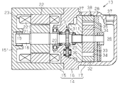
- the side sectional view showing a fluid machine.
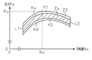
- Rotation speed vs. pressure graph showing a fluid machine.
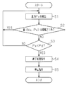
- the flowchart showing an abnormal pressure countermeasure control program The graph of the rotation speed versus pressure which shows 2nd Embodiment.
- the flowchart showing an abnormal pressure countermeasure control program The graph of the rotation speed versus pressure which shows 2nd Embodiment.
- a vehicle waste heat recovery device 10 as a Rankine cycle device includes an engine 11 and a Rankine cycle circuit 12 as a waste heat source.
- a Rankine cycle working fluid hereinafter referred to as a refrigerant
- a refrigerant heated by the waste heat from the engine 11 circulates in the Rankine cycle circuit 12.
- FIG. 1B shows a fluid machine 13 constituting the vehicle waste heat recovery apparatus 10.
- the fluid machine 13 includes a housing 14, and the housing 14 includes a rotating electrical machine housing 15, a pump housing 16 connected to the rotating electrical machine housing 15, and an expander housing 17 connected to the pump housing 16.
- a driving shaft 18 is rotatably supported by bearings 19 and 20 on the end wall 151 of the rotating electrical machine housing 15 and the pump housing 16, and a rotor 21 is fixed to the driving shaft 18.
- a stator 22 is fixed to the inner peripheral surface of the rotating electrical machine housing 15 so as to surround the rotor 21.
- the drive shaft 18, the stator 22 and the rotor 21 constitute a motor / generator 23 as a rotating electrical machine.
- the motor / generator 23 has a function as an electric motor that rotates the rotor 21 by energizing the coil 221 of the stator 22 and a function as a generator that generates electric power in the coil 221 of the stator 22 when the rotor 21 rotates. Have both.
- a battery 24 is electrically connected to the motor / generator 23 via an inverter 25.
- the electric power generated by the motor / generator 23 is stored in the battery 24 via the inverter 25.
- a control unit 26 is signal-connected to the inverter 25.
- a pair of side plates 27 and 28 are fixed in the expander housing 17 so as to face each other.
- a pump chamber 311 is defined between the pump housing 16 and the side plate 27.
- the drive shaft 18 passes through the pump housing 16 and the side plate 27.
- a drive gear 29 fixed to the drive shaft 18 and a driven gear 30 meshing with the drive gear 29 are disposed in the pump chamber 311.
- the pump chamber 311, the drive gear 29 and the driven gear 30 constitute a gear pump 31.
- a cylindrical cylinder block 32 is accommodated between the pair of side plates 27 and 28.
- a cylindrical rotor 33 is fixed to the drive shaft 18 in the cylinder block 32, and a plurality of vanes 34 are provided on the outer peripheral surface of the rotor 33 so as to be able to appear and retract.
- the drive shaft 18 rotates
- the rotor 33 rotates.
- the tip of the vane 34 slides on the inner peripheral surface of the cylinder block 32.
- the outer peripheral surface of the rotor 33, the inner peripheral surface of the cylinder block 32, and the adjacent vane 34 define a working chamber 35 between the pair of side plates 27 and 28.
- a discharge space 36 is defined between the expander housing 17 and the side plate 28, and a discharge port 37 is formed in the expander housing 17 so as to communicate with the discharge space 36.
- a suction port (not shown) communicating with the working chamber 35 is formed in the expander housing 17.
- the side plates 27 and 28, the cylinder block 32, the rotor 33, the vane 34, and the working chamber 35 constitute an expander 38 that outputs mechanical energy by expansion of the refrigerant.
- the Rankine cycle circuit 12 includes an expander 38 and a condenser 39 of the fluid machine 13, a gear pump 31 of the fluid machine 13, a first boiler 40, and a second boiler 41.
- the first boiler 40 includes a heat absorber 401 and a heat radiator 402.
- a heat absorber 401 of the first boiler 40 is connected to the discharge side of the pump chamber 311 [see FIG. 1B] in the gear pump 31 via the first flow path 42.
- the radiator 402 is provided on the cooling water circulation path 43 connected to the engine 11.
- a radiator 44 is provided on the cooling water circulation path 43. Cooling water (high temperature fluid) that has cooled the engine 11 of the vehicle circulates in the cooling water circulation path 43.
- a part of the heat of the cooling water circulating through the cooling water circulation path 43 is transmitted to the heat absorber 401 via the radiator 402 of the first boiler 40.
- a part of the heat of the cooling water circulating through the cooling water circulation path 43 is radiated by the radiator 44.
- the second boiler 41 includes a heat absorber 411 and a heat radiator 412.
- a heat absorber 411 of the second boiler 41 is connected to the discharge side of the heat absorber 401 of the first boiler 40 via a connection channel 47.
- the radiator 412 is provided on an exhaust passage 49 connected to the engine 11. The exhaust from the engine 11 is exhausted from the muffler 50 after radiating heat with the radiator 412.
- the refrigerant discharged from the gear pump 31 is heated by heat exchange between the heat absorbers 401 and 411 and the radiators 402 and 412 of the first boiler 40 and the second boiler 41.
- a suction port (not shown) in the expander 38 is connected to the discharge side of the heat absorber 411 of the second boiler 41 via a suction flow path 45.
- the high-temperature and high-pressure refrigerant heated by the first boiler 40 and the second boiler 41 is introduced into the expander 38 through the suction passage 45.
- the first flow path 42, the heat absorbers 401 and 411, the connection flow path 47, and the suction flow path 45 constitute a high-pressure flow path that is downstream of the gear pump 31 and upstream of the expander 38.
- a condenser 39 is connected to a discharge port 37 (see FIG. 1B) of the expander 38 via a discharge flow path 46.
- the low-pressure refrigerant expanded by the expander 38 is discharged to the condenser 39 via the discharge flow path 46.
- a pump chamber 311 (see FIG. 1B) of the gear pump 31 is connected to the discharge side of the condenser 39 via a second flow path 48.
- the bypass channel 51 is connected to the first channel 42.
- the bypass flow path 51 is connected to the discharge flow path 46 via a direction switching valve 52 that is excited and demagnetized.
- the direction switching valve 52 includes a normal state in which the suction channel 45 communicates with the condenser 39 via the expander 38 and the discharge channel 46 without passing through the bypass channel 51, and the discharge channel 46 is connected to the bypass channel 51. It is possible to switch from either one of the emergency states communicating with the first flow path 42 via the other 51 to the other.
- the direction switching valve 52 is in a normal state in a demagnetized state and in an emergency state in an excited state.
- the direction switching valve 52 is subjected to excitation / demagnetization control by the control unit 26.
- a pressure detector 53 is connected to the first flow path 42.
- the pressure detector 53 detects the pressure in the first flow path 42.
- the pressure detection information obtained by the pressure detector 53 as pressure detection means is sent to the control unit 26.
- the control unit 26 controls excitation and demagnetization of the direction switching valve 52 and the inverter 25 based on the pressure detection information obtained by the pressure detector 53.
- the operation of the vehicle waste heat recovery apparatus 10 is started by operating the motor / generator 23 as an electric motor.
- the control unit 26 sends a start command to the inverter 25, and the inverter 25 operates the motor / generator 23 as an electric motor based on the start command.
- the control unit 26 obtains temperature detection information from a temperature detector (not shown) that detects the temperature of the cooling water in the cooling water circulation path 43, and when the detected temperature becomes equal to or higher than a predetermined temperature, the control unit 26 displays the inverter 25. Command to start.
- the drive shaft 18 starts to rotate, and the drive gear 29 of the gear pump 31 and the rotor 33 of the expander 38 start to rotate integrally with the drive shaft 18.
- the rotation of the drive gear 29 of the gear pump 31 is transmitted to the driven gear 30, and the drive gear 29 and the driven gear 30 rotate in opposite directions while meshing with each other.
- the refrigerant in the second flow path 48 passes through the gear pump 31 and is sent to the first flow path 42.
- the refrigerant sent to the first flow path 42 passes through the heat absorber 401 of the first boiler 40, the connection flow path 47, and the heat absorber 411 of the second boiler 41, and is sent to the suction flow path 45.
- the refrigerant passing through the heat absorber 401 of the first boiler 40 and the heat absorber 411 of the second boiler 41 is heated by waste heat from the engine 11.
- the high-pressure refrigerant after heating is introduced from the suction port (not shown) into the working chamber 35 of the expander 38 and expands. Due to the expansion of the refrigerant, the expander 38 outputs mechanical energy (rotation imparting force), and the rotor 33 and the drive shaft 18 are rotated by the rotation imparting force.
- the expander 38 applies a rotational force to the drive shaft 18 of the motor / generator 23 using a refrigerant.
- the refrigerant whose pressure has decreased due to expansion is discharged into the discharge space 36 and then discharged into the discharge flow path 46 through the discharge port 37.
- the refrigerant discharged to the discharge flow path 46 passes through the condenser 39.
- the gear pump 31 is driven by the rotation of the drive shaft 18, the refrigerant discharged from the condenser 39 is introduced into the pump chamber 311 through the second flow path 48 and discharged from the pump chamber 311 to the first flow path 42.
- the refrigerant discharged to the first flow path 42 returns to the first boiler 40.
- the control unit 26 controls the motor / generator 23 to function as a generator after the start command, and the motor / generator 23 functions as a generator. Electric power obtained by the motor / generator 23 functioning as a generator is charged to the battery 24 via the inverter 25.
- the control unit 26 controls the inverter 25 so that the maximum generated power corresponding to the temperature of the cooling water is obtained. That is, the control unit 26 controls the rotation of the motor / generator 23 by instructing the inverter 25 to rotate the motor / generator 23 so that the maximum generated power can be obtained.
- FIG. 3 represents an abnormal pressure countermeasure control program for dealing with the abnormal pressure of the refrigerant.
- the abnormal pressure countermeasure control by the control unit 26 will be described based on the flowchart of FIG. 3 and the graph of FIG. 2.
- the direction switching valve 52 is in a demagnetized state, the suction flow path 45 communicates with the condenser 39 via the discharge flow path 46, and the first flow path 42 extends from the discharge flow path 46 via the bypass flow path 51. Communication with is blocked.
- the control unit 26 detects the pressure Px in the first flow path 42 at a predetermined sampling interval based on the pressure detection information obtained by the pressure detector 53 (step S1).
- the control unit 26 determines whether or not the set (Nx, Px) of the command rotational speed Nx commanded to the inverter 25 and the detected pressure Px is within the region Z1 shown in the graph of FIG. 2 (step S2).
- the horizontal axis represents the rotational speed
- the vertical axis represents the pressure
- the end line L1 represents the lower limit of the rotational speed Nx commanded to the inverter 25
- the end line L2 represents the upper limit of the rotational speed Nx commanded to the inverter 25.
- a region Zo indicated by diagonal lines surrounded by the curves K1, K2 and the end lines L1, L2 is a rotation speed versus pressure normal region set as a normal region.
- a region Z1 surrounded by the curves Kd and K1 and the end lines L1 and L2 is a rotation speed versus pressure allowable region set as a permitted region.
- the high pressure of the refrigerant depends on the refrigerant flow rate and the suction flow rate of the expander 38. It is determined within a certain range.
- the high pressure of the refrigerant is the pressure in the flow path downstream of the gear pump 31 and upstream of the expander 38, and the refrigerant flow rate is determined by the outside air temperature, the pump capacity of the gear pump 31, and the volume efficiency of the gear pump 31.
- the rotation speed versus pressure normal region Zo is set as the predetermined range.
- step S2 When the set (Nx, Px) is within the rotation speed versus pressure allowable region Z1 (YES in step S2), the control unit 26 proceeds to step S1.
- the control unit 26 determines the pressure Px in the set (Nx, Px) and a preset set (Nx, Px). A comparison is made with the pressure Pd at Pd) (step S3).
- the rotation speed Nx in the group (Nx, Pd) is the same as the rotation speed Nx in the group (Nx, Px).
- the group (Nd, Pd) in FIG. 2 is an example on the curve Kd.
- the pressure Pd is set as a lower limit pressure allowed at the rotational speed Nd.
- the lower side of the curve Kd shown in FIG. 2 is a low pressure region having a lower pressure than the allowable region Z1 of rotation speed versus pressure.
- a curve Kd is an index set to determine whether or not the refrigerant circulating in the Rankine cycle circuit 12 is insufficient.
- control unit 26 proceeds to step S1.
- the control unit 26 instructs the direction switching valve 52 to end processing (step S4).
- the end processing command for the direction switching valve 52 is an excitation command, and the direction switching valve 52 is switched from the demagnetized state to the excited state by this excitation command.
- the direction switching valve 52 is excited, the communication from the suction flow path 45 to the condenser 39 via the discharge flow path 46 is blocked, and the discharge flow path 46 is connected to the first flow path via the bypass flow path 51. 42 is communicated. Thereby, the refrigerant discharged from the expander 38 to the discharge flow path 46 goes to the first flow path 42 via the bypass flow path 51.
- the control unit 26 When a predetermined time has elapsed from the end processing command for the direction switching valve 52, the control unit 26 outputs a stop command to the inverter 25 (step S5).
- the stop command for the inverter 25 is a command for setting the rotation speed to zero. As a result, the rotation of the motor / generator 23 is stopped.
- the direction switching valve 52 is an opening / closing means that opens and closes the bypass channel 51.
- the control unit 26 and the inverter 25 constitute rotation control means for controlling the rotation of the drive shaft 18 and perform stop control.
- the stop control is control for stopping the rotation of the motor / generator 23 by the control unit 26 outputting a stop command for making the rotational speed of the drive shaft 18 zero to the inverter 25.
- the control unit 26 is a rotational speed command control unit that commands and controls the rotational speed of the motor / generator 23, and is a rotational speed grasping unit that grasps the rotational speed of the drive shaft 18.
- the control unit 26 is a determination unit that determines whether or not the set (Nx, Px) is within a preset rotation speed versus pressure allowable region.
- the refrigerant is insufficient if the set (Nx, Px) of the rotational speed Nx and the pressure Px in the first flow path 42 at this time is within a preset rotational speed versus pressure allowable region Z1. There is no. If the set (Nx, Px) of the rotational speed Nx and the pressure Px in the first flow path 42 at this time is in a region lower than the rotational speed versus pressure allowable region Z1, the refrigerant is insufficient. Whether the control unit 26 determines that the set (Nx, Px) of the pressure Px and the rotational speed Nx in the first flow path 42 is lower than the preset rotational speed versus pressure allowable region Z1. Determine whether or not. That is, since it is determined whether or not the pressure Px is too low according to the rotational speed Nx (the rotational speed of the gear pump 31 and the expander 38), it is possible to accurately grasp whether or not the refrigerant is insufficient. .
- the rotational force applied to the drive shaft 18 by the expander 38 is gradually reduced. go.
- the stop command for setting the rotational speed to zero is issued after a predetermined time has elapsed from the end processing command. During this predetermined time, the rotation given to the drive shaft 18 by the expander 38 so that the rotation of the drive shaft 18 does not increase. It is set as the time required for the force to be sufficiently reduced. Therefore, a sudden increase in the rotational speed of the drive shaft 18 can be avoided.
- the information on the rotational speed commanded by the control unit 26 is simple as information for grasping the rotational speed of the drive shaft 18 (the rotational speed of the gear pump 31 and the expander 38).
- the second boiler 41 has a higher temperature than the first boiler 40, and the first boiler 42 is upstream of the first boiler 40 and the second boiler 41 among the high-pressure channels 42, 47, 45.
- FIGS. 4 and 5 will be described.
- the same reference numerals are used for the same components as those in the first embodiment, and detailed description thereof is omitted.
- the same reference numerals are used for the same control steps, and detailed description thereof will be omitted.
- a region Z2 surrounded by the curves Kd and Ku and the end lines L1 and L2 in the graph of FIG. 4 is a rotational speed versus pressure permissible region set as a permissible region.
- the upper side of the curve Ku is a high pressure region having a higher pressure than the allowable region Z2 of the rotational speed versus pressure.
- a set (Nu, Pu) of the rotational speed Nu and the pressure Pu is an example on the curve Ku.
- the control unit 26 determines whether or not the set (Nx, Px) of the rotational speed Nx commanded to the inverter 25 and the detected pressure Px is within a region Z2 shown in the graph of FIG. 4. (Step S21). When the set (Nx, Px) is within the allowable range Z2 of rotation speed versus pressure (YES in step S21), the control unit 26 proceeds to step S1. When the set (Nx, Px) is not within the allowable range Z2 of rotation speed versus pressure (NO in step S21), the control unit 26 proceeds to step S4.
- the pressure in the first flow path 42 may become abnormally high due to foreign matter clogging.
- the control unit 26 determines whether or not the set (Nx, Px) of the pressure Px and the rotational speed Nx in the first flow path 42 thus grasped is in a higher pressure region than the preset rotational speed versus pressure allowable region Z2. Judgment is made. That is, since it is determined whether or not the pressure Px is too high according to the rotational speed Nx (the rotational speed of the gear pump 31 and the expander 38), it is possible to accurately grasp whether or not the refrigerant is in an abnormally high pressure state. Can do.
- a region surrounded by the curves K2 and Ku and the end lines L1 and L2 is an allowable region for the rotational speed versus pressure, and the set (Nx, Px) is not within the allowable region for the rotational speed versus pressure.
- the magnitude comparison between the pressure Px in the group (Nx, Px) and the preset pressure Pu may be performed.
- the area Zo may be set as an allowable area for the rotational speed versus pressure.
- the pressure in the connection channel 47 may be detected. You may make it detect the pressure in the heat sinks 401 and 411, the connection flow path 47, or the suction flow path 45. FIG.
- an on-off valve may be provided in the middle of the bypass channel 51.
- the bypass channel 51 and the direction switching valve 52 may be eliminated.
- a rotation speed detection means for detecting the rotation speed of the drive shaft 18 may be provided, and this rotation speed detection means may be used as the rotation speed grasping means.
- the rotating electrical machine may function only as a generator.
- the present invention may be applied to a complex fluid machine in which a clutch is provided between the rotation shaft of the compressor and the drive shaft 18 so that the rotation of the drive shaft 18 can be transmitted to the rotation shaft of the compressor.
- an axial fan may be attached to the drive shaft 18 so that the refrigerant flows in the axial direction of the drive shaft 18 to rotate the axial fan and the drive shaft 18 integrally.
- the expander may be configured by a movable scroll and a fixed scroll, similarly to a scroll compressor provided with a movable scroll and a fixed scroll.
- the present invention may be applied to Rankine cycle devices other than those for vehicles.
Landscapes
- Engineering & Computer Science (AREA)
- Mechanical Engineering (AREA)
- General Engineering & Computer Science (AREA)
- Chemical & Material Sciences (AREA)
- Combustion & Propulsion (AREA)
- Applications Or Details Of Rotary Compressors (AREA)
- Engine Equipment That Uses Special Cycles (AREA)
Abstract
第1流路(42)に接続された圧力検出器(53)は、第1流路(42)内の圧力を検出する。制御部(26)は、圧力検出器(53)によって得られた圧力検出情報に基づいて、インバータ(25)を制御する。制御部(26)は、回転数(Nx)と検出圧力(Px)との組(Nx,Px)における圧力(Px)と、予め設定された回転数(Nx)と圧力(Pd)との組(Nx,Pd)における圧力(Pd)との大小比較を行なう。制御部(26)は、前記組における圧力(Px)が回転数対圧力の許容領域よりも低圧領域または高圧領域(例えばPd>Px)にある場合、制御部(26)は、インバータ(25)に対して停止指令を出力する。このため、ランキンサイクル用作動流体の圧力が異常か否かを適正に把握して廃熱回収を停止できる。
Description
本発明は、少なくとも発電機として機能する回転電機と、前記回転電機の回転数を制御する回転数制御手段と、ランキンサイクル用作動流体を利用して前記回転電機の駆動軸に回転力を付与する膨張機と、ランキンサイクル用作動流体を吸入して吐出するポンプとを備えたランキンサイクル装置に関する。
この種のランキンサイクル装置では、ランキンサイクル用作動流体である冷媒がサイクルから洩れた場合、ポンプ上流域でサイクル内の作動流体が、ガスが混じった状態(キャビテーション)あるいは全てガスの状態になることがある。このような状態になると、作動流体の流量が低下してしまう。作動流体の流量が低下した状態でランキンサイクルを稼動し続けると、回生動力が低下したり、作動流体と共に流動する潤滑油が不足して潤滑必要部位の潤滑が悪くなる。あるいは、エンジン等の発熱体を冷却する冷却水から熱を奪って作動流体に移す熱交換器すなわちボイラからの熱によって作動流体が過熱する。作動流体が高温によって劣化するものである場合、作動流体が劣化してしまうおそれもある。
特許文献1に開示されているランキンサイクル装置では、ランキンサイクル用作動流体を熱交換器すなわちボイラへ送り出すポンプの上流側の圧力と下流側の圧力との差が所定圧力以下になった場合に、廃熱回収モードが停止される。廃熱回収モードを停止すれば、ランキンサイクル用作動流体の流量の低下に起因する上述の問題を回避することができる。
しかし、ポンプの上流側の圧力と下流側の圧力との差が所定圧力以下になったとしても、ポンプの下流側の圧力が低いとは限らない。つまり、前記差が所定圧力以下になったとしても、サイクル内の作動流体がガスが混じった状態(キャビテーション)あるいは全てガス状になった状態とは限らない。そのため、ポンプの上流側の圧力と下流側の圧力との差の情報では、作動流体すなわち冷媒が不足しているか否かを精度良く把握することができず、廃熱回収効率が低下する。
ランキンサイクル用作動流体すなわち冷媒が不足か否かを検出するには、ポンプの下流側の圧力を検出することが必要である。しかし、作動流体すなわち冷媒が不足する状況を反映するポンプの下流側の圧力の上限は、回転数によって変動する。従って、ポンプの下流側の圧力を検出するのみでは、作動流体すなわち冷媒が不足か否かを精度良く把握することはできない。
本発明の目的は、ランキンサイクル用作動流体すなわち冷媒の圧力が異常か否かを適正に把握して廃熱回収を停止できるようにすることにある。
本発明は、少なくとも発電機として機能する回転電機と、ランキンサイクル用作動流体を利用して前記回転電機の駆動軸に回転力を付与する膨張機と、ランキンサイクル用作動流体を吸入して吐出するポンプと、前記駆動軸の回転を制御する回転制御手段とを備え、前記膨張機と前記ポンプとが一体的に回転するランキンサイクル装置を対象とし、請求項1の発明では、前記ポンプの下流であって前記膨張機の上流である高圧流路内の圧力を検出する圧力検出手段と、前記駆動軸の回転数を把握する回転数把握手段と、前記回転数把握手段によって把握された回転数と、前記圧力検出手段によって検出された圧力との組が予め設定された回転数対圧力の許容領域にあるか否かを判定する判定手段とを備え、前記回転制御手段は、前記組における圧力が前記回転数対圧力の許容領域よりも低圧領域にある場合には、前記回転電機の回転数を零にする停止制御を行なう。
把握された高圧流路内の圧力と回転数との組が予め設定された回転数対圧力の許容領域よりも低圧領域にあるか否かの判定が行なわれるため、ランキンサイクル用作動流体が不足しているか否かを精度良く把握することができる。
好適な例では、前記回転制御手段は、前記組における圧力が前記回転数対圧力の許容領域よりも高圧領域にある場合には、前記停止制御を行なう。
高圧流路内の圧力は、異物詰まりによって異常高圧化することもある。把握された高圧流路内の圧力と回転数との組が予め設定された回転数対圧力の許容領域よりも高圧領域にあるか否かを判定するため、ランキンサイクル用作動流体の異常高圧を精度良く把握することができる。
高圧流路内の圧力は、異物詰まりによって異常高圧化することもある。把握された高圧流路内の圧力と回転数との組が予め設定された回転数対圧力の許容領域よりも高圧領域にあるか否かを判定するため、ランキンサイクル用作動流体の異常高圧を精度良く把握することができる。
請求項3の発明では、少なくとも発電機として機能する回転電機と、ランキンサイクル用作動流体を利用して前記回転電機の駆動軸に回転力を付与する膨張機と、ランキンサイクル用作動流体を吸入して吐出するポンプと、前記駆動軸の回転を制御する回転制御手段とを備え、前記膨張機と前記ポンプとが一体的に回転するランキンサイクル装置において、前記ポンプの下流であって前記膨張機の上流である高圧流路内の圧力を検出する圧力検出手段と、前記駆動軸の回転数を把握する回転数把握手段と、前記圧力検出手段によって検出された圧力と、前記回転数把握手段によって把握された回転数との組が予め設定された回転数対圧力の許容領域にあるか否かを判定する判定手段とを備え、前記回転制御手段は、前記組における圧力が前記回転数対圧力の許容領域よりも高圧領域にある場合には、前記駆動軸の回転数を零にする停止制御を行なう。
好適な例では、前記膨張機の下流側と前記高圧流路とを繋ぐバイパス流路が設けられており、前記バイパス流路には前記バイパス流路を開閉する開閉手段が設けられており、前記停止制御は、バイパス流路を開くように前記開閉手段を制御し、且つその後に前記駆動軸の回転数を零にする制御を含む。
回転数指令制御手段がいきなり回転数を零にする指令を行なうと、回転数が急上昇する可能性がある。回転数を零にする指令を行なう前にバイパス流路を開けば、回転数の急上昇を回避することができる。
好適な例では、前記回転制御手段は、前記回転電機の回転数を指令して制御する回転数指令制御手段を含む。
回転数制御手段によって指令される回転数の情報は、回転数を把握する情報として簡便である。
回転数制御手段によって指令される回転数の情報は、回転数を把握する情報として簡便である。
以下、本発明の第1の実施形態の車両用廃熱回収装置を図1~図3に基づいて説明する。
図1Aに示すように、ランキンサイクル装置としての車両用廃熱回収装置10は、廃熱源としてのエンジン11とランキンサイクル回路12とを備えている。車両用廃熱回収装置10では、エンジン11からの廃熱によって加熱されるランキンサイクル用作動流体(以下においては冷媒と記す)がランキンサイクル回路12を循環する。
図1Aに示すように、ランキンサイクル装置としての車両用廃熱回収装置10は、廃熱源としてのエンジン11とランキンサイクル回路12とを備えている。車両用廃熱回収装置10では、エンジン11からの廃熱によって加熱されるランキンサイクル用作動流体(以下においては冷媒と記す)がランキンサイクル回路12を循環する。
図1Bは、車両用廃熱回収装置10を構成する流体機械13を示す。流体機械13はハウジング14を備え、ハウジング14は回転電機ハウジング15と、回転電機ハウジング15に連結されたポンプハウジング16と、ポンプハウジング16に連結された膨張機ハウジング17から構成されている。
回転電機ハウジング15の端壁151とポンプハウジング16とには駆動軸18が軸受19,20を介して回転可能に支持されており、駆動軸18にはロータ21が固定されている。回転電機ハウジング15の内周面にはステータ22がロータ21を取り囲むように固定されている。駆動軸18、ステータ22及びロータ21は、回転電機としてのモータ・ジェネレータ23を構成する。
モータ・ジェネレータ23は、ステータ22のコイル221への通電によってロータ21を回転させる電動機としての機能と、ロータ21が回転することによってステータ22のコイル221に電力を生じさせる発電機としての機能とを併せ持つ。
図1Aに示すように、モータ・ジェネレータ23にはバッテリ24がインバータ25を介して電気的に接続されている。モータ・ジェネレータ23で生じた電力は、インバータ25を介してバッテリ24に蓄電される。インバータ25には制御部26が信号接続されている。
図1Bに戻ると、膨張機ハウジング17内には一対のサイドプレート27,28が互いに対向するように固定されている。ポンプハウジング16とサイドプレート27との間にはポンプ室311が区画されている。駆動軸18は、ポンプハウジング16及びサイドプレート27を貫通している。ポンプ室311内には駆動軸18に止着された駆動ギヤ29と、駆動ギヤ29に噛合する従動ギヤ30とが配設されている。ポンプ室311、駆動ギヤ29及び従動ギヤ30は、ギヤポンプ31を構成する。
一対のサイドプレート27,28間には筒状をなすシリンダブロック32が収容されている。シリンダブロック32内において駆動軸18には円筒状をなすロータ33が止着されており、ロータ33の外周面には複数のベーン34が出没可能に設けられている。駆動軸18が回転するとロータ33が回転する。ロータ33の回転に伴い、ベーン34の先端がシリンダブロック32の内周面を摺接する。ロータ33の外周面、シリンダブロック32の内周面及び隣り合うベーン34は、一対のサイドプレート27,28間に作動室35を区画する。
膨張機ハウジング17とサイドプレート28との間には吐出空間36が区画されており、膨張機ハウジング17には吐出ポート37が吐出空間36に連通するように形成されている。膨張機ハウジング17には作動室35に連通する吸入ポート(図示せず)が形成されている。
サイドプレート27,28、シリンダブロック32、ロータ33、ベーン34及び作動室35は、冷媒の膨張によって機械的エネルギーを出力する膨張機38を構成する。
次に、車両用廃熱回収装置10におけるランキンサイクル回路12について説明する。
次に、車両用廃熱回収装置10におけるランキンサイクル回路12について説明する。
ランキンサイクル回路12は、流体機械13の膨張機38、凝縮器39、流体機械13のギヤポンプ31、第1ボイラ40、及び第2ボイラ41によって構成されている。
第1ボイラ40は、吸熱器401と放熱器402とを備える。ギヤポンプ31におけるポンプ室311〔図1B参照〕の吐出側には第1ボイラ40の吸熱器401が第1流路42を介して接続されている。放熱器402は、エンジン11に接続された冷却水循環経路43上に設けられている。冷却水循環経路43上にはラジエータ44が設けられている。車両のエンジン11を冷却した冷却水(高温流体)は、冷却水循環経路43を循環する。冷却水循環経路43を循環する冷却水の熱の一部は、第1ボイラ40の放熱器402を介して吸熱器401へ伝達される。又、冷却水循環経路43を循環する冷却水の熱の一部は、ラジエータ44で放熱される。
第1ボイラ40は、吸熱器401と放熱器402とを備える。ギヤポンプ31におけるポンプ室311〔図1B参照〕の吐出側には第1ボイラ40の吸熱器401が第1流路42を介して接続されている。放熱器402は、エンジン11に接続された冷却水循環経路43上に設けられている。冷却水循環経路43上にはラジエータ44が設けられている。車両のエンジン11を冷却した冷却水(高温流体)は、冷却水循環経路43を循環する。冷却水循環経路43を循環する冷却水の熱の一部は、第1ボイラ40の放熱器402を介して吸熱器401へ伝達される。又、冷却水循環経路43を循環する冷却水の熱の一部は、ラジエータ44で放熱される。
第2ボイラ41は、吸熱器411と放熱器412とを備える。第1ボイラ40の吸熱器401の吐出側には第2ボイラ41の吸熱器411が接続流路47を介して接続されている。放熱器412は、エンジン11に接続された排気通路49上に設けられている。エンジン11からの排気は、放熱器412で放熱した後にマフラ50から排気される。
ギヤポンプ31から吐出された冷媒は、第1ボイラ40及び第2ボイラ41の吸熱器401,411と放熱器402,412との間での熱交換により加熱される。
第2ボイラ41の吸熱器411の吐出側には膨張機38における吸入ポート〔図示略〕が吸入流路45を介して接続されている。第1ボイラ40及び第2ボイラ41で加熱された高温高圧の冷媒は、吸入流路45を介して膨張機38に導入されるようになっている。第1流路42、吸熱器401,411、接続流路47及び吸入流路45は、ギヤポンプ31の下流であって膨張機38の上流である高圧流路を構成する。
第2ボイラ41の吸熱器411の吐出側には膨張機38における吸入ポート〔図示略〕が吸入流路45を介して接続されている。第1ボイラ40及び第2ボイラ41で加熱された高温高圧の冷媒は、吸入流路45を介して膨張機38に導入されるようになっている。第1流路42、吸熱器401,411、接続流路47及び吸入流路45は、ギヤポンプ31の下流であって膨張機38の上流である高圧流路を構成する。
膨張機38の吐出ポート37〔図1B参照〕には凝縮器39が吐出流路46を介して接続されている。膨張機38で膨張した低圧の冷媒は、吐出流路46を介して凝縮器39へ吐出されるようになっている。凝縮器39の吐出側にはギヤポンプ31のポンプ室311〔図1B参照〕が第2流路48を介して接続されている。
第1流路42にはバイパス流路51が接続されている。バイパス流路51は、励消磁される方向切り換え弁52を介して吐出流路46に接続されている。方向切り換え弁52は、バイパス流路51を介さずに、吸入流路45から、膨張機38、吐出流路46を介して凝縮器39に連通する通常状態と、吐出流路46がバイパス流路51を介して第1流路42と連通する緊急状態とのいずれか一方から他方へ切り換え可能である。方向切り換え弁52は、消磁状態では通常状態にあると共に、励磁状態では緊急状態にある。方向切り換え弁52は、制御部26の励消磁制御を受ける。
第1流路42には圧力検出器53が接続されている。圧力検出器53は、第1流路42内の圧力を検出する。圧力検出手段としての圧力検出器53によって得られた圧力検出情報は、制御部26へ送られる。制御部26は、圧力検出器53によって得られた圧力検出情報に基づいて、方向切り換え弁52の励消磁及びインバータ25を制御する。
次に、車両用廃熱回収装置10の作用について説明する。
車両用廃熱回収装置10の作動は、モータ・ジェネレータ23を電動機として作動させることによって開始される。制御部26は、インバータ25に対して起動指令を送り、インバータ25は、起動指令に基づいてモータ・ジェネレータ23を電動機として作動させる。制御部26は、冷却水循環経路43内の冷却水の温度を検出する温度検出器(図示略)から温度検出情報を得ており、検出温度が所定温度以上になると、制御部26は、インバータ25に対して起動を指令する。モータ・ジェネレータ23が電動機として作動されると、駆動軸18が回転開始し、ギヤポンプ31の駆動ギヤ29及び膨張機38のロータ33が駆動軸18と一体的に回転開始する。ギヤポンプ31の駆動ギヤ29の回転は、従動ギヤ30に伝達され、駆動ギヤ29及び従動ギヤ30が噛合しながら互いに逆方向に回転する。これにより第2流路48の冷媒がギヤポンプ31を通過して第1流路42へ送られる。
車両用廃熱回収装置10の作動は、モータ・ジェネレータ23を電動機として作動させることによって開始される。制御部26は、インバータ25に対して起動指令を送り、インバータ25は、起動指令に基づいてモータ・ジェネレータ23を電動機として作動させる。制御部26は、冷却水循環経路43内の冷却水の温度を検出する温度検出器(図示略)から温度検出情報を得ており、検出温度が所定温度以上になると、制御部26は、インバータ25に対して起動を指令する。モータ・ジェネレータ23が電動機として作動されると、駆動軸18が回転開始し、ギヤポンプ31の駆動ギヤ29及び膨張機38のロータ33が駆動軸18と一体的に回転開始する。ギヤポンプ31の駆動ギヤ29の回転は、従動ギヤ30に伝達され、駆動ギヤ29及び従動ギヤ30が噛合しながら互いに逆方向に回転する。これにより第2流路48の冷媒がギヤポンプ31を通過して第1流路42へ送られる。
第1流路42へ送られた冷媒は、第1ボイラ40の吸熱器401、接続流路47、及び第2ボイラ41の吸熱器411を通過して吸入流路45へ送られる。第1ボイラ40の吸熱器401及び第2ボイラ41の吸熱器411を通過する冷媒は、エンジン11からの廃熱によって加熱される。加熱後の高圧の冷媒は、吸入ポート(図示せず)から膨張機38の作動室35に導入されて膨張する。この冷媒の膨張により膨張機38が機械的エネルギー(回転付与力)を出力し、この回転付与力によってロータ33及び駆動軸18が回転する。膨張機38は、冷媒を利用してモータ・ジェネレータ23の駆動軸18に回転力を付与する。
膨張して圧力が低下した冷媒は、吐出空間36に吐出された後、吐出ポート37を介して吐出流路46へ吐出される。吐出流路46へ吐出された冷媒は、凝縮器39を通過する。駆動軸18の回転によるギヤポンプ31の駆動に伴い、凝縮器39から吐出された冷媒は、第2流路48を介してポンプ室311に導入され、ポンプ室311から第1流路42へ吐出される。第1流路42へ吐出された冷媒は、第1ボイラ40へと還流する。
モータ・ジェネレータ23を電動機として作動開始した後では、膨張機38によって出力される機械的エネルギー(回転付与力)が駆動軸18を回転させる。制御部26は、起動指令後にはモータ・ジェネレータ23を発電機として機能するように制御し、モータ・ジェネレータ23は、発電機として機能する。発電機として機能するモータ・ジェネレータ23によって得られた電力は、インバータ25を介してバッテリ24に充電される。制御部26は、冷却水の温度に応じた最大発電電力が得られるように、インバータ25を制御する。つまり、制御部26は、最大発電電力が得られるようにモータ・ジェネレータ23の回転数をインバータ25に指令してモータ・ジェネレータ23の回転を制御する。
図3のフローチャートは、冷媒の異常圧力に対処するための異常圧力対処制御プログラムを表す。以下、制御部26による異常圧力対処制御を図3のフローチャート及び図2のグラフに基づいて説明する。
方向切り換え弁52は、消磁状態にあり、吸入流路45が吐出流路46を介して凝縮器39に連通していると共に、吐出流路46からバイパス流路51を介した第1流路42への連通が遮断されている。制御部26は、圧力検出器53によって得られる圧力検出情報に基づいて所定のサンプリング間隔で第1流路42内の圧力Pxを検出する(ステップS1)。制御部26は、インバータ25に指令する指令回転数Nxと検出した圧力Pxとの組(Nx,Px)が図2のグラフに示す領域Z1内にあるか否かを判断する(ステップS2)。
図2のグラフにおいて、横軸は、回転数を表し、縦軸は、圧力を表す。端線L1は、インバータ25に指令される回転数Nxの下限を表し、端線L2は、インバータ25に指令される回転数Nxの上限を表す。曲線K1,K2と端線L1,L2とで囲まれる斜線で示される領域Zoは、正常な領域として設定された回転数対圧力正常領域である。曲線Kd,K1と端線L1,L2とで囲まれる領域Z1は、許容される領域として設定された回転数対圧力の許容領域である。
ギヤポンプ31と膨張機38とが一体的に回転する構成(ギヤポンプ31の回転数と膨張機38の回転数とが同一)では、冷媒の高圧は、冷媒流量と、膨張機38の吸入流量とによりほぼ一定範囲に決まる。冷媒の高圧は、ギヤポンプ31より下流かつ膨張機38より上流の流路内の圧力であり、冷媒流量は、外気温、ギヤポンプ31のポンプ容量、ギヤポンプ31の体積効率により決まる。回転数対圧力正常領域Zoは、前記の一定範囲として設定されている。ギヤポンプ31より下流かつ膨張機38より上流の流路内の圧力が回転数対圧力正常領域Zoを下回れば、冷媒流量が減少してキャビテーションが発生する可能性が高い。領域Zoを外れていても、領域Z1内では異常との判断をせず、排熱回収の継続を許容する。
組(Nx,Px)が回転数対圧力の許容領域Z1内にある場合(ステップS2においてYES)、制御部26は、ステップS1へ移行する。組(Nx,Px)が回転数対圧力の許容領域Z1内にない場合(ステップS2においてNO)、制御部26は、組(Nx,Px)における圧力Pxと、予め設定された組(Nx,Pd)における圧力Pdとの大小比較を行なう(ステップS3)。組(Nx,Pd)における回転数Nxは、組(Nx,Px)における回転数Nxと同じ回転数である。図2における組(Nd,Pd)は、曲線Kd上の一例である。圧力Pdは、回転数Ndにおいて許容される下限圧力として設定される。
図2に示す曲線Kdよりも下側は、回転数対圧力の許容領域Z1よりも低圧の低圧領域である。第1流路42内の冷媒圧力が曲線Kdよりも下側の低圧領域にある場合には、冷媒不足によってキャビテーションが発生する場合である。曲線Kdは、ランキンサイクル回路12を循環する冷媒が不足しているか否かを判断するために設定された指標である。
圧力Pxが圧力Pd以上である場合(ステップS3においてNO)、制御部26は、ステップS1へ移行する。
圧力Pxが圧力Pdに満たない場合(ステップS3においてYES)、制御部26は、方向切り換え弁52に終了処理を指令する(ステップS4)。
圧力Pxが圧力Pdに満たない場合(ステップS3においてYES)、制御部26は、方向切り換え弁52に終了処理を指令する(ステップS4)。
方向切り換え弁52に対する終了処理指令は、励磁指令であり、この励磁指令により方向切り換え弁52が消磁状態から励磁状態へ切り換えられる。方向切り換え弁52が励磁されると、吸入流路45から吐出流路46を介した凝縮器39への連通が遮断されると共に、吐出流路46がバイパス流路51を介して第1流路42と連通される。これにより、膨張機38から吐出流路46へ吐出された冷媒は、バイパス流路51を経由して第1流路42へ向かう。
方向切り換え弁52に対する終了処理指令から所定時間が経過すると、制御部26は、インバータ25に対して停止指令を出力する(ステップS5)。インバータ25に対する停止指令は、回転数を零とする指令である。これによりモータ・ジェネレータ23の回転が停止する。
方向切り換え弁52は、バイパス流路51を開閉する開閉手段である。制御部26及びインバータ25は、駆動軸18の回転を制御する回転制御手段を構成し、停止制御を行なう。停止制御とは、制御部26がインバータ25に対して駆動軸18の回転数を零にする停止指令を出力して、モータ・ジェネレータ23の回転を停止する制御である。制御部26は、モータ・ジェネレータ23の回転数を指令して制御する回転数指令制御手段であり、且つ駆動軸18の回転数を把握する回転数把握手段である。又、制御部26は、組(Nx,Px)が予め設定された回転数対圧力の許容領域にあるか否かを判定する判定手段である。
第1の実施形態では以下の効果が得られる。
(1)回転数Nxとこのときの第1流路42内の圧力Pxとの組(Nx,Px)が予め設定された回転数対圧力の許容領域Z1にあれば冷媒が不足していることはない。回転数Nxとこのときの第1流路42内の圧力Pxとの組(Nx,Px)が回転数対圧力の許容領域Z1よりも低圧の領域にあれば冷媒が不足している。制御部26は、把握された第1流路42内の圧力Pxと回転数Nxとの組(Nx,Px)が予め設定された回転数対圧力の許容領域Z1よりも低圧の領域にあるか否かの判定を行なう。つまり、回転数Nx(ギヤポンプ31及び膨張機38の回転数)に応じて圧力Pxが低すぎるか否かの判定が行なわれるため、冷媒が不足しているか否かを精度良く把握することができる。
(1)回転数Nxとこのときの第1流路42内の圧力Pxとの組(Nx,Px)が予め設定された回転数対圧力の許容領域Z1にあれば冷媒が不足していることはない。回転数Nxとこのときの第1流路42内の圧力Pxとの組(Nx,Px)が回転数対圧力の許容領域Z1よりも低圧の領域にあれば冷媒が不足している。制御部26は、把握された第1流路42内の圧力Pxと回転数Nxとの組(Nx,Px)が予め設定された回転数対圧力の許容領域Z1よりも低圧の領域にあるか否かの判定を行なう。つまり、回転数Nx(ギヤポンプ31及び膨張機38の回転数)に応じて圧力Pxが低すぎるか否かの判定が行なわれるため、冷媒が不足しているか否かを精度良く把握することができる。
(2)制御部26がいきなり回転数を零にする指令を行なうと、モータ・ジェネレータ23における発電が停止され、膨張機38によって駆動軸18に付与される回転力に対して回転抵抗が急激になくなる。そのため、駆動軸18の回転が急上昇する。そうすると、異音が発生したり、軸受19,20の信頼性が損なわれる。
本実施形態では、バイパス流路51を開き、その後に駆動軸18の回転数を零にするという制御が行なわれるため、膨張機38によって駆動軸18に付与される回転力が徐々に低減してゆく。回転数を零にする停止指令は、終了処理指令から所定時間経過後に行なわれるが、この所定時間は、駆動軸18の回転が上昇しないように、膨張機38によって駆動軸18に付与される回転力が十分に低減するのに要する時間として設定される。従って、駆動軸18の回転数の急上昇を回避することができる。
(3)制御部26によって指令される回転数の情報は、駆動軸18の回転数(ギヤポンプ31及び膨張機38の回転数)を把握する情報として簡便である。
(4)第2ボイラ41は第1ボイラ40よりも高温であり、高圧域の流路42,47,45の中でも、第1ボイラ40及び第2ボイラ41の上流である第1流路42に、圧力検出器53を接続することで、第1ボイラ40及び第2ボイラ41の熱の影響を受けにくくなる。そのため、圧力検出器53に対して特別の防熱対策を施す必要がなく、圧力検出器53のコスト増を回避することができる。
(4)第2ボイラ41は第1ボイラ40よりも高温であり、高圧域の流路42,47,45の中でも、第1ボイラ40及び第2ボイラ41の上流である第1流路42に、圧力検出器53を接続することで、第1ボイラ40及び第2ボイラ41の熱の影響を受けにくくなる。そのため、圧力検出器53に対して特別の防熱対策を施す必要がなく、圧力検出器53のコスト増を回避することができる。
次に、図4及び図5の第2の実施形態を説明する。第1の実施形態と同じ構成部には同じ符合を用い、その詳細説明は省略する。又、図5のフローチャートにおいて同じ制御ステップには同じ符合を用い、その詳細説明は省略する。
図4のグラフにおける曲線Kd,Kuと端線L1,L2とで囲まれる領域Z2は、許容される領域として設定された回転数対圧力の許容領域である。曲線Kuよりも上側は、回転数対圧力の許容領域Z2よりも高圧の高圧領域である。回転数Nu及び圧力Puの組(Nu,Pu)は、曲線Ku上の一例である。第1流路42内の冷媒圧力が曲線Kuよりも上側の高圧領域にある場合には、異物詰まりによって異常高圧が発生する場合である。曲線Kuは、第1流路42内の冷媒が異常高圧になっているか否かを判断するために設定された指標である。領域Zoを外れていても、領域Z2内では異常との判断をせず、排熱回収の継続を許容する。
図5に示すように、制御部26は、インバータ25に指令する回転数Nxと検出した圧力Pxとの組(Nx,Px)が図4のグラフに示す領域Z2内にあるか否かを判断する(ステップS21)。組(Nx,Px)が回転数対圧力の許容領域Z2内にある場合(ステップS21においてYES)、制御部26は、ステップS1へ移行する。組(Nx,Px)が回転数対圧力の許容領域Z2内にない場合(ステップS21においてNO)、制御部26は、ステップS4へ移行する。
第1流路42内の圧力は、異物詰まりによって異常高圧化することもある。制御部26は、把握された第1流路42内の圧力Pxと回転数Nxとの組(Nx,Px)が予め設定された回転数対圧力の許容領域Z2よりも高圧領域にあるか否かの判定を行なう。つまり、回転数Nx(ギヤポンプ31及び膨張機38の回転数)に応じて圧力Pxが高すぎるか否かの判定が行なわれるため、冷媒が異常高圧状態にあるか否かを精度良く把握することができる。
本発明では以下のような実施形態も可能である。
第2の実施形態において、曲線K2,Kuと端線L1,L2とで囲まれる領域を回転数対圧力の許容領域とし、組(Nx,Px)がこの回転数対圧力の許容領域内にない場合には、組(Nx,Px)における圧力Pxと、予め設定された圧力Puとの大小比較のみを行なうようにしてもよい。
第2の実施形態において、曲線K2,Kuと端線L1,L2とで囲まれる領域を回転数対圧力の許容領域とし、組(Nx,Px)がこの回転数対圧力の許容領域内にない場合には、組(Nx,Px)における圧力Pxと、予め設定された圧力Puとの大小比較のみを行なうようにしてもよい。
領域Zoを回転数対圧力の許容領域としてもよい。
接続流路47における圧力を検出するようにしてもよい。
吸熱器401,411内、接続流路47あるいは吸入流路45における圧力を検出するようにしてもよい。
接続流路47における圧力を検出するようにしてもよい。
吸熱器401,411内、接続流路47あるいは吸入流路45における圧力を検出するようにしてもよい。
方向切り換え弁52の代わりに、バイパス流路51の途中に開閉弁を設けてもよい。
バイパス流路51及び方向切り換え弁52を無くしてもよい。
駆動軸18の回転数を検出する回転数検出手段を設け、この回転数検出手段を回転数把握手段としてもよい。
バイパス流路51及び方向切り換え弁52を無くしてもよい。
駆動軸18の回転数を検出する回転数検出手段を設け、この回転数検出手段を回転数把握手段としてもよい。
回転電機は、発電機としてのみ機能するものであってもよい。
圧縮機の回転軸と駆動軸18との間にクラッチを設け、駆動軸18の回転を圧縮機の回転軸に伝達できるようにした複合流体機械に本発明を適用してもよい。
圧縮機の回転軸と駆動軸18との間にクラッチを設け、駆動軸18の回転を圧縮機の回転軸に伝達できるようにした複合流体機械に本発明を適用してもよい。
膨張機として、ベーン式以外の他の形式の膨張機を用いてもよい。例えば、駆動軸18に軸流ファンを取り付け、駆動軸18の軸方向に冷媒を流して軸流ファン及び駆動軸18を一体的に回転させるようにしてもよい。
膨張機は、可動スクロールと固定スクロールとを備えたスクロール型圧縮機と同様に可動スクロールと固定スクロールとによって構成されてもよい。
車両用以外のランキンサイクル装置に本発明を適用してもよい。
車両用以外のランキンサイクル装置に本発明を適用してもよい。
Claims (5)
- 少なくとも発電機として機能する回転電機と、ランキンサイクル用作動流体を利用して前記回転電機の駆動軸に回転力を付与する膨張機と、該作動流体を吸入して吐出するポンプと、前記駆動軸の回転を制御する回転制御手段とを備え、前記膨張機と前記ポンプとが一体的に回転するランキンサイクル装置において、
前記ポンプの下流であって前記膨張機の上流である高圧流路内の圧力を検出する圧力検出手段と、
前記駆動軸の回転数を把握する回転数把握手段と、
前記回転数把握手段によって把握された回転数と、前記圧力検出手段によって検出された圧力との組が予め設定された回転数対圧力の許容領域にあるか否かを判定する判定手段とを備え、
前記回転制御手段は、前記組における圧力が前記回転数対圧力の許容領域よりも低圧領域にある場合には、前記駆動軸の回転数を零にする停止制御を行なうランキンサイクル装置。 - 前記回転制御手段は、前記組における圧力が前記回転数対圧力の許容領域よりも高圧領域にある場合には、前記停止制御を行なう請求項1に記載のランキンサイクル装置。
- 少なくとも発電機として機能する回転電機と、ランキンサイクル用作動流体を利用して前記回転電機の駆動軸に回転力を付与する膨張機と、該作動流体を吸入して吐出するポンプと、前記駆動軸の回転を制御する回転制御手段とを備え、前記膨張機と前記ポンプとが一体的に回転するランキンサイクル装置において、
前記ポンプの下流であって前記膨張機の上流である高圧流路内の圧力を検出する圧力検出手段と、
前記駆動軸の回転数を把握する回転数把握手段と、
前記圧力検出手段によって検出された圧力と、前記回転数把握手段によって把握された回転数との組が予め設定された回転数対圧力の許容領域にあるか否かを判定する判定手段とを備え、
前記回転制御手段は、前記組における圧力が前記回転数対圧力の許容領域よりも高圧領域にある場合には、前記駆動軸の回転数を零にする停止制御を行なうランキンサイクル装置。 - 前記膨張機の下流側と前記高圧流路とを繋ぐバイパス流路が設けられており、前記バイパス流路には前記バイパス流路を開閉する開閉手段が設けられており、前記停止制御は、バイパス流路を開くように前記開閉手段を制御し、且つその後に前記駆動軸の回転数を零にする制御を含む請求項1乃至請求項3のいずれか1項に記載のランキンサイクル装置。
- 前記回転制御手段は、前記回転電機の回転数を指令して制御する回転数指令制御手段を含む請求項1乃至請求項4のいずれか1項に記載のランキンサイクル装置。
Applications Claiming Priority (2)
| Application Number | Priority Date | Filing Date | Title |
|---|---|---|---|
| JP2010-034571 | 2010-02-19 | ||
| JP2010034571A JP2011169257A (ja) | 2010-02-19 | 2010-02-19 | ランキンサイクル装置 |
Publications (1)
| Publication Number | Publication Date |
|---|---|
| WO2011102319A1 true WO2011102319A1 (ja) | 2011-08-25 |
Family
ID=44482904
Family Applications (1)
| Application Number | Title | Priority Date | Filing Date |
|---|---|---|---|
| PCT/JP2011/053046 Ceased WO2011102319A1 (ja) | 2010-02-19 | 2011-02-14 | ランキンサイクル装置 |
Country Status (2)
| Country | Link |
|---|---|
| JP (1) | JP2011169257A (ja) |
| WO (1) | WO2011102319A1 (ja) |
Families Citing this family (2)
| Publication number | Priority date | Publication date | Assignee | Title |
|---|---|---|---|---|
| JP5969800B2 (ja) * | 2012-04-12 | 2016-08-17 | サンデンホールディングス株式会社 | 流体機械及びランキンサイクル |
| JP5918283B2 (ja) * | 2014-02-06 | 2016-05-18 | 忠篤 里見 | 静圧タービン発電装置 |
Citations (4)
| Publication number | Priority date | Publication date | Assignee | Title |
|---|---|---|---|---|
| JPH04209925A (ja) * | 1990-11-30 | 1992-07-31 | Mazda Motor Corp | ロータリーピストンエンジンの制御装置 |
| JP2005201067A (ja) * | 2004-01-13 | 2005-07-28 | Denso Corp | ランキンサイクルシステム |
| JP2006017108A (ja) * | 2004-05-31 | 2006-01-19 | Denso Corp | 熱サイクル装置 |
| JP2007205283A (ja) * | 2006-02-02 | 2007-08-16 | Denso Corp | 廃熱利用装置およびその制御方法 |
-
2010
- 2010-02-19 JP JP2010034571A patent/JP2011169257A/ja active Pending
-
2011
- 2011-02-14 WO PCT/JP2011/053046 patent/WO2011102319A1/ja not_active Ceased
Patent Citations (4)
| Publication number | Priority date | Publication date | Assignee | Title |
|---|---|---|---|---|
| JPH04209925A (ja) * | 1990-11-30 | 1992-07-31 | Mazda Motor Corp | ロータリーピストンエンジンの制御装置 |
| JP2005201067A (ja) * | 2004-01-13 | 2005-07-28 | Denso Corp | ランキンサイクルシステム |
| JP2006017108A (ja) * | 2004-05-31 | 2006-01-19 | Denso Corp | 熱サイクル装置 |
| JP2007205283A (ja) * | 2006-02-02 | 2007-08-16 | Denso Corp | 廃熱利用装置およびその制御方法 |
Also Published As
| Publication number | Publication date |
|---|---|
| JP2011169257A (ja) | 2011-09-01 |
Similar Documents
| Publication | Publication Date | Title |
|---|---|---|
| US7418824B2 (en) | Refrigerating apparatus and fluid machine therefor | |
| US7735335B2 (en) | Fluid pump having expansion device and rankine cycle using the same | |
| KR101482879B1 (ko) | 동력 발생 장치 및 이 장치의 운전 방법 | |
| JP4801810B2 (ja) | 廃熱利用装置を備える冷凍装置 | |
| US7870733B2 (en) | Fluid machine for rankine cycle | |
| EP2604815A1 (en) | Waste heat utilization apparatus | |
| EP2312136A1 (en) | Waste heat regeneration system | |
| US20120031141A1 (en) | Fluid Machine, and Refrigerant Circuit and Waste Heat Utilization Device Using the Fluid Machine | |
| JP2010174848A (ja) | 排熱回生システム | |
| JP2009097387A (ja) | 廃熱利用装置 | |
| WO2013057991A1 (ja) | ランキンサイクル | |
| JP4329875B1 (ja) | 蒸気システム | |
| JP5721676B2 (ja) | 補助動力発生装置及びこの装置の運転方法 | |
| JP4675717B2 (ja) | 内燃機関の廃熱利用装置およびその制御方法 | |
| JP2007255327A (ja) | 膨張機制御装置 | |
| JP2011169257A (ja) | ランキンサイクル装置 | |
| JP4689498B2 (ja) | 膨張機およびその制御装置 | |
| JP2012251517A (ja) | 廃熱回収装置 | |
| JP5247734B2 (ja) | 排熱回生システム | |
| JP2011214484A (ja) | 廃熱利用装置及び廃熱利用装置における圧縮機制御方法 | |
| JP2008157152A (ja) | ランキンサイクル | |
| US11066961B2 (en) | Exhaust heat recovery system | |
| JP4575844B2 (ja) | 回転機械 | |
| JP2007327697A (ja) | 冷凍装置 | |
| JP2010038120A (ja) | 流体機械 |
Legal Events
| Date | Code | Title | Description |
|---|---|---|---|
| 121 | Ep: the epo has been informed by wipo that ep was designated in this application |
Ref document number: 11744605 Country of ref document: EP Kind code of ref document: A1 |
|
| NENP | Non-entry into the national phase |
Ref country code: DE |
|
| 122 | Ep: pct application non-entry in european phase |
Ref document number: 11744605 Country of ref document: EP Kind code of ref document: A1 |