WO2011102253A1 - オーバーヘッドバルブ式エンジンの可変動弁機構 - Google Patents
オーバーヘッドバルブ式エンジンの可変動弁機構 Download PDFInfo
- Publication number
- WO2011102253A1 WO2011102253A1 PCT/JP2011/052516 JP2011052516W WO2011102253A1 WO 2011102253 A1 WO2011102253 A1 WO 2011102253A1 JP 2011052516 W JP2011052516 W JP 2011052516W WO 2011102253 A1 WO2011102253 A1 WO 2011102253A1
- Authority
- WO
- WIPO (PCT)
- Prior art keywords
- pinion
- variable
- valve
- rod
- push rod
- Prior art date
- Legal status (The legal status is an assumption and is not a legal conclusion. Google has not performed a legal analysis and makes no representation as to the accuracy of the status listed.)
- Ceased
Links
Images


Classifications
-
- F—MECHANICAL ENGINEERING; LIGHTING; HEATING; WEAPONS; BLASTING
- F01—MACHINES OR ENGINES IN GENERAL; ENGINE PLANTS IN GENERAL; STEAM ENGINES
- F01L—CYCLICALLY OPERATING VALVES FOR MACHINES OR ENGINES
- F01L1/00—Valve-gear or valve arrangements, e.g. lift-valve gear
- F01L1/12—Transmitting gear between valve drive and valve
- F01L1/14—Tappets; Push rods
- F01L1/146—Push-rods
-
- F—MECHANICAL ENGINEERING; LIGHTING; HEATING; WEAPONS; BLASTING
- F01—MACHINES OR ENGINES IN GENERAL; ENGINE PLANTS IN GENERAL; STEAM ENGINES
- F01L—CYCLICALLY OPERATING VALVES FOR MACHINES OR ENGINES
- F01L13/00—Modifications of valve-gear to facilitate reversing, braking, starting, changing compression ratio, or other specific operations
- F01L13/0015—Modifications of valve-gear to facilitate reversing, braking, starting, changing compression ratio, or other specific operations for optimising engine performances by modifying valve lift according to various working parameters, e.g. rotational speed, load, torque
- F01L13/0031—Modifications of valve-gear to facilitate reversing, braking, starting, changing compression ratio, or other specific operations for optimising engine performances by modifying valve lift according to various working parameters, e.g. rotational speed, load, torque by modification of tappet or pushrod length
-
- F—MECHANICAL ENGINEERING; LIGHTING; HEATING; WEAPONS; BLASTING
- F01—MACHINES OR ENGINES IN GENERAL; ENGINE PLANTS IN GENERAL; STEAM ENGINES
- F01L—CYCLICALLY OPERATING VALVES FOR MACHINES OR ENGINES
- F01L1/00—Valve-gear or valve arrangements, e.g. lift-valve gear
- F01L1/12—Transmitting gear between valve drive and valve
- F01L1/18—Rocking arms or levers
- F01L1/181—Centre pivot rocking arms
Definitions
- the present invention relates to a variable valve mechanism of an overhead valve engine, and more particularly to a technique for improving a general valve mechanism to a variable valve mechanism.
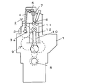
- the general valve mechanism 2 of the overhead valve engine 1 is mainly composed of a camshaft 3, a push rod 4, a rocker arm 5, a valve 6 and a valve spring 7. .
- the camshaft 3 is rotationally driven by a crankshaft 8 of the engine 1 via a gear mechanism 9, and the valve 6 is opened and closed by a cam 3 a of the camshaft 3 via a push rod 4 and a rocker arm 5. Yes.
- the piston 11 reciprocates in the cylinder 12 through the connecting rod 10 by the rotation of the crankshaft 8, and the intake system or exhaust system valve 6 is opened in accordance with the timing of the piston 11. A process is to be performed.
- the present invention has been made in view of the above circumstances, and can set an optimum valve timing at the engine speed, and can improve the air charging efficiency in the cylinder.
- the purpose is to provide a mechanism.
- the present invention relates to an overhead valve type engine in which a valve is pushed down by a camshaft cam via a push rod and a rocker arm, and the push rod is interposed between the cam and the push rod.
- a variable lift amount mechanism for changing the lift amount is provided.
- the lift amount varying mechanism has a female threaded portion at the shaft center, a pinion that is lifted and lowered by the cam, and a male threaded portion that is screwed to the female threaded portion of the pinion at the base end, and the push rod
- a connecting rod that connects the base end of the pinion, and a pinion that rotates with a variable rod that changes the amount of protrusion of the tip from the pinion by rotation of the pinion and a rack that meshes with the pinion. It is preferable to include a drive unit that varies the protruding amount of the variable rod by moving the variable rod.
- the pinion has a bottomed cylindrical shape with a closed lower end, and the internal thread portion is formed on the inner periphery of a shaft hole formed in the shaft center of the pinion, and the variable rod is formed in the shaft hole. It is preferable that a spiral spring is provided to press against the tip of the male screw portion and prevent rattling between the pinion and the variable rod.
- the drive unit is preferably an electric motor.
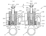
- FIGS. 4A and 4B are diagrams showing a lift amount variable mechanism, in which FIG. 4A shows when the change amount of the lift amount is 0, and FIG. 4B shows the time when the change amount of the lift amount is maximum. It is a figure which shows the conventional overhead valve type engine schematically. It is a figure which shows the structure of the valve operating mechanism of the conventional overhead valve type engine.
- reference numeral 20 denotes a lift amount variable mechanism that constitutes a main part of a variable valve mechanism of an overhead valve engine, and this lift amount variable mechanism 20 constitutes a valve mechanism of an overhead valve engine. It is provided between the cam 3 a of the camshaft 3 and the push rod 4.
- a general valve operating mechanism of an overhead valve type engine is mainly composed of a camshaft 3, a push rod 4, a rocker arm 5, a valve 6 and a valve spring 7, as shown in FIGS. .
- the camshaft 3 is rotationally driven by a crankshaft 8 of an engine via a gear mechanism 9, and the valve 6 is opened and closed by a cam 3 a of the camshaft 3 via a push rod 4 and a rocker arm 5. .
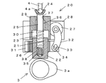
- the lift amount varying mechanism 20 has a female screw portion 21 at the shaft center, a pinion 22 that is lifted and lowered by the cam 3 a, and a male screw that is screwed into the female screw portion 21 of the pinion 22.
- a variable rod that has a portion 23 at the base end and a connecting portion 24 that connects the base end of the push rod 4 at the tip, and the amount of protrusion of the tip from the pinion 22 changes as the pinion 22 rotates.
- a drive unit for example, an electric motor 27, that varies the amount of protrusion of the variable rod 25 by rotating the pinion 22 via a rack 26 meshed with the pinion 22.
- the electric motor 27 may be a geared motor.
- the lift variable mechanism 20 includes a main body 28 for mounting the electric motor 27.
- the main body 28 is provided with a support portion 29 that slidably supports the variable rod 25, and the support portion 29 is formed with a recess 30 that can accommodate the upper side of the pinion 22.
- the main body 28 is provided with a rack support groove 31 that supports the rack 26 slidably in the horizontal direction below the support 29.
- the rotating shaft of the electric motor 27 is provided with a base end portion of an arc-shaped arm 32 curved toward the pinion 22, and one end of the rack 26 is connected to the tip end portion of the arm 32 via a pin 33.
- a long hole 34 that allows the movement of the pins 33 is provided at the tip of the arm 32.
- the pinion 22 has a bottomed cylindrical shape with its lower end closed, and a female screw portion 21 is formed on the inner periphery of a shaft hole 35 formed in the shaft center.
- the shaft hole 35 is provided with a helical spring 38 that presses against the tip of the male threaded portion 23 of the variable rod 25 to prevent rattling between the pinion 22 and the variable rod 25.
- variable rod 25 is provided with a key 36, and the support portion 29 is provided with a key groove 37 in which the key 36 is movably engaged in the axial direction.
- a spherical head 4a is provided at the lower end of the push rod 4, and the connecting portion 24 provided at the tip of the variable rod 25 is concave so as to be able to rotatably support the spherical head 4a. Is formed.
- variable valve mechanism of the overhead valve engine having the above configuration As shown in FIGS. 2 to 3A, the pinion 22 of the lift amount variable mechanism 20 is driven up and down by the rotation of the cam 3a of the camshaft 3, and the vertical movement of the pinion 22 is pushed through the variable rod 25 as a push rod. 4 and the valve 6 is opened and closed via the rocker arm 5. In this state, since the amount of protrusion of the variable rod 25 from the pinion 22 has not changed, the lift amount of the push rod 4 is constant, and the change amount x of the lift amount is zero.
- the rack 26 When the lift amount is changed, the rack 26 is moved from the non-operating position, which is the left standby position, to the right operating position via the arm 32 by driving the electric motor 27 as shown in FIG.
- the pinion 22 meshed with the rack 26 may be rotated around its axis. Since the rotation of the variable rod 25 in which the male screw portion 23 is screwed to the female screw portion 21 of the pinion 22 is restricted by the key 36 and the key groove 37, the screw is fed by the rotation of the pinion 22 and protrudes upward. As a result, the lift amount of the push rod 4 is changed, and the change amount x of the lift amount is maximized.
- the lift amount of the push rod 4 can be varied at the time of valve operation, whereby the opening / closing timing of the valve 6 can be varied.
- the lift amount variable mechanism 20 for changing the lift amount of the push rod 4 is provided between the cam 3 a and the push rod 4.
- the lift amount variable mechanism 20 for changing the lift amount of the push rod 4 is provided between the cam 3 a and the push rod 4.
- the lift amount varying mechanism 20 has a female threaded portion 21 at the shaft center, and has a pinion 22 that is moved up and down by the cam 3a and a male threaded portion 23 that is screwed to the female threaded portion 21 of the pinion 22 at the base end. And a connecting portion 24 that connects the base end portion of the push rod 4 at the distal end portion, and is engaged with the pinion 22 and a variable rod 25 that changes the protruding amount of the distal end portion from the pinion 22 by the rotation of the pinion 22. Since the electric motor 27 that is a drive unit that varies the protruding amount of the variable rod 25 by rotating the pinion 22 via the rack 26 is provided, the variable valve mechanism can be configured with a simple configuration. it can.
- the drive unit that drives the rack is not limited to an electric motor, and may be a fluid pressure cylinder, for example.
Landscapes
- Engineering & Computer Science (AREA)
- Mechanical Engineering (AREA)
- General Engineering & Computer Science (AREA)
- Valve Device For Special Equipments (AREA)
Abstract
エンジンの回転数における最適なバルブタイミングを設定することができ、シリンダ内の空気充填効率の向上が図れるオーバーヘッドバルブ式エンジンの可変動弁機構を提供する。 カムシャフト3のカム3aによりプッシュロッド4及びロッカーアーム5を介してバルブ6を押し下げる方式のオーバーヘッドバルブ式エンジン1の可変動弁機構であって、カム3aとプッシュロッド4との間にプッシュロッド4のリフト量を変えるためのリフト量可変機構20を設ける。
Description
本発明は、オーバーヘッドバルブ式エンジンの可変動弁機構に係り、特に一般的な動弁機構を可変動弁機構に改良する技術に関するものである。
図4ないし図5に示すように、オーバーヘッドバルブ式エンジン1の一般的な動弁機構2は、主にカムシャフト3、プッシュロッド4、ロッカーアーム5、バルブ6及びバルブスプリング7により構成されている。カムシャフト3は、エンジン1のクランクシャフト8により歯車機構9を介して回転駆動され、カムシャフト3のカム3aによりプッシュロッド4及びロッカーアーム5を介してバルブ6が開閉操作されるようになっている。
クランクシャフト8の回転によりコンロッド10を介してピストン11がシリンダ12内で往復運動を行い、ピストン11のタイミングに合わせて吸気系又は排気系のバルブ6が開弁されることにより、吸気工程又は排気工程が行われるようになっている。
しかしながら、従来のオーバーヘッドバルブ式エンジン1においては、バルブ6のリフト量が固定されているため、エンジン回転数におけるシリンダ内の最適な空気充填効率が得られなかった。そのため、エンジン回転数における最適なバルブタイミングを設定することが課題になっている。
本発明は、前記事情を考慮してなされたものであり、エンジンの回転数における最適なバルブタイミングを設定することができ、シリンダ内の空気充填効率の向上が図れるオーバーヘッドバルブ式エンジンの可変動弁機構を提供することを目的とする。
前記目的を達成するために、本発明は、カムシャフトのカムによりプッシュロッド及びロッカーアームを介してバルブを押し下げる方式のオーバーヘッドバルブ式エンジンにおいて、前記カムと前記プッシュロッドとの間に前記プッシュロッドのリフト量を変えるためのリフト量可変機構を設けたことを特徴とする。
前記リフト量可変機構は、軸心に雌ねじ部を有し、前記カムによって昇降されるピニオンと、該ピニオンの前記雌ねじ部に螺合される雄ねじ部を基端部に有し、且つ前記プッシュロッドの基端部を接続する接続部を先端部に有し、前記ピニオンの回動により前記ピニオンからの先端部の突出量が変わる可変ロッドと、前記ピニオンに噛合されるラックを介してピニオンを回動させることにより前記可変ロッドの突出量を可変する駆動部とを備えていることが好ましい。
前記ピニオンは、下端部が閉塞された有底円筒状であり、前記ピニオンの軸心に形成された軸孔の内周に前記雌ねじ部が形成されており、前記軸孔には、前記可変ロッドの前記雄ねじ部の先端部に圧接して前記ピニオンと前記可変ロッドとの間のガタツキを防止するための螺旋ばねが設けられていることが好ましい。
前記駆動部は、電動モータであることが好ましい。
本発明によれば、エンジンの回転数における最適なバルブタイミングを設定することが可能となり、シリンダ内の空気充填効率の向上が図れる。
以下に、本発明を実施するための形態を添付図面に基いて詳述する。
図1ないし図2において、20はオーバーヘッドバルブ式エンジンの可変動弁機構の要部を構成するリフト量可変機構であり、このリフト量可変機構20は、オーバーヘッドバルブ式エンジンの動弁機構を構成するカムシャフト3のカム3aとプッシュロッド4との間に設けられる。なお、オーバーヘッドバルブ式エンジンの一般的な動弁機構は、図4ないし図5に示すように、主にカムシャフト3、プッシュロッド4、ロッカーアーム5、バルブ6及びバルブスプリング7により構成されている。カムシャフト3は、エンジンのクランクシャフト8により歯車機構9を介して回転駆動され、カムシャフト3のカム3aによりプッシュロッド4及びロッカーアーム5を介してバルブ6が開閉操作されるようになっている。
リフト量可変機構20は、図1ないし図2に示すように、軸心に雌ねじ部21を有し、カム3aによって昇降されるピニオン22と、このピニオン22の雌ねじ部21に螺合される雄ねじ部23を基端部に有し、且つプッシュロッド4の基端部を接続する接続部24を先端部に有し、ピニオン22の回動によりピニオン22からの先端部の突出量が変わる可変ロッド25と、ピニオン22に噛合されるラック26を介してピニオン22を回動させることにより可変ロッド25の突出量を可変する駆動部例えば電動モータ27とを備えている。なお、電動モータ27はギヤ付モータであってもよい。
また、リフト量可変機構20は、電動モータ27を取付けるための本体28を備えている。この本体28には、可変ロッド25を摺動可能に支持する支持部29が設けられ、この支持部29にはピニオン22の上部側を収容可能な凹部30が形成されている。また、本体28には、支持部29よりも下方にラック26を水平方向にスライド可能に支持するラック用支持溝部31が設けられている。
電動モータ27の回転軸にはピニオン22側に湾曲した円弧状のアーム32の基端部が設けられ、このアーム32の先端部にはラック26の一端がピン33を介して連結されている。なお、ピン33との干渉を回避してラック26の円滑な動きを確保するために、アーム32の先端部にはピン33の移動を許容する長穴34が設けられている。
ピニオン22は、下端部が閉塞された有底円筒状であり、その軸心に形成された軸孔35の内周に雌ねじ部21が形成されている。また、軸孔35には可変ロッド25の雄ねじ部23の先端部に圧接してピニオン22と可変ロッド25との間のガタツキを防止するための螺旋ばね38が設けられている。
可変ロッド25の回転を防止するために、可変ロッド25にはキー36が設けられ、支持部29にはキー36が軸方向に移動可能に係合するキー溝37が設けられている。また、プッシュロッド4の下端部には球頭部4aが設けられ、可変ロッド25の先端部に設けられた接続部24はその球頭部4aを回動可能に支持し得るように凹面状に形成されている。
次に、以上の構成からなるオーバーヘッドバルブ式エンジンの可変動弁機構の作用を説明する。図2ないし図3(a)に示すようにカムシャフト3のカム3aの回転によりリフト量可変機構20のピニオン22が上下に駆動され、このピニオン22の上下動が可変ロッド25を介してプッシュロッド4に伝達され、ロッカーアーム5を介してバルブ6が開閉される。この状態では、ピニオン22からの可変ロッド25の突出量が変化していないため、プッシュロッド4のリフト量は一定で、リフト量の変化量xは0となる。
前記リフト量を変化させる場合には、図3(b)に示すように電動モータ27の駆動によりアーム32を介してラック26を左方の待機位置である非作動位置から右方の作動位置に引き動かし、このラック26に噛合しているピニオン22をその軸心回りに回動させればよい。このピニオン22の雌ねじ部21に雄ねじ部23が螺合している可変ロッド25はキー36とキー溝37によって回転が規制されているため、ピニオン22の回転によりねじ送りされて上方に突出する。これによりプッシュロッド4のリフト量が変化し、リフト量の変化量xが最大となる。
このようにして動弁時にプッシュロッド4のリフト量を可変することができ、これによりバルブ6の開閉タイミングを可変することができる。
従って、本実施形態に係るオーバーヘッドバルブ式エンジンの可変動弁機構によれば、カム3aとプッシュロッド4との間にプッシュロッド4のリフト量を変えるためのリフト量可変機構20を設けているため、エンジンの回転数における最適なバルブタイミングを設定することが可能となり、シリンダ内の空気充填効率の向上が図れる。
また、リフト量可変機構20は、軸心に雌ねじ部21を有し、カム3aによって昇降されるピニオン22と、このピニオン22の雌ねじ部21に螺合される雄ねじ部23を基端部に有し、且つプッシュロッド4の基端部を接続する接続部24を先端部に有し、ピニオン22の回動によりピニオン22からの先端部の突出量が変わる可変ロッド25と、ピニオン22に噛合されるラック26を介してピニオン22を回動させることにより可変ロッド25の突出量を可変する駆動部である電動モータ27とを備えているため、簡単な構成で可変動弁機構を構成することができる。
以上、本発明の実施の形態を図面により詳述してきたが、本発明は前記実施の形態に限定されるものではなく、本発明の要旨を逸脱しない範囲での種々の設計変更が可能である。ラックを駆動する駆動部としては、電動モータに限定されず、例えば流体圧シリンダであってもよい。
1 オーバーヘッドバルブ式エンジン
4 プッシュロッド
20 リフト量可変機構
21 雌ねじ部
22 ピニオン
23 雄ねじ部
24 接続部
25 可変ロッド
26 ラック
27 電動モータ(駆動部)
35 軸孔
38 螺旋ばね
4 プッシュロッド
20 リフト量可変機構
21 雌ねじ部
22 ピニオン
23 雄ねじ部
24 接続部
25 可変ロッド
26 ラック
27 電動モータ(駆動部)
35 軸孔
38 螺旋ばね
Claims (4)
- カムシャフトのカムによりプッシュロッド及びロッカーアームを介してバルブを押し下げる方式のオーバーヘッドバルブ式エンジンの可変動弁機構であって、前記カムと前記プッシュロッドとの間に前記プッシュロッドのリフト量を変えるためのリフト量可変機構を設けたことを特徴とするオーバーヘッドバルブ式エンジンの可変動弁機構。
- 前記リフト量可変機構は、軸心に雌ねじ部を有し、前記カムによって昇降されるピニオンと、該ピニオンの前記雌ねじ部に螺合される雄ねじ部を基端部に有し、且つ前記プッシュロッドの基端部を接続する接続部を先端部に有し、前記ピニオンの回動により前記ピニオンからの先端部の突出量が変わる可変ロッドと、前記ピニオンに噛合されるラックを介してピニオンを回動させることにより前記可変ロッドの突出量を可変する駆動部とを備えたことを特徴とする請求項1記載のオーバーヘッドバルブ式エンジンの可変動弁機構。
- 前記ピニオンは、下端部が閉塞された有底円筒状であり、前記ピニオンの軸心に形成された軸孔の内周に前記雌ねじ部が形成されており、前記軸孔には、前記可変ロッドの前記雄ねじ部の先端部に圧接して前記ピニオンと前記可変ロッドとの間のガタツキを防止するための螺旋ばねが設けられていることを特徴とする請求項2記載のオーバーヘッドバルブ式エンジンの可変動弁機構。
- 前記駆動部は、電動モータであることを特徴とする請求項2記載のオーバーヘッドバルブ式エンジンの可変動弁機構。
Applications Claiming Priority (2)
| Application Number | Priority Date | Filing Date | Title |
|---|---|---|---|
| JP2010033873A JP5458940B2 (ja) | 2010-02-18 | 2010-02-18 | オーバーヘッドバルブ式エンジンの可変動弁機構 |
| JP2010-033873 | 2010-02-18 |
Publications (1)
| Publication Number | Publication Date |
|---|---|
| WO2011102253A1 true WO2011102253A1 (ja) | 2011-08-25 |
Family
ID=44482840
Family Applications (1)
| Application Number | Title | Priority Date | Filing Date |
|---|---|---|---|
| PCT/JP2011/052516 Ceased WO2011102253A1 (ja) | 2010-02-18 | 2011-02-07 | オーバーヘッドバルブ式エンジンの可変動弁機構 |
Country Status (2)
| Country | Link |
|---|---|
| JP (1) | JP5458940B2 (ja) |
| WO (1) | WO2011102253A1 (ja) |
Cited By (1)
| Publication number | Priority date | Publication date | Assignee | Title |
|---|---|---|---|---|
| US20140245979A1 (en) * | 2013-03-04 | 2014-09-04 | Caterpillar Inc. | Variable valve timing arrangement |
Citations (6)
| Publication number | Priority date | Publication date | Assignee | Title |
|---|---|---|---|---|
| JPS56159603U (ja) * | 1980-04-28 | 1981-11-28 | ||
| JPS6216708U (ja) * | 1985-07-15 | 1987-01-31 | ||
| JPS62162708A (ja) * | 1985-08-23 | 1987-07-18 | Yanmar Diesel Engine Co Ltd | 内燃機関の弁開閉時期調整装置 |
| JPH0791215A (ja) * | 1993-09-24 | 1995-04-04 | Toyota Motor Corp | 内燃機関のバルブ装置 |
| JPH07166829A (ja) * | 1993-12-10 | 1995-06-27 | Komatsu Ltd | 弁装置 |
| JP2005325702A (ja) * | 2004-05-12 | 2005-11-24 | Toyota Motor Corp | 可変圧縮比内燃機関のバルブタイミング制御システム |
-
2010
- 2010-02-18 JP JP2010033873A patent/JP5458940B2/ja not_active Expired - Fee Related
-
2011
- 2011-02-07 WO PCT/JP2011/052516 patent/WO2011102253A1/ja not_active Ceased
Patent Citations (6)
| Publication number | Priority date | Publication date | Assignee | Title |
|---|---|---|---|---|
| JPS56159603U (ja) * | 1980-04-28 | 1981-11-28 | ||
| JPS6216708U (ja) * | 1985-07-15 | 1987-01-31 | ||
| JPS62162708A (ja) * | 1985-08-23 | 1987-07-18 | Yanmar Diesel Engine Co Ltd | 内燃機関の弁開閉時期調整装置 |
| JPH0791215A (ja) * | 1993-09-24 | 1995-04-04 | Toyota Motor Corp | 内燃機関のバルブ装置 |
| JPH07166829A (ja) * | 1993-12-10 | 1995-06-27 | Komatsu Ltd | 弁装置 |
| JP2005325702A (ja) * | 2004-05-12 | 2005-11-24 | Toyota Motor Corp | 可変圧縮比内燃機関のバルブタイミング制御システム |
Cited By (2)
| Publication number | Priority date | Publication date | Assignee | Title |
|---|---|---|---|---|
| US20140245979A1 (en) * | 2013-03-04 | 2014-09-04 | Caterpillar Inc. | Variable valve timing arrangement |
| US8967103B2 (en) * | 2013-03-04 | 2015-03-03 | Caterpillar Inc. | Variable valve timing arrangement |
Also Published As
| Publication number | Publication date |
|---|---|
| JP2011169238A (ja) | 2011-09-01 |
| JP5458940B2 (ja) | 2014-04-02 |
Similar Documents
| Publication | Publication Date | Title |
|---|---|---|
| JP6806536B2 (ja) | 連続可変バルブデュレーション装置およびこれを含むエンジン | |
| US10138764B2 (en) | Continuous variable valve duration apparatus and engine provided with the continuous variable valve duration apparatus | |
| US20120055428A1 (en) | Variable valve actuation apparatus for internal combustion engine | |
| US20110107998A1 (en) | Engine With Variable Compression Ratio | |
| CN105697094A (zh) | 连续可变气门打开持续时间装置及设有该装置的发动机 | |
| JP7215868B2 (ja) | 連続可変バルブデュレーション装置およびこれを含むエンジン | |
| KR101655227B1 (ko) | 연속 가변 밸브 듀레이션 장치 및 이를 포함하는 엔진 | |
| KR102440614B1 (ko) | 연속 가변 밸브 듀레이션 장치 및 이를 포함하는 엔진 | |
| WO2010108374A1 (zh) | 气门升程可调的发动机配气机构 | |
| CN101705851B (zh) | 机械式连续可变气门升程驱动装置 | |
| JP5458940B2 (ja) | オーバーヘッドバルブ式エンジンの可変動弁機構 | |
| US7458349B2 (en) | Valve train apparatus for 4 stroke-cycle internal combustion engine | |
| CN202866918U (zh) | 一种发动机可变气门升程机构 | |
| CN106762008B (zh) | 一种连续可变气门驱动装置及其控制方法 | |
| CN201810360U (zh) | 发动机连续可变气门驱动装置 | |
| JP6993828B2 (ja) | 連続可変バルブデュレーション装置およびこれを含むエンジン | |
| CN107762587B (zh) | 执行机构、可变气门升程装置、发动机及汽车 | |
| KR101675511B1 (ko) | 엔진의 가변밸브 리프트 장치 | |
| CN102943699B (zh) | 用于内燃机的凸轮摇臂机构 | |
| CN101963077A (zh) | 发动机连续可变气门驱动装置 | |
| CN103352736A (zh) | 一种连续可变气门升程机构 | |
| JP5617274B2 (ja) | 可変バルブタイミング機構 | |
| JP2016079858A (ja) | エンジンの吸排気弁の動弁構造 | |
| CN209067300U (zh) | 一种摇臂机构及发动机 | |
| CN109519248B (zh) | 电控气门机构、发动机及汽车 |
Legal Events
| Date | Code | Title | Description |
|---|---|---|---|
| 121 | Ep: the epo has been informed by wipo that ep was designated in this application |
Ref document number: 11744540 Country of ref document: EP Kind code of ref document: A1 |
|
| NENP | Non-entry into the national phase |
Ref country code: DE |
|
| 122 | Ep: pct application non-entry in european phase |
Ref document number: 11744540 Country of ref document: EP Kind code of ref document: A1 |