WO2011102179A1 - 電池状態検知装置 - Google Patents
電池状態検知装置 Download PDFInfo
- Publication number
- WO2011102179A1 WO2011102179A1 PCT/JP2011/050961 JP2011050961W WO2011102179A1 WO 2011102179 A1 WO2011102179 A1 WO 2011102179A1 JP 2011050961 W JP2011050961 W JP 2011050961W WO 2011102179 A1 WO2011102179 A1 WO 2011102179A1
- Authority
- WO
- WIPO (PCT)
- Prior art keywords
- battery
- secondary battery
- voltage
- charging
- open
- Prior art date
- Legal status (The legal status is an assumption and is not a legal conclusion. Google has not performed a legal analysis and makes no representation as to the accuracy of the status listed.)
- Ceased
Links
Images



Classifications
-
- G—PHYSICS
- G01—MEASURING; TESTING
- G01R—MEASURING ELECTRIC VARIABLES; MEASURING MAGNETIC VARIABLES
- G01R31/00—Arrangements for testing electric properties; Arrangements for locating electric faults; Arrangements for electrical testing characterised by what is being tested not provided for elsewhere
- G01R31/36—Arrangements for testing, measuring or monitoring the electrical condition of accumulators or electric batteries, e.g. capacity or state of charge [SoC]
- G01R31/382—Arrangements for monitoring battery or accumulator variables, e.g. SoC
- G01R31/3835—Arrangements for monitoring battery or accumulator variables, e.g. SoC involving only voltage measurements
Definitions
- the present invention relates to a battery state detection device that detects the state of a secondary battery.
- Patent Document 1 describes that “a change in battery voltage accompanying a change in battery current has a certain delay, and the battery voltage stabilizes after a certain period of time called relaxation time”.
- the charge rate may be estimated.
- an object of the present invention is to provide a battery state detection device that can accurately calculate the charging rate of a secondary battery.
- a battery state detection device includes: Voltage detection means for detecting an open voltage of the secondary battery; The open voltage after charging of the secondary battery detected by the voltage detection means is applied to the first battery characteristic indicating the relationship between the open voltage after charging of the secondary battery and the charging rate of the secondary battery. Then, the charge rate is calculated, and the open circuit voltage after discharging the secondary battery detected by the voltage detecting means is calculated as the open circuit voltage after discharging the secondary battery and the charge rate of the secondary battery. It is applied to the 2nd battery characteristic which shows a relationship, The charging rate calculation means which calculates the said charging rate is provided, It is characterized by the above-mentioned.
- the charging rate of the secondary battery can be calculated with high accuracy.
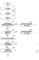
- FIG. 6 is a diagram illustrating an operation flow of a calculation unit 24.
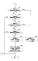
- FIG. 6 is a diagram illustrating an operation flow of a calculation unit 24.
- FIG. 6 is a diagram showing an “open circuit voltage-ambient temperature” characteristic.
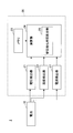
- FIG. 1 is an overall configuration diagram of a battery monitoring system 1 including a battery state detection device 20 according to an embodiment of the present invention.
- the battery monitoring system 1 includes a secondary battery 10 and a battery state detection device 20 that detects the state of the secondary battery 10.
- the secondary battery 10 include a lithium ion battery and a nickel metal hydride battery.
- the battery state detection device 20 includes a voltage detector 21, a temperature detector 22, a memory 23, and a calculation unit 24.
- the battery state detection device 20 may include a current detector 27 that detects a charge / discharge current (input / output current) of the secondary battery 10.
- These components of the battery state detection device 20 such as the voltage detector 21 are configured by, for example, an integrated circuit.
- the voltage detector 21 is voltage detection means for detecting the output voltage of the secondary battery 10.
- the voltage detector 21 outputs detection data of the output voltage of the secondary battery 10 to the calculation unit 24.
- the voltage detector 21 is a secondary battery 10 in a state in which the charge / discharge current (input / output current) of the secondary battery 10 is at least a predetermined first threshold value (for example, zero or a value slightly larger than zero). Is detected as an open circuit voltage of the secondary battery 10.
- the voltage detector 21 is a voltage between the electrodes measured with a high impedance or between the electrodes of the stable secondary battery 10 or an external device (for example, the secondary battery 10 and the battery state detection device 20 is connected). The voltage between both electrodes measured with a load of a standby state current (for example, 1 mA or less) of a portable device such as a mobile phone or a game machine may be detected as the open voltage of the secondary battery 10.
- the temperature detector 22 is temperature detecting means for detecting the ambient temperature Ta of the secondary battery 10.
- the temperature detector 22 outputs detection data of the ambient temperature Ta of the secondary battery 10 to the calculation unit 24.
- the temperature detector 22 may detect the temperature of the secondary battery 10 itself as the ambient temperature Ta.
- the calculation unit 24 is based on the voltage detection data from the voltage detector 21, the temperature detection data from the temperature detector 22, and the battery characteristics specific to the secondary battery 10 stored in advance in the memory 23. It is an estimation means for estimating the state (in particular, the charging rate).
- a specific example of the calculation unit 24 is a microcomputer incorporating a central processing unit and the like.
- Specific examples of the memory 23 that holds the characteristic parameters for specifying the battery characteristics of the secondary battery 10 include an EEPROM and a flash memory.
- the calculating unit 24 includes a stable waiting time calculating unit 26 as a stable waiting time calculating means for calculating a stable waiting time T required for stabilizing the output voltage of the secondary battery 10.
- the stabilization waiting time T is determined after the discharge current (or the charging current) of the secondary battery 10 becomes equal to or less than a predetermined first threshold (for example, zero or a value slightly larger than zero). This is a waiting time until the voltage change amount per unit time becomes equal to or less than a predetermined second threshold (for example, zero or an amount slightly larger than zero). That is, the voltage stable state in which the output voltage of the secondary battery 10 is stable is a state in which the discharge current (or the charging current) of the secondary battery 10 is equal to or less than a predetermined first threshold value.
- the stabilization waiting time calculation unit 26 is configured to calculate detected values such as output voltage, charge / discharge current and ambient temperature of the secondary battery 10, and calculated values of capacity retention rate (deterioration rate) that can be derived based on these detected values. Based on at least one of them, it is preferable to calculate the stabilization waiting time T until the transition to the voltage stable state by the timer (time measuring means) of the calculation unit 24.
- a method for calculating the stable waiting time T a known method can be used, and there is no particular limitation.
- the calculation unit 24 indicates the relationship between the open-circuit voltage after charging the secondary battery 10 and the charge rate of the secondary battery 10 with respect to the open-circuit voltage after charging the secondary battery 10 detected by the voltage detector 21. Applying to the first battery characteristics, the charging rate of the secondary battery 10 is calculated, and the open-circuit voltage after discharge of the secondary battery 10 detected by the voltage detector 21 is used as the open-circuit after discharge of the secondary battery 10. It is a charging rate calculation means for calculating the charging rate of the secondary battery 10 by applying it to the second battery characteristic indicating the relationship between the voltage and the charging rate 10 of the secondary battery. First characteristic data for specifying the first battery characteristic and second characteristic data for specifying the second battery characteristic are stored in the memory 23 in advance.
- the charging rate means a percentage of the remaining capacity of the secondary battery 10 when the full charge capacity of the secondary battery 10 at that time is 100.
- the battery characteristics indicating the correlation between “open circuit voltage and charging rate” necessary for calculating the charging rate are represented by a correction table or a correction function. Data in the correction table and coefficients of the correction function are stored in the memory 23 as characteristic data.
- the calculation unit 24 calculates and corrects the charging rate according to the open circuit voltage measured by the voltage detector 21 based on the correction table and the correction function reflecting the characteristic data read from the memory 23.
- the characteristic data determined based on the result (see FIG. 2) obtained by actually measuring the correlation with “open circuit voltage ⁇ charge rate” is stored in the memory 23.
- the characteristic graph “a” is actual measurement data obtained by repeatedly performing no load for a predetermined time (4 hours) every time a predetermined amount (50 mAh) is charged from the state where the remaining capacity is 0 mAh.
- the voltage between both electrodes increases during charging, and the open circuit voltage decreases in the state of a1, a2, a3,.
- the information of “open voltage ⁇ charge rate” in the no-load state for 4 hours after charging is stored in the memory 23 as open voltage data for each charge rate after the secondary battery 10 is charged.
- the characteristic graph c connects the open circuit voltage in a no-load state for 4 hours after charge.
- the characteristic graph b is actual measurement data obtained when a no-load is repeatedly performed for a predetermined time (4 hours) every time a predetermined amount (50 mAh) is discharged from a fully charged state.
- the open circuit voltage decreases during discharge, and the open circuit voltage increases in the state of b1, b2, b3.
- the information of “open voltage ⁇ charge rate” in the no-load state for 4 hours after discharge is stored in the memory 23 as open voltage data for each charge rate after discharge of the secondary battery 10.
- the characteristic graph d connects the open circuit voltage in a no-load state for 4 hours after discharge.
- the characteristic graph d substantially overlaps the characteristic graph e when the battery is always discharged at 3 mA from the fully charged state.
- Both the open-circuit voltage data for each charge rate after charging and the open-circuit voltage data for each charge rate after discharge stored in the memory 23 may be voltage data obtained by measurement. Either one of the open-circuit voltage data for each charging rate and the open-circuit voltage data for each charging rate after discharging may be represented by voltage data specified by a difference from the other. That is, for any one of the open-circuit voltage data, the value of the measured voltage may not be stored in the memory 23 as it is. Thereby, the storage capacity required for the memory 23 can be reduced.
- the calculation unit 24 can calculate the other open-circuit voltage data based on one of the open-circuit voltage data and the other differential voltage data.
- the difference voltage for each charging rate between the characteristic graph a and the characteristic graph b corresponds to voltage data of a difference between the open-circuit voltage data after charging and the open-circuit voltage data after discharging.
- the open-circuit voltage data after charging is stored as measured voltage data
- the open-circuit voltage data after discharging is stored as differential voltage data.
- the absolute value of the open-circuit voltage is in the unit of several volts
- the differential voltage is in the unit of several tens of mV.
- the open-circuit voltage after both charging and discharging is stored as its absolute value as compared with the case of storing the absolute voltage of the memory 23.
- the required storage capacity can be greatly reduced.
- the calculation unit 24 stores, for example, an open voltage data group for each charging rate after charging according to the discharge capacity from the end of charging of the secondary battery 10 and the elapsed time from the end of charging of the secondary battery 10.
- the “charge side table” and the “discharge side table” in which the open voltage data group for each charge rate after discharge is stored are selected. Then, the charging rate is calculated based on the selected table.
- FIG. 3 is a diagram illustrating a period during which the charge side table or the discharge side table is selectively applied.
- the charging period of the secondary battery 10 corresponds to a period from the charging start time t1 to the charging end time t2.
- the calculation unit 24 stabilizes the output voltage of the secondary battery 10 in a situation where no discharge exceeding the predetermined reference capacity A1 occurs due to no load or slight discharge after the end of charging t2.
- the open circuit voltage detected by the voltage detector 21 is The charging rate is calculated based on the charging side table, assuming that the "open voltage after charging".
- the load state after the charging end time t2 is not always unloaded, and depending on an external device (not shown) that uses the secondary battery 10 as a power source (for example, a mobile phone, a game machine, etc.) There may be a slight discharge state in which current consumption continues to flow. For this reason, it is considered inappropriate to treat the open circuit voltage detected when a certain amount of time has elapsed from the end of charge t2 as the “open circuit voltage after charging”. Therefore, the period during which the charging rate may be calculated based on the charging side table needs to be less than the predetermined reference time A2 from the time point t2 when charging ends.
- reference capacity A1 and the reference time A2 may be determined in accordance with the characteristics of the cell of the secondary battery 10 and the current consumption of an external device fed from the secondary battery 10.
- the calculation unit 24 uses either the discharge side table or the charge side table as a reference if a certain discharge amount or discharge time does not occur. This makes it difficult to determine whether an accurate charge rate can be calculated.
- the calculation unit 24 may have a constant discharge capacity (for example, a reference capacity B1 larger than the reference capacity A1) or a discharge time (for example, a reference capacity) according to the characteristics of the cells of the secondary battery 10 after the charging end time t2. By stopping the process of calculating the charging rate from the output voltage of the secondary battery 10 until the reference time B2) longer than the time A2 occurs, it is possible to prevent the charging rate calculation error from increasing.
- the calculation unit 24 after a charging end time t2, after a certain discharge capacity (for example, a reference capacity B1) is generated by a slight discharge (or from the charging end time t2). If the output voltage of the secondary battery 10 is still stable after the voltage stabilization start time t3 (after the elapsed time of the predetermined time B2 has elapsed), the open circuit voltage detected by the voltage detector 21 is “after discharge The charging rate is calculated based on the discharge side table. Further, as shown in FIG. 3B, the calculation unit 24 generates a constant discharge capacity (for example, the reference capacity B1) due to the large discharge (t13 to t14) exceeding the fine discharge after the charging end time t12.
- a constant discharge capacity for example, the reference capacity B1 due to the large discharge (t13 to t14) exceeding the fine discharge after the charging end time t12.
- the voltage detector 21 Assuming that the detected open circuit voltage is “open circuit voltage after discharge”, the charging rate is calculated based on the discharge side table. In FIG. 3B, a period from the discharge end time t14 to the voltage stabilization start time t15 corresponds to the above-described stabilization waiting time T.
- 4A and 4B are calculation process flows of the charging rate of the secondary battery 10.
- the calculation unit 24 starts an operation according to this flow.
- the calculation unit 24 measures the output voltage of the secondary battery 10 as an open voltage by the voltage detector 21 (step S11). Moreover, the calculating part 24 measures the charging / discharging electric current of the secondary battery 10 by the current detector 27 (step S13). Moreover, the calculating part 24 measures the ambient temperature of the secondary battery 10 with the temperature detector 22 (step S15). Steps S11 to S15 are not limited to this order.
- the stability waiting time calculation unit 26 when at least one of the ambient temperature Ta and the charge / discharge current of the secondary battery 10 fluctuates beyond a predetermined reference before the already calculated stability waiting time T elapses, The stable waiting time T is recalculated as described above using the value changed with the fluctuation, and the register value of the stable waiting time T is updated to the recalculated value (steps S17 to S23).
- the necessary stabilization waiting time T is reset at a time after the detection. Even if the fluctuation of the ambient temperature of the secondary battery 10 is stabilized, there is a time lag until the temperature of the secondary battery 10 itself is stabilized, so that the battery state such as the measured open-circuit voltage and battery temperature may not be stable. is there. Therefore, estimating the remaining capacity state of the secondary battery 10 based on the battery state such as the ambient temperature Ta or the ambient temperature Ta before the charge / discharge current fluctuates may increase the estimation error. However, by extending the stabilization waiting time T as in steps S17 to S23, such an increase in estimation error can be suppressed.
- step S17 when a change in the ambient temperature Ta exceeding a reference value is detected for a certain time after the charging / discharging current of the secondary battery 10 equal to or lower than a predetermined first threshold is detected in step S17, the process waits for stability.
- the time calculation unit 26 recalculates the stable waiting time T corresponding to the already calculated capacity retention ratio K and the ambient temperature Ta after the fluctuation, and updates the register value to the recalculated value (step S19).
- the charging / discharging current of the secondary battery 10 that is equal to or greater than a predetermined threshold is a condition for recalculating the stable waiting time T, and can also be a variable factor of the capacity retention rate K.
- the stable waiting time calculation unit 26 recalculates the stable waiting time T corresponding to the already measured ambient temperature K and the capacity retention rate K after the fluctuation, and updates the register value to the recalculated value (step S23). .
- the arithmetic unit 24 is configured to wait for a stable waiting time when neither the ambient temperature Ta nor the charge / discharge current of the secondary battery 10 exceeds a predetermined standard (for example, when the fluctuation is within a certain range).
- the register value of T is subtracted by a predetermined value (step S25), and it is determined whether or not the stabilization waiting time T has elapsed, that is, whether or not the register value of the stabilization waiting time T has become zero (step S27). If the stabilization waiting time T has not elapsed, the process returns to the beginning of this flow.
- the calculation unit 24 stabilizes the voltage after the stabilization waiting time T based on the characteristic data indicating the “open voltage-ambient temperature” characteristic (FIG. 5) stored in the memory 23 in advance.
- the open-circuit voltage measured in the voltage stable state after the stabilization waiting time T (or the open-circuit voltage measured in step S11). Is corrected to 25 ° C. (step S29).
- the “open-circuit voltage-ambient temperature” characteristic (FIG. 5) indicates the offset amount of the open-circuit voltage at each temperature with 25 ° C. as a reference.
- FIG. 5 shows the offset amount of the open circuit voltage for each charging rate of the secondary battery 10.
- the calculation unit 24 determines whether or not the discharge capacity from the end of charging is equal to or greater than a predetermined first reference capacity B1 (step S31).
- a predetermined first reference capacity B1 As shown in FIG. 3 (b), a large discharge occurs after the charging end time t2, and the load state of no load or slight discharge occurs after the occurrence. Since the output voltage is stabilized at the timing t15 by continuing, the “discharge side table” in which the relationship between the charge rate after discharge and the open circuit voltage is specified is selected as the charge rate calculation table (step S33).
- the calculation unit 24 calculates the charge rate corresponding to the open circuit voltage corrected to the 25 ° C. condition in step S29 to the remaining capacity of the secondary battery 10. The state is calculated and the register value of the charging rate is updated to the calculated value (step S43).
- step S31 when it is determined that the calculation unit 24 is not greater than or equal to the reference capacity B1, it is determined whether or not the discharge capacity from the end of charging is less than a predetermined second reference capacity A1 (step S35). .
- the reference capacity A1 is smaller than the reference capacity B1.
- the calculation unit 24 determines that it is not less than the reference capacity A1, the amount of discharge from the charging end time t2 is large, and the open circuit voltage detected by the voltage detector 21 is the open circuit voltage after discharge or the open circuit voltage after charging. It is difficult to distinguish between the charging rate and the register value of the charging rate is not updated.
- step S35 when it is determined that the calculation unit 24 is less than the reference capacity A1, the calculation unit 24 determines whether or not the elapsed time from the end of charging is equal to or longer than a predetermined first reference time B2 (step S37). If the calculation unit 24 determines that the reference time B2 or more, the open-circuit voltage detected by the voltage detector 21 is “open-circuit voltage after discharge” and selects the discharge-side table as the charging rate calculation table (step S ⁇ b> 2). S33).
- the subsequent processing in step S43 is the same as described above. For example, in the situation of FIG. 3A, the discharge side table is selected in the period from the time t5 when the reference time B2 elapses to the voltage unstable time t6, and in the situation of FIG.
- the discharge side table is selected during the period from time t15 to voltage instability time t16.
- the voltage unstable time t6 or t16 is a time when the charging / discharging current exceeds a predetermined value at which the open circuit voltage can be considered unstable.
- step S35 determines that the discharge time is less than the reference time B2 in step S37, is the discharge capacity from the end of charging less than the predetermined second reference time A2? It is determined whether or not (step S39).
- the reference time A2 is shorter than the reference time B2.
- step S39 when the calculation unit 24 determines that it is less than the reference time A2, the open-side voltage detected by the voltage detector 21 is “open-circuit voltage after charging” and the charge-side table is used for calculating the charging rate.
- Select as a table step S41). For example, in the situation of FIG. 3A, the charging side table is selected in the period from the voltage stabilization time t3 to the elapsed time t4 of the reference time A2.
- the calculation unit 24 calculates the charging rate corresponding to the open-circuit voltage corrected to the 25 ° C. condition in step S 29 as the remaining capacity of the secondary battery 10. The state is calculated, and the register value of the charging rate is updated to the calculated value (step S43).
- charging is performed by selectively measuring the open circuit voltage after charging and the open circuit voltage after discharging, and selectively applying the charging side table and the discharging side table as the charging rate calculation table. Regardless of the state after and after discharge, an accurate charging rate can always be calculated.
- the characteristic graph c in the no-load state after charging and / or the characteristic graph d in the no-load state after discharging are represented by an approximate model function of a polynomial by curve fitting processing, and each coefficient of the polynomial May be stored in the memory 23 in advance.
- the storage capacity of the memory 23 can be reduced compared with the case where the open circuit voltage data for each charging rate is stored as it is.
Landscapes
- Physics & Mathematics (AREA)
- General Physics & Mathematics (AREA)
- Secondary Cells (AREA)
- Charge And Discharge Circuits For Batteries Or The Like (AREA)
- Tests Of Electric Status Of Batteries (AREA)
Abstract
Description
二次電池の開放電圧を検出する電圧検出手段と、
前記電圧検出手段によって検出された前記二次電池の充電後の開放電圧を、前記二次電池の充電後の開放電圧と前記二次電池の充電率との関係を示す第1の電池特性に適用して、前記充電率を算出し、前記電圧検出手段によって検出された前記二次電池の放電後の開放電圧を、前記二次電池の放電後の開放電圧と前記二次電池の充電率との関係を示す第2の電池特性に適用して、前記充電率を算出する、充電率算出手段とを備えることを特徴とするものである。
10 二次電池
20 電池状態検知装置
21 電圧検出器
22 温度検出器
23 メモリ
24 演算部
26 安定待ち時間算出部
27 電流検出器
Claims (10)
- 二次電池の開放電圧を検出する電圧検出手段と、
前記電圧検出手段によって検出された前記二次電池の充電後の開放電圧を、前記二次電池の充電後の開放電圧と前記二次電池の充電率との関係を示す第1の電池特性に適用して、前記充電率を算出し、前記電圧検出手段によって検出された前記二次電池の放電後の開放電圧を、前記二次電池の放電後の開放電圧と前記二次電池の充電率との関係を示す第2の電池特性に適用して、前記充電率を算出する、充電率算出手段とを備える、電池状態検知装置。 - 前記充電率算出手段は、前記二次電池の充電後の放電容量が第1の基準容量以上である場合、前記第2の電池特性の適用を選択して、前記充電率を算出する、請求項1に記載の電池状態検知装置。
- 前記充電率算出手段は、前記放電容量が前記第1の基準容量未満であり且つ前記二次電池の充電終了時点からの経過時間が第1の基準時間以上である場合、前記第2の電池特性の適用を選択して、前記充電率を算出する、請求項2に記載の電池状態検知装置。
- 前記充電率算出手段は、前記放電容量が前記第1の基準容量未満であり且つ前記経過時間が前記第1の基準時間未満である場合、前記第1の電池特性の適用を選択して、前記充電率を算出する、請求項3に記載の電池状態検知装置。
- 前記第1の電池特性を特定するための第1の特性データと前記第2の電池特性を特定するための第2の特性データを記憶する記憶手段を備え、
前記第1の特性データを構成する開放電圧データと前記第2の特性データを構成する開放電圧データのいずれか一方が、もう一方との差分の電圧データによって表される、請求項1に記載の電池状態検知装置。 - 二次電池の開放電圧を検出し、
前記検出された前記二次電池の充電後の開放電圧を、前記二次電池の充電後の開放電圧と前記二次電池の充電率との関係を示す第1の電池特性に適用して、前記充電率を算出し、
前記検出された前記二次電池の放電後の開放電圧を、前記二次電池の放電後の開放電圧と前記二次電池の充電率との関係を示す第2の電池特性に適用して、前記充電率を算出することを特徴とする電池状態検知方法。 - 前記二次電池の充電後の放電容量が第1の基準容量以上である場合、前記第2の電池特性の適用を選択して、前記充電率を算出することを特徴とする請求項6に記載の電池状態検知方法。
- 前記放電容量が前記第1の基準容量未満であり且つ前記二次電池の充電終了時点からの経過時間が第1の基準時間以上である場合、前記第2の電池特性の適用を選択して、前記充電率を算出することを特徴とする請求項7に記載の電池状態検知方法。
- 前記放電容量が前記第1の基準容量未満であり且つ前記経過時間が前記第1の基準時間未満である場合、前記第1の電池特性の適用を選択して、前記充電率を算出することを特徴とする請求項8に記載の電池状態検知方法。
- 前記第1の電池特性を特定するための第1の特性データと前記第2の電池特性を特定するための第2の特性データを記憶し、
前記第1の特性データを構成する開放電圧データと前記第2の特性データを構成する開放電圧データのいずれか一方が、もう一方との差分の電圧データによって表示することを特徴とする請求項6に記載の電池状態検知方法。
Priority Applications (2)
| Application Number | Priority Date | Filing Date | Title |
|---|---|---|---|
| CN201180009971.7A CN102762995B (zh) | 2010-02-19 | 2011-01-20 | 电池状态检测装置和电池状态检测方法 |
| US13/519,365 US20120290236A1 (en) | 2010-02-19 | 2011-01-20 | Battery condition detecting apparatus |
Applications Claiming Priority (2)
| Application Number | Priority Date | Filing Date | Title |
|---|---|---|---|
| JP2010-035128 | 2010-02-19 | ||
| JP2010035128A JP5732725B2 (ja) | 2010-02-19 | 2010-02-19 | 電池状態検知装置 |
Publications (1)
| Publication Number | Publication Date |
|---|---|
| WO2011102179A1 true WO2011102179A1 (ja) | 2011-08-25 |
Family
ID=44482780
Family Applications (1)
| Application Number | Title | Priority Date | Filing Date |
|---|---|---|---|
| PCT/JP2011/050961 Ceased WO2011102179A1 (ja) | 2010-02-19 | 2011-01-20 | 電池状態検知装置 |
Country Status (4)
| Country | Link |
|---|---|
| US (1) | US20120290236A1 (ja) |
| JP (1) | JP5732725B2 (ja) |
| CN (1) | CN102762995B (ja) |
| WO (1) | WO2011102179A1 (ja) |
Cited By (3)
| Publication number | Priority date | Publication date | Assignee | Title |
|---|---|---|---|---|
| CN103777146A (zh) * | 2012-10-24 | 2014-05-07 | 株式会社杰士汤浅国际 | 蓄电状态检测装置 |
| JP2019148492A (ja) * | 2018-02-27 | 2019-09-05 | トヨタ自動車株式会社 | 二次電池システム |
| JP2022545549A (ja) * | 2019-12-11 | 2022-10-27 | エルジー エナジー ソリューション リミテッド | バッテリー管理システム、バッテリーパック、電気車両及びバッテリー管理方法 |
Families Citing this family (23)
| Publication number | Priority date | Publication date | Assignee | Title |
|---|---|---|---|---|
| JP5870590B2 (ja) * | 2011-09-29 | 2016-03-01 | ミツミ電機株式会社 | 電池状態計測方法及び電池状態計測装置 |
| JP2013083612A (ja) * | 2011-10-12 | 2013-05-09 | Mitsumi Electric Co Ltd | 電池状態計測方法及び電池状態計測装置 |
| WO2013094126A1 (ja) * | 2011-12-22 | 2013-06-27 | パナソニック株式会社 | 電子機器及び電子機器充電システム |
| JP5768772B2 (ja) * | 2012-06-29 | 2015-08-26 | 株式会社豊田自動織機 | 蓄電システムおよび充電率推定方法 |
| TWI460453B (zh) * | 2012-09-28 | 2014-11-11 | Metal Ind Res & Dev Ct | 以兩個相互垂直的分量相加合成的電池殘電量估測系統及其估測方法 |
| CN102928785A (zh) * | 2012-10-16 | 2013-02-13 | 西安思坦仪器股份有限公司 | 电池电量测量仪及测量方法 |
| US9552031B2 (en) | 2013-12-20 | 2017-01-24 | Facebook, Inc. | Power shelf for computer servers |
| DE102014200673A1 (de) * | 2014-01-16 | 2015-07-16 | Robert Bosch Gmbh | Verfahren zum Überwachen einer Batterie |
| FR3025889B1 (fr) * | 2014-09-12 | 2016-11-18 | Commissariat Energie Atomique | Gestion de la recharge de la batterie d'un vehicule electrique |
| JP6490414B2 (ja) * | 2014-12-05 | 2019-03-27 | 古河電気工業株式会社 | 二次電池状態検出装置および二次電池状態検出方法 |
| US10386421B2 (en) * | 2015-09-14 | 2019-08-20 | Facebook, Inc. | Energy based battery backup unit testing |
| US10063092B2 (en) | 2015-10-02 | 2018-08-28 | Facebook, Inc. | Data center power network with multiple redundancies |
| US9986658B2 (en) | 2015-12-03 | 2018-05-29 | Facebook, Inc | Power connection clip for a shelf in a server rack |
| JP6830318B2 (ja) | 2016-01-15 | 2021-02-17 | 株式会社Gsユアサ | 蓄電素子管理装置、蓄電素子モジュール、車両および蓄電素子管理方法 |
| JP6930572B2 (ja) * | 2016-01-15 | 2021-09-01 | 株式会社Gsユアサ | 蓄電素子管理装置、蓄電素子モジュール、車両および蓄電素子管理方法 |
| US10123450B2 (en) | 2016-05-12 | 2018-11-06 | Facebook, Inc. | High voltage direct current power generator for computer server data centers |
| KR102458526B1 (ko) | 2018-02-07 | 2022-10-25 | 주식회사 엘지에너지솔루션 | 배터리의 동작 상태에 따라 soc를 추정하는 장치 및 방법 |
| JP7111969B2 (ja) | 2018-10-30 | 2022-08-03 | ミツミ電機株式会社 | 電子機器及びその制御方法 |
| JP7044044B2 (ja) * | 2018-12-07 | 2022-03-30 | トヨタ自動車株式会社 | 二次電池の劣化度推定装置および二次電池の劣化度推定方法 |
| JP7244746B2 (ja) | 2019-02-22 | 2023-03-23 | ミツミ電機株式会社 | 電子機器及びその状態判定方法 |
| JP7396813B2 (ja) * | 2019-06-06 | 2023-12-12 | パナソニック インテレクチュアル プロパティ コーポレーション オブ アメリカ | 開回路電圧計測方法、開回路電圧計測装置、及びプログラム |
| CN111308357B (zh) * | 2020-04-01 | 2022-10-28 | 一汽解放汽车有限公司 | 电池容量估算方法、电池管理系统、车辆及存储介质 |
| CN117317418B (zh) * | 2023-11-29 | 2024-02-13 | 珠海智锐科技有限公司 | 一种bms管理系统的电池控制方法 |
Citations (2)
| Publication number | Priority date | Publication date | Assignee | Title |
|---|---|---|---|---|
| JPH11289685A (ja) * | 1998-04-01 | 1999-10-19 | Toshiba Battery Co Ltd | 二次電池の充電状態検出装置 |
| JP2007327971A (ja) * | 2002-11-27 | 2007-12-20 | Fuji Electric Device Technology Co Ltd | 電池の残量計測装置 |
Family Cites Families (5)
| Publication number | Priority date | Publication date | Assignee | Title |
|---|---|---|---|---|
| US4344142A (en) * | 1974-05-23 | 1982-08-10 | Federal-Mogul Corporation | Direct digital control of rubber molding presses |
| JP2878953B2 (ja) * | 1993-12-27 | 1999-04-05 | 本田技研工業株式会社 | 電気自動車用バッテリの残容量検出方法 |
| CN1182407C (zh) * | 2003-01-16 | 2004-12-29 | 华南理工大学 | 锂离子电池电量的测量方法及其装置 |
| JP4631880B2 (ja) * | 2007-07-30 | 2011-02-16 | ミツミ電機株式会社 | 電池状態検知方法 |
| CN101324656B (zh) * | 2008-07-08 | 2010-09-08 | 奇瑞汽车股份有限公司 | 一种电池荷电预测方法 |
-
2010
- 2010-02-19 JP JP2010035128A patent/JP5732725B2/ja active Active
-
2011
- 2011-01-20 CN CN201180009971.7A patent/CN102762995B/zh active Active
- 2011-01-20 WO PCT/JP2011/050961 patent/WO2011102179A1/ja not_active Ceased
- 2011-01-20 US US13/519,365 patent/US20120290236A1/en not_active Abandoned
Patent Citations (2)
| Publication number | Priority date | Publication date | Assignee | Title |
|---|---|---|---|---|
| JPH11289685A (ja) * | 1998-04-01 | 1999-10-19 | Toshiba Battery Co Ltd | 二次電池の充電状態検出装置 |
| JP2007327971A (ja) * | 2002-11-27 | 2007-12-20 | Fuji Electric Device Technology Co Ltd | 電池の残量計測装置 |
Cited By (6)
| Publication number | Priority date | Publication date | Assignee | Title |
|---|---|---|---|---|
| CN103777146A (zh) * | 2012-10-24 | 2014-05-07 | 株式会社杰士汤浅国际 | 蓄电状态检测装置 |
| EP2725371A3 (en) * | 2012-10-24 | 2017-11-22 | GS Yuasa International Ltd. | Electric storage condition detecting apparatus |
| JP2019148492A (ja) * | 2018-02-27 | 2019-09-05 | トヨタ自動車株式会社 | 二次電池システム |
| JP2022545549A (ja) * | 2019-12-11 | 2022-10-27 | エルジー エナジー ソリューション リミテッド | バッテリー管理システム、バッテリーパック、電気車両及びバッテリー管理方法 |
| JP7408781B2 (ja) | 2019-12-11 | 2024-01-05 | エルジー エナジー ソリューション リミテッド | バッテリー管理システム、バッテリーパック、電気車両及びバッテリー管理方法 |
| US12040647B2 (en) | 2019-12-11 | 2024-07-16 | Lg Energy Solution, Ltd. | Battery management system, battery pack, electric vehicle, and battery management method |
Also Published As
| Publication number | Publication date |
|---|---|
| JP2011169817A (ja) | 2011-09-01 |
| US20120290236A1 (en) | 2012-11-15 |
| CN102762995A (zh) | 2012-10-31 |
| CN102762995B (zh) | 2014-11-19 |
| JP5732725B2 (ja) | 2015-06-10 |
Similar Documents
| Publication | Publication Date | Title |
|---|---|---|
| JP5732725B2 (ja) | 電池状態検知装置 | |
| US9651628B2 (en) | Method and apparatus for determining a capacity of a battery | |
| WO2011102180A1 (ja) | 電池状態検知装置及び電池状態検知方法 | |
| JP4606846B2 (ja) | 電池監視装置 | |
| JP5393956B2 (ja) | 電池の満充電容量検出方法 | |
| US8660809B2 (en) | Method for accurate battery run time estimation utilizing adaptive offset values | |
| JP2013083612A (ja) | 電池状態計測方法及び電池状態計測装置 | |
| US20140055100A1 (en) | Battery state estimation system, battery control system, battery system, and battery state estimation method | |
| JP4764971B2 (ja) | 電池の残量計測装置 | |
| JP5870590B2 (ja) | 電池状態計測方法及び電池状態計測装置 | |
| WO2007099898A1 (ja) | バッテリパック、電子機器、およびバッテリ残量検出方法 | |
| JP2012247339A (ja) | 半導体集積回路およびその動作方法 | |
| JP2013108919A (ja) | Soc推定装置 | |
| TWI528043B (zh) | 電池之電量狀態及健康狀態的估測電路 | |
| WO2013141100A1 (ja) | 電池状態推定装置 | |
| JP2012185124A (ja) | 充電率推定装置、充電率推定方法、及びプログラム | |
| JP4525347B2 (ja) | バッテリパック及びバッテリ残容量算出方法 | |
| JP4016881B2 (ja) | 電池の残量計測装置 | |
| KR20180082020A (ko) | Soc 검출 장치 | |
| JP4329543B2 (ja) | 電池の残量計測装置 | |
| JP2015094710A (ja) | バッテリの健全度推定装置及び健全度推定方法 | |
| JP2020016582A (ja) | 半導体装置、およびバッテリの残量の検出方法 | |
| JP5084394B2 (ja) | 電池の残容量の算出方法 | |
| JP4168648B2 (ja) | 電池の残量計測装置 | |
| JP4868081B2 (ja) | 電池状態検知方法及び電池状態検知装置 |
Legal Events
| Date | Code | Title | Description |
|---|---|---|---|
| WWE | Wipo information: entry into national phase |
Ref document number: 201180009971.7 Country of ref document: CN |
|
| 121 | Ep: the epo has been informed by wipo that ep was designated in this application |
Ref document number: 11744468 Country of ref document: EP Kind code of ref document: A1 |
|
| WWE | Wipo information: entry into national phase |
Ref document number: 13519365 Country of ref document: US |
|
| NENP | Non-entry into the national phase |
Ref country code: DE |
|
| 122 | Ep: pct application non-entry in european phase |
Ref document number: 11744468 Country of ref document: EP Kind code of ref document: A1 |