WO2011102071A1 - 炊飯器 - Google Patents
炊飯器 Download PDFInfo
- Publication number
- WO2011102071A1 WO2011102071A1 PCT/JP2011/000092 JP2011000092W WO2011102071A1 WO 2011102071 A1 WO2011102071 A1 WO 2011102071A1 JP 2011000092 W JP2011000092 W JP 2011000092W WO 2011102071 A1 WO2011102071 A1 WO 2011102071A1
- Authority
- WO
- WIPO (PCT)
- Prior art keywords
- steam
- flow path
- rice
- rice cooker
- cooker according
- Prior art date
- Legal status (The legal status is an assumption and is not a legal conclusion. Google has not performed a legal analysis and makes no representation as to the accuracy of the status listed.)
- Ceased
Links
Images



Classifications
-
- A—HUMAN NECESSITIES
- A47—FURNITURE; DOMESTIC ARTICLES OR APPLIANCES; COFFEE MILLS; SPICE MILLS; SUCTION CLEANERS IN GENERAL
- A47J—KITCHEN EQUIPMENT; COFFEE MILLS; SPICE MILLS; APPARATUS FOR MAKING BEVERAGES
- A47J27/00—Cooking-vessels
- A47J27/04—Cooking-vessels for cooking food in steam; Devices for extracting fruit juice by means of steam ; Vacuum cooking vessels
Definitions
- the present invention relates to a rice cooker, and more particularly to a rice cooker equipped with a centrifugal gas-liquid separation mechanism.
- a conventional rice cooker includes a steam discharge device that discharges steam inside the rice cooker to the outside during rice cooking, and the steam port unit of this steam discharge device has a steam port case having a valve mechanism with an open top surface, A steam port cover is provided at the upper surface opening of the steam port case, and a steam hole is formed in the upper surface of the steam port cover at a portion displaced laterally from a position directly above the valve mechanism.
- a plurality of barriers are provided inside the steam port unit, thereby weakening the momentum of the steam and beef that flows into the unit, preventing the beef from being ejected from the steam hole, and allowing only the steam to flow. It discharges out of the machine body (see, for example, Patent Document 1).
- the present invention has been made in order to solve the above-described problems. Even if the input power to the heating means is large and the duration is long, the present invention is small and reliably separates the steam and the bowl, and is designed and designed. It aims at obtaining the rice cooker provided with the steam port unit with few restrictions.
- the rice cooker according to the present invention includes a rice cooker body, a lid that covers the upper opening of the rice cooker body, an inner pot that is detachably accommodated in the rice cooker body, and a heating means that heats the inner pot.
- a steam port unit that is provided in the lid and discharges steam generated during rice cooking from the inner pot to the outside of the rice cooker body;
- the steam port unit is provided with a flow path through which steam including the powder flowing in from the inflow port is passed, and the diameter of the flow path is measured by centrifugal force in the traveling direction of the steam including the powder in the flow path.
- a separation mechanism that separates the steam in the direction of travel of the flow path and discharges the steam from the outlet, and discharges the steam from the steam outlet.
- the midfield In the flow direction of the steam including the midfield in the flow path, the midfield is separated in the radial direction of the flow path by centrifugal force, Equipped with a separation mechanism that separates the steam in the direction of flow of the flow path, so even if the input power to the heating means is large and the duration is long, the steam and rice bowl can be reliably separated, and downsizing is possible And there are few design and design restrictions.
- the rice cooker body 1 has an opening at the top, and the opening is opened and closed by a lid 10.
- An inner lid 11 is provided on the inner side of the lid body 10, and a peripheral portion of the inner lid 11 is provided between the upper surface of the inner hook 2 (described later) and the lid body 10 when the lid body is closed.
- An annular fixed frame (seal rubber) 12 that seals the opening of the inner hook 2 so that steam does not leak outside. Is provided.
- a steam port unit 20 having a centrifugal bead separation mechanism (centrifugal gas-liquid separation mechanism) that supplements and separates the bean mixed in the steam. It has been.
- This tough separation mechanism is provided with a flow path (described later) inside, and when steam containing a goblet entering from the guide tube 22 provided in the reservoir recess 21 travels inside the flow path, it is subjected to centrifugal force.
- the stick is separated, and the stick is discharged from the discharge port (described later) and returned to the inner pot 2, the steam is discharged from the steam discharge port (described later), and discharged to the outside through the steam hole 27 on the top of the lid body 10. is there.
- the direction of inflow and outflow of the separation mechanism is horizontal in order to suppress the product height. Note that the inflow and outflow directions of the separation mechanism may be perpendicular to the product (ground).
- the rice cooker main body 1 is detachably accommodated in an inner pot 2 having a bottomed cylindrical shape into which water, rice and the like are opened and having an open top surface, and is cooked by heating by a heating means 3 such as an electromagnetic induction coil. It has become.
- a heating means 3 such as an electromagnetic induction coil.
- a flow path 23 (hereinafter referred to as a cylindrical flow path) through which steam including a generally composed cylindrical case passes is provided.
- the cylindrical flow path 23 is A generally closed space (inner space) is formed with respect to the inside of the separation mechanism, and the steam inlet 22a (outlet of the guide tube 22) containing the tongue is on the opposite side of the inlet 22a, that is, downstream.
- a steam discharge port 24 and a rough discharge port 25 located on the side are provided to constitute a flow path case A (see FIG. 3).
- the cylindrical flow path 23 may share a member constituting the internal space of the separation mechanism if a part of the cylindrical flow path 23 is used. Alternatively, if the entire cylindrical flow path 23 is used, the internal space of the separation mechanism may be shared. You may make it form with the member to comprise.
- the flow path case A that forms the cylindrical flow path 23 has a cross-sectional area that increases from the inlet 22a side toward the steam outlet 24 side, and the speed of the steam stick increases as the cross-sectional area increases. Slow down so that the rice ball tends to fall down.
- a spiral partition plate (spiral wing) 26 that is substantially orthogonal to the traveling direction of the steam including the tortoise is provided, and the spiral flow path Is forming.
- the mixed fluid of steam and rice is separated into steam and rice by a swirling flow.
- the spiral partition plate 26 is made of an elastic material such as silicon rubber.
- a spiral partition portion B in which the upstream side of the flow path case A is closed and the spiral partition plate 26 is formed on the downstream side is fitted (see FIG. 3).
- the shaft 30 may be provided at the center of the three flow paths.
- the cross-sectional shape of the shaft 30 is preferably a substantially conical cylindrical shaft whose diameter decreases from the inlet 22a toward the downstream direction.
- the inlet 22a (guide cylinder 22) to the cylindrical flow path 23 is shifted to one side from the center of the flow path case A of the cylindrical flow path 23, that is, substantially tangent to the inner wall of the flow path case A. It is provided at a position that becomes the direction. In this way, the steam bed is forcibly swirled, and the steam and bed are separated by the centrifugal force.
- a steam discharge port 24 is provided at the substantially central portion on the outlet side (downstream side) of the cylindrical flow path 23, and a general discharge port 25 is provided on the lower outer peripheral side on the downstream side of the cylindrical flow path 23. It has been.
- the steam containing the beak is swirled by its centrifugal force, and the beak is separated radially outward of the cylindrical flow path 23, and the steam is separated into the central portion of the cylindrical flow path 23. It discharges from the outlet 24 and the outlet 25.
- the steam discharge port 24 is provided at the substantially central portion on the outlet side of the cylindrical flow path 23. However, the vapor discharge port 24 may be shifted to the opposite side of the discharge port 25 as long as it is on the radially outer side of the central portion.
- the exhaust outlet 25 is provided outside the swirl flow to separate the nebula.
- the cross-sectional shape of the space portion in the case of the exhaust outlet 25 portion provided at the lower outer portion of the swirl flow is discharged. Exit 25 In the case of a cylindrical flow path, the cylindrical cross-sectional shape can be increased toward the discharge port side to form a partial scroll shape.
- the steam outlet 24 provided on the outlet side of the cylindrical flow path 23 is a steam outlet cylinder 24a formed in a cylindrical shape. And extends from the cylindrical channel 23 to the vicinity of the steam hole 27 which is the steam outlet. By doing so, it is possible to prevent the separated vapor from remixing with the rice cake that has flowed out of the cylindrical flow path 23.
- the steam outflow cylinder 24a extends to the vicinity of the steam hole 27 on the downstream side thereof, it can also be directly connected to the steam hole 27, and in this way, it is remixed with the rice cake that flows out to the outside. Can be prevented.
- the upstream side of the steam outlet 24, that is, the upstream side of the steam outlet cylinder 24a extends in a cylindrical shape inside (upstream side) of the cylindrical flow path 23, so that the separated rice bowl does not flow out from here. It plays the role of "return”.
- the steam discharge part C provided with the steam outflow cylinder 24a is fitted to the outlet side of the cylindrical flow path 23 (see FIG. 3).
- the separation mechanism is shown as being configured by fitting three parts of the flow path case A, the spiral partition B and the steam discharge C. , Spiral partition B And the steam discharge part C may be formed integrally.
- Vapor including a bowl that exits the guide tube 22 flows into the flow channel from the tangential direction of the inner wall of the cylindrical flow channel 23, and forces the spiral flow channel along the spiral partition plate 26. And is separated into steam and roughly by the centrifugal force. Then, the steam passes through the steam outlet tube 24a from the steam outlet 24 and is discharged from the steam hole 27 to the outside of the machine.
- the rice ball is a rice ball outlet 25. And is stored in the reservoir recess 21.
- the on-off valve 28 is lowered by its own weight and the weight of the toy and opens a toy return hole 28 a provided on the bottom surface of the reservoir recess 21.
- the rice cake collected in the accumulation recess 21 falls into the inner hook 2 from the food return hole 28a.
- the steam port unit 20 of the rice cooker according to the present invention has a flow path 23 through which steam including the rice cake flowing in from the inlet 22a is passed, and centrifugal force is generated in the traveling direction of the steam containing the rice cake inside the flow path 23. Since the separation mechanism for separating the steam in the radial direction of the flow path 23 and separating the steam in the traveling direction of the flow path 23 is provided, even if the input power to the heating means 30 is large and the duration time is long, it is ensured. In addition, steam and rice balls can be separated, and downsizing is possible, and there are few design and design restrictions.
Landscapes
- Engineering & Computer Science (AREA)
- Food Science & Technology (AREA)
- Cookers (AREA)
Abstract
入力電力が大きくその継続時間が長くても、小型で、確実に蒸気とおねばを分離し、設計的、デザイン的制約の少ない蒸気口ユニットを備えた炊飯器を得ること。 炊飯器本体1と、炊飯器本体1の上部開口部を覆う蓋体10と、炊飯器本体1内に着脱可能に収容される内釜2と、内釜2を加熱する加熱手段3と、蓋体10に設けられ、炊飯中に発生した蒸気を内釜2から炊飯器本体1の外部に排出する蒸気口ユニット20とを有し、蒸気口ユニット20は、内部に流入口22aから流入したおねばを含む蒸気を通す流路23が設けられ、流路23内部のおねばを含む蒸気の進行方向に、遠心力によりおねばを流路23の径方向に分離すると共に蒸気を流路23の進行方向に分離して、おねばをおねば排出口25から排出し、蒸気を蒸気排出口24から排出する分離機構を備えた。
Description
本発明は炊飯器に係り、より詳しくは、遠心分離式の気液分離機構を備えた炊飯器に関
するものである。
するものである。
従来の炊飯器は、炊飯時に炊飯器内の蒸気を外部に放出させる蒸気放出装置を備えてお
り、この蒸気放出装置の蒸気口ユニットは、上面が開口して弁機構を有する蒸気口ケース
と、蒸気口ケースの上面開口部に設けた蒸気口カバーとで構成され、蒸気口カバーの上面
には、弁機構の真上の位置からその側方に変位した部分において蒸気孔が形成されている
。そして、この蒸気口ユニットの内部には複数の障壁が設けられており、これによってユ
ニット内部に流入する蒸気やおねばの勢いを弱め、蒸気孔からおねばが噴出するのを防ぎ
、蒸気のみを機体外へ排出するようになっている(例えば、特許文献1参照)。
り、この蒸気放出装置の蒸気口ユニットは、上面が開口して弁機構を有する蒸気口ケース
と、蒸気口ケースの上面開口部に設けた蒸気口カバーとで構成され、蒸気口カバーの上面
には、弁機構の真上の位置からその側方に変位した部分において蒸気孔が形成されている
。そして、この蒸気口ユニットの内部には複数の障壁が設けられており、これによってユ
ニット内部に流入する蒸気やおねばの勢いを弱め、蒸気孔からおねばが噴出するのを防ぎ
、蒸気のみを機体外へ排出するようになっている(例えば、特許文献1参照)。
特許文献1の炊飯器によれば、蒸気流入口から蒸気排出孔までの流路を長くする必要が
あり、また、加熱手段の入力電力を大きくする場合にはさらに流路を長く確保する必要が
あった。このため、炊飯器本体に対して蒸気口ユニットが占める体積の割合は大きくなり
、設計的、デザイン的な制約が大きかった。
あり、また、加熱手段の入力電力を大きくする場合にはさらに流路を長く確保する必要が
あった。このため、炊飯器本体に対して蒸気口ユニットが占める体積の割合は大きくなり
、設計的、デザイン的な制約が大きかった。
本発明は上記のような課題を解決するためになされたもので、加熱手段への入力電力が大
きくその継続時間が長くても、小型で、確実に蒸気とおねばを分離し、設計的、デザイン
的制約の少ない蒸気口ユニットを備えた炊飯器を得ることを目的とする。
きくその継続時間が長くても、小型で、確実に蒸気とおねばを分離し、設計的、デザイン
的制約の少ない蒸気口ユニットを備えた炊飯器を得ることを目的とする。
本発明に係る炊飯器は、炊飯器本体と、炊飯器本体の上部開口部を覆う蓋体と、炊飯器
本体内に着脱可能に収容される内釜と、内釜を加熱する加熱手段と、蓋体に設けられ、炊
飯中に発生した蒸気を内釜から炊飯器本体の外部に排出する蒸気口ユニットとを有し、
蒸気口ユニットは、内部に流入口から流入したおねばを含む蒸気を通す流路が設けられ
、この流路内部のおねばを含む蒸気の進行方向に、遠心力によりおねばを流路の径方向に
分離すると共に蒸気を流路の進行方向に分離して、おねばをおねば排出口から排出し、蒸
気を蒸気排出口から排出する分離機構を備えたものである。
本体内に着脱可能に収容される内釜と、内釜を加熱する加熱手段と、蓋体に設けられ、炊
飯中に発生した蒸気を内釜から炊飯器本体の外部に排出する蒸気口ユニットとを有し、
蒸気口ユニットは、内部に流入口から流入したおねばを含む蒸気を通す流路が設けられ
、この流路内部のおねばを含む蒸気の進行方向に、遠心力によりおねばを流路の径方向に
分離すると共に蒸気を流路の進行方向に分離して、おねばをおねば排出口から排出し、蒸
気を蒸気排出口から排出する分離機構を備えたものである。
流路内部のおねばを含む蒸気の進行方向に、遠心力でおねばを流路の径方向に分離し、
蒸気を流路の進行方向に分離する分離機構を備えたので、加熱手段への入力電力が大きく
その継続時間が長くても、確実に蒸気とおねばを分離することができ、しかも小型化が可
能で、設計的、デザイン的制約も少ない。
蒸気を流路の進行方向に分離する分離機構を備えたので、加熱手段への入力電力が大きく
その継続時間が長くても、確実に蒸気とおねばを分離することができ、しかも小型化が可
能で、設計的、デザイン的制約も少ない。
図1において、炊飯器本体1は上部に開口部を有し、この開口部は蓋体10により開閉
されるようになっている。そして、蓋体10の内側には内蓋11が設けられており、内蓋
11の周縁部には、蓋体を閉じたときに内釜2(後述)の上面と蓋体10との間から蒸気
が外部に漏れないように、内釜2の開口部をシールする環状の固定枠(シールゴム)12
が設けられている。
されるようになっている。そして、蓋体10の内側には内蓋11が設けられており、内蓋
11の周縁部には、蓋体を閉じたときに内釜2(後述)の上面と蓋体10との間から蒸気
が外部に漏れないように、内釜2の開口部をシールする環状の固定枠(シールゴム)12
が設けられている。
蓋体10の内蓋11の上部には、蒸気に混入するおねばを補足して分離する遠心分離式
のおねば分離機構(遠心分離式の気液分離機構)を有する蒸気口ユニット20が設けられ
ている。
このおねば分離機構は、内部に流路(後述)が設けられており、溜り凹部21に設けら
れた案内筒22から入ったおねばを含む蒸気が流路内部を進むとき、遠心力でおねばを分
離し、おねば排出口(後述)から排出して内釜2に戻し、蒸気を蒸気排出口(後述)から
排出し、蓋体10上部の蒸気孔27から外部に排出するようにしてある。このおねば分離
機構の流入、流出方向は製品高さを抑えるために水平になるようにしてある。なお、おね
ば分離機構の流入、流出方向を製品(地面)に対して垂直になるようにしてもよい。
のおねば分離機構(遠心分離式の気液分離機構)を有する蒸気口ユニット20が設けられ
ている。
このおねば分離機構は、内部に流路(後述)が設けられており、溜り凹部21に設けら
れた案内筒22から入ったおねばを含む蒸気が流路内部を進むとき、遠心力でおねばを分
離し、おねば排出口(後述)から排出して内釜2に戻し、蒸気を蒸気排出口(後述)から
排出し、蓋体10上部の蒸気孔27から外部に排出するようにしてある。このおねば分離
機構の流入、流出方向は製品高さを抑えるために水平になるようにしてある。なお、おね
ば分離機構の流入、流出方向を製品(地面)に対して垂直になるようにしてもよい。
炊飯器本体1には水、米などが入れられる有底筒状で上面が開口した内釜2が着脱可能
に収容されており、電磁誘導コイルの如き加熱手段3により加熱して炊飯するようになっ
ている。そして、炊飯器の蓋体10を閉じたときに、内蓋11の周縁部の固定枠12が内
釜2の上端部外周に設けたフランジ2aに密接するようになっている。
に収容されており、電磁誘導コイルの如き加熱手段3により加熱して炊飯するようになっ
ている。そして、炊飯器の蓋体10を閉じたときに、内蓋11の周縁部の固定枠12が内
釜2の上端部外周に設けたフランジ2aに密接するようになっている。
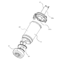
図2~図3により、おねば分離機構について詳述する。
おねば分離機構の内部には、例えばほぼ円筒状のケースからなるおねばを含む蒸気が通
過する流路23(以下、円筒状流路という)が設けられている。この円筒状流路23は、
おねば分離機構の内部に対しほぼ閉じられた空間部(内部空間)を形成し、おねばを含ん
だ蒸気の流入口22a(案内筒22の流出口)、流入口22aの反対側、すなわち下流側
に位置する蒸気排出口24、及びおねば排出口25が設けられており、流路ケースAを構
成している(図3参照)。なお、円筒状流路23は、その一部がおねば分離機構の内部空
間を構成する部材を共有するようにしてもよく、あるいは円筒状流路23の全部をおねば
分離機構の内部空間を構成する部材で形成するようにしてもよい。
おねば分離機構の内部には、例えばほぼ円筒状のケースからなるおねばを含む蒸気が通
過する流路23(以下、円筒状流路という)が設けられている。この円筒状流路23は、
おねば分離機構の内部に対しほぼ閉じられた空間部(内部空間)を形成し、おねばを含ん
だ蒸気の流入口22a(案内筒22の流出口)、流入口22aの反対側、すなわち下流側
に位置する蒸気排出口24、及びおねば排出口25が設けられており、流路ケースAを構
成している(図3参照)。なお、円筒状流路23は、その一部がおねば分離機構の内部空
間を構成する部材を共有するようにしてもよく、あるいは円筒状流路23の全部をおねば
分離機構の内部空間を構成する部材で形成するようにしてもよい。
円筒状流路23を形成する流路ケースAは、その断面積が流入口22a側から蒸気排出
口24側に向かって大きくなるようにしてあり、断面積が大きくなるに従って蒸気おねば
の速度が遅くなり、おねばが下側に落易いようになっている。
口24側に向かって大きくなるようにしてあり、断面積が大きくなるに従って蒸気おねば
の速度が遅くなり、おねばが下側に落易いようになっている。
円筒状流路23の内部には、おねばを含む蒸気の進行方向に対してほぼ直交する螺線状
の仕切り板(螺線状の翼)26が設けられており、螺線状の流路を形成している。そして
、蒸気とおねばの混合流体を旋回流によって蒸気とおねばに分離するようになっている。
なお、上記の螺線状の仕切り板26は、シリコンゴム等の弾性を持った材料で構成されて
いる。こうして、流入口22a側には、流路ケースAの上流側を塞ぎ下流側に螺線状の仕
切り板26が形成された螺線状の仕切部Bが嵌合されている(図3参照)。
なお、上記のような螺線状の仕切り板26に代えて、図4に示すように、円筒状流路2
3の流路方向の中心部に軸30を設けてもよい。この場合、軸30の断面形状は、流入口
22aから下流方向に向かって径が小さくなるほぼ円錐形の円筒軸とすることが望ましい
。
の仕切り板(螺線状の翼)26が設けられており、螺線状の流路を形成している。そして
、蒸気とおねばの混合流体を旋回流によって蒸気とおねばに分離するようになっている。
なお、上記の螺線状の仕切り板26は、シリコンゴム等の弾性を持った材料で構成されて
いる。こうして、流入口22a側には、流路ケースAの上流側を塞ぎ下流側に螺線状の仕
切り板26が形成された螺線状の仕切部Bが嵌合されている(図3参照)。
なお、上記のような螺線状の仕切り板26に代えて、図4に示すように、円筒状流路2
3の流路方向の中心部に軸30を設けてもよい。この場合、軸30の断面形状は、流入口
22aから下流方向に向かって径が小さくなるほぼ円錐形の円筒軸とすることが望ましい
。
円筒状流路23への流入口22a(案内筒22)は、円筒状流路23の流路ケースAの
円筒中心から一方の側にずらした位置、すなわち、流路ケースAの内壁のほぼ接線方向と
なる位置に設けてある。これによって、蒸気おねばを強制的に旋回させて、その遠心力に
よって蒸気とおねばを分離するようにしてある。
円筒中心から一方の側にずらした位置、すなわち、流路ケースAの内壁のほぼ接線方向と
なる位置に設けてある。これによって、蒸気おねばを強制的に旋回させて、その遠心力に
よって蒸気とおねばを分離するようにしてある。
円筒状流路23の出口側(下流側)のほぼ中心部には蒸気排出口24が設けられており
、また、円筒状流路23の下流側の下部外周側にはおねば排出口25が設けられている。
おねばを含む蒸気はその遠心力で旋回流をなし、おねばは円筒状流路23の径方向外側に
分離し、蒸気は円筒状流路23の中心部へと分離して、それぞれを蒸気排出口24、おね
ば排出口25から排出する。
なお、蒸気排出口24は円筒状流路23の出口側のほぼ中心部に設けてあるが、中心部
の径方向外側であっておねば排出口25の反対側にずらしてもよく、このようにすると、
蒸気の旋回が蒸気排出口24で遅くなるので蒸気が排出し易くなる。
また、おねば排出口25は旋回流の外側に設けておねばを分離するが、この場合、旋回
流の外側下部に設けたおねば排出口25部分のケース内の空間部の断面形状を排出口25
側に向かって大きくしてもよく、特に円筒状流路である場合は、円筒断面形状を排出口側
に向かって大きくして部分的なスクロール形状とすることができる。
、また、円筒状流路23の下流側の下部外周側にはおねば排出口25が設けられている。
おねばを含む蒸気はその遠心力で旋回流をなし、おねばは円筒状流路23の径方向外側に
分離し、蒸気は円筒状流路23の中心部へと分離して、それぞれを蒸気排出口24、おね
ば排出口25から排出する。
なお、蒸気排出口24は円筒状流路23の出口側のほぼ中心部に設けてあるが、中心部
の径方向外側であっておねば排出口25の反対側にずらしてもよく、このようにすると、
蒸気の旋回が蒸気排出口24で遅くなるので蒸気が排出し易くなる。
また、おねば排出口25は旋回流の外側に設けておねばを分離するが、この場合、旋回
流の外側下部に設けたおねば排出口25部分のケース内の空間部の断面形状を排出口25
側に向かって大きくしてもよく、特に円筒状流路である場合は、円筒断面形状を排出口側
に向かって大きくして部分的なスクロール形状とすることができる。
円筒状流路23の出口側に設けた蒸気排出口24は筒状に形成された蒸気流出筒24a
の入口部として構成されており、円筒状流路23から蒸気出口である蒸気孔27近傍まで
延設してある。こうすることによって、分離された蒸気が円筒状流路23の外部へ流出し
たおねばと再混合するのを防ぐことができる。なお、蒸気流出筒24aはその下流側で蒸
気孔27の近傍まで延設してあるが、蒸気孔27に直結させることもでき、このようにす
ると、外部へ流出したおねばと再混合するのを防ぐことができる。
また、蒸気排出口24、すなわち蒸気流出筒24aの上流側は、円筒状流路23の内側
(上流側)に筒状に延設されており、分離したおねばがここから流出しないための「返し
」的役割を果たしている。
こうして、円筒状流路23の出口側には、蒸気流出筒24aを備えた蒸気排出部Cが嵌
合されている(図3参照)。
上記の説明では、おねば分離機構を、図3に示すように、流路ケースA、螺線状の仕切
部B及び蒸気排出部Cの3部品を嵌合して構成した場合を示したが、螺線状の仕切り部B
と蒸気排出部Cとは一体に形成してもよい。
の入口部として構成されており、円筒状流路23から蒸気出口である蒸気孔27近傍まで
延設してある。こうすることによって、分離された蒸気が円筒状流路23の外部へ流出し
たおねばと再混合するのを防ぐことができる。なお、蒸気流出筒24aはその下流側で蒸
気孔27の近傍まで延設してあるが、蒸気孔27に直結させることもでき、このようにす
ると、外部へ流出したおねばと再混合するのを防ぐことができる。
また、蒸気排出口24、すなわち蒸気流出筒24aの上流側は、円筒状流路23の内側
(上流側)に筒状に延設されており、分離したおねばがここから流出しないための「返し
」的役割を果たしている。
こうして、円筒状流路23の出口側には、蒸気流出筒24aを備えた蒸気排出部Cが嵌
合されている(図3参照)。
上記の説明では、おねば分離機構を、図3に示すように、流路ケースA、螺線状の仕切
部B及び蒸気排出部Cの3部品を嵌合して構成した場合を示したが、螺線状の仕切り部B
と蒸気排出部Cとは一体に形成してもよい。
次に、上記のようなおねば分離機構を有する蒸気口ユニット20を備えた炊飯器の作用
を説明する。
水と米を入れた内釜2を炊飯器の本体1内に収容して蓋体10を閉じ、操作部に設けた
電源スイッチをONすると、電磁誘導コイル3の作用によって内釜2が加熱され、内釜2
内の水が沸騰すると、おねばを含んだ蒸気が発生する。このとき、内釜2の内圧が上昇し
ているため、蒸気口ユニット20の開閉弁28は、押し上げられておねば戻し孔28aを
閉塞しており、このため、おねばを含む蒸気は、案内筒22を通って、おねば分離機構の
円筒状流路23内に導かれる。
を説明する。
水と米を入れた内釜2を炊飯器の本体1内に収容して蓋体10を閉じ、操作部に設けた
電源スイッチをONすると、電磁誘導コイル3の作用によって内釜2が加熱され、内釜2
内の水が沸騰すると、おねばを含んだ蒸気が発生する。このとき、内釜2の内圧が上昇し
ているため、蒸気口ユニット20の開閉弁28は、押し上げられておねば戻し孔28aを
閉塞しており、このため、おねばを含む蒸気は、案内筒22を通って、おねば分離機構の
円筒状流路23内に導かれる。
案内筒22を出たおねばを含む蒸気は、円筒状流路23の内壁の接線方向から流路内部
に流入し、螺線状の仕切り板26に沿って螺線状の流路を強制的に旋回させられ、その遠
心力によって蒸気とおねばに分離される。そして、蒸気は、蒸気排出口24から蒸気流出
筒24aを通り、蒸気孔27から機外に放出される。一方、おねばは、おねば排出口25
から排出され、溜り凹部21に溜められる。
に流入し、螺線状の仕切り板26に沿って螺線状の流路を強制的に旋回させられ、その遠
心力によって蒸気とおねばに分離される。そして、蒸気は、蒸気排出口24から蒸気流出
筒24aを通り、蒸気孔27から機外に放出される。一方、おねばは、おねば排出口25
から排出され、溜り凹部21に溜められる。
その後、加熱が停止して、内釜2の内圧が低下すると、開閉弁28は、自重およびおね
ばの重量によって下降し、溜り凹部21の底面に設けられたおねば戻し穴28aを開口す
る。これにより、溜り凹部21内に溜まったおねばは、おねば戻し穴28aから内釜2内
に落下する。おねばが内釜2内のご飯に戻ることにより、おねばに含まれるおいしさの成
分がご飯に与えられて、つやや粘りのあるおいしいご飯を炊くことができる。
ばの重量によって下降し、溜り凹部21の底面に設けられたおねば戻し穴28aを開口す
る。これにより、溜り凹部21内に溜まったおねばは、おねば戻し穴28aから内釜2内
に落下する。おねばが内釜2内のご飯に戻ることにより、おねばに含まれるおいしさの成
分がご飯に与えられて、つやや粘りのあるおいしいご飯を炊くことができる。
本発明に係る炊飯器の蒸気口ユニット20は、流入口22aから流入したおねばを含む
蒸気を通す流路23を有し、流路23内部のおねばを含む蒸気の進行方向に、遠心力でお
ねばを流路23の径方向に分離し、蒸気を流路23の進行方向に分離する分離機構を備え
たので、加熱手段30への入力電力が大きくその継続時間が長くても、確実に蒸気とおね
ばを分離することができ、しかも小型化が可能で、設計的、デザイン的制約も少ない。
蒸気を通す流路23を有し、流路23内部のおねばを含む蒸気の進行方向に、遠心力でお
ねばを流路23の径方向に分離し、蒸気を流路23の進行方向に分離する分離機構を備え
たので、加熱手段30への入力電力が大きくその継続時間が長くても、確実に蒸気とおね
ばを分離することができ、しかも小型化が可能で、設計的、デザイン的制約も少ない。
1 炊飯器本体、2 内釜、3 電磁誘導コイル(加熱手段)、10 蓋体、20 蒸
気口ユニット、22 案内筒、22a 流入口、23 円筒状流路(流路)、24 蒸気
排出口、24a 蒸気流出筒、25 おねば排出口、26 螺旋状の仕切り板、27 蒸
気孔(蒸気を機外に排出する出口)、30 円筒状の軸、A 流路ケース、B 螺線状の仕切部、C 蒸気排出部。
気口ユニット、22 案内筒、22a 流入口、23 円筒状流路(流路)、24 蒸気
排出口、24a 蒸気流出筒、25 おねば排出口、26 螺旋状の仕切り板、27 蒸
気孔(蒸気を機外に排出する出口)、30 円筒状の軸、A 流路ケース、B 螺線状の仕切部、C 蒸気排出部。
Claims (17)
- 炊飯器本体と、該炊飯器本体の上部開口部を覆う蓋体と、前記炊飯器本体内に着脱可能
に収容される内釜と、該内釜を加熱する加熱手段と、前記蓋体に設けられ、炊飯中に発生
した蒸気を前記内釜から炊飯器本体の外部に排出する蒸気口ユニットとを有し、
前記蒸気口ユニットは、内部に流入口から流入したおねばを含む蒸気を通す流路が設け
られ、該流路内部のおねばを含む蒸気の進行方向に、遠心力によりおねばを流路の径方向
に分離すると共に蒸気を流路の進行方向に分離して、前記おねばをおねば排出口から排出
し、前記蒸気を蒸気排出口から排出する分離機構を備えたことを特徴とする炊飯器。 - 前記おねばを含む蒸気を分離する流路がほぼ閉じられた空間部を形成することを特徴と
する請求項1記載の炊飯器。 - 前記閉じられた空間がほぼ円筒状の空間であることを特徴とする請求項2記載の炊飯器
。 - 前記閉じられた空間の断面積が、前記流入口から蒸気排出口側に向かって大きくなるこ
とを特徴とする請求項1~3のいずれかに記載の炊飯器。 - 前記分離機構は、前記流路内部のおねばを含む蒸気の進行方向とほぼ直交して配置され
、蒸気とおねばを遠心力によって分離する螺旋状の仕切り板を備えたことを特徴とする請
求項1~4のいずれかに記載の炊飯器。 - 前記螺線状の仕切り板が弾性材料からなることを特徴とする請求項5記載の炊飯器。
- 前記分離機構は、前記流路内部のおねばを含む蒸気の進行方向に、蒸気とおねばを遠心
力によって分離するほぼ円筒状の軸を備えたことを特徴とする請求項1~4のいずれかに
記載の炊飯器。 - 前記ほぼ円筒状の軸は、前記流路内部のおねばを含む蒸気の進行方向に向かって縮径す
ることを特徴とする請求項7記載の炊飯器。 - 前記流路内へのおねばを含む蒸気の流入位置を、前記流路の内壁のほぼ接線方向とした
ことを特徴とする請求項1~8のいずれかに記載の炊飯器。 - 前記流路の径方向におねば排出口を設けたことを特徴とする請求項1~9のいずれかに
記載の炊飯器。 - 前記流路の径方向の旋回流の外側下部におねば排出口を設けたことを特徴とする請求項
10記載の炊飯器。 - 前記旋回流の外側下部に設けたおねば排出口部分のケース内空間部の断面形状を排出口
側に向かって大きくしたことを特徴とする請求項11記載の炊飯器。 - 前記蒸気排出口を前記流路の径方向のほぼ中心部に設けたことを特徴とする請求項1~
12のいずれかに記載の炊飯器。 - 前記蒸気排出口を前記流路の径方向の中心部から一方の側にずらしたことを特徴とする
請求項1~12のいずれかに記載の炊飯器。 - 前記流路の下流側に蒸気排出口を設け、該蒸気排出口を蒸気を機外に排出する出口近傍
まで延設したことを特徴とする請求項1~14のいずれかに記載の炊飯器。 - 前記蒸気排出口を前記流路側に筒状に延設したことを特徴とする請求項15記載の炊飯
器。 - おねばを含む蒸気を分離する流路をほぼ水平に配設したことを特徴とする請求項1~1
6のいずれかに記載の炊飯器。
Priority Applications (2)
| Application Number | Priority Date | Filing Date | Title |
|---|---|---|---|
| HK13102173.0A HK1174807B (en) | 2010-02-17 | 2011-01-12 | Rice cooker |
| CN201180009918.7A CN102762134B (zh) | 2010-02-17 | 2011-01-12 | 电饭锅 |
Applications Claiming Priority (2)
| Application Number | Priority Date | Filing Date | Title |
|---|---|---|---|
| JP2010032730A JP5495840B2 (ja) | 2010-02-17 | 2010-02-17 | 炊飯器 |
| JP2010-032730 | 2010-02-17 |
Publications (1)
| Publication Number | Publication Date |
|---|---|
| WO2011102071A1 true WO2011102071A1 (ja) | 2011-08-25 |
Family
ID=44482680
Family Applications (1)
| Application Number | Title | Priority Date | Filing Date |
|---|---|---|---|
| PCT/JP2011/000092 Ceased WO2011102071A1 (ja) | 2010-02-17 | 2011-01-12 | 炊飯器 |
Country Status (4)
| Country | Link |
|---|---|
| JP (1) | JP5495840B2 (ja) |
| CN (1) | CN102762134B (ja) |
| TW (1) | TWI429413B (ja) |
| WO (1) | WO2011102071A1 (ja) |
Cited By (2)
| Publication number | Priority date | Publication date | Assignee | Title |
|---|---|---|---|---|
| CN104622267A (zh) * | 2015-02-13 | 2015-05-20 | 彭枫 | 粒米饭和米汤全自动分离电饭锅 |
| CN107174121A (zh) * | 2015-10-16 | 2017-09-19 | 胡振强 | 电饭煲的防溢方法 |
Families Citing this family (4)
| Publication number | Priority date | Publication date | Assignee | Title |
|---|---|---|---|---|
| CN105078213A (zh) * | 2015-09-11 | 2015-11-25 | 王�忠 | 一种米饭的加工方法以及加工米饭的锅具 |
| CN108135383B (zh) * | 2015-10-30 | 2020-08-07 | 三菱电机株式会社 | 电饭锅 |
| JP6566894B2 (ja) * | 2016-03-01 | 2019-08-28 | 三菱電機株式会社 | 炊飯器 |
| CN115670250A (zh) * | 2021-07-30 | 2023-02-03 | 上海爱餐机器人(集团)有限公司 | 一种用于炒菜机中的下料机构 |
Citations (2)
| Publication number | Priority date | Publication date | Assignee | Title |
|---|---|---|---|---|
| JP2006061211A (ja) * | 2004-08-24 | 2006-03-09 | Mitsubishi Electric Corp | 蒸気分離容器およびそれを用いた炊飯器 |
| JP2007135730A (ja) * | 2005-11-16 | 2007-06-07 | Matsushita Electric Ind Co Ltd | 炊飯器 |
Family Cites Families (3)
| Publication number | Priority date | Publication date | Assignee | Title |
|---|---|---|---|---|
| JP3923388B2 (ja) * | 2002-07-31 | 2007-05-30 | 象印マホービン株式会社 | 炊飯器等の蒸気低温化構造 |
| JP3858832B2 (ja) * | 2003-02-20 | 2006-12-20 | 松下電器産業株式会社 | 炊飯器 |
| JP5424925B2 (ja) * | 2010-02-12 | 2014-02-26 | 三菱電機株式会社 | 炊飯器 |
-
2010
- 2010-02-17 JP JP2010032730A patent/JP5495840B2/ja not_active Expired - Fee Related
-
2011
- 2011-01-12 WO PCT/JP2011/000092 patent/WO2011102071A1/ja not_active Ceased
- 2011-01-12 CN CN201180009918.7A patent/CN102762134B/zh not_active Expired - Fee Related
- 2011-01-17 TW TW100101595A patent/TWI429413B/zh not_active IP Right Cessation
Patent Citations (2)
| Publication number | Priority date | Publication date | Assignee | Title |
|---|---|---|---|---|
| JP2006061211A (ja) * | 2004-08-24 | 2006-03-09 | Mitsubishi Electric Corp | 蒸気分離容器およびそれを用いた炊飯器 |
| JP2007135730A (ja) * | 2005-11-16 | 2007-06-07 | Matsushita Electric Ind Co Ltd | 炊飯器 |
Cited By (3)
| Publication number | Priority date | Publication date | Assignee | Title |
|---|---|---|---|---|
| CN104622267A (zh) * | 2015-02-13 | 2015-05-20 | 彭枫 | 粒米饭和米汤全自动分离电饭锅 |
| CN107174121A (zh) * | 2015-10-16 | 2017-09-19 | 胡振强 | 电饭煲的防溢方法 |
| CN107174121B (zh) * | 2015-10-16 | 2019-09-13 | 温州启真信息技术有限公司 | 电饭煲的防溢方法 |
Also Published As
| Publication number | Publication date |
|---|---|
| TW201143688A (en) | 2011-12-16 |
| TWI429413B (zh) | 2014-03-11 |
| CN102762134B (zh) | 2015-07-15 |
| HK1174807A1 (zh) | 2013-06-21 |
| JP5495840B2 (ja) | 2014-05-21 |
| JP2011167303A (ja) | 2011-09-01 |
| CN102762134A (zh) | 2012-10-31 |
Similar Documents
| Publication | Publication Date | Title |
|---|---|---|
| JP5495840B2 (ja) | 炊飯器 | |
| KR101920985B1 (ko) | 음료의 준비를 위한 카트리지 | |
| RU2676572C2 (ru) | Устройство для разлива напитка | |
| CA2801995C (en) | A cartridge containing one or more beverage ingredients and a method of making a beverage using such a cartridge | |
| JP2013240504A (ja) | 電気炊飯器 | |
| JP5424925B2 (ja) | 炊飯器 | |
| CN208784381U (zh) | 盖体及烹饪器具 | |
| CN205885250U (zh) | 蒸汽阀和烹饪器具 | |
| JP5484212B2 (ja) | 炊飯器 | |
| JP5709687B2 (ja) | 炊飯器 | |
| CN208784448U (zh) | 破泡器、盖体及烹饪器具 | |
| JP5538088B2 (ja) | 炊飯器 | |
| JP6566894B2 (ja) | 炊飯器 | |
| HK1174807B (en) | Rice cooker | |
| TWI629033B (zh) | 漩茶機 | |
| CN208784447U (zh) | 破泡器、盖体及烹饪器具 | |
| JP2006061211A (ja) | 蒸気分離容器およびそれを用いた炊飯器 | |
| JP2013059365A (ja) | 鍋 | |
| JP2012010874A (ja) | 圧力式炊飯器 | |
| JP2013034657A (ja) | 炊飯器 | |
| CN208481125U (zh) | 蒸汽阀及具有其的食物加热装置 | |
| JP6460441B2 (ja) | 炊飯器 | |
| CN220453630U (zh) | 一种带旋风分离器的锅炉 | |
| CN107440538A (zh) | 蒸汽阀和烹饪器具 | |
| KR20230065796A (ko) | 자동전기압력밥솥의 쌀 투입 구조 |
Legal Events
| Date | Code | Title | Description |
|---|---|---|---|
| WWE | Wipo information: entry into national phase |
Ref document number: 201180009918.7 Country of ref document: CN |
|
| 121 | Ep: the epo has been informed by wipo that ep was designated in this application |
Ref document number: 11744366 Country of ref document: EP Kind code of ref document: A1 |
|
| NENP | Non-entry into the national phase |
Ref country code: DE |
|
| 122 | Ep: pct application non-entry in european phase |
Ref document number: 11744366 Country of ref document: EP Kind code of ref document: A1 |