WO2011096451A1 - ヒューズユニット - Google Patents
ヒューズユニット Download PDFInfo
- Publication number
- WO2011096451A1 WO2011096451A1 PCT/JP2011/052179 JP2011052179W WO2011096451A1 WO 2011096451 A1 WO2011096451 A1 WO 2011096451A1 JP 2011052179 W JP2011052179 W JP 2011052179W WO 2011096451 A1 WO2011096451 A1 WO 2011096451A1
- Authority
- WO
- WIPO (PCT)
- Prior art keywords
- bolt
- fuse element
- fuse
- terminal connection
- terminal
- Prior art date
- Legal status (The legal status is an assumption and is not a legal conclusion. Google has not performed a legal analysis and makes no representation as to the accuracy of the status listed.)
- Ceased
Links
Images







Classifications
-
- H—ELECTRICITY
- H01—ELECTRIC ELEMENTS
- H01H—ELECTRIC SWITCHES; RELAYS; SELECTORS; EMERGENCY PROTECTIVE DEVICES
- H01H85/00—Protective devices in which the current flows through a part of fusible material and this current is interrupted by displacement of the fusible material when this current becomes excessive
- H01H85/02—Details
- H01H85/04—Fuses, i.e. expendable parts of the protective device, e.g. cartridges
- H01H85/041—Fuses, i.e. expendable parts of the protective device, e.g. cartridges characterised by the type
- H01H85/044—General constructions or structure of low voltage fuses, i.e. below 1000 V, or of fuses where the applicable voltage is not specified
-
- H—ELECTRICITY
- H01—ELECTRIC ELEMENTS
- H01H—ELECTRIC SWITCHES; RELAYS; SELECTORS; EMERGENCY PROTECTIVE DEVICES
- H01H85/00—Protective devices in which the current flows through a part of fusible material and this current is interrupted by displacement of the fusible material when this current becomes excessive
- H01H85/02—Details
- H01H85/04—Fuses, i.e. expendable parts of the protective device, e.g. cartridges
- H01H85/05—Component parts thereof
- H01H85/055—Fusible members
- H01H85/12—Two or more separate fusible members in parallel
-
- H—ELECTRICITY
- H01—ELECTRIC ELEMENTS
- H01H—ELECTRIC SWITCHES; RELAYS; SELECTORS; EMERGENCY PROTECTIVE DEVICES
- H01H85/00—Protective devices in which the current flows through a part of fusible material and this current is interrupted by displacement of the fusible material when this current becomes excessive
- H01H85/02—Details
- H01H85/04—Fuses, i.e. expendable parts of the protective device, e.g. cartridges
- H01H85/05—Component parts thereof
- H01H85/143—Electrical contacts; Fastening fusible members to such contacts
-
- H—ELECTRICITY
- H01—ELECTRIC ELEMENTS
- H01H—ELECTRIC SWITCHES; RELAYS; SELECTORS; EMERGENCY PROTECTIVE DEVICES
- H01H85/00—Protective devices in which the current flows through a part of fusible material and this current is interrupted by displacement of the fusible material when this current becomes excessive
- H01H85/02—Details
- H01H85/0241—Structural association of a fuse and another component or apparatus
- H01H2085/025—Structural association with a binding post of a storage battery
-
- H—ELECTRICITY
- H01—ELECTRIC ELEMENTS
- H01H—ELECTRIC SWITCHES; RELAYS; SELECTORS; EMERGENCY PROTECTIVE DEVICES
- H01H85/00—Protective devices in which the current flows through a part of fusible material and this current is interrupted by displacement of the fusible material when this current becomes excessive
- H01H85/02—Details
- H01H85/04—Fuses, i.e. expendable parts of the protective device, e.g. cartridges
- H01H85/05—Component parts thereof
- H01H85/055—Fusible members
- H01H2085/0555—Input terminal connected to a plurality of output terminals, e.g. multielectrode
-
- H—ELECTRICITY
- H01—ELECTRIC ELEMENTS
- H01H—ELECTRIC SWITCHES; RELAYS; SELECTORS; EMERGENCY PROTECTIVE DEVICES
- H01H85/00—Protective devices in which the current flows through a part of fusible material and this current is interrupted by displacement of the fusible material when this current becomes excessive
- H01H85/02—Details
- H01H85/20—Bases for supporting the fuse; Separate parts thereof
- H01H85/2045—Mounting means or insulating parts of the base, e.g. covers, casings
Definitions
- the present invention relates to a fuse unit in which a bolt is fixed to a terminal connection portion and the terminal is fixed using the bolt.
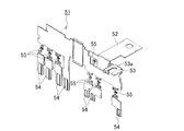
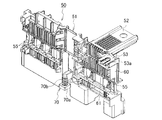
- the fuse unit 50 includes a fuse element 51 formed of a conductive metal plate, and an insulating resin portion 60 formed by insert molding using the fuse element 51 as an insert part.
- the fuse element 51 includes a first power supply connection portion 52 that is fixed to a battery post (not shown) via a battery connection terminal (not shown), and a bolt 70.
- the soluble part 55 is formed.
- a U-shaped bolt insertion hole 53 a is formed in the first terminal connection portion 53 of the fuse element 51. As shown in detail in FIG. 14, a press-fitting space 61 is formed by the insulating resin portion 20 on the back surface side of the bolt insertion hole 53 a.
- the bolt 70 in which the rod portion 70b is inserted into the bolt insertion hole 53a is fixed by press-fitting its head portion 70a into the press-fitting space 61 (see FIG. 12).
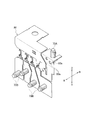
- a pin entry port 80 a into which a mold pressing pin (not shown) can enter is formed in the fuse element 80, and a pressing pin (not shown) is formed together with the fuse element 80.
- the insulating resin portion (not shown) is formed by insert molding using the bolt 70A positioned in step 1) as an insert part.
- the inserted bolt 70A is fixed by an insulating resin filled in the surroundings.
- the direction of the bolt 70A that can be positioned by a pressing pin (not shown) of the mold is limited.
- the bolt 70A that moves in the vertical direction is positioned, the bolt 70B that moves in the left-right direction cannot be positioned on the mold side.
- the mold structure becomes complicated.
- the present invention has been made to solve the above-described problems, and the manufacturing process is easy, and the design freedom of the fuse element is not limited by the installation direction of the bolt, and the mold structure is complicated.
- An object is to provide a fuse unit that does not.
- 1st invention is a fuse unit provided with the fuse element in which the connection part for terminals was formed, and the insulating resin part arrange
- the second invention is the fuse unit according to the first invention, wherein the bolt temporary fixing means is a bolt screw hole provided in the terminal connecting portion.
- 3rd invention is a fuse unit of 1st invention, Comprising:
- the said bolt temporary fixing means is provided in the said terminal connection part,
- the bolt hole which has an open port in the end surface of the said fuse element,
- the said bolt hole And a bolt holding part for holding the head of the bolt inserted into the slide.
- a fourth invention is a fuse unit according to the third invention, wherein the bolt holding portion is formed by bending the fuse element.
- the bolt can be temporarily fixed to the fuse element, the insulating resin portion can be formed by insert molding using both the fuse element and the bolt as insert parts. Therefore, it is not necessary to perform bolt press-fitting after insert molding. Further, since the bolt can be temporarily fixed by the fuse element itself, the bolt can be temporarily fixed regardless of the direction of the bolt. As described above, the manufacturing process is easy, and the degree of freedom in designing the fuse element is not limited by the installation direction of the bolt, and the mold structure is not complicated.
- the bolt in addition to the effects of the first invention, the bolt can be temporarily fixed simply by screwing the bolt into the bolt screw hole, so that temporary fixing is easy.
- the bolt in addition to the effects of the first invention, the bolt can be temporarily fixed simply by slidingly inserting the bolt into the bolt hole, so that temporary fixing is easy.
- the bolt holding portion can be formed by bending the fuse element, it can be easily produced without adding a manufacturing process or parts.
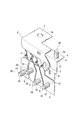
- FIG. 1A is a perspective view of a fuse unit
- FIG. 1B is an enlarged sectional view taken along line AA of FIG. 1A, showing a first embodiment of the present invention. It is a perspective view of the fuse element which showed 1st Embodiment of this invention and the bolt was temporarily fixed. It is a back view of the fuse element which showed 1st Embodiment of this invention and the volt
- FIG. 4A shows a second embodiment of the present invention
- FIG. 4A is a perspective view of the fuse unit
- FIG. 4B is a sectional view taken along line BB of FIG. 4A.
- FIG. 6 is a perspective view showing a second embodiment of the present invention before the fuse element is bent.
- FIG. 6A shows a second embodiment of the present invention
- FIG. 6A is a perspective view of a fuse element
- FIG. 6B is a front view of a connection portion for a first terminal of the fuse element
- FIG. It is a bottom view of the connection part for 1st terminals.
- FIG. 7A shows a second embodiment of the present invention
- FIG. 7A is a perspective view showing a process of temporarily fixing a bolt to the first terminal connection portion of the fuse element
- FIG. 7B is for the first terminal of the fuse element. It is a perspective view which shows the state which fixed the volt
- FIG. 8A shows a second embodiment of the present invention
- FIG. 8A is a plan view of a first terminal connection portion to which a bolt is temporarily fixed
- FIG. 8B is a first terminal connection portion to which a bolt is temporarily fixed.
- FIG. 9 (a) is a perspective view of a volt
- FIG.9 (b) is a front view of a volt
- FIG. 9 is a perspective view of a main part of a first terminal connection portion of a fuse element according to a third embodiment of the present invention. It is a perspective view of a fuse unit, showing a first conventional example.
- FIG. 12 is a cross-sectional view taken along the line CC of FIG. 11 showing a first conventional example.
- FIG. 3 is a perspective view of a fuse element showing a first conventional example. It is a perspective view which shows a 1st prior art example and shows the press injection process of a volt
- FIG. 7 is a perspective view of a fuse element and a bolt temporarily fixed thereto, showing a second conventional example.
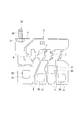
- FIG. 1 (a) to 3 show a first embodiment of the present invention
- FIG. 1 (a) is a perspective view of a fuse unit 1A
- FIG. 1 (b) is an enlarged cross-sectional view taken along line AA of FIG. 1 (a).
- 2 is a perspective view of the fuse element 2 to which the bolt 30 is temporarily fixed
- FIG. 3 is a rear view of the fuse element 2 to which the bolt 30 is temporarily fixed.
- the fuse unit 1A includes a fuse element 2 formed of a conductive metal plate (bus bar), and an insulating resin portion 20 disposed on the outer surface of the fuse element 2. .
- the fuse element 2 includes a power supply connection portion 3 fixed to a battery post (not shown) via a battery connection terminal (not shown), and a bolt 30.
- the first terminal connection portion 4, the four second terminal connection portions 5, the power supply connection portion 3, the first fusible portion 6 disposed between the first terminal connection portions 4, and the power supply Four second soluble portions 7 arranged between the connection portion 3 and each second terminal connection portion 5 are formed.
- a bolt insertion hole 3 a is formed in the power feeding connection portion 3.
- a battery connection terminal (not shown) is fixed using the bolt insertion hole 3a.
- the first terminal connecting portion 4 and each second terminal connecting portion 5 are respectively formed with bolt screw holes 10 which are temporary bolt fixing means. That is, a thread groove (in particular, no reference numeral) is formed on the inner surface of each bolt screw hole 10.
- Bolts 30 are screwed into the respective bolt screw holes 10.
- the bolt 30 includes a head portion 31 and a rod portion 32 having a thread groove formed on the outer periphery. The bolt 30 can be temporarily fixed by the fuse element 2 alone by being screwed into the bolt screw hole 10.
- the insulating resin part 20 is formed by insert molding using both the fuse element 2 and the bolt 30 temporarily fixed thereto as an insert part.
- the insulating resin portion 20 basically covers portions other than the power supply connection portion 3, the first terminal connection portion 4, the second terminal connection portion 5, the first soluble portion 6, and the second soluble portion 7. Yes. Further, as shown in detail in FIG. 1B, the insulating resin portion 20 is also disposed around the head portion 31 of each bolt 30 without a gap. The head portion 31 of each bolt 30 is fixed so as not to be rotated by the insulating resin portion 20.
- the terminal (not shown) inserted into the bolt 30 is fixed to the first terminal connecting part 4 and each second terminal connecting part 5 by fastening with a nut (not shown).
- a fuse element 2 having a desired form is manufactured by punching and bending a conductive metal plate material.
- screw holes are formed in the holes of the first terminal connecting portion 4 and the second terminal connecting portion 5 to form bolt screw holes 10.
- each bolt 30 is temporarily fixed to the fuse element 2.
- the fuse element 2 to which the bolt 30 is temporarily fixed is insert-molded as an insert part, and the insulating resin portion 20 is formed on the outer surface of the fuse element 2. From the above, the manufacture of the fuse unit 1A shown in FIGS. 1A and 1B is completed.
- the bolt screw hole 10 serving as a temporary bolt fixing means is provided in the first terminal connection portion 4 and the second terminal connection portion 5 of the fuse element 2, the bolt 30 is provided in the fuse element 2. Therefore, the insulating resin portion 20 can be formed by insert molding using both the fuse element 2 and the bolt 30 as insert parts as described above. Therefore, it is not necessary to perform bolt press-fitting after insert molding. Moreover, since the bolt 30 can be temporarily fixed by the fuse element 2 alone, the bolt 30 can be temporarily fixed regardless of the direction of the bolt 30. As described above, the manufacturing process is easy, and the design freedom of the fuse element 2 is not limited by the installation direction of the bolts 30, and the mold structure is not complicated.
- the bolt 30 is fixed to the fuse element 2 by a screw fastening force and is fixed to the insulating resin portion 20 by the holding force of the insulating resin filled in the periphery, the fixing strength of the bolt 30 is higher than that of the conventional example. Will improve.
- the bolt temporary fixing means is the bolt screw hole 10 provided in the first terminal connection portion 4 and the second terminal connection portion 5, the bolt 30 can be simply screwed into the bolt screw hole 10. Can be temporarily fixed, so that temporary fixing is easy.
- FIG. 4 (a) is a perspective view of the fuse unit 1B
- FIG. 4 (b) is a cross-sectional view taken along line BB in FIG. 4 (a).
- FIG. 5 is a perspective view of the fuse element 2 before bending
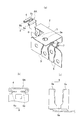
- FIG. 6 (a) is a perspective view of the fuse element 2
- FIG. 6 (b) is a front view of the first terminal connecting portion 4 of the fuse element 2.
- FIG. 6 (c) is a bottom view of the first terminal connecting portion 4 of the fuse element 2
- FIG. 7 (a) shows a process of temporarily fixing the bolt 30A to the first terminal connecting portion 4 of the fuse element 2.
- FIG. 4 (a) is a perspective view of the fuse unit 1B
- FIG. 4 (b) is a cross-sectional view taken along line BB in FIG. 4 (a).
- FIG. 5 is a perspective view of the fuse element 2 before bending
- FIG. 6 (a) is a perspective view of the fuse element 2
- FIG. 6 (b) is
- FIG. 7B is a perspective view showing a state in which the bolt 30A is temporarily fixed to the first terminal connecting portion 4 of the fuse element 2
- FIG. 8A is a view for the first terminal in which the bolt 30A is temporarily fixed.
- FIG. 8B is a plan view of the connecting portion 4, and the first terminal connecting portion 4 to which the bolt 30 ⁇ / b> A is temporarily fixed.
- Bottom view, FIG. 9 (a) perspective of the bolt 30A, and FIG. 9 (b) is a front view of the bolt 30A.
- the fuse unit 1B includes a fuse element 2 formed of a conductive metal plate (bus bar), and an insulating resin portion disposed on the outer surface of the fuse element 2. 20.
- the fuse element 2 includes a power supply connection portion 3 fixed to a battery post (not shown) via a battery connection terminal (not shown), and a bolt 30A.
- the first terminal connection portion 4, the four second terminal connection portions 5, the power supply connection portion 3, the first fusible portion 6 disposed between the first terminal connection portions 4, and the power supply Four second soluble portions 7 arranged between the connection portion 3 and each second terminal connection portion 5 are formed.
- a bolt insertion hole 3 a is formed in the power feeding connection portion 3.
- a battery connection terminal (not shown) is fixed using the bolt insertion hole 3a.
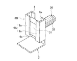
- a bolt temporary fixing means 8A is formed in the first terminal connecting portion 4.
- the bolt temporary fixing means 8A is provided in the first terminal connecting portion 4 and has a bolt hole 8a having an open port on the end face of the fuse element 2 and a bolt holding portion 9 for holding the bolt 30A slidably inserted into the bolt hole 8a.
- the bolt hole 8a is a U-shaped groove when viewed from above.
- the bolt holding portion 9 is formed by bending a pair of sandwiching pieces 9 a extending from both side ends of the first terminal connecting portion 4 in directions facing each other. Between the end surfaces of the pair of sandwiching pieces 9a facing each other, a narrow portion is formed in the middle of the entrance side and the innermost position.
- the width dimension between the end faces at the innermost position is the same as the inner surface width of the annular groove 31a of the head 31 of the bolt 30A, and the width dimension between the end faces at the narrow position is the annular groove 31a of the head 31 of the bolt 30A. It is set slightly narrower than the inner surface width.
- a bolt 30A is slid into the bolt hole 8a of the first terminal connection portion 4 and the pair of clamping pieces 9a.
- the slide-inserted bolt 30A has its rod portion 32 inserted into the bolt hole 8a and a pair of clamping pieces in the annular groove 31a of the head portion 31. 9a has entered. That is, the bolt 30A is temporarily fixed by the pair of clamping pieces 9a engaging with the annular groove 31a of the head portion 31 of the bolt 30A.
- the bolt 30A includes a head portion 31 and a rod portion 32 in which an outer peripheral thread groove is formed.
- An annular groove 31 a is formed on the side surface of the head portion 31.
- the insulating resin portion 20 is formed by insert molding using both the fuse element 2 and the bolt 30A temporarily fixed thereto as insert parts.
- the insulating resin portion 20 basically covers portions other than the power supply connection portion 3, the first terminal connection portion 4, the second terminal connection portion 5, the first soluble portion 6, and the second soluble portion 7. Yes. Further, as shown in detail in FIG. 4B, the insulating resin portion 20 is also disposed around the head portion 31 of the bolt 30A without any gap. The head portion 31 of the bolt 30 ⁇ / b> A is fixed by the insulating resin portion 20 so as not to rotate.
- a terminal (not shown) inserted into the bolt 30A is fixed to the first terminal connecting portion 4 by fastening with a nut (not shown).
- a method for manufacturing the fuse unit 1B having the above configuration will be briefly described.
- a conductive metal plate material is punched to produce a flat fuse element 2.
- the fuse element 2 having a desired form is manufactured by bending the same. At the time of this bending process, the pair of sandwiching pieces 9a are also bent.
- the bolt 30A is slid and inserted between the bolt hole 8a of the first terminal connecting portion 4 and the pair of holding pieces 9a.
- the bolt 30A is temporarily fixed to the fuse element 2 as shown in FIGS. 7 (b) and 8 (a) to 8 (b).
- the fuse element 2 to which the bolt 30A is temporarily fixed is insert-molded as an insert part, and the insulating resin portion 20 is formed on the outer surface of the fuse element 2. From the above, the manufacture of the fuse unit 1B shown in FIGS. 4A and 4B is completed.
- the bolt terminal 8 of the fuse terminal 2 is provided with the bolt hole 8a as the temporary bolt fixing means 8A and the bolt holding portion 9, so that the bolt 30A can be temporarily fixed to the fuse element 2. Therefore, the insulating resin portion 20 can be formed by insert molding using both the fuse element 2 and the bolt 30A as insert parts. Therefore, it is not necessary to perform bolt press-fitting after insert molding. Further, since the bolt 30A can be temporarily fixed with the fuse element 2 alone, the bolt 30A can be temporarily fixed regardless of the direction of the bolt 30A. From the above, the manufacturing process is easy, and the design freedom of the fuse element 2 is not limited by the installation direction of the bolt 30A, and the mold structure is not complicated.
- the bolt 30A is fixed to the fuse element 2 by the holding force of the bolt holding portion 9 and is fixed to the insulating resin portion 20 by the holding force of the insulating resin filled in the surroundings.
- the fixing strength of 30A is improved.
- the bolt temporary fixing means 8A is provided in the first terminal connecting portion 4, and holds a bolt hole 8a having an open port on the end face of the fuse element 2, and a head 31 of the bolt 30A slidably inserted into the bolt hole 8a. Since the bolt holding part 9 is provided, the bolt 30A can be temporarily fixed simply by slidingly inserting the bolt 30A between the bolt hole 8a and the pair of sandwiching pieces 9a, so that temporary fixing is easy.
- the bolt holding part 9 is formed by bending a pair of clamping pieces 9a extending from the fuse element 2, the bolt holding part 9 can be formed by bending the fuse element 2, so that a manufacturing process and parts are added. It can be easily manufactured without doing.
- the bolt temporary fixing means 8A is provided in the first terminal connecting portion 4, but the bolt temporary fixing means 8A may be provided in each second terminal connecting portion 5 as well.
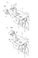
- FIG. 10 is a perspective view of a main part of the first terminal connecting portion 4 of the fuse element 2 according to the third embodiment of the present invention.
- the first terminal connection portion 4 of the fuse element 2 is provided with a bolt temporary fixing means 8B as in the second embodiment.
- the bolt temporary fixing means 8B is provided in the first terminal connecting portion 4, and is a bolt holding unit that holds a bolt hole 8a having an open port on the end face of the fuse element 2 and a bolt 30 that is slid into the bolt hole 8a. 9A, but the configuration of the bolt holding portion 9A is different.
- the bolt holding portion 9A is formed by bending a pair of press-fitting pieces 9b extending from both side ends of the first terminal connection portion 4 in a direction facing each other at a predetermined width dimension.
- the width dimension between the first terminal connecting portion 4 and each press-fitting piece 9 b is set to be slightly larger than the height dimension of the head portion 31 of the bolt 30.
- each press-fitting piece 9b is provided with a stopper portion 9c for preventing excessive entry of the bolt 30.
- a bolt 30 is slid and inserted into the internal space of the bolt hole 8a and the pair of press-fitting pieces 9b of the first terminal connecting portion 4.
- the slide-inserted bolt 30 has its rod portion 32 inserted into the bolt hole 8a, and its head portion 31 is press-fitted into the pair of press-fitting pieces 9b. That is, the bolt 30 is temporarily fixed to the fuse element 2 by press fitting.
- the bolt 30 is composed of a head portion 31 and a rod portion 32 having a thread groove formed on the outer periphery.
- a fuse unit (not shown) can be manufactured by the same manufacturing procedure as in the second embodiment.
- the bolt terminal 8 of the fuse element 2 and the bolt hole 8a as the bolt temporary fixing means 8B and the bolt holding portion 9A are provided, so that the bolt 30 can be temporarily fixed to the fuse element 2. Therefore, an insulating resin portion (not shown) can be formed by insert molding using both the fuse element 2 and the bolt 30 as insert parts. Therefore, it is not necessary to perform bolt press-fitting after insert molding. Moreover, since the bolt 30 can be temporarily fixed by the fuse element 2 alone, the bolt 30 can be temporarily fixed regardless of the direction of the bolt 30. As described above, the manufacturing process is easy, and the design freedom of the fuse element 2 is not limited by the installation direction of the bolts 30, and the mold structure is not complicated.
- the bolt 30 is fixed to the fuse element 2 by the holding force of the bolt holding portion 9A and is fixed to the insulating resin portion (not shown) by the holding force of the insulating resin filled in the surroundings. In comparison, the fixing strength of the bolt 30 is improved.
- the bolt temporary fixing means 8B is provided in the first terminal connecting portion 4, and holds a bolt hole 8a having an open port on the end face of the fuse element 2 and a head portion 31 of the bolt 30 slidably inserted into the bolt hole 8a. Since the bolt holding portion 9A is provided, the bolt 30 can be temporarily fixed simply by inserting the bolt 30 into the bolt hole 8a and the pair of press-fitting pieces 9b, so that temporary fixing is easy.
- the bolt holding portion 9A is formed by bending a pair of press-fitting pieces 9b extended from the fuse element 2, it can be easily manufactured without adding a manufacturing process or parts.
- first terminal connection portion 4 is provided with the bolt temporary fixing means 8B, but each second terminal connection portion 5 may be similarly provided with the bolt temporary fixing means 8B.
Landscapes
- Fuses (AREA)
Abstract
Description
図1(a)~図3は本発明の第1実施形態を示し、図1(a)はヒューズユニット1Aの斜視図、図1(b)は図1(a)のA-A線拡大断面図、図2はボルト30が仮固定されたヒューズエレメント2の斜視図、図3はボルト30が仮固定されたヒューズエレメント2の裏面図である。
図4(a)~図9(b)に本発明の第2実施形態を示し、図4(a)はヒューズユニット1Bの斜視図、図4(b)は図4(a)のB-B線断面図、図5はヒューズエレメント2の折り曲げ加工前の斜視図、図6(a)はヒューズエレメント2の斜視図、図6(b)はヒューズエレメント2の第1端子用接続部4の正面図、図6(c)はヒューズエレメント2の第1端子用接続部4の下面図、図7(a)はヒューズエレメント2の第1端子用接続部4にボルト30Aを仮固定する過程を示す斜視図、図7(b)はヒューズエレメント2の第1端子用接続部4にボルト30Aを仮固定した状態を示す斜視図、図8(a)はボルト30Aが仮固定された第1端子用接続部4の平面図、図8(b)はボルト30Aが仮固定された第1端子用接続部4の下面図、図9(a)はボルト30Aの斜視図、図9(b)はボルト30Aの正面図である。
図10は本発明の第3実施形態に係る、ヒューズエレメント2の第1端子用接続部4の要部斜視図である。
2 ヒューズエレメント
4 第1端子用接続部(端子用接続部)
5 第2端子用接続部(端子用接続部)
8,8A ボルト仮固定手段
8a ボルト孔
9,9A ボルト保持部
10 ボルト螺入孔(ボルト仮固定手段)
20 絶縁樹脂部
30,30A ボルト
31 頭部
Claims (4)
- 端子用接続部が形成されたヒューズエレメントと、前記ヒューズエレメントの外面に配置された絶縁樹脂部とを備えたヒューズユニットであって、
前記ヒューズエレメントに、前記端子用接続部にボルトを仮固定するボルト仮固定手段が設けられたヒューズユニット。 - 請求項1記載のヒューズユニットであって、
前記ボルト仮固定手段は、前記端子用接続部に設けられたボルト螺入孔であるヒューズユニット。 - 請求項1記載のヒューズユニットであって、
前記ボルト仮固定手段は、前記端子用接続部に設けられ、前記ヒューズエレメントの端面に開放口を有するボルト孔と、前記ボルト孔にスライド挿入された前記ボルトの頭部を保持するボルト保持部とを備えたヒューズユニット。 - 請求項3に記載のヒューズユニットであって、
前記ボルト保持部は、前記ヒューズエレメントを折り曲げることによって形成されたヒューズユニット。
Priority Applications (3)
| Application Number | Priority Date | Filing Date | Title |
|---|---|---|---|
| CN201180008366.8A CN102741963B (zh) | 2010-02-03 | 2011-02-02 | 熔丝单元 |
| US13/575,166 US9324531B2 (en) | 2010-02-03 | 2011-02-02 | Fuse unit |
| DE112011100434T DE112011100434T5 (de) | 2010-02-03 | 2011-02-02 | Sicherungseinheit |
Applications Claiming Priority (2)
| Application Number | Priority Date | Filing Date | Title |
|---|---|---|---|
| JP2010022153A JP5422424B2 (ja) | 2010-02-03 | 2010-02-03 | ヒューズユニット |
| JP2010-022153 | 2010-02-03 |
Publications (1)
| Publication Number | Publication Date |
|---|---|
| WO2011096451A1 true WO2011096451A1 (ja) | 2011-08-11 |
Family
ID=44355446
Family Applications (1)
| Application Number | Title | Priority Date | Filing Date |
|---|---|---|---|
| PCT/JP2011/052179 Ceased WO2011096451A1 (ja) | 2010-02-03 | 2011-02-02 | ヒューズユニット |
Country Status (6)
| Country | Link |
|---|---|
| US (1) | US9324531B2 (ja) |
| JP (1) | JP5422424B2 (ja) |
| KR (1) | KR20120112737A (ja) |
| CN (2) | CN104867794A (ja) |
| DE (1) | DE112011100434T5 (ja) |
| WO (1) | WO2011096451A1 (ja) |
Cited By (1)
| Publication number | Priority date | Publication date | Assignee | Title |
|---|---|---|---|---|
| WO2012120805A1 (en) * | 2011-03-10 | 2012-09-13 | Yazaki Corporation | Fuse unit |
Families Citing this family (13)
| Publication number | Priority date | Publication date | Assignee | Title |
|---|---|---|---|---|
| JP5632672B2 (ja) * | 2010-07-29 | 2014-11-26 | 矢崎総業株式会社 | ヒューズユニット |
| JP5922485B2 (ja) * | 2012-05-07 | 2016-05-24 | 矢崎総業株式会社 | ヒューズユニット |
| JP6007012B2 (ja) * | 2012-07-23 | 2016-10-12 | 矢崎総業株式会社 | ヒューズユニット |
| JP6255158B2 (ja) * | 2013-02-12 | 2017-12-27 | 矢崎総業株式会社 | バスバー |
| JP6183701B2 (ja) * | 2013-08-26 | 2017-08-23 | 住友電装株式会社 | バッテリ直付けヒュージブルリンク |
| JP6220215B2 (ja) * | 2013-10-11 | 2017-10-25 | 矢崎総業株式会社 | バッテリ接続用のヒューズユニット |
| JP6291410B2 (ja) * | 2014-12-12 | 2018-03-14 | 矢崎総業株式会社 | ヒュージブルリンク |
| US10673050B2 (en) * | 2015-01-05 | 2020-06-02 | Cps Technology Holdings Llc | Battery module terminal system and method |
| JP6252872B2 (ja) * | 2015-02-24 | 2017-12-27 | 株式会社オートネットワーク技術研究所 | 電気接続箱及び接続端子部品 |
| CN111095469B (zh) * | 2017-09-22 | 2022-05-06 | 力特保险丝公司 | 集成熔断器模块 |
| US11037750B2 (en) * | 2018-09-13 | 2021-06-15 | Yazaki North America, Inc. | High current fuse block |
| EP4064319B1 (en) * | 2021-03-24 | 2025-04-02 | Littelfuse, Inc. | Attaching an isolated single stud fuse to an electrical device |
| JP7636273B2 (ja) * | 2021-06-21 | 2025-02-26 | 矢崎総業株式会社 | ヒューズユニット |
Citations (4)
| Publication number | Priority date | Publication date | Assignee | Title |
|---|---|---|---|---|
| JPH10177836A (ja) * | 1996-12-18 | 1998-06-30 | S O C Kk | ケーブル付き大電流用包装ヒューズ |
| JP2001093399A (ja) * | 1999-09-28 | 2001-04-06 | Taiheiyo Seiko Kk | マルチスローブローヒューズ |
| JP2001231130A (ja) * | 2000-02-14 | 2001-08-24 | Yazaki Corp | バスバーの取り付け構造 |
| JP2001297683A (ja) * | 2000-02-09 | 2001-10-26 | Yazaki Corp | ヒューズユニットとその製造方法 |
Family Cites Families (20)
| Publication number | Priority date | Publication date | Assignee | Title |
|---|---|---|---|---|
| US1404114A (en) * | 1919-09-12 | 1922-01-17 | George L Gors | Refillable fuse |
| US1684432A (en) * | 1926-10-01 | 1928-09-18 | Pierce Renewable Fuses Inc | Renewable fuse |
| US4531806A (en) * | 1983-11-25 | 1985-07-30 | General Motors Corporation | Fusible electrical connector |
| JPH0716313Y2 (ja) | 1989-10-24 | 1995-04-12 | 矢崎総業株式会社 | 電気接続器 |
| EP0699565B1 (en) * | 1994-08-24 | 2000-12-13 | The Whitaker Corporation | Fused car battery therminal and fuselink therefor |
| US5795193A (en) | 1996-10-23 | 1998-08-18 | Yazaki Corporation | Power distribution box with busbar having bolt retaining means |
| JPH11105590A (ja) * | 1997-09-30 | 1999-04-20 | Tachi S Co Ltd | 乗り物シートに使用されるシート・アジャスタ |
| JP3343888B2 (ja) * | 1997-10-13 | 2002-11-11 | トヨタ自動車株式会社 | バッテリーホルダ用接続プレートおよびその製造方法 |
| JP2000164111A (ja) * | 1998-03-16 | 2000-06-16 | Yazaki Corp | 自動車用大電流ヒュ―ズ |
| JP2001110297A (ja) * | 1999-10-05 | 2001-04-20 | Yazaki Corp | 大電流ヒューズ |
| DE60139651D1 (de) | 2000-02-09 | 2009-10-08 | Yazaki Corp | Sicherungseinheit und Herstellungsverfahren |
| JP3845266B2 (ja) * | 2001-05-01 | 2006-11-15 | 矢崎総業株式会社 | ヒューズユニット |
| US6902434B2 (en) * | 2002-07-23 | 2005-06-07 | Cooper Technologies Company | Battery fuse bus bar assembly |
| JP2004186006A (ja) * | 2002-12-04 | 2004-07-02 | Yazaki Corp | ヒュージブルリンク及び該ヒュージブルリンクの製造方法 |
| JP5028200B2 (ja) | 2007-09-25 | 2012-09-19 | 矢崎総業株式会社 | ヒュージブルリンクユニット |
| JP5128902B2 (ja) * | 2007-10-31 | 2013-01-23 | 矢崎総業株式会社 | ヒュージブルリンクユニットの組み付け構造 |
| JP5376201B2 (ja) | 2008-07-11 | 2013-12-25 | 日立工機株式会社 | 電動工具 |
| US7717750B1 (en) * | 2009-05-06 | 2010-05-18 | Bulldog Sales Company Inc. | Kit for converting N class bus plug to a J class bus plug |
| JP5422429B2 (ja) * | 2010-02-10 | 2014-02-19 | 矢崎総業株式会社 | ヒューズユニット |
| JP5681521B2 (ja) * | 2010-04-06 | 2015-03-11 | 矢崎総業株式会社 | ヒューズユニット |
-
2010
- 2010-02-03 JP JP2010022153A patent/JP5422424B2/ja not_active Expired - Fee Related
-
2011
- 2011-02-02 WO PCT/JP2011/052179 patent/WO2011096451A1/ja not_active Ceased
- 2011-02-02 KR KR1020127020518A patent/KR20120112737A/ko not_active Abandoned
- 2011-02-02 CN CN201510205757.9A patent/CN104867794A/zh active Pending
- 2011-02-02 CN CN201180008366.8A patent/CN102741963B/zh not_active Expired - Fee Related
- 2011-02-02 DE DE112011100434T patent/DE112011100434T5/de not_active Withdrawn
- 2011-02-02 US US13/575,166 patent/US9324531B2/en not_active Expired - Fee Related
Patent Citations (4)
| Publication number | Priority date | Publication date | Assignee | Title |
|---|---|---|---|---|
| JPH10177836A (ja) * | 1996-12-18 | 1998-06-30 | S O C Kk | ケーブル付き大電流用包装ヒューズ |
| JP2001093399A (ja) * | 1999-09-28 | 2001-04-06 | Taiheiyo Seiko Kk | マルチスローブローヒューズ |
| JP2001297683A (ja) * | 2000-02-09 | 2001-10-26 | Yazaki Corp | ヒューズユニットとその製造方法 |
| JP2001231130A (ja) * | 2000-02-14 | 2001-08-24 | Yazaki Corp | バスバーの取り付け構造 |
Cited By (2)
| Publication number | Priority date | Publication date | Assignee | Title |
|---|---|---|---|---|
| WO2012120805A1 (en) * | 2011-03-10 | 2012-09-13 | Yazaki Corporation | Fuse unit |
| US9484174B2 (en) | 2011-03-10 | 2016-11-01 | Yazaki Corporation | Fuse unit |
Also Published As
| Publication number | Publication date |
|---|---|
| US20120293295A1 (en) | 2012-11-22 |
| CN102741963B (zh) | 2015-09-02 |
| CN102741963A (zh) | 2012-10-17 |
| US9324531B2 (en) | 2016-04-26 |
| KR20120112737A (ko) | 2012-10-11 |
| JP5422424B2 (ja) | 2014-02-19 |
| DE112011100434T5 (de) | 2013-03-28 |
| JP2011159575A (ja) | 2011-08-18 |
| CN104867794A (zh) | 2015-08-26 |
Similar Documents
| Publication | Publication Date | Title |
|---|---|---|
| JP5422424B2 (ja) | ヒューズユニット | |
| JP5681521B2 (ja) | ヒューズユニット | |
| JP5871044B1 (ja) | 端子モジュール | |
| CN102405559B (zh) | 用于将金属板及螺栓固定于合成树脂构件的固定结构 | |
| JP5486993B2 (ja) | ヒューズユニット | |
| EP2736128B1 (en) | Ground terminal and connector provided therewith | |
| JP5632672B2 (ja) | ヒューズユニット | |
| JP2015050074A (ja) | ねじ止め端子の接続構造 | |
| US10418615B2 (en) | Battery terminal | |
| JP6183701B2 (ja) | バッテリ直付けヒュージブルリンク | |
| US9774155B2 (en) | Assembling structure of bus bar | |
| KR20130143713A (ko) | 퓨즈 유닛 | |
| WO2015029990A1 (ja) | 電子部品と端子金具との接続構造 | |
| JP6125334B2 (ja) | 電気接続箱 | |
| JP5746500B2 (ja) | バスバ及びそれを備えた電気接続箱 | |
| JP3972882B2 (ja) | 金属化フィルムコンデンサ | |
| JP6025060B2 (ja) | 高圧用電気接続箱 | |
| JP5698967B2 (ja) | バッテリーターミナル | |
| JP2010160991A (ja) | バッテリーターミナル用樹脂部品、及び、樹脂部品付きバッテリーターミナル | |
| JP5355151B2 (ja) | ヒューズユニット | |
| JP4541248B2 (ja) | 配線金具、蓄電素子接続プレート、配線金具使用方法 | |
| WO2017217204A1 (ja) | 電気接続箱およびその製造方法 | |
| JP2013021757A (ja) | 電気接続箱 | |
| JP2016122574A (ja) | バッテリーターミナル | |
| JP2001196123A (ja) | 中継コネクタ |
Legal Events
| Date | Code | Title | Description |
|---|---|---|---|
| WWE | Wipo information: entry into national phase |
Ref document number: 201180008366.8 Country of ref document: CN |
|
| 121 | Ep: the epo has been informed by wipo that ep was designated in this application |
Ref document number: 11739799 Country of ref document: EP Kind code of ref document: A1 |
|
| WWE | Wipo information: entry into national phase |
Ref document number: 13575166 Country of ref document: US |
|
| WWE | Wipo information: entry into national phase |
Ref document number: 6765/CHENP/2012 Country of ref document: IN |
|
| ENP | Entry into the national phase |
Ref document number: 20127020518 Country of ref document: KR Kind code of ref document: A |
|
| WWE | Wipo information: entry into national phase |
Ref document number: 112011100434 Country of ref document: DE Ref document number: 1120111004346 Country of ref document: DE |
|
| 122 | Ep: pct application non-entry in european phase |
Ref document number: 11739799 Country of ref document: EP Kind code of ref document: A1 |