WO2011096372A1 - クリップ - Google Patents
クリップ Download PDFInfo
- Publication number
- WO2011096372A1 WO2011096372A1 PCT/JP2011/051957 JP2011051957W WO2011096372A1 WO 2011096372 A1 WO2011096372 A1 WO 2011096372A1 JP 2011051957 W JP2011051957 W JP 2011051957W WO 2011096372 A1 WO2011096372 A1 WO 2011096372A1
- Authority
- WO
- WIPO (PCT)
- Prior art keywords
- clip
- capturing
- capture
- spherical tip
- output shaft
- Prior art date
- Legal status (The legal status is an assumption and is not a legal conclusion. Google has not performed a legal analysis and makes no representation as to the accuracy of the status listed.)
- Ceased
Links
Images




Classifications
-
- B—PERFORMING OPERATIONS; TRANSPORTING
- B60—VEHICLES IN GENERAL
- B60Q—ARRANGEMENT OF SIGNALLING OR LIGHTING DEVICES, THE MOUNTING OR SUPPORTING THEREOF OR CIRCUITS THEREFOR, FOR VEHICLES IN GENERAL
- B60Q1/00—Arrangement of optical signalling or lighting devices, the mounting or supporting thereof or circuits therefor
- B60Q1/02—Arrangement of optical signalling or lighting devices, the mounting or supporting thereof or circuits therefor the devices being primarily intended to illuminate the way ahead or to illuminate other areas of way or environments
- B60Q1/04—Arrangement of optical signalling or lighting devices, the mounting or supporting thereof or circuits therefor the devices being primarily intended to illuminate the way ahead or to illuminate other areas of way or environments the devices being headlights
- B60Q1/06—Arrangement of optical signalling or lighting devices, the mounting or supporting thereof or circuits therefor the devices being primarily intended to illuminate the way ahead or to illuminate other areas of way or environments the devices being headlights adjustable, e.g. remotely-controlled from inside vehicle
-
- F—MECHANICAL ENGINEERING; LIGHTING; HEATING; WEAPONS; BLASTING
- F16—ENGINEERING ELEMENTS AND UNITS; GENERAL MEASURES FOR PRODUCING AND MAINTAINING EFFECTIVE FUNCTIONING OF MACHINES OR INSTALLATIONS; THERMAL INSULATION IN GENERAL
- F16C—SHAFTS; FLEXIBLE SHAFTS; ELEMENTS OR CRANKSHAFT MECHANISMS; ROTARY BODIES OTHER THAN GEARING ELEMENTS; BEARINGS
- F16C11/00—Pivots; Pivotal connections
- F16C11/04—Pivotal connections
- F16C11/06—Ball-joints; Other joints having more than one degree of angular freedom, i.e. universal joints
- F16C11/0619—Ball-joints; Other joints having more than one degree of angular freedom, i.e. universal joints the female part comprising a blind socket receiving the male part
- F16C11/0623—Construction or details of the socket member
- F16C11/0657—Construction or details of the socket member the socket member being mainly made of plastics
-
- F—MECHANICAL ENGINEERING; LIGHTING; HEATING; WEAPONS; BLASTING
- F16—ENGINEERING ELEMENTS AND UNITS; GENERAL MEASURES FOR PRODUCING AND MAINTAINING EFFECTIVE FUNCTIONING OF MACHINES OR INSTALLATIONS; THERMAL INSULATION IN GENERAL
- F16C—SHAFTS; FLEXIBLE SHAFTS; ELEMENTS OR CRANKSHAFT MECHANISMS; ROTARY BODIES OTHER THAN GEARING ELEMENTS; BEARINGS
- F16C11/00—Pivots; Pivotal connections
- F16C11/04—Pivotal connections
- F16C11/06—Ball-joints; Other joints having more than one degree of angular freedom, i.e. universal joints
- F16C11/0685—Manufacture of ball-joints and parts thereof, e.g. assembly of ball-joints
-
- B—PERFORMING OPERATIONS; TRANSPORTING
- B60—VEHICLES IN GENERAL
- B60Q—ARRANGEMENT OF SIGNALLING OR LIGHTING DEVICES, THE MOUNTING OR SUPPORTING THEREOF OR CIRCUITS THEREFOR, FOR VEHICLES IN GENERAL
- B60Q2200/00—Special features or arrangements of vehicle headlamps
- B60Q2200/30—Special arrangements for adjusting headlamps, e.g. means for transmitting the movements for adjusting the lamps
- B60Q2200/32—Ball-joints
-
- F—MECHANICAL ENGINEERING; LIGHTING; HEATING; WEAPONS; BLASTING
- F16—ENGINEERING ELEMENTS AND UNITS; GENERAL MEASURES FOR PRODUCING AND MAINTAINING EFFECTIVE FUNCTIONING OF MACHINES OR INSTALLATIONS; THERMAL INSULATION IN GENERAL
- F16C—SHAFTS; FLEXIBLE SHAFTS; ELEMENTS OR CRANKSHAFT MECHANISMS; ROTARY BODIES OTHER THAN GEARING ELEMENTS; BEARINGS
- F16C2326/00—Articles relating to transporting
- F16C2326/01—Parts of vehicles in general
Definitions
- the present invention relates to an improvement in a clip used for connecting a reflector constituting a vehicular lamp and an output shaft of an actuator that tilts the reflector as necessary.
- the capturing body is composed of a pair of capturing pieces, and the receiving end of the spherical tip constituted by the pair of capturing pieces is made larger than the diameter of the spherical tip at the standby position, and the capturing is performed. Make the position smaller than this. This makes it possible to capture the spherical tip.
- the main problem to be solved by the present invention is that a clip that connects a reflector constituting this kind of vehicle lamp and the output shaft of the tilting actuator is held (captured) in the clip. In addition to making the state better, it is possible to more easily fit the spherical end of the output shaft into the clip.
- a clip is attached to a reflector supported to be tiltable by a reflector housing constituting a vehicular lamp, and A clip provided with a spherical end capturing body of an output shaft that is moved back and forth in the actuator for tilting,
- the clip body is provided with the mounting portion and a storage recess of the capturing body,
- the capturing body is configured to be able to be pushed and moved from the standby position on the entrance side of the storage recess of the clip body toward the capture position on the back side of the storage recess, In the waiting position, the receiving port side of the capturing body protrudes from the inside of the storage recess to make the receiving port substantially equal to or larger than the diameter of the spherical tip, And, it is configured to be elastically deformed with the movement to the capture position and to make the receiving port smaller than the diameter of the spherical tip at the capture position, Moreover, the edge of the receiving port of the capturing body is in contact with the
- the trapping body can be moved to the trapping position by inserting the spherical tip of the output shaft into the trapping body at the standby position and further inserting the output shaft into the clip body.
- the receiving port becomes smaller than the diameter of the spherical tip
- the rim of the receiving port contacts the output shaft so as to surround the output shaft
- the inner surface of the capturing body is in surface contact with the spherical tip. Therefore, the spherical tip is stably held in the clip body.
- the reflector and the output shaft can be stably combined through the clip in a state where the reflector can be tilted. Since the capturing body protrudes from the receiving port at the standby position, it is easy to insert the spherical tip of the output shaft into the capturing body at the standby position.
- the catching body is formed with an engaging portion that is elastically engaged with the engaged portion of the clip body as the capturing body moves from the standby position to the capturing position and prevents the capturing body from returning to the standby position.
- the state in which the spherical head is captured by the capturing body can be stably maintained.
- the capturing bodies are connected to each other on the side facing the back side of the storage recess, and a side opposite to the connecting side is used as a receiving port for the spherical tip, and a pair of curved inner surfaces that follow the spherical surface of the spherical tip
- One preferred embodiment is to have a catching piece and to provide an engaging portion between the pair of catching pieces. In this case, on the outside of the pair of capture pieces, as the capture body moves from the standby position to the capture position, the catch body is bullet-engaged to prevent the capture body from returning to the standby position.
- the spherical tip of the output shaft of the actuator can be stably held in the clip body, and the spherical tip of the output shaft can be easily fitted into the clip.
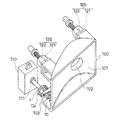
- FIG. 1 is a perspective view of a main part of a reflector and an actuator constituting a vehicular lamp according to an embodiment of the present invention.
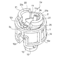
- FIG. 2 is a perspective view of the clip according to the embodiment of the present invention, and the capturing body is in the standby position.
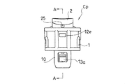
- FIG. 3 is a side view of the clip, and the capturing body is in the standby position.
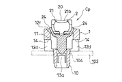
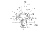
- FIG. 4 is a cross-sectional view taken along the line AA in FIG. 3, showing a part of the bracket of the reflector by an imaginary line, and the capturing body is in the standby position.
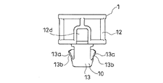
- FIG. 5 is a side view of the clip viewed from a direction different from FIG. 3 by 90 degrees, and the capturing body is in the standby position.
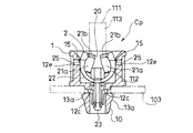
- FIG. 6 is a cross-sectional view taken along the line BB in FIG. 5, showing a part of the bracket of the reflector by an imaginary line, and the capturing body is in the standby position.
- FIG. 7 is a cross-sectional view of the main part of the clip showing the state in which the capturing body is pushed to the capturing position, with the bracket of the reflector and a part of the output shaft represented by imaginary lines.
- FIG. 8 is a cross-sectional view showing the state in which the capturing body is pushed to the capturing position, in which the bracket of the reflector and a part of the output shaft are represented by imaginary lines, and is viewed from a direction different from FIG. 7 by 90 degrees.
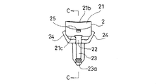
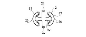
- FIG. 9 is a side view of the capturing body constituting the clip.
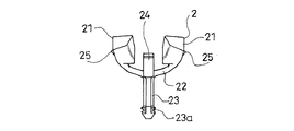
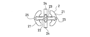
- FIG. 10 is a cross-sectional view taken along the line CC in FIG.
- FIG. 11 is a side view of the capturing body viewed from a direction different from that of FIG. 9 by 90 degrees.
- FIG. 12 is a plan view of the capturing body.
- FIG. 13 is a bottom view of the capturing body.
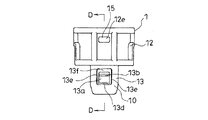
- FIG. 14 is a side view of a clip body constituting the clip.
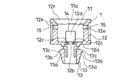
- 15 is a cross-sectional view taken along the line DD in FIG.
- FIG. 16 is a side view of the capturing body viewed from a direction different from that of FIG. 14 by 90 degrees.
- FIG. 17 is a plan view of the clip body.
- the clip Cp according to this embodiment is used to connect the reflector 100 constituting the vehicular lamp and the output shaft 111 of the actuator 110 that tilts the reflector 100 as necessary.
- the reflector 100 has a front surface opened and a reflecting surface 101 as an inner surface, which gradually narrows toward the back, and is provided with a valve (not shown) that can be replaced in the innermost portion 102.
- the reflector housing (not shown) is formed in a box shape with at least the front surface as a lens portion, and the reflector 100 is tilted and supported therein.
- the reflector 100 is supported on the back surface of the reflector housing at two upper portions thereof by a support member 120 including a ball shaft 121 attached to the reflector housing side and a ball bearing 122 attached to the reflector 100 side.
- the reflector 100 has a bracket 103 at the lower lower corner of the back surface thereof, and is attached to the outside of the back surface of the reflector housing body, and the output shaft of the actuator 110 that allows the output shaft 111 to enter the reflector housing body so as to move back and forth.
- 111 is connected with the bracket 103 via the clip Cp.
- the reflector 100 is housed in the reflector housing so that the outer surface of the reflector 100 is not in contact with the inner surface of the reflector housing. Then, by moving the output shaft 111 of the actuator 110 back and forth, the reflector 100 can be tilted and adjusted between a certain forward tilt state and a certain rear tilt state. Thereby, the optical axis of the light output from the vehicle lamp can be adjusted.
- a vehicular lamp is attached to a vehicle body panel to constitute a headlight of an automobile.
- the clip Cp includes an attachment portion 10 to the reflector 100 that is tiltably supported by a reflector housing constituting the vehicular lamp, and a spherical tip 112 of an output shaft 111 that is moved back and forth in the tilting actuator 110.
- the capturing body 2 is provided.
- the clip Cp is composed of two parts, a clip main body 1 and a capturing body 2.
- the clip body 1 is provided with the mounting portion 10 and a storage recess 11 of the capturing body 2.
- the clip body 1 includes a first tube portion 12 and a second tube portion 13 having a smaller diameter. Both the cylinder parts 12 and 13 are comprised so that the substantially cylindrical shape may be made.
- the first cylinder portion 12 has one end opened, the other end covered with a bottom plate 12 a, and the inside as the storage recess 11.
- the second cylinder portion 13 has both ends of the cylinder open, and one end of the cylinder is integrally connected to a substantially central portion of the bottom plate 12 a of the first cylinder portion 12.
- a communication hole 12b is formed in the center of the bottom plate 12a of the first cylinder portion 12 to allow the storage recess 11 and the inside of the second cylinder portion 13 to communicate with each other.
- elastic protrusions 12c protruding toward the inner side of the communication hole 12b are provided on both sides in the diameter direction of the communication hole 12b.
- a window hole 12d is formed on both sides of the first tube portion 12 in the diameter direction so as to communicate the inside and outside of the first tube portion 12.
- This window hole 12d is formed by notching the side part of the first cylinder part 12 between the position approximately in the cylinder axis direction of the first cylinder part 12 and the bottom plate 12a.
- the bottom plate 12a is also cut off in a range extending over the outer surface of the second cylindrical portion 13.
- the window edge located on the entrance 11a side of the storage recess 11 in the window hole 12d formed in this way functions as a hooked portion 14 described later.
- a through hole 12e is formed in each side portion of the first cylindrical portion 12 and located between the two locations where the window holes 12d and 12d are formed.
- the through hole 12 e is formed on the inlet 11 a side of the storage recess 11 in the first cylinder portion 12.
- the through hole 12e functions as an additional hooked portion 15 described later.
- elastic engagement pieces 13a are formed on the side portions of the second cylindrical portion 13 at both radial positions.
- Each elastic engagement piece 13a includes a pair of vertical grooves 13e and 13e formed along the cylinder axis of the second cylindrical portion 13, and a bottom plate 12a of the first cylindrical portion 12 in the pair of vertical grooves 13e and 13e.
- the side part of the 2nd cylinder part 13 is comprised by the horizontal groove 13f ranging between the groove ends located in the side.
- An engagement protrusion 13b is formed on the outer surface of the elastic engagement piece 13a.
- the distance between the top portions 13c of the engagement protrusions 13b of the pair of elastic engagement pieces 13a and 13a is made slightly larger than the hole diameter of the mounting hole 104 formed in the bracket 103.
- the distance between the engagement protrusion 13b of the elastic engagement piece 13a and the bottom plate 12a is substantially the same as or slightly larger than the thickness of the bracket 103.
- the pair of elastic engagement pieces 13a and 13a are elastically restored to engage with the bottom plate 12a.
- the clip body 1 is fastened to the bracket 103 by sandwiching the bracket 103 with the mating protrusion 13b. That is, in this embodiment, the second cylinder portion 13 functions as the mounting portion 10.
- the capturing body 2 is configured to be able to be pushed and moved from the standby position on the entrance 11 a side of the storage recess 11 of the clip body 1 toward the capture position on the back side of the storage recess 11. Further, the capturing body 2 projects the receiving port 20 side of the capturing body 2 from the storage recess 11 in the standby position so that the receiving port 20 is substantially equal to or larger than the diameter of the spherical tip 112, and The receiving port 20 is configured to be elastically deformed in accordance with the movement to the capturing position and to make the receiving port 20 smaller than the diameter of the spherical tip 112 at the capturing position.
- the capturing bodies 2 are connected to each other on the side facing the back side of the storage recess 11, that is, the side facing the bottom plate 12a of the first cylindrical portion 12, and opposite to the connecting side.
- This side is used as the receiving port 20 of the spherical tip 112, and has a pair of capture pieces 21, 21 having a curved inner surface 21a following the spherical surface of the spherical tip 112.
- each of the pair of capture pieces 21 and 21 is between the connection point 112a of the spherical tip 112 and the shaft end of the shaft main body 113 of the output shaft 111 and the top part 112b opposite to the connection point 112a. It has a size that covers the entire side in a certain range. Further, the pair of capture pieces 21 and 21 are connected to each other between connecting pieces 22 provided between the rear edge portion 21c facing the inner side of the storage recess 11 opposite to the side of the mouth edge portion 21b constituting the receiving port 20. Are connected by. With the connecting piece 22, the pair of capturing pieces 21, 21 are opposed to face the curved inner surface 21 a. In the illustrated example, the outer surfaces of the pair of capture pieces 21 and 21 are also curved surfaces.
- the connecting piece 22 is curved so that the receiving port 20 side is curved inside.
- the connecting piece 22 is configured to be elastically deformable, and the size of the receiving port 20 formed by the mouth edge portions 21b of the pair of capturing pieces 21 and 21 is substantially equal to the diameter of the spherical tip 112 before being deformed.
- the receiving port 20 is smaller than the diameter of the spherical tip 112 by elastic deformation in a direction larger than this and in a direction to reduce the curvature of the curvature of the connecting piece 22.
- the edge 21b of the receiving port 20 of the capturing body 2 is in contact with the output shaft 111 so as to surround the output shaft 111 at the capturing position, and the inner surface of the capturing body 2 is spherical.
- the tip 112 is configured to make surface contact. (FIG. 7, FIG. 8) That is, each of the edge portions 21b of the pair of capturing pieces 21 and 21 is configured to have a curvature following the peripheral surface of the shaft main body 113 of the output shaft 111. Between 21b and the said back edge part 21c, it is comprised so that it may have the said curved inner surface 21a.
- the capturing body 2 is further substantially along the cylinder axis of the first cylinder portion 12 by integrally connecting one end of the shaft to the position approximately in the middle of the length direction outside the connecting piece 22 and in the middle of the length direction.
- a shaft body 23 having the other end of the shaft entering the second cylindrical portion 13 through the communication hole 12b.
- a circumferential groove 23a is formed around the shaft center of the shaft body 23, and the elastic projecting piece 12c is engaged with the circumferential groove 23a so that the clip body 1 and the capturing body are engaged. 2 are combined in a state where the capturing body 2 is positioned at the standby position.
- the pair of capture pieces 21 and 21 project the mouth edge 21b side outward from the housing recess 11, and the receiving port 20 is substantially equal to or larger than the diameter of the spherical tip 112. is doing.
- the capturing body 2 can be pushed and moved from this standby position to the capturing position (FIG. 8) where the connecting piece 22 abuts against the bottom plate 12 a of the first cylindrical portion 12.
- the capturing body 2 can be moved to the capturing position by inserting the spherical tip 112 of the output shaft 111 into the capturing body 2 at the standby position and further inserting the output shaft 111 into the clip body 1.
- the capture piece 21 has its outer surface in contact with the circumferential taper surface portion 12f, and when this insertion operation is performed, the connection piece 22 is gradually elastically deformed by the circumferential taper surface portion 12f and a pair of capture pieces. The interval between 21 and 21 is gradually narrowed.
- the receiving port 20 becomes smaller than the diameter of the spherical tip 112, and the rim portion 21 b of the receiving port 20 comes into contact with the output shaft 111 so as to surround the output shaft 111. Since the inner surface is in surface contact with the spherical tip 112, the spherical tip 112 is stably held in the clip body 1. Thereby, the reflector 100 and the output shaft 111 can be stably combined through the clip Cp in a state in which the reflector 100 can be tilted. Since the capturing body 2 protrudes from the receiving port 20 at the standby position, it is easy to insert the spherical tip 112 of the output shaft 111 into the capturing body 2 at the standby position.
- the capture body 2 is elastically engaged with the engaged portion 14 of the clip body 1 as the capture body 2 moves from the standby position to the capture position.
- a hooking portion 24 that prevents the return to the position is formed.
- a hooking portion 24 is provided between the pair of capture pieces 21, 21.
- one end is integrally connected to the connecting piece 22 on both sides of the connecting piece 22 in the middle of the length direction, and the other end is protruded to the receiving port 20 side.
- a hook-like engagement portion 24 is provided that is positioned at a level between the edge portion 21b and the back edge portion 21c.
- the engagement taper portion 24 is gradually bent inward by the circumferential taper surface portion 12f, and enters the corresponding window hole 12d at the capture position.
- the window edge located on the side of the entrance 11a of the storage recess 11 in the window hole 12d is engaged as a hooked portion 14 so as to be hooked thereto.
- the additional engagement portion 15 of the clip body 1 is elastically engaged with the movement of the capture body 2 from the standby position to the capture position.
- an additional engagement portion 25 that prevents the capture body 2 from returning to the standby position is formed.
- additional hooking portions 25 each having a protruding shape are provided on the outer surface portions of the pair of capturing pieces 21, 21. Then, along with the movement of the capturing body 2 from the standby position to the capturing position, the additional engaging portion 25 comes into contact with the circumferential tapered surface portion 12f from the middle, and the additional engaging portion 25 corresponds to the corresponding through hole 12e at the capturing position. It enters by the bullet of the connecting piece 22, and this through hole 12 e is engaged with this as an additional engagement portion 15. Thereby, in this embodiment, the state where the spherical tip 112 is captured by the capturing body 2 is more stably maintained.
- the capturing body 2 is composed of a pair of capturing pieces 21, 21, but the capturing body 2 may be composed of three or more capturing pieces 21. Moreover, the provision of this property to the portion to be provided with the elastic deformation property in the clip Cp described above can be easily ensured by using the clip Cp as a synthetic resin molded product.
- the entire contents of the specification, claims, drawings and abstract of Japanese Patent Application No. 2010-021854 filed on Feb. 3, 2010 are cited herein as disclosure of the specification of the present invention. Incorporated.
Landscapes
- Engineering & Computer Science (AREA)
- General Engineering & Computer Science (AREA)
- Mechanical Engineering (AREA)
- Non-Portable Lighting Devices Or Systems Thereof (AREA)
- Clamps And Clips (AREA)
Abstract
捕捉体は、クリップ本体の収納凹部の入り口側にある待機位置において捕捉体の受け入れ口側を収納凹部内から突出させてこの受け入れ口を球状先端の直径と略等しいかこれより大きくし、かつ、捕捉位置への移動に伴って弾性変形されてこの捕捉位置において受け入れ口を球状先端の直径より小さくするように構成されている。捕捉位置において捕捉体の受け入れ口の口縁部が出力軸を取り巻くようにこの出力軸に接すると共に、捕捉体の内面が球状先端に面接触するように構成されている。
Description
この発明は、車両用灯具を構成するリフレクタと、このリフレクタを必要に応じて傾動させるアクチュエータの出力軸とを接続させ合わせるために用いられるクリップの改良に関する。
リフレクタに対する取り付け部を備えたクリップ本体に、捕捉体を押し込み移動可能に組み合わせてなり、待機位置にある捕捉体にリフレクタの傾動用のアクチュエータにおける前後動される出力軸の球状先端を納めた状態から出力軸をクリップ本体内に入れ込むことで、捕捉体を捕捉位置に押し込み移動させてリフレクタと出力軸とをクリップを介して接続させるものがある。(特許文献1参照)
この特許文献1のクリップにあっては、捕捉体は一対の捕捉片からなり、一対の捕捉片により構成される球状先端の受け入れ口を、前記待機位置では球状先端の直径より大きくし、前記捕捉位置ではこれより小さくする。これにより、球状先端の捕捉を可能としている。
しかし、この特許文献1のクリップにあっては、一対の捕捉片は内側を湾曲面としているものの、捕捉位置においては球状先端には線的に接触するに留まるものであった。
この発明が解決しようとする主たる問題点は、この種の車両用灯具を構成するリフレクタと、その傾動用のアクチュエータの出力軸とを接続させ合わせるクリップにおいて、クリップにおけるこの出力軸の保持(捕捉)状態をより良好なものとすると共に、この出力軸の球状先端のクリップへのはめ込みをより容易になし得るようにする点にある。
前記課題を達成するために、この発明にあっては、クリップを、車両用灯具を構成するリフレクタ収納体に傾動可能に支持されたリフレクタへの取り付け部と、
前記傾動用のアクチュエータにおける前後動される出力軸の球状先端の捕捉体とを備えたクリップであって、
クリップ本体には、前記取り付け部と捕捉体の収納凹部とが備えられており、
捕捉体は、クリップ本体の収納凹部の入り口側にある待機位置から収納凹部の奥側にある捕捉位置に向けて押し込み移動可能に構成されていると共に、
待機位置において捕捉体の受け入れ口側を前記収納凹部内から突出させてこの受け入れ口を球状先端の直径と略等しいかこれより大きくし、
かつ、捕捉位置への移動に伴って弾性変形されてこの捕捉位置において受け入れ口を球状先端の直径より小さくするように構成されており、
しかも、捕捉位置において捕捉体の受け入れ口の口縁部が出力軸を取り巻くようにこの出力軸に接すると共に、捕捉体の内面が球状先端に面接触するように構成されているものとした。
前記傾動用のアクチュエータにおける前後動される出力軸の球状先端の捕捉体とを備えたクリップであって、
クリップ本体には、前記取り付け部と捕捉体の収納凹部とが備えられており、
捕捉体は、クリップ本体の収納凹部の入り口側にある待機位置から収納凹部の奥側にある捕捉位置に向けて押し込み移動可能に構成されていると共に、
待機位置において捕捉体の受け入れ口側を前記収納凹部内から突出させてこの受け入れ口を球状先端の直径と略等しいかこれより大きくし、
かつ、捕捉位置への移動に伴って弾性変形されてこの捕捉位置において受け入れ口を球状先端の直径より小さくするように構成されており、
しかも、捕捉位置において捕捉体の受け入れ口の口縁部が出力軸を取り巻くようにこの出力軸に接すると共に、捕捉体の内面が球状先端に面接触するように構成されているものとした。
待機位置にある捕捉体に出力軸の球状先端を入れ込ませ、さらに出力軸をクリップ本体内に入れ込む操作をすることで、捕捉体を捕捉位置に移動させることができる。捕捉体が捕捉位置に移動されると受け入れ口は球状先端の直径より小さくなり、受け入れ口の口縁部は出力軸を取り巻くようにこれに接し、かつ、捕捉体の内面は球状先端に面接触することから、クリップ本体内に球状先端は安定的に保持される。これによりクリップを介してリフレクタと出力軸とをリフレクタの傾動を可能とした状態で安定的に組み合わせることができる。待機位置において捕捉体は受け入れ口から突出していることから、待機位置における捕捉体への出力軸の球状先端の入れ込みは容易である。
前記捕捉体に、待機位置から捕捉位置への捕捉体の移動に伴ってクリップ本体の被掛合部に弾発掛合して捕捉体の待機位置への復帰を阻止する掛合部を形成させておくことで、球状頭部を捕捉体により捕捉した状態を安定的に維持することができる。
捕捉体は、収納凹部の奥側に向けられた側で互いに連接され、この連接側と反対の側を球状先端の受け入れ口とし、かつ、球状先端の球面に倣った湾曲内面を持った一対の捕捉片を有するものとし、この一対の捕捉片間に掛合部を備えさせるようにすることが好ましい態様の一つとされる。この場合には、一対の捕捉片の外側に、待機位置から捕捉位置への捕捉体の移動に伴ってクリップ本体の追加被掛合部に弾発掛合して捕捉体の待機位置への復帰を阻止する追加掛合部を形成されておくことで、球状頭部を捕捉体により捕捉した状態をより安定的に維持することができる。
この発明にかかるクリップによれば、アクチュエータの出力軸の球状先端をクリップ本体内において安定的に保持することができると共に、この出力軸の球状先端のクリップへのはめ込みを容易になすことができる。
以下、図1~図17に基づいて、この発明の典型的な実施の形態について説明する。この実施の形態にかかるクリップCpは、車両用灯具を構成するリフレクタ100と、このリフレクタ100を必要に応じて傾動させるアクチュエータ110の出力軸111とを接続させ合わせるために用いられるものである。
リフレクタ100は、前面を開放させると共に、その内面を反射面101とし、奥に向かうに連れて次第に狭まり、最奥部102に図示しないバルブを取り替え可能に備えるようになっている。
リフレクタ収納体(図示は省略する。)は、少なくとも前面をレンズ部とした箱状をなし、その内部にリフレクタ100を傾動可能に納め支持するようになっている。図示の例では、リフレクタ100は、その上部二カ所において、リフレクタ収納体側に取り付けられたボール軸121とリフレクタ100側に取り付けられたボール軸受け122よりなる支持部材120によってリフレクタ収納体の背面に支持されている。また、リフレクタ100は、その背面の下部下隅にブラケット103を有しており、リフレクタ収納体の背面外側に取り付けられて出力軸111を前後動可能にリフレクタ収納体内に入り込ませたアクチュエータ110の出力軸111に対し、前記クリップCpを介してこのブラケット103を利用して接続されている。リフレクタ100は、その外面をリフレクタ収納体の内面に接しさせないようにした状態でリフレクタ収納体内に納められている。そして、アクチュエータ110の出力軸111を前後動させることにより、リフレクタ100を一定の前傾状態と一定の後傾状態の間で傾動調整できるようになっている。これによって、車両用灯具から出力される光の光軸を調整することができるようになっている。かかる車両用灯具は、車両のボディパネルに取り付けられて自動車のヘッドライトなどを構成することとなる。
前記クリップCpは、かかる車両用灯具を構成するリフレクタ収納体に傾動可能に支持されたリフレクタ100への取り付け部10と、前記傾動用のアクチュエータ110における前後動される出力軸111の球状先端112の捕捉体2とを備えている。かかるクリップCpは、クリップ本体1と捕捉体2との2パーツから構成されている。そして、このクリップ本体1に前記取り付け部10と捕捉体2の収納凹部11とが備えられている。
図示の例では、クリップ本体1は、第一筒部12と、これより小径の第二筒部13とを備えてなる。両筒部12、13共に、略円筒状をなすように構成されている。第一筒部12は筒一端を開放させ、筒他端を底板12aにより塞ぎ、その内部を前記収納凹部11としている。第二筒部13は、筒両端を共に開放させると共に、その筒一端を第一筒部12の底板12aの略中央部に一体に連接させている。
第一筒部12の底板12aの中央には収納凹部11と第二筒部13の内部とを連通させる連通穴12bが形成されている。この連通穴12bの孔縁部には、この連通穴12bの直径方向両側においてそれぞれ、連通穴12bの内方に向けて突き出す弾性突片12cが備えられている。
また、第一筒部12の側部には、この第一筒部12の直径方向両側においてそれぞれ、第一筒部12の内外を連通させる窓穴12dが形成されている。この窓穴12dは、第一筒部12の側部を第一筒部12の筒軸方向略中程の位置から底板12aまでの間において割り欠くことで形成されている。この窓穴12dの直下位置においては前記底板12aも第二筒部13の外面に亘る範囲で割り欠かれている。このように形成される窓穴12dにおける収納凹部11の入り口11a側に位置される窓縁が後述する被掛合部14として機能するようになっている。
また、第一筒部12の側部であって、二箇所の前記窓穴12d、12dの形成箇所の間に位置される箇所にはそれぞれ、貫通孔12eが形成されている。この貫通孔12eは第一筒部12における収納凹部11の入り口11a側に形成されている。図示の例では、かかる貫通孔12eが後述する追加被掛合部15として機能するようになっている。
また、かかる第一筒部12の内面部であって、前記収納凹部11の入り口11aと前記貫通孔12eの形成位置との間に位置される箇所には、収納凹部11の奥側に向かうに連れてこの第一筒部12の内径を狭める向きに傾斜した周回テーパー面部12fとなっている。
一方、第二筒部13の側部には、その直径方向両側位置にそれぞれ、弾性係合片13aが形成されている。各弾性係合片13aは、第二筒部13の筒軸に沿って形成された一対の縦割溝13e、13eと、この一対の縦割溝13e、13eにおける第一筒部12の底板12a側に位置される溝端間に亘る横割溝13fとにより第二筒部13の側部を区分することにより構成されている。この弾性係合片13aの外面部には係合突部13bが形成されている。この実施の形態では、前記ブラケット103に形成された取付穴104の穴径よりも一対の弾性係合片13a、13aの係合突部13bの頂部13c間の間隔がやや大きくなるようにしてある。また、かかる弾性係合片13aの係合突部13bと前記底板12aとの間の間隔がブラケット103の厚さと略同じかこれよりもやや大きくなるようにしてある。かかるブラケット103の取付穴104にリフレクタ100の背面側から第二筒部13を挿入するとこの取付穴104側に係合突部13bが接して一対の弾性係合片13a、13aはその基部13d側を変形中心として内方に撓みこの取付穴104への第二筒部13の挿入が許容される。係合突部13bの頂部13cが取付穴104の挿入先側の穴縁から前方に入り込む位置までこの挿入がなされると一対の弾性係合片13a、13aは弾性復帰され、前記底板12aと係合突部13bとの間でブラケット103を挟持してブラケット103にクリップ本体1が留め付けられる。(図8)すなわち、この実施の形態にあっては、かかる第二筒部13が前記取り付け部10として機能するようになっている。
次いで、前記捕捉体2は、クリップ本体1の収納凹部11の入り口11a側にある待機位置から収納凹部11の奥側にある捕捉位置に向けて押し込み移動可能に構成されている。また、かかる捕捉体2は前記待機位置において捕捉体2の受け入れ口20側を前記収納凹部11内から突出させてこの受け入れ口20を球状先端112の直径と略等しいかこれより大きくし、かつ、捕捉位置への移動に伴って弾性変形されてこの捕捉位置において受け入れ口20を球状先端112の直径より小さくするように構成されている。
この実施の形態にあっては捕捉体2は、収納凹部11の奥側に向けられた側、つまり前記第一筒部12の底板12aに向けられた側で互いに連接され、この連接側と反対の側を球状先端112の受け入れ口20とし、かつ、球状先端112の球面に倣った湾曲内面21aを持った一対の捕捉片21、21を有している。
図示の例では、かかる一対の捕捉片21、21はそれぞれ、球状先端112における出力軸111の軸主体113の軸端との連接箇所112aからこの連接箇所112aと反対の頭頂部112bとの間に亘る側部を一定の範囲で覆う大きさを備えている。また、一対の捕捉片21、21相互は、受け入れ口20を構成する口縁部21bの側と反対の収納凹部11の奥側に向けられた奥縁部21c間に渡し設けられた連接片22により連接されている。この連接片22により一対の捕捉片21、21は湾曲内面21aを向き合わせるように対置されている。図示の例では、一対の捕捉片21、21の外面も湾曲面となっている。この連接片22は受け入れ口20の側を湾曲内側とするように湾曲されている。かかる連接片22は弾性変形可能に構成されており、変形前の状態では一対の捕捉片21、21の口縁部21bによって形成される受け入れ口20の大きさは球状先端112の直径と略等しいかこれより大きく、この連接片22の湾曲の曲率を小さくする向きの弾性変形によってかかる受け入れ口20は球状先端112の直径より小さくなるようになっている。
そして、この実施の形態にあっては、前記捕捉位置において捕捉体2の受け入れ口20の口縁部21bが出力軸111を取り巻くようにこの出力軸111に接すると共に、捕捉体2の内面が球状先端112に面接触するように構成されている。(図7、図8)すなわち、前記一対の捕捉片21、21の口縁部21bはそれぞれ、出力軸111の軸主体113の周面に倣った湾曲を持つように構成され、この口縁部21bと前記奥縁部21cとの間は前記湾曲内面21aを持つように構成されている。
図示の例では、捕捉体2はさらに、連接片22の湾曲外側であってその長さ方向略中程の位置に軸一端を一体に連接させて、第一筒部12の筒軸に略沿って延び、かつ、軸他端を前記連通穴12bを通じて第二筒部13に入り込ませた軸体23を備えている。この軸体23の軸他端には、この軸体23の軸中心を巡る周回溝23aが形成されており、この周回溝23aに前記弾性突片12cを係合させてクリップ本体1と捕捉体2とがこの捕捉体2を前記待機位置に位置づけさせた状態で組み合わされるようになっている。(図4)この待機位置において、一対の捕捉片21、21は口縁部21b側を収納凹部11よりも外側に突き出させ、前記受け入れ口20は球状先端112の直径と略等しいかこれより大きくしている。捕捉体2はこの待機位置から連接片22を第一筒部12の底板12aに突き当てる捕捉位置(図8)まで押し込み移動可能となっている。
待機位置にある捕捉体2に出力軸111の球状先端112を入れ込ませ、さらに出力軸111をクリップ本体1内に入れ込む操作をすることで、捕捉体2を捕捉位置に移動させることができる。図示の例では、捕捉片21はその外面を前記周回テーパー面部12fに接しさせるようになっており、かかる入れ込み操作をするとこの周回テーパー面部12fにより連接片22は徐々に弾性変形され一対の捕捉片21、21間の間隔は徐々に狭められる。捕捉体2が捕捉位置に移動されると受け入れ口20は球状先端112の直径より小さくなり、受け入れ口20の口縁部21bは出力軸111を取り巻くようにこれに接し、かつ、捕捉体2の内面は球状先端112に面接触することから、クリップ本体1内に球状先端112は安定的に保持される。これによりクリップCpを介してリフレクタ100と出力軸111とをリフレクタ100の傾動を可能とした状態で安定的に組み合わせることができる。待機位置において捕捉体2は受け入れ口20から突出していることから、待機位置における捕捉体2への出力軸111の球状先端112の入れ込みは容易である。
この実施の形態にあっては、前記捕捉体2に、待機位置から捕捉位置への捕捉体2の移動に伴ってクリップ本体1の被掛合部14に弾発掛合して捕捉体2の待機位置への復帰を阻止する掛合部24が形成されている。具体的には、前記一対の捕捉片21、21間にかかる掛合部24が備えられている。図示の例では、前記連接片22の長さ方向略中程の位置の両側にそれぞれ、一端をこの連接片22に一体に連接させて受け入れ口20側に突きだし、他端を捕捉片21の口縁部21bと奥縁部21cとの間のレベルに位置させる片状をなす掛合部24を備えさせている。そして、待機位置から捕捉位置への捕捉体2の移動に伴って、前記周回テーパー面部12fにより掛合部24は徐々に内向きに撓められ、捕捉位置において対応する前記窓穴12dに入り込み、弾性復帰してこの窓穴12dにおける収納凹部11の入り口11a側に位置される窓縁を被掛合部14としてこれに掛合されるようになっている。(図7)これによりこの実施の形態にあっては、球状頭部を捕捉体2により捕捉した状態を安定的に維持している。
また、この実施の形態にあっては、一対の捕捉片21、21の外側に、待機位置から捕捉位置への捕捉体2の移動に伴ってクリップ本体1の追加被掛合部15に弾発掛合して捕捉体2の待機位置への復帰を阻止する追加掛合部25が形成されている。図示の例では、前記一対の捕捉片21、21の外面部にそれぞれ突起状をなす追加掛合部25を備えさせている。そして、待機位置から捕捉位置への捕捉体2の移動に伴って、途中から前記周回テーパー面部12fにこの追加掛合部25が接すると共に、捕捉位置において対応する前記貫通孔12eに追加掛合部25が連接片22の弾発により入り込み、この貫通孔12eを追加被掛合部15としてこれに掛合されるようになっている。これによりこの実施の形態にあっては、球状先端112を捕捉体2により捕捉した状態をより安定的に維持するようになっている。
図示の例では前記捕捉体2を一対の捕捉片21、21から構成しているが、三個以上の捕捉片21から捕捉体2を構成するようにしておくこともできる。また、以上に説明したクリップCpにおける弾性変形特性を備えるべき箇所へのこの特性の付与は、かかるクリップCpを合成樹脂の成形品とすることで容易に確保することができる。
2010年2月3日に出願された日本国特許出願第2010-021854号の明細書、特許請求の範囲、図面及び要約書の全内容をここに引用し、本発明の明細書の開示として、取り入れるものである。
2010年2月3日に出願された日本国特許出願第2010-021854号の明細書、特許請求の範囲、図面及び要約書の全内容をここに引用し、本発明の明細書の開示として、取り入れるものである。
Claims (4)
- 車両用灯具を構成するリフレクタ収納体に傾動可能に支持されたリフレクタへの取り付け部と、
前記傾動用のアクチュエータにおける前後動される出力軸の球状先端の捕捉体とを備えたクリップであって、
クリップ本体には、前記取り付け部と捕捉体の収納凹部とが備えられており、
捕捉体は、クリップ本体の収納凹部の入り口側にある待機位置から収納凹部の奥側にある捕捉位置に向けて押し込み移動可能に構成されていると共に、
待機位置において捕捉体の受け入れ口側を前記収納凹部内から突出させてこの受け入れ口を球状先端の直径と略等しいかこれより大きくし、
かつ、捕捉位置への移動に伴って弾性変形されてこの捕捉位置において受け入れ口を球状先端の直径より小さくするように構成されており、
しかも、捕捉位置において捕捉体の受け入れ口の口縁部が出力軸を取り巻くようにこの出力軸に接すると共に、捕捉体の内面が球状先端に面接触するように構成されていることを特徴とするクリップ。 - 捕捉体に、待機位置から捕捉位置への捕捉体の移動に伴ってクリップ本体の被掛合部に弾発掛合して捕捉体の待機位置への復帰を阻止する掛合部が形成されていることを特徴とする請求項1に記載のクリップ。
- 捕捉体は、収納凹部の奥側に向けられた側で互いに連接され、この連接側と反対の側を球状先端の受け入れ口とし、かつ、球状先端の球面に倣った湾曲内面を持った一対の捕捉片を有しており、
この一対の捕捉片間に掛合部が備えられていることを特徴とする請求項2に記載のクリップ。 - 一対の捕捉片の外側に、待機位置から捕捉位置への捕捉体の移動に伴ってクリップ本体の追加被掛合部に弾発掛合して捕捉体の待機位置への復帰を阻止する追加掛合部が形成されていることを特徴とする請求項3に記載のクリップ。
Priority Applications (1)
| Application Number | Priority Date | Filing Date | Title |
|---|---|---|---|
| CN201180008336.7A CN102741610B (zh) | 2010-02-03 | 2011-01-31 | 卡夹 |
Applications Claiming Priority (2)
| Application Number | Priority Date | Filing Date | Title |
|---|---|---|---|
| JP2010-021854 | 2010-02-03 | ||
| JP2010021854A JP5399282B2 (ja) | 2010-02-03 | 2010-02-03 | クリップ |
Publications (1)
| Publication Number | Publication Date |
|---|---|
| WO2011096372A1 true WO2011096372A1 (ja) | 2011-08-11 |
Family
ID=44355370
Family Applications (1)
| Application Number | Title | Priority Date | Filing Date |
|---|---|---|---|
| PCT/JP2011/051957 Ceased WO2011096372A1 (ja) | 2010-02-03 | 2011-01-31 | クリップ |
Country Status (3)
| Country | Link |
|---|---|
| JP (1) | JP5399282B2 (ja) |
| CN (1) | CN102741610B (ja) |
| WO (1) | WO2011096372A1 (ja) |
Cited By (6)
| Publication number | Priority date | Publication date | Assignee | Title |
|---|---|---|---|---|
| EP3299642A1 (de) * | 2016-09-12 | 2018-03-28 | ZKW Group GmbH | Fahrzeugscheinwerfer mit kugelgelenk |
| DE102017125771B4 (de) | 2017-11-03 | 2020-06-18 | Illinois Tool Works Inc. | Fahrzeugkomponenten-Befestiger mit verbesserter Vorverrastung |
| US20230060485A1 (en) * | 2018-07-17 | 2023-03-02 | Federal-Mogul Motorparts Llc | Fiber reinforced bearing for a ball socket assembly, ball socket assembly therewith and methods of construction thereof |
| DE102022129440A1 (de) | 2021-11-26 | 2023-06-01 | Illinois Tool Works Inc. | Befestigungsvorrichtung sowie Verfahren zur Befestigung von Bauteilen an Bolzen |
| US12385520B2 (en) * | 2020-06-12 | 2025-08-12 | Nifco Inc. | Ball joint |
| US20250296498A1 (en) * | 2024-03-21 | 2025-09-25 | Paccar Inc | Headlamp aiming system |
Citations (4)
| Publication number | Priority date | Publication date | Assignee | Title |
|---|---|---|---|---|
| JP2002543342A (ja) * | 1999-04-26 | 2002-12-17 | フィコ ケーブルス エス.エー. | 接続エレメント |
| JP2003536028A (ja) * | 2000-06-08 | 2003-12-02 | フィコ ケーブルス、 エス.エー. | 接続エレメント |
| JP2007042289A (ja) * | 2005-07-29 | 2007-02-15 | Koito Mfg Co Ltd | クリップ、および、車両用灯具 |
| JP2008144968A (ja) * | 2006-12-07 | 2008-06-26 | Stabilus Gmbh | ボールジョイント装置 |
-
2010
- 2010-02-03 JP JP2010021854A patent/JP5399282B2/ja not_active Expired - Fee Related
-
2011
- 2011-01-31 CN CN201180008336.7A patent/CN102741610B/zh not_active Expired - Fee Related
- 2011-01-31 WO PCT/JP2011/051957 patent/WO2011096372A1/ja not_active Ceased
Patent Citations (4)
| Publication number | Priority date | Publication date | Assignee | Title |
|---|---|---|---|---|
| JP2002543342A (ja) * | 1999-04-26 | 2002-12-17 | フィコ ケーブルス エス.エー. | 接続エレメント |
| JP2003536028A (ja) * | 2000-06-08 | 2003-12-02 | フィコ ケーブルス、 エス.エー. | 接続エレメント |
| JP2007042289A (ja) * | 2005-07-29 | 2007-02-15 | Koito Mfg Co Ltd | クリップ、および、車両用灯具 |
| JP2008144968A (ja) * | 2006-12-07 | 2008-06-26 | Stabilus Gmbh | ボールジョイント装置 |
Cited By (9)
| Publication number | Priority date | Publication date | Assignee | Title |
|---|---|---|---|---|
| EP3299642A1 (de) * | 2016-09-12 | 2018-03-28 | ZKW Group GmbH | Fahrzeugscheinwerfer mit kugelgelenk |
| DE102017125771B4 (de) | 2017-11-03 | 2020-06-18 | Illinois Tool Works Inc. | Fahrzeugkomponenten-Befestiger mit verbesserter Vorverrastung |
| US20230060485A1 (en) * | 2018-07-17 | 2023-03-02 | Federal-Mogul Motorparts Llc | Fiber reinforced bearing for a ball socket assembly, ball socket assembly therewith and methods of construction thereof |
| US12281670B2 (en) * | 2018-07-17 | 2025-04-22 | Federal-Mogul Motorparts Llc | Fiber reinforced bearing for a ball socket assembly, ball socket assembly therewith and methods of construction thereof |
| US12385520B2 (en) * | 2020-06-12 | 2025-08-12 | Nifco Inc. | Ball joint |
| DE102022129440A1 (de) | 2021-11-26 | 2023-06-01 | Illinois Tool Works Inc. | Befestigungsvorrichtung sowie Verfahren zur Befestigung von Bauteilen an Bolzen |
| US20230167843A1 (en) * | 2021-11-26 | 2023-06-01 | Illinois Tool Works Inc. | Fastening apparatus and method for fastening components to bolts |
| US12577975B2 (en) * | 2021-11-26 | 2026-03-17 | Illinois Tool Works Inc. | Fastening apparatus and method for fastening components to bolts |
| US20250296498A1 (en) * | 2024-03-21 | 2025-09-25 | Paccar Inc | Headlamp aiming system |
Also Published As
| Publication number | Publication date |
|---|---|
| CN102741610B (zh) | 2014-12-03 |
| JP2011159561A (ja) | 2011-08-18 |
| CN102741610A (zh) | 2012-10-17 |
| JP5399282B2 (ja) | 2014-01-29 |
Similar Documents
| Publication | Publication Date | Title |
|---|---|---|
| JP5399282B2 (ja) | クリップ | |
| US20150042804A1 (en) | In-vehicle camera | |
| US20110286228A1 (en) | Vehicle headlight and assembling method thereof | |
| JP3883339B2 (ja) | 車両用灯具 | |
| JPH08203306A (ja) | 車輌用ヘッドランプ | |
| JP4508972B2 (ja) | クリップ、および、車両用灯具 | |
| JP5722926B2 (ja) | 成形されたランプソケット | |
| US10293754B2 (en) | Mirror device for vehicle | |
| JP2006126673A (ja) | レンズの取付構造 | |
| CN112721796B (zh) | 贯穿式尾灯和具有该贯穿式尾灯的车辆 | |
| JP2019100366A (ja) | 車両のブリーザプラグ | |
| CN113280303A (zh) | 车灯光学元件、前照灯模组、车灯和车辆 | |
| US5947757A (en) | Lever-type connector | |
| JP6592040B2 (ja) | 車体構造 | |
| JP2020152253A (ja) | ホールプラグ | |
| JP2007042288A (ja) | クリップ、および、車両用灯具 | |
| JP2016150723A (ja) | 車両用ルームミラー | |
| JP2012251567A (ja) | ボールジョイント | |
| CN212921448U (zh) | 清洗器后喷嘴安装机构及扰流板 | |
| JP7608313B2 (ja) | フック構造及びこれを用いた車両用灯具 | |
| JP2006309121A5 (ja) | ||
| KR102132870B1 (ko) | 차량용 램프 | |
| JP5613075B2 (ja) | 車両用灯具 | |
| JP2011187397A (ja) | 車両用灯具のワイヤーハーネス保持構造 | |
| WO2026094386A1 (ja) | コネクタ装置 |
Legal Events
| Date | Code | Title | Description |
|---|---|---|---|
| WWE | Wipo information: entry into national phase |
Ref document number: 201180008336.7 Country of ref document: CN |
|
| 121 | Ep: the epo has been informed by wipo that ep was designated in this application |
Ref document number: 11739720 Country of ref document: EP Kind code of ref document: A1 |
|
| NENP | Non-entry into the national phase |
Ref country code: DE |
|
| 122 | Ep: pct application non-entry in european phase |
Ref document number: 11739720 Country of ref document: EP Kind code of ref document: A1 |