WO2011090007A1 - 車載用アンテナ装置 - Google Patents
車載用アンテナ装置 Download PDFInfo
- Publication number
- WO2011090007A1 WO2011090007A1 PCT/JP2011/050693 JP2011050693W WO2011090007A1 WO 2011090007 A1 WO2011090007 A1 WO 2011090007A1 JP 2011050693 W JP2011050693 W JP 2011050693W WO 2011090007 A1 WO2011090007 A1 WO 2011090007A1
- Authority
- WO
- WIPO (PCT)
- Prior art keywords
- vehicle
- filter
- antenna device
- coaxial cable
- amplifier circuit
- Prior art date
- Legal status (The legal status is an assumption and is not a legal conclusion. Google has not performed a legal analysis and makes no representation as to the accuracy of the status listed.)
- Ceased
Links
Images



Classifications
-
- H—ELECTRICITY
- H01—ELECTRIC ELEMENTS
- H01Q—ANTENNAS, i.e. RADIO AERIALS
- H01Q1/00—Details of, or arrangements associated with, antennas
- H01Q1/27—Adaptation for use in or on movable bodies
- H01Q1/32—Adaptation for use in or on road or rail vehicles
- H01Q1/325—Adaptation for use in or on road or rail vehicles characterised by the location of the antenna on the vehicle
- H01Q1/3291—Adaptation for use in or on road or rail vehicles characterised by the location of the antenna on the vehicle mounted in or on other locations inside the vehicle or vehicle body
-
- H—ELECTRICITY
- H01—ELECTRIC ELEMENTS
- H01Q—ANTENNAS, i.e. RADIO AERIALS
- H01Q1/00—Details of, or arrangements associated with, antennas
- H01Q1/52—Means for reducing coupling between antennas; Means for reducing coupling between an antenna and another structure
-
- H—ELECTRICITY
- H01—ELECTRIC ELEMENTS
- H01Q—ANTENNAS, i.e. RADIO AERIALS
- H01Q23/00—Antennas with active circuits or circuit elements integrated within them or attached to them
-
- H—ELECTRICITY
- H01—ELECTRIC ELEMENTS
- H01Q—ANTENNAS, i.e. RADIO AERIALS
- H01Q9/00—Electrically-short antennas having dimensions not more than twice the operating wavelength and consisting of conductive active radiating elements
- H01Q9/04—Resonant antennas
- H01Q9/16—Resonant antennas with feed intermediate between the extremities of the antenna, e.g. centre-fed dipole
- H01Q9/26—Resonant antennas with feed intermediate between the extremities of the antenna, e.g. centre-fed dipole with folded element or elements, the folded parts being spaced apart a small fraction of operating wavelength
Definitions
- the present invention relates to a vehicle-mounted antenna device mounted on a vehicle, and more particularly to a vehicle-mounted antenna device in which an antenna element and a receiver are arranged at positions separated from each other and connected by a cable.
- the coaxial cable connecting the antenna element and the receiver is routed in an inconspicuous place such as the bottom of the car body, the coaxial cable is close to or connected to the metal part of the car body (hereinafter referred to as the car body metal part). Will be routed. While many UHF antennas are balanced, the coaxial cable and the amplifier circuit for amplifying the received signal are non-balanced circuits. Therefore, a mismatch occurs between the two and a common mode current is generated in the coaxial cable. This common mode current significantly deteriorates the shielding characteristics of the coaxial cable, and noise from the vehicle body metal part easily flows into the coaxial cable.
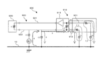
- FIG. 8 is an equivalent circuit diagram when a conventional vehicle-mounted antenna device 900 is arranged close to the vehicle body metal part 10.
- 7 (a) and 7 (b) are schematic configuration diagrams of an antenna unit 910 constituting a conventional on-vehicle antenna device 900, FIG. 7 (a) is a front view, and FIG. 7 (b) is a rear view. is there.
- FIG. 8 shows an equivalent circuit when the antenna unit 910 is installed at a position away from the receiver, and the coaxial cable connecting the antenna unit 910 is routed close to the metal part of the vehicle body.
- the antenna unit 910 is, for example, a broadband vehicle-mounted antenna used in the UHF frequency band.
- the antenna unit 910 includes a feeding element 911 and a parasitic element 912, the feeding element 911 is connected to the amplifier circuit 913, and the parasitic element 912 is connected to a ground plate 915 provided on the back surface of the circuit board 914. Yes.
- the amplifier circuit 913 is connected to the center conductor 921 of the coaxial cable 920, and the ground plane 915 is connected to the outer conductor 922 of the coaxial cable 920.
- the capacitance formed between the vehicle body metal part 10 and the outer conductor 922 of the coaxial cable 920 is divided into C1 and C2, but here, the capacitance at the position where noise is mixed into the outer conductor 922 is shown. It is assumed that C1 is a capacitance formed at other positions, and C2.
- the current I1 flowing through the vehicle-mounted antenna device 900 via the outer conductor 922 is indicated by I2 to I5.
- a part (current I2) of the common mode noise current I1 returns from the outer conductor 922 to the vehicle body metal part 10 via the capacitor C2, and the remaining current I3 flows into the circuit board 914.
- the currents I4 and I5 return to the vehicle body metal part 10 via the parasitic elements 912 and the capacitances C3 and C4 between the power supply element 911 and the vehicle body metal part 10, respectively.
- the voltage drop generated by the input impedance Z_A and the current I5 becomes a voltage input to the amplifier circuit 913, and is amplified by the amplifier circuit 913 and received by the receiver 930 as noise in the normal mode, which deteriorates the antenna characteristics. End up.
- the current I5 passing through the input impedance Z_A it is preferable to reduce the current I5 passing through the input impedance Z_A.
- the current I3 passing through the outer conductor 922 of the coaxial cable 920 is reduced (first method), or the current I4 flowing into the parasitic element 912 side is increased to increase the current I5.
- a method (second method) for reducing the above is conceivable.
- the impedance between the feeding element 911 and the vehicle body metal part 10 is Z_F and the impedance between the parasitic element 912 and the body metal part 10 is Z_G
- the current I5 can be reduced by making the impedance Z_G relatively small with respect to (Z_A + Z_F).
- Z_G conventionally, countermeasures for increasing the parasitic element 912 or increasing the capacitance C3 by bringing the parasitic element 912 close to the vehicle body metal part 10 are known.
- Z_G is set to 0 by directly connecting the parasitic element 912 to the vehicle body metal part 10.
- the capacitance C2 varies greatly depending on how the coaxial cable 920 is arranged.
- the noise characteristics also fluctuate, and stable antenna characteristics cannot be obtained.
- the second method also has problems such as difficulty in downsizing the antenna unit and severe restrictions on the shape, mounting position, and mounting conditions of the antenna unit.
- the present invention has been made to solve the above-described problem, and an object thereof is to provide a vehicle-mounted antenna device that can reduce the influence of common mode noise and obtain stable antenna characteristics.
- an antenna unit having a feeding element and a parasitic element, a circuit board having a ground plane on the back surface, and reception received by the antenna unit mounted on the circuit board.
- An in-vehicle antenna device comprising an amplifier circuit that amplifies a signal and a coaxial cable that electrically connects the amplifier circuit and a receiver, and reduces common mode noise mixed in an outer conductor of the coaxial cable And a filter for further comprising.
- the filter is connected between the amplifier circuit and the coaxial cable, the feeding element is connected to the amplifier circuit, and the parasitic element is connected to the ground plane. It is connected.
- the filter is disposed between the amplifier circuit and the antenna unit, the power feeding element is connected to the amplifier circuit via the filter, and the parasitic power is supplied.
- An element is connected to the ground plane through the filter.
- Another aspect of the vehicle-mounted antenna device of the present invention is characterized in that the feeding element and the parasitic element are arranged substantially parallel to a connection direction in which the coaxial cable is connected to the amplifier circuit.
- the filter is a common mode choke coil that blocks common mode noise mixed in an outer conductor of the coaxial cable.
- the filter is a choke coil for increasing impedance on the circuit board side as viewed from the outer conductor of the coaxial cable.
- Another aspect of the vehicle-mounted antenna device according to the present invention is characterized in that the antenna unit has a broadband reception characteristic in the UHF frequency band.
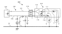
- FIG. 3 is a configuration diagram showing a schematic configuration of the vehicle-mounted antenna device 200 and the receiving system 240 of the present embodiment.
- FIG. 4 is a diagram illustrating the vehicle-mounted antenna device 200 of the present embodiment placed close to the vehicle body metal part 10.
- the on-vehicle antenna device 200 of the present embodiment is configured by an antenna unit 210 and a coaxial cable 120 with a connector that electrically connects the antenna unit 210 and the receiver 130.
- the antenna unit 210 includes a feeding element 111, a parasitic element 112, and a circuit board 114.
- An amplifier circuit 113 is mounted on the front surface of the circuit board 114, an electrode pattern serving as a ground plate 115 of the amplifier circuit 113 is disposed on the back surface, and a filter is disposed on the coaxial cable 120 side of the circuit board 114.
- the feed element 111 is connected to the + input of the amplifier circuit 113, and the parasitic element 112 is connected to the ground plate 115 of the amplifier circuit 113.
- the output of the amplifier circuit 113 is connected to the center conductor 121 of the coaxial cable 120 via the filter 216, and the ground plane 115 is also connected to the outer conductor 122 of the coaxial cable via the filter 216.
- a signal from the vehicle-mounted antenna device 200 is transmitted to the receiver 130 via the coaxial cable 120.
- the present embodiment is characterized in that the filter 216 is connected between the amplifier circuit 113 and the coaxial cable 120.
- the receiver 130 is installed at a different position away from the antenna element.
- 120 is routed a relatively long distance.
- the coaxial cable 120 has a center conductor 111 and an outer conductor 112, and is routed in an inconspicuous place such as the bottom of the vehicle body. Therefore, at least a part of the coaxial cable 120 is close to the vehicle body metal portion 10, and common mode noise is likely to be mixed from the vehicle body metal portion 10 to the outer conductor 112.
- capacitors stray capacitances (hereinafter simply referred to as “capacitances”) formed by disposing the antenna unit 210 and the coaxial cable 120 close to the vehicle body metal part 10 are indicated by capacitances C1 to C4. Between the body metal part 10 and the outer conductor 122 of the coaxial cable 120, a capacitor C1 at a position where noise is mixed and a capacitor C2 at other positions are formed. Capacitors C3 and C4 are formed between the vehicle body metal portion 10 and the power feeding element 111 and the parasitic element 112, respectively.
- the current of noise mixed into the outer conductor 122 via the capacitor C1 is denoted by I1, and the current I1 flows through the vehicle antenna device 200 via the outer conductor 122 as I2 to I5. Show. Of the current I1, part of the current I2 returns from the outer conductor 122 to the vehicle body metal part 10 via the capacitor C2, and the remaining current I3 flows into the circuit board 114 via the filter 216.
- the currents I4 and I5 return to the vehicle body metal part 10 via the parasitic elements 112 and the capacitances C3 and C4 between the power supply element 111 and the vehicle body metal part 10, respectively.
- a voltage drop caused by the input impedance Z_A and the current I5 flows into the amplifier circuit 113 as a voltage input, it is amplified by the amplifier circuit 113 and received by the receiver 130 as normal mode noise, which deteriorates the antenna characteristics. I will let you.
- a filter 216 is connected between the amplifier circuit 113 and the coaxial cable 120 in order to reduce such normal mode noise.
- the filter 216 is connected between the coaxial cable 120 and the amplifier circuit 113.
- the filter 216 has a high impedance with respect to I3, which is a current derived from common mode noise, and does not affect a normal mode signal from the antenna unit 210 to the receiver 130.
- the filter 216 is common.
- a mode choke filter is connected. Accordingly, the filter 216 can block the common mode at the connection point between the circuit board 114 and the coaxial cable 120 without affecting the signal in the normal mode. Inflow into the amplifier circuit 113 can be prevented.
- the impedance on the amplifier circuit 114 side viewed from the outer conductor 122 of the coaxial cable 120 increases by the impedance Z_CMC of the filter 216.
- the current I3 flowing through the ground plane 115 of the substrate 114 is reduced.
- the effect which reduces the electric current I3 can be acquired similarly to the conventional noise countermeasure (1st method), without being influenced by the wiring position of the coaxial cable 120.
- the conventional noise countermeasure second method
- the common mode current from the coaxial cable 120 to the amplifier circuit 113 is blocked by the filter 216.
- the common mode current from the ground plane 115 of the amplifier circuit 113 to the antenna elements 111 and 112 is not inhibited, the ground plane 115 is not fed. Since it can be designed to operate as a part of the antenna element 112 and space can be used efficiently and efficiently, the antenna size can be designed to be maximized in a limited mounting space. Thus, good antenna characteristics can be obtained.
- the common mode noise can be reduced by the filter 216 regardless of the balanced or unbalanced type of the antenna elements 111 and 112.
- the high impedance characteristic for the common mode does not depend on the wavelength, it is possible to easily cope with downsizing of the filter 216 and widening of the antenna elements 111 and 112. Further, there are no restrictions on the shape and mounting position of the antenna unit 210.
- the filter 216 is connected between the amplifier circuit 113 and the coaxial cable 120, thereby arranging the coaxial cable 120 and the antenna unit 110.
- the common mode noise current I3 flowing into the amplifier circuit 113 can be reduced without being affected by the position.
- normal mode noise transmitted from the amplifier circuit 113 to the receiver 130 can be reduced, and the antenna size can be designed to be as large as possible within a limited mounting space. Since the height can be increased, good antenna characteristics can be obtained.
- the vehicle-mounted antenna device 200 of the present embodiment can obtain stable antenna characteristics without being affected by the position of the coaxial cable 120. Further, there are no restrictions on the shape and mounting position of the antenna unit 210.
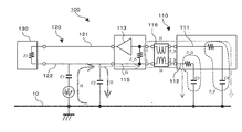
- FIG. 1 is a configuration diagram showing a schematic configuration of the vehicle-mounted antenna device 100 of the present embodiment
- FIG. 2 is an equivalent when the vehicle-mounted antenna device 100 of the present embodiment is arranged close to the vehicle body metal part 10. It is a circuit diagram.
- the filter 216 is disposed between the coaxial cable 120 and the amplifier circuit 113.
- the amplifier circuit 113, the feeding element 111, and the parasitic element 112 are disposed.
- the filter 116 is connected between the two. The filter 116 can reduce the current I5 and prevent the common mode noise from flowing into the amplifier circuit 113.
- the filter 116 is connected between the amplifier circuit 113 and the feeding element 111 and the parasitic element 112. A balun can be used as the filter 116.
- An antenna that targets the UHF band or longer wavelengths cannot operate in perfect equilibrium if the metal is in close proximity. Even in the vehicle-mounted antenna device 100 according to the present embodiment, since the vehicle body metal part 10 is close, the vehicle-mounted antenna device 100 hardly operates in a completely balanced state. If a forced balun is used under conditions where it cannot operate in a perfectly balanced state, the antenna element may be unbalanced so that good antenna characteristics may not be obtained.
- a float balun (choke coil) is used as the filter 116.
- the impedance for the currents I4 and I5 increases, and the currents I4 and I5 decrease.
- the impedance on the amplifier circuit 113 side viewed from the outer conductor 122 is increased, and the current I3 can also be reduced.
- the effect which reduces the electric current I3 can be acquired similarly to the conventional noise countermeasure (1st method), without being influenced by the wiring position of the coaxial cable 120.
- FIG. As a result, normal mode noise transmitted from the amplifier circuit 113 to the receiver 130 can be reduced, and good antenna characteristics can be obtained.
- I5 I3 ⁇ (Z_B + Z_G) / (Z_A + 2 ⁇ Z_B + Z_F + Z_G)
- Z_A is the input impedance between the + side input and ⁇ side input of the amplifier circuit 113
- Z_B is the impedance of the filter 116
- Z_F is the impedance between the feeding element 111 and the vehicle body metal part 10
- Z_G is nothing. This is the impedance between the power feeding element 112 and the vehicle body metal part 10.
- the impedance Z_B of the filter 116 In order to enhance the noise reduction effect of the filter 116, it is preferable to increase the impedance Z_B of the filter 116 so that the impedance on the circuit board 114 side as viewed from the outer conductor 122 is increased. As a result, I3 can be reduced.
- Z_B when Z_B is sufficiently large, it can be seen from the above equation that the effects of impedances Z_F and Z_G are relatively small. As a result, it cannot be used together with the conventional noise countermeasure (second method) in which the impedance Z_G is reduced and the current I4 is increased, so that the effect is limited compared to the first embodiment. .
- the ground plane 115 cannot be designed as a part of the parasitic element as in the first embodiment, the antenna size is also smaller than that in the first embodiment.
- the filter 116 is connected between the circuit board 114 and the antenna elements 111 and 112, thereby arranging the coaxial cable 120 and the antenna unit 110.
- the current I5 flowing on the line side to which the amplifier circuit 113 is connected can be reduced without being affected by the installation position of.
- normal mode noise flowing from the amplifier circuit 113 to the receiver 130 can be reduced, and good antenna characteristics can be obtained.
- the vehicle-mounted antenna device 100 according to the present embodiment can obtain stable antenna characteristics without being affected by the routing position of the coaxial cable 120 or the like. Further, there are no restrictions on the shape and mounting position of the antenna unit 110.
- the in-vehicle antenna device 200 was mounted on a vehicle and a running experiment was performed. Below, the verification result by driving
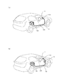
- the antenna unit 210 is mounted on the dashboard 11, the receiver 130 is installed under the rear seat, and a coaxial cable 120 is connected therebetween.
- the reception signal by the antenna unit 210 is the Tokyo Tower DTV broadcast radio wave 27ch.
- routing condition A when the coaxial cable 120 is routed in contact with the vehicle body metal part 10 (hereinafter referred to as routing condition A), the coaxial cable 120 is connected to the dashboard 11 as shown in FIG. When the cable is placed in contact with the vehicle body metal part 10 (hereinafter referred to as installation condition B). To do).
- the cable bending portion 12 of the coaxial cable 120 is in a state of receiving radio waves, like the antenna elements 111 and 112.
- the received power increases compared to the case of the routing condition A.
- Various electrical wirings are routed in the dashboard 11, and the electromagnetic noise level is high in the vicinity thereof. Therefore, in the case of the routing condition B, noise is easily received.
- a vehicle-mounted antenna device that does not have the filter 216 (hereinafter referred to as a comparative example antenna device) is mounted on a vehicle under the same conditions as the vehicle-mounted antenna device 200 of the present embodiment, and a running experiment is performed. It is carried out. Each driving experiment is equipped with a GPS to obtain vehicle position information.
- Received power difference (point i) received power (routing condition B, point i) ⁇ received power (routing condition A, point i)
- CNR difference (point i) CNR (route condition B, point i) ⁇ CNR (route condition A, point i)
- the reception power difference and the CNR difference of the above formula are calculated for each of the case where the vehicle-mounted antenna device 200 is mounted and the case where the comparative antenna device is mounted.
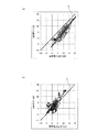
- FIG. 6 shows experimental results plotted with the received power difference as a horizontal axis and the CNR difference as a vertical axis.
- the reception power difference and the CNR difference are considered to indicate the magnitude of the influence of the change in the reception power and the CNR due to the cable deflection portion 12 in the case of the routing condition B.
- a straight line C having a slope 1 passing through the origin is a position plotted when the received power change and the CNR change are the same. That is, the amount of plot deviation from the straight line C indicates the difference in noise inflow between the cable routing conditions A and B. That is, when the plot is distributed on the straight line C, it is shown that there is no influence of the noise change due to the cable bending portion 12.
- FIG. 6A shows an experimental result when the comparative antenna device without the filter 216 is mounted
- FIG. 6B shows an experiment when the vehicle-mounted antenna device 200 of this embodiment is mounted. Results are shown. From FIG. 6A, when the filter 216 is not provided, the experimental data is distributed about 5 dB to the right of the straight line C. That is, when the same received power is obtained, it means that the CNR is deteriorated by about 5 dB due to the flexible portion 12 of the cable. When the filter 216 is not provided, it indicates that noise cannot be prevented from flowing in due to routing conditions such as cable deflection.
- the plot is distributed around the straight line C.
- the use of the filter 216 reduces the inflow of the common mode noise received by the cable at the cable bending portion 12 to the amplifier circuit. That is, in the in-vehicle antenna device 200 of the present embodiment in which the filter 216 is disposed between the amplifier circuit 113 and the coaxial cable 120, it is possible to reduce the influence of common mode noise flowing from the vehicle body metal part 10. It is possible to obtain stable antenna characteristics that are not affected by the routing conditions of the coaxial cable 120 or the like.
Landscapes
- Engineering & Computer Science (AREA)
- Remote Sensing (AREA)
- Details Of Aerials (AREA)
- Support Of Aerials (AREA)
Priority Applications (1)
| Application Number | Priority Date | Filing Date | Title |
|---|---|---|---|
| EP11734613.0A EP2528164A4 (en) | 2010-01-21 | 2011-01-18 | ANTENNA DEVICE FOR USE IN A VEHICLE |
Applications Claiming Priority (2)
| Application Number | Priority Date | Filing Date | Title |
|---|---|---|---|
| JP2010011281A JP5547500B2 (ja) | 2010-01-21 | 2010-01-21 | 車載用アンテナ装置 |
| JP2010-011281 | 2010-01-21 |
Publications (1)
| Publication Number | Publication Date |
|---|---|
| WO2011090007A1 true WO2011090007A1 (ja) | 2011-07-28 |
Family
ID=44306810
Family Applications (1)
| Application Number | Title | Priority Date | Filing Date |
|---|---|---|---|
| PCT/JP2011/050693 Ceased WO2011090007A1 (ja) | 2010-01-21 | 2011-01-18 | 車載用アンテナ装置 |
Country Status (3)
| Country | Link |
|---|---|
| EP (1) | EP2528164A4 (https=) |
| JP (1) | JP5547500B2 (https=) |
| WO (1) | WO2011090007A1 (https=) |
Families Citing this family (4)
| Publication number | Priority date | Publication date | Assignee | Title |
|---|---|---|---|---|
| JP6195502B2 (ja) * | 2013-10-30 | 2017-09-13 | 双葉電子工業株式会社 | アンテナ装置 |
| TWI626787B (zh) * | 2016-09-26 | 2018-06-11 | 群邁通訊股份有限公司 | 天線結構及具有該天線結構之無線通訊裝置 |
| JP7488777B2 (ja) * | 2021-01-27 | 2024-05-22 | 株式会社ヨコオ | 端子接続構造、車載用アンテナ装置、端子接続構造の組み立て方法 |
| DE112023006334T5 (de) * | 2023-07-06 | 2026-02-26 | Mitsubishi Electric Corporation | Antenneneinrichtung |
Citations (4)
| Publication number | Priority date | Publication date | Assignee | Title |
|---|---|---|---|---|
| JPH05343910A (ja) * | 1992-06-10 | 1993-12-24 | Sony Corp | 移動体アンテナ |
| JP2008153738A (ja) | 2006-12-14 | 2008-07-03 | Yokowo Co Ltd | 広帯域化ループアンテナ |
| JP2009135760A (ja) * | 2007-11-30 | 2009-06-18 | Moda Technology:Kk | 低放射ノイズ電子機器、プラグまたはアダプタ付伝送線路接続ケーブル、および電子機器の放射ノイズ除去方法 |
| JP2009225429A (ja) * | 2008-02-18 | 2009-10-01 | Mitsumi Electric Co Ltd | アンテナ装置および複合アンテナ装置 |
Family Cites Families (4)
| Publication number | Priority date | Publication date | Assignee | Title |
|---|---|---|---|---|
| DE3405044C1 (de) * | 1984-02-13 | 1985-08-29 | Rohde & Schwarz GmbH & Co KG, 8000 München | Aktive Dipolantenne |
| TW423180B (en) * | 1997-01-31 | 2001-02-21 | Terajima Fumitaka | Glass antenna device for an automobile |
| DE10322186B3 (de) * | 2003-05-16 | 2004-12-02 | Karl Fischer | Kurze Endgespeiste Dipolantenne |
| WO2009053404A1 (en) * | 2007-10-24 | 2009-04-30 | Tomtom International B.V. | Antenna arrangement with reduced comm-mode signal |
-
2010
- 2010-01-21 JP JP2010011281A patent/JP5547500B2/ja not_active Expired - Fee Related
-
2011
- 2011-01-18 WO PCT/JP2011/050693 patent/WO2011090007A1/ja not_active Ceased
- 2011-01-18 EP EP11734613.0A patent/EP2528164A4/en not_active Withdrawn
Patent Citations (4)
| Publication number | Priority date | Publication date | Assignee | Title |
|---|---|---|---|---|
| JPH05343910A (ja) * | 1992-06-10 | 1993-12-24 | Sony Corp | 移動体アンテナ |
| JP2008153738A (ja) | 2006-12-14 | 2008-07-03 | Yokowo Co Ltd | 広帯域化ループアンテナ |
| JP2009135760A (ja) * | 2007-11-30 | 2009-06-18 | Moda Technology:Kk | 低放射ノイズ電子機器、プラグまたはアダプタ付伝送線路接続ケーブル、および電子機器の放射ノイズ除去方法 |
| JP2009225429A (ja) * | 2008-02-18 | 2009-10-01 | Mitsumi Electric Co Ltd | アンテナ装置および複合アンテナ装置 |
Non-Patent Citations (1)
| Title |
|---|
| See also references of EP2528164A4 * |
Also Published As
| Publication number | Publication date |
|---|---|
| EP2528164A1 (en) | 2012-11-28 |
| EP2528164A4 (en) | 2013-08-07 |
| JP2011151623A (ja) | 2011-08-04 |
| JP5547500B2 (ja) | 2014-07-16 |
Similar Documents
| Publication | Publication Date | Title |
|---|---|---|
| JP5153300B2 (ja) | アンテナ | |
| CN104183900B (zh) | 车辆用天线 | |
| EP3101733B1 (en) | Glass antenna | |
| JP5861455B2 (ja) | アンテナ装置 | |
| WO2018203485A1 (ja) | アンテナ装置 | |
| AU2017275918B2 (en) | Glass antenna | |
| JP6461061B2 (ja) | アンテナ装置 | |
| JP4535007B2 (ja) | 車載統合アンテナ装置の搭載構造 | |
| JP7228466B2 (ja) | アンテナ装置 | |
| JPWO2015137108A1 (ja) | 自動車用ガラスアンテナ | |
| US20170069960A1 (en) | Antenna | |
| JP5547500B2 (ja) | 車載用アンテナ装置 | |
| CN114336000A (zh) | 车载用天线装置 | |
| CN112186355A (zh) | 天线模块及车机装置 | |
| JP2006311478A (ja) | 円偏波マイクロストリップアンテナ及び円偏波マイクロストリップアンテナ装置 | |
| US9203163B2 (en) | Antenna assembly | |
| JP2009516971A (ja) | マルチバンド全方向性アンテナ | |
| WO2013153784A1 (ja) | アンテナ装置 | |
| US6906672B1 (en) | Planar Antenna Arrangement | |
| JP2012175579A (ja) | ガラスアンテナ及び窓ガラス、並びにそれらを備えるアンテナ装置 | |
| WO2013136741A1 (ja) | アンテナ装置 | |
| EP4262022A1 (en) | Antenna device | |
| US20090058742A1 (en) | Glass antenna for vehicle | |
| JP5867416B2 (ja) | ガラスアンテナ及びそれを備える車両用窓ガラス | |
| JP2011101191A (ja) | 車両用ガラスアンテナ及び車両用窓ガラス |
Legal Events
| Date | Code | Title | Description |
|---|---|---|---|
| 121 | Ep: the epo has been informed by wipo that ep was designated in this application |
Ref document number: 11734613 Country of ref document: EP Kind code of ref document: A1 |
|
| NENP | Non-entry into the national phase |
Ref country code: DE |
|
| WWE | Wipo information: entry into national phase |
Ref document number: 2011734613 Country of ref document: EP |