WO2011089977A1 - 4点接触玉軸受のトルク計算方法・計算装置・および計算プログラム - Google Patents
4点接触玉軸受のトルク計算方法・計算装置・および計算プログラム Download PDFInfo
- Publication number
- WO2011089977A1 WO2011089977A1 PCT/JP2011/050525 JP2011050525W WO2011089977A1 WO 2011089977 A1 WO2011089977 A1 WO 2011089977A1 JP 2011050525 W JP2011050525 W JP 2011050525W WO 2011089977 A1 WO2011089977 A1 WO 2011089977A1
- Authority
- WO
- WIPO (PCT)
- Prior art keywords
- torque
- point contact
- contact
- calculation
- sum
- Prior art date
- Legal status (The legal status is an assumption and is not a legal conclusion. Google has not performed a legal analysis and makes no representation as to the accuracy of the status listed.)
- Ceased
Links
Images


Classifications
-
- G—PHYSICS
- G01—MEASURING; TESTING
- G01M—TESTING STATIC OR DYNAMIC BALANCE OF MACHINES OR STRUCTURES; TESTING OF STRUCTURES OR APPARATUS, NOT OTHERWISE PROVIDED FOR
- G01M13/00—Testing of machine parts
- G01M13/04—Bearings
-
- F—MECHANICAL ENGINEERING; LIGHTING; HEATING; WEAPONS; BLASTING
- F16—ENGINEERING ELEMENTS AND UNITS; GENERAL MEASURES FOR PRODUCING AND MAINTAINING EFFECTIVE FUNCTIONING OF MACHINES OR INSTALLATIONS; THERMAL INSULATION IN GENERAL
- F16C—SHAFTS; FLEXIBLE SHAFTS; ELEMENTS OR CRANKSHAFT MECHANISMS; ROTARY BODIES OTHER THAN GEARING ELEMENTS; BEARINGS
- F16C19/00—Bearings with rolling contact, for exclusively rotary movement
- F16C19/02—Bearings with rolling contact, for exclusively rotary movement with bearing balls essentially of the same size in one or more circular rows
- F16C19/14—Bearings with rolling contact, for exclusively rotary movement with bearing balls essentially of the same size in one or more circular rows for both radial and axial load
- F16C19/16—Bearings with rolling contact, for exclusively rotary movement with bearing balls essentially of the same size in one or more circular rows for both radial and axial load with a single row of balls
- F16C19/163—Bearings with rolling contact, for exclusively rotary movement with bearing balls essentially of the same size in one or more circular rows for both radial and axial load with a single row of balls with angular contact
- F16C19/166—Four-point-contact ball bearings
-
- F—MECHANICAL ENGINEERING; LIGHTING; HEATING; WEAPONS; BLASTING
- F16—ENGINEERING ELEMENTS AND UNITS; GENERAL MEASURES FOR PRODUCING AND MAINTAINING EFFECTIVE FUNCTIONING OF MACHINES OR INSTALLATIONS; THERMAL INSULATION IN GENERAL
- F16C—SHAFTS; FLEXIBLE SHAFTS; ELEMENTS OR CRANKSHAFT MECHANISMS; ROTARY BODIES OTHER THAN GEARING ELEMENTS; BEARINGS
- F16C19/00—Bearings with rolling contact, for exclusively rotary movement
- F16C19/02—Bearings with rolling contact, for exclusively rotary movement with bearing balls essentially of the same size in one or more circular rows
- F16C19/14—Bearings with rolling contact, for exclusively rotary movement with bearing balls essentially of the same size in one or more circular rows for both radial and axial load
- F16C19/18—Bearings with rolling contact, for exclusively rotary movement with bearing balls essentially of the same size in one or more circular rows for both radial and axial load with two or more rows of balls
- F16C19/181—Bearings with rolling contact, for exclusively rotary movement with bearing balls essentially of the same size in one or more circular rows for both radial and axial load with two or more rows of balls with angular contact
-
- G—PHYSICS
- G01—MEASURING; TESTING
- G01L—MEASURING FORCE, STRESS, TORQUE, WORK, MECHANICAL POWER, MECHANICAL EFFICIENCY, OR FLUID PRESSURE
- G01L3/00—Measuring torque, work, mechanical power, or mechanical efficiency, in general
- G01L3/02—Rotary-transmission dynamometers
-
- F—MECHANICAL ENGINEERING; LIGHTING; HEATING; WEAPONS; BLASTING
- F16—ENGINEERING ELEMENTS AND UNITS; GENERAL MEASURES FOR PRODUCING AND MAINTAINING EFFECTIVE FUNCTIONING OF MACHINES OR INSTALLATIONS; THERMAL INSULATION IN GENERAL
- F16C—SHAFTS; FLEXIBLE SHAFTS; ELEMENTS OR CRANKSHAFT MECHANISMS; ROTARY BODIES OTHER THAN GEARING ELEMENTS; BEARINGS
- F16C2300/00—Application independent of particular apparatuses
- F16C2300/10—Application independent of particular apparatuses related to size
- F16C2300/14—Large applications, e.g. bearings having an inner diameter exceeding 500 mm
-
- F—MECHANICAL ENGINEERING; LIGHTING; HEATING; WEAPONS; BLASTING
- F16—ENGINEERING ELEMENTS AND UNITS; GENERAL MEASURES FOR PRODUCING AND MAINTAINING EFFECTIVE FUNCTIONING OF MACHINES OR INSTALLATIONS; THERMAL INSULATION IN GENERAL
- F16C—SHAFTS; FLEXIBLE SHAFTS; ELEMENTS OR CRANKSHAFT MECHANISMS; ROTARY BODIES OTHER THAN GEARING ELEMENTS; BEARINGS
- F16C2316/00—Apparatus in health or amusement
- F16C2316/10—Apparatus in health or amusement in medical appliances, e.g. in diagnosis, dentistry, instruments, prostheses, medical imaging appliances
-
- F—MECHANICAL ENGINEERING; LIGHTING; HEATING; WEAPONS; BLASTING
- F16—ENGINEERING ELEMENTS AND UNITS; GENERAL MEASURES FOR PRODUCING AND MAINTAINING EFFECTIVE FUNCTIONING OF MACHINES OR INSTALLATIONS; THERMAL INSULATION IN GENERAL
- F16C—SHAFTS; FLEXIBLE SHAFTS; ELEMENTS OR CRANKSHAFT MECHANISMS; ROTARY BODIES OTHER THAN GEARING ELEMENTS; BEARINGS
- F16C2360/00—Engines or pumps
- F16C2360/31—Wind motors
Definitions
- the present invention relates to a rotational torque generated between inner and outer rings in a four-point contact ball bearing used for a slewing bearing used for a yaw, a blade or the like of a wind power generator or a slewing bearing of a medical machine such as a CT scanner.
- the present invention relates to a torque calculation method, a calculation device, and a calculation program for a four-point contact ball bearing to be calculated.
- An object of the present invention is to provide a torque calculation method and calculation for a four-point contact ball bearing capable of obtaining an accurate rotational torque value in consideration of the influence of different contact states, which is a problem specific to the four-point contact ball bearing.
- An apparatus and a calculation program are provided.
- the torque calculation method for the four-point contact ball bearing is, in brief, a method for calculating the rotational torque for each rolling element in consideration of the contact state and obtaining the sum thereof to obtain the rotational torque of the bearing. .
- This torque calculation method is a method of calculating the rotational torque acting between the inner and outer rings of the four-point contact ball bearing,
- calculation is performed using information relating to the contact state, which is a degree close to either the two-point contact state or the four-point contact state. Is.
- the contact state which is a degree close to the two-point contact state or the four-point contact state, is calculated in consideration of the contact state, which is a problem peculiar to the four-point contact ball bearing.
- An accurate rotational torque value can be obtained in consideration of the influence of the difference.
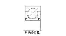
- the maximum contact pressures P 1 and P 2 between the two partial raceway surfaces forming the raceway surface of the inner ring or the outer ring and the rolling elements are used as information including the information related to the contact state.
- these two maximum contact pressure P 1, P 2 and the contact pressure sum P S to represented by a single parameter, the defined formula, calculated from the two maximum contact pressure P 1, P 2, the following equation C f min (P 1 , P 2 ) / max (P 1 , P 2 ) 0 ⁇ C f ⁇ 1 min (P 1 , P 2 ): The smaller value of P 1 and P 2 , max (P 1 , P 2 ): The smaller value of P 1 and P 2 ,
- the sum P S may be calculated rotational torque T for each of the rolling elements.
- the two partial raceway surfaces are raceway surfaces positioned on both sides in the axial direction of the bearing, with the bottom of the raceway surface, that is, the minimum diameter part of the raceway surface of the inner ring or the maximum diameter part of the raceway surface of the outer ring.
- the two partial raceway surfaces form a raceway surface composed of a continuous single curved surface.
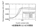
- the rotational torque when the four-point contact rate C f is 0.5 or more is 8 to 10 times the rotational torque T when the four-point contact rate C f is 0.
- the fixed magnification value you set is very good.
- the rotational torque T when the four-point contact rate C f is 0 to less than 0.5 may be a value complemented by a quadratic function of the four-point contact rate C f .
- the torque calculation method is a method executed using a computer, In addition to the individual torque calculation process and the sum calculation process, Calculating the contact pressure for each rolling element,
- the individual torque calculation process is an input process in which a load (Fr (Fx, Fy), Fa, M (Mx, My)) acting on a bearing and a coefficient C determined for each bearing are input and stored in a storage area.
- a load Fr (Fx, Fy), Fa, M (Mx, My)
- the torque calculation method is a method executed using a computer, The individual torque calculation process is determined for each bearing and the maximum contact pressures P 1 and P 2 between the two partial raceway surfaces that form the raceway surface of the inner ring or the outer ring and the rolling elements, and for each bearing.
- the torque calculation method of the present invention is not limited to a single-row four-point contact ball bearing, but may be applied to a double-row four-point contact ball bearing.
- the torque calculation method of the present invention may be applied to a bearing for supporting the blade of a windmill so that the angle can be adjusted, a bearing for a yaw of a windmill, or a bearing for a medical device.
- a torque calculation apparatus is an apparatus for executing the torque calculation method, Contact pressure calculation means for calculating contact pressure for each rolling element; Individual torque calculating means for executing the individual torque calculating process; A sum calculation means for executing the sum calculation process,
- the individual torque calculation means is an input unit for inputting a load acting on the bearing (Fr (Fx, Fy), Fa, M (Mx, My)) and a coefficient C determined for each bearing and storing it in a storage area.
- the maximum contact pressures P 1 and P 2 of the two partial raceway surfaces forming the raceway surface of the inner ring or the outer ring and the rolling elements in each rolling element obtained by the contact pressure calculation means are represented by one parameter.
- a torque calculation apparatus is an apparatus for executing the torque calculation method, Individual torque calculating means for executing the individual torque calculating process; A sum calculation means for executing the sum calculation process, The individual torque calculation means is determined for each of the bearings, the maximum contact pressures P 1 and P 2 between the two partial raceway surfaces forming the raceway surface of the inner ring or the outer ring and the rolling elements, and the bearings.
- a four-point contact rate calculation unit for calculating a four-point contact rate C f which is a ratio of the smaller pressure to the larger pressure determined by Using these contact pressure sum P S , 4-point contact rate C f , and the coefficient C, If 0 ⁇ C f ⁇ 0.5, T (quadratic function of four-point contact rate C f ) ⁇ C ⁇ P S 4 age, If 0.5
- a torque calculation program is a program for causing a computer to execute the torque calculation method, A procedure for calculating the contact pressure for each rolling element; An individual torque calculation procedure for executing the individual torque calculation process; A sum calculation procedure for performing the sum calculation process,
- the individual torque calculation procedure is a procedure for inputting a load (Fr (Fx, Fy), Fa, M (Mx, My)) acting on a bearing and a coefficient C determined for each bearing and storing them in a storage area.
- the maximum contact pressures P 1 and P 2 between the two partial raceway surfaces forming the raceway surface of the inner ring or the outer ring and the rolling elements in each rolling element obtained by the contact pressure calculation procedure are represented by one parameter.
- a torque calculation program is a program for causing a computer to execute the torque calculation method, An individual torque calculation procedure for executing the individual torque calculation process; A sum calculation procedure for performing the sum calculation process, The individual torque calculation procedure is determined for each of the rolling elements, the maximum contact pressures P 1 and P 2 between the two partial raceway surfaces that form the raceway surface of the inner ring or the outer ring and the rolling elements.
- FIG. 1 is a block diagram of a conceptual configuration of a torque calculation device for a four-point contact ball bearing according to an embodiment of the present invention.
- (A) is a flowchart which shows the torque calculation method of the 4-point contact ball bearing which concerns on the embodiment
- (B) is a flowchart which shows the specific content of the separate torque calculation process V1. It is a flowchart including the torque calculation method and a pre-processing process.
- (A) is a flowchart which shows the torque calculation program of the 4-point contact ball bearing which concerns on the embodiment
- (B) is a flowchart which shows a sum total calculation means.
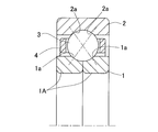
- FIG. 1 shows an example of a four-point contact ball bearing to be calculated.
- This four-point contact ball bearing is an example of a single row bearing, and the groove-shaped partial raceway surfaces 1a, 1a, 2a, 2a of the inner ring 1 and the outer ring 2 are in contact with the rolling element 3 made of balls at four points.
- the two partial raceway surfaces 1a, 1a of the inner ring 1 are adjacent to each other in the axial direction of the bearing to form a single raceway surface that becomes the raceway of the rolling element 3.
- the inner ring 1 is divided into two inner ring divided bodies 1A and 1A in the illustrated example, but may be a single body that is not divided.
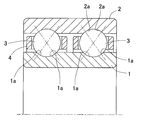
- FIG. 2 shows an example of a double-row four-point contact ball bearing, and both the inner ring 1 and the outer ring 2 are a single body.
- the example of FIG. 2 is also a calculation target of the present invention.
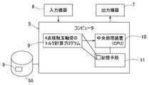
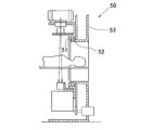
- the torque calculation method for the four-point contact ball bearing is performed by causing the computer 5 shown in FIG. 3 to execute the torque calculation program 9 for the four-point contact ball bearing.
- the computer 5 is a personal computer, has a central processing unit (CPU) 10 and storage means 11 such as a memory, and operates according to a specific operation program.
- the computer 5 is connected to an input device 6 such as a keyboard or a mouse and an output device 7 such as a printer that can be displayed on a screen such as a liquid crystal display device, or is provided as a component of the computer 5.
- the computer 5 is also provided with a recording medium comprising an externally attached or built-in hard disk device 55 (FIG. 3 shows an externally attached form), and stores the torque calculation program 9 for the four-point contact ball bearing.
- the torque calculation program 9 may be stored in a recording medium such as a CD-ROM and read into the computer 5 via the CD-ROM interface of the computer 5.
- the torque calculation program 9 is expanded in the memory 11 when the torque calculation process is executed, and each program command of the program 9 is executed by the central processing unit 10.
- the torque calculation program 9 for the four-point contact ball bearing is read and executed by the computer 5, thereby constituting the torque calculation device for the four-point contact ball bearing in which each function achievement means is shown as a block in FIG. Is done.
- the configuration of the apparatus will be described later.
- the torque calculation program 9 is a program that can be executed by the computer 5 and that causes the computer to calculate the rotational torque that acts between the inner and outer rings of the four-point contact ball bearing.
- the torque calculation program 9 includes the procedure shown in the flowchart of FIG.
- the contact pressure calculation program 8 is also a program that can be executed by the computer 5.
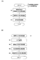
- the torque calculation method for the four-point contact ball bearing includes a contact pressure calculation process V0, an individual torque calculation process V1, and a sum calculation process V2 for each rolling element, as shown in a flowchart in FIG. .
- the individual torque calculation process V1 is a process of calculating the rotational torque T for each rolling element in consideration of the contact state
- the sum total calculation process V2 is the sum of the rotational torques T of the respective rolling elements calculated in the individual torque calculation process V1. In this process, the total sum is obtained as the rotational torque T0 acting between the inner and outer rings.
- the process V0 is a so-called preprocessing process.
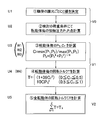
- the specific contents of the individual torque calculation process V1 are shown in a flowchart in FIG. 5B, and the contents of each process are shown in FIG.
- a coefficient C is determined for each bearing to be calculated (V0).
- the coefficient C is a value that differs depending on the specifications of the bearing (the number and dimensions of the rolling elements and the geometric shape of the raceway surface), and is thus determined for each bearing.
- “determined for each bearing” is not necessarily defined for each bearing, but bearings of the same model number, that is, the same shape, size, and material may have the same value and coefficient C.
- the individual torque calculation process V1 includes an input process (W1), a contact pressure sum calculation process (W2), a four-point contact rate calculation process (W3), and a contact ratio-specific torque calculation process (W4).
- the input process (W1) is as described above.
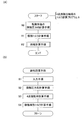
- FIGS. 7A and 7B are flowcharts showing the torque calculation program 9 for the four-point contact ball bearing of FIG.
- This program 9 is a program for executing the torque calculation method described with reference to FIGS. 5A and 5B, and each of the steps R0 to R2 and S1 to S4 is performed in steps V0 to V2, FIG. 5A. This corresponds to W1 to W4 in FIG. 5B, but will be described for the sake of clarity.
- the torque calculation program 9 is a program that can be executed by a computer and that calculates a rotational torque T0 acting between the inner and outer rings of a four-point contact ball bearing, Individual torque calculation procedure (R1) for calculating the rotational torque T for each rolling element, And a sum total calculation procedure (R2) that obtains the sum of the rotational torques T of all the rolling elements and sets the sum as the rotational torque T0 acting between the inner and outer rings.
- the procedure (R0) for calculating the contact pressure for each rolling element may be provided as a part of the torque calculation program, or may be provided separately from the torque calculation program 9.
- the individual torque calculation procedure (R1) includes an input procedure (S1), a contact pressure sum calculation procedure (S2), a four-point contact rate calculation procedure (S3), and a contact rate-specific torque calculation procedure (S4).
- the maximum contact pressures P 1 and P 2 between the two partial raceway surfaces of the inner ring and the rolling elements and the coefficient C determined for each bearing are input in each rolling element.
- This input may be input as a file even if it is input from the input device 3.
- the calculation procedure (R0) may be called and calculated, and the calculation result may be input. In this case, the calculation procedure (R0) is executed after the input procedure (S1).
- the four-point contact rate C f which is the ratio of the smaller pressure to the larger pressure determined by
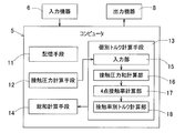
- This torque calculation device is a device that calculates the rotational torque T0 acting between the inner and outer rings of the four-point contact ball bearing, and includes individual torque calculation means 13 that calculates the rotational torque T for each rolling element, and the total rolling elements.
- Sum total calculating means 14 for obtaining a sum of rotational torques T and using the sum as rotational torque T0 acting between the inner and outer rings, and contact pressure calculating means 12 are provided.
- the individual torque calculation means 13 is a means having a processing function performed in the individual torque calculation procedure (R1) in the torque calculation program 9 of FIGS. 7A and 7B, and the sum calculation means 14 is in the torque calculation program 9.
- This means has a processing function in the summation calculation procedure (R2).
- the contact pressure calculation means 12 is a means for calculating the maximum contact pressures P 1 and P 2 between the two partial raceway surfaces of the inner ring and the rolling elements.
- the individual torque calculation means 13 includes an input unit 15, a contact pressure sum calculation unit 16, a four-point contact rate calculation unit 17, and a contact rate-specific torque calculation unit 18.
- These input unit 15, contact pressure sum calculation unit 16, four-point contact rate calculation unit 17, and contact rate-specific torque calculation unit 18 are respectively input procedures (S1) in the torque calculation program 9 in FIG.
- This means has processing functions performed in the contact pressure sum calculation procedure (S2), the four-point contact rate calculation procedure (S3), and the contact rate-specific torque calculation procedure (S4), but will be described for the sake of clarity.
- the input unit 15 stores a storage area when the maximum contact pressures P 1 and P 2 between the two partial raceway surfaces of the inner ring and the rolling elements and the coefficient C determined for each bearing are input to each rolling element. It is means to memorize.
- the input unit 15 may have a function of storing data in a predetermined storage area when data necessary for the calculation of the maximum contact pressures P 1 and P 2 and the coefficient C are input.
- the total sum calculation means 14 calculates the rotational torque ⁇ T of all the rolling elements using the equation (1) described in step (U5) of FIG.
- the only factor considered as bearing torque was friction due to slippage in the contact area.
- this friction coefficient was assumed to be boundary lubrication, and was adopted as a function of only the sliding speed.
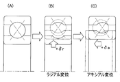
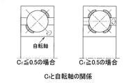
- a variable representing the degree of transition from 4-point contact to 2-point contact is defined.
- the maximum contact pressures of the two partial raceway surfaces of the inner ring and the rolling elements are defined as P 1 and P 2
- the ratio of the small pressure to the large pressure is defined as the four-point contact rate Cf as shown in the following equation.
- a contact pressure sum Ps for representing the contact pressure of P 1 and P 2 with one parameter is defined as follows.
- P S (P 1 4 + P 2 4 ) 1/4 This is because the fourth power of the contact pressure is considered to be proportional to the rotational torque from the following relationship.
- Pc ⁇ Q 1/3 Heltz point contact theory
- T Q 1.33
- T rotational torque
- C is a bearing specification (geometric shape of rolling elements and raceways), that is, a coefficient determined for each bearing.
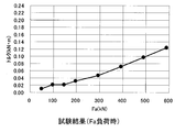
- FIG. 13 Comparison between test results and calculation results
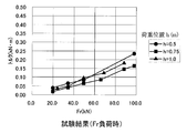
- FIG. 14 Comparison between test results and calculation results
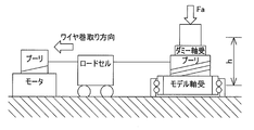
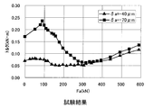
- the test results are shown in FIG. 13 (at the time of Fa load) and FIG. 14 (at the time of Fr + M load).
- the dummy bearings of the testing machines shown in FIGS. 8A and 8B are separately subjected to a torque test, and the rotational torque of the model bearing is obtained by subtracting from the actual measurement value.
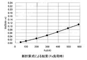
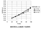
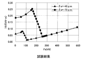
- FIG. 19 shows the test results
- FIG. 20 shows the calculation results.
- the tendency for torque to increase once, then decrease and then increase again due to an increase in Fa was in good agreement between the test and the formula. This is because greater than 0.5 states the four-point contact ratio C f, but also increases the torque with an increase in contact pressure, C f is bearing friction coefficient is reduced by the change of the rotation axis below 0.5 Thus, the bearing torque is reduced.
- FIG. 21 shows an example of a wind turbine for wind power generation using a four-point contact ball bearing to be calculated.
- the wind turbine 31 is provided with a nacelle 33 on a support base 32 so as to be horizontally rotatable via a bearing 42 for yaw, and a main shaft 35 is rotatably supported in a casing 34 of the nacelle 33.
- a blade 36 which is a swirl blade, is attached to one end of the main shaft 35 protruding from the casing 34 via a bearing 41 so that the angle can be changed.
- the other end of the main shaft 35 is connected to a speed increaser 37, and an output shaft 38 of the speed increaser 37 is coupled to the rotor shaft of the generator 39.
- yaw bearing 42 and the bearing 41 for changing the angle of the blade 36 a four-point contact ball bearing serving as a slewing bearing (that is, a turntable bearing) is used.
- These bearings 41 and 42 are targets of torque calculation of this embodiment.
- FIG. 22 shows an example of a CT scanner 50 that is a medical device, and there is a gantry as an inspection unit, and an X-ray tube, a detector, and the like for taking an image are installed in the rotating portion 51.
- the rotating portion is rotatably supported by the frame 53 via a bearing 52.
- the CT scanner / gantry bearing 52 is a four-point contact ball bearing which is a slewing bearing. This bearing 52 is an object of torque calculation of this embodiment.
- a computer-readable recording medium is a computer-readable recording medium that records a program that causes a computer to execute the torque calculation method of the present invention.
- the individual torque calculation procedure is a procedure for inputting a load (Fr (Fx, Fy), Fa, M (Mx, My)) acting on a bearing and a coefficient C determined for each bearing and storing them in a storage area.
- a computer-readable recording medium is a computer-readable recording medium recording a program that causes a computer to execute the torque calculation method of the present invention.
- the maximum contact pressures P 1 and P 2 between the two partial raceway surfaces of the inner ring or the outer ring and the rolling elements in each rolling element and the coefficient C determined for each bearing are input.
Landscapes
- Engineering & Computer Science (AREA)
- General Engineering & Computer Science (AREA)
- Mechanical Engineering (AREA)
- Physics & Mathematics (AREA)
- General Physics & Mathematics (AREA)
- Rolling Contact Bearings (AREA)
- Testing Of Devices, Machine Parts, Or Other Structures Thereof (AREA)
- Force Measurement Appropriate To Specific Purposes (AREA)
Priority Applications (5)
| Application Number | Priority Date | Filing Date | Title |
|---|---|---|---|
| EP11734584.3A EP2527671A4 (en) | 2010-01-20 | 2011-01-14 | TORQUE COMPENSATION PROCEDURE FOR A FOUR-POINT CONTACT BALL BEARING AND CALCULATION DEVICE AND CALCULATION PROGRAM THEREFOR |
| KR1020127018168A KR101858037B1 (ko) | 2010-01-20 | 2011-01-14 | 4점 접촉 볼베어링의 토크 계산 방법, 계산 장치 및 계산 프로그램 |
| IN6585DEN2012 IN2012DN06585A (enExample) | 2010-01-20 | 2011-01-14 | |
| CN201180006629.1A CN102725545B (zh) | 2010-01-20 | 2011-01-14 | 四点接触滚珠轴承的力矩计算方法、计算装置与实施方法 |
| US13/552,822 US9002662B2 (en) | 2010-01-20 | 2012-07-19 | Torque calculation method, calculation device, and calculation program for four-point contact ball bearing |
Applications Claiming Priority (2)
| Application Number | Priority Date | Filing Date | Title |
|---|---|---|---|
| JP2010010259A JP5506420B2 (ja) | 2010-01-20 | 2010-01-20 | 4点接触玉軸受のトルク計算方法・計算装置・および計算プログラム |
| JP2010-010259 | 2010-01-20 |
Related Child Applications (1)
| Application Number | Title | Priority Date | Filing Date |
|---|---|---|---|
| US13/552,822 Continuation US9002662B2 (en) | 2010-01-20 | 2012-07-19 | Torque calculation method, calculation device, and calculation program for four-point contact ball bearing |
Publications (1)
| Publication Number | Publication Date |
|---|---|
| WO2011089977A1 true WO2011089977A1 (ja) | 2011-07-28 |
Family
ID=44306781
Family Applications (1)
| Application Number | Title | Priority Date | Filing Date |
|---|---|---|---|
| PCT/JP2011/050525 Ceased WO2011089977A1 (ja) | 2010-01-20 | 2011-01-14 | 4点接触玉軸受のトルク計算方法・計算装置・および計算プログラム |
Country Status (7)
| Country | Link |
|---|---|
| US (1) | US9002662B2 (enExample) |
| EP (1) | EP2527671A4 (enExample) |
| JP (1) | JP5506420B2 (enExample) |
| KR (1) | KR101858037B1 (enExample) |
| CN (1) | CN102725545B (enExample) |
| IN (1) | IN2012DN06585A (enExample) |
| WO (1) | WO2011089977A1 (enExample) |
Cited By (1)
| Publication number | Priority date | Publication date | Assignee | Title |
|---|---|---|---|---|
| CN106104249A (zh) * | 2014-03-22 | 2016-11-09 | Ntn株式会社 | 薄壁大型轴承的试验装置 |
Families Citing this family (10)
| Publication number | Priority date | Publication date | Assignee | Title |
|---|---|---|---|---|
| CN103174741B (zh) * | 2013-03-20 | 2015-06-03 | 天津职业技术师范大学 | 一种四点接触球轴承原始接触角的设计方法 |
| JP6238796B2 (ja) * | 2014-03-07 | 2017-11-29 | Ntn株式会社 | 計算方法、計算装置および計算システム |
| JP6290342B1 (ja) * | 2016-09-07 | 2018-03-07 | Ntn株式会社 | 左右輪駆動装置の制御装置 |
| JP2018204681A (ja) | 2017-06-02 | 2018-12-27 | 株式会社不二越 | 複列4点接触玉軸受 |
| CN107590356B (zh) * | 2017-10-31 | 2020-04-28 | 国电联合动力技术有限公司 | 一种风力发电机组主轴轴承自动选型方法及存储设备 |
| JP6806827B2 (ja) * | 2019-03-04 | 2021-01-06 | Ntn株式会社 | 車輪用軸受装置の予圧検査方法及び組立方法 |
| DE102019115140A1 (de) * | 2019-06-05 | 2020-12-10 | Schaeffler Technologies AG & Co. KG | Wälzlager |
| CN110823323B (zh) * | 2019-09-17 | 2021-01-19 | 中国航发沈阳发动机研究所 | 一种涡轮转子叶片水流量测量值的修正方法 |
| CN111209686B (zh) * | 2020-01-16 | 2024-04-19 | 重庆大学 | 基于复合形法的滚动轴承多体润滑性能求解方法 |
| CN112283242A (zh) * | 2020-09-30 | 2021-01-29 | 人本股份有限公司 | 轮毂单元轴承 |
Citations (3)
| Publication number | Priority date | Publication date | Assignee | Title |
|---|---|---|---|---|
| JP2000162092A (ja) * | 1998-11-27 | 2000-06-16 | Nsk Ltd | 転がり軸受用動トルク測定装置 |
| JP2003172341A (ja) * | 2001-09-28 | 2003-06-20 | Nsk Ltd | ボールねじ支持用多点接触玉軸受 |
| JP2006177774A (ja) * | 2004-12-22 | 2006-07-06 | Nsk Ltd | 転がり軸受の動トルク測定方法と測定装置及び転がり軸受の異常検知方法及び異常検知装置 |
Family Cites Families (7)
| Publication number | Priority date | Publication date | Assignee | Title |
|---|---|---|---|---|
| DE3244258A1 (de) | 1982-11-30 | 1984-05-30 | Fa. Carl Zeiss, 7920 Heidenheim | Waelzlager fuer radialbewegungen |
| JP3405235B2 (ja) * | 1998-11-24 | 2003-05-12 | 日本精工株式会社 | ラジアル転がり軸受用回転精度及び動トルク測定装置 |
| WO2005110032A2 (en) * | 2004-05-07 | 2005-11-24 | The Timken Company | Locating bearing assembly for wind turbine gearbox shaft |
| JP2006316915A (ja) * | 2005-05-13 | 2006-11-24 | Nsk Ltd | 軸受装置 |
| CN101373495B (zh) | 2007-08-24 | 2010-09-29 | 西门子公司 | 使用寿命终点判定及当前历史使用寿命估计的方法和系统 |
| JP4882023B2 (ja) * | 2008-03-19 | 2012-02-22 | 平田機工株式会社 | ワーク検査搬送装置 |
| JP5018667B2 (ja) | 2008-06-20 | 2012-09-05 | 株式会社ジェイテクト | 回転トルク検出装置 |
-
2010
- 2010-01-20 JP JP2010010259A patent/JP5506420B2/ja not_active Expired - Fee Related
-
2011
- 2011-01-14 CN CN201180006629.1A patent/CN102725545B/zh not_active Expired - Fee Related
- 2011-01-14 KR KR1020127018168A patent/KR101858037B1/ko not_active Expired - Fee Related
- 2011-01-14 EP EP11734584.3A patent/EP2527671A4/en not_active Withdrawn
- 2011-01-14 IN IN6585DEN2012 patent/IN2012DN06585A/en unknown
- 2011-01-14 WO PCT/JP2011/050525 patent/WO2011089977A1/ja not_active Ceased
-
2012
- 2012-07-19 US US13/552,822 patent/US9002662B2/en not_active Expired - Fee Related
Patent Citations (3)
| Publication number | Priority date | Publication date | Assignee | Title |
|---|---|---|---|---|
| JP2000162092A (ja) * | 1998-11-27 | 2000-06-16 | Nsk Ltd | 転がり軸受用動トルク測定装置 |
| JP2003172341A (ja) * | 2001-09-28 | 2003-06-20 | Nsk Ltd | ボールねじ支持用多点接触玉軸受 |
| JP2006177774A (ja) * | 2004-12-22 | 2006-07-06 | Nsk Ltd | 転がり軸受の動トルク測定方法と測定装置及び転がり軸受の異常検知方法及び異常検知装置 |
Non-Patent Citations (1)
| Title |
|---|
| See also references of EP2527671A4 * |
Cited By (1)
| Publication number | Priority date | Publication date | Assignee | Title |
|---|---|---|---|---|
| CN106104249A (zh) * | 2014-03-22 | 2016-11-09 | Ntn株式会社 | 薄壁大型轴承的试验装置 |
Also Published As
| Publication number | Publication date |
|---|---|
| IN2012DN06585A (enExample) | 2015-10-23 |
| JP5506420B2 (ja) | 2014-05-28 |
| KR101858037B1 (ko) | 2018-05-15 |
| US9002662B2 (en) | 2015-04-07 |
| EP2527671A1 (en) | 2012-11-28 |
| JP2011149471A (ja) | 2011-08-04 |
| CN102725545A (zh) | 2012-10-10 |
| US20120283965A1 (en) | 2012-11-08 |
| KR20120113227A (ko) | 2012-10-12 |
| CN102725545B (zh) | 2015-03-25 |
| EP2527671A4 (en) | 2016-06-22 |
Similar Documents
| Publication | Publication Date | Title |
|---|---|---|
| JP5506420B2 (ja) | 4点接触玉軸受のトルク計算方法・計算装置・および計算プログラム | |
| CN104884926B (zh) | 轴承装置振动分析方法、轴承装置振动分析装置和滚动轴承状态监视装置 | |
| Leblanc et al. | Ball motion and sliding friction in a four-contact-point ball bearing | |
| Lacroix et al. | Four-point contact ball bearing model with deformable rings | |
| Xu et al. | Contact characteristics analysis of deep groove ball bearings under combined angular misalignments and external loads | |
| Houpert | An enhanced study of the load–displacement relationships for rolling element bearings | |
| Medina et al. | Regimes of contact in spline couplings | |
| Halminen et al. | A touchdown bearing with surface waviness: Friction loss analysis | |
| Heras et al. | Friction torque in four-point contact slewing bearings: Applicability and limitations of current analytical formulations | |
| Liu et al. | An analysis of the load distribution characteristics of a cylindrical roller bearing including the component deformation and waviness | |
| Zheng et al. | An enhanced estimation on heat generation of angular contact ball bearings with vibration effect | |
| Wang et al. | Structural optimization of the main bearing in a tunnel boring machine considering clearance | |
| Lin et al. | Dynamic characteristics of motorized spindle with tandem duplex angular contact ball bearings | |
| Cheng et al. | Effect of boundary position and defect shape on the mechanical properties of ball bearings | |
| JP2019190943A (ja) | 転がり軸受疲労状態予測システム | |
| Ashtekar et al. | Experimental and analytical investigation of high speed turbocharger ball bearings | |
| Silva Barbosa et al. | Kriging approach dedicated to represent hydrodynamic bearings | |
| Yin et al. | Analysis of non-uniform abrasion evolution for cylindrical roller bearings | |
| Heydari et al. | The influences of stagger and pretwist angles of blades on coupling vibration in shaft-disk-blade systems | |
| Rimpel et al. | A rotordynamic, thermal, and thrust load performance gas bearing test rig and test results for tilting pad journal bearings and spiral groove thrust bearings | |
| Boedo | A hybrid mobility solution approach for dynamically loaded misaligned journal bearings | |
| Kochurov et al. | Ball Bearing Dynamic Stiffness Prediction Considering an Uncertain Position of Rolling Elements | |
| Ma et al. | Dimensional discussion of traction force vector on ball/raceway interface and study of bearing dynamic behavior | |
| Liu et al. | Study on internal load distribution of deep groove ball bearings considering raceway surface waviness | |
| Li et al. | Study of Rotor Dynamics of Micro Gas Turbine Supported by Air Foil Bearings |
Legal Events
| Date | Code | Title | Description |
|---|---|---|---|
| WWE | Wipo information: entry into national phase |
Ref document number: 201180006629.1 Country of ref document: CN |
|
| 121 | Ep: the epo has been informed by wipo that ep was designated in this application |
Ref document number: 11734584 Country of ref document: EP Kind code of ref document: A1 |
|
| ENP | Entry into the national phase |
Ref document number: 20127018168 Country of ref document: KR Kind code of ref document: A |
|
| NENP | Non-entry into the national phase |
Ref country code: DE |
|
| WWE | Wipo information: entry into national phase |
Ref document number: 6585/DELNP/2012 Country of ref document: IN |
|
| WWE | Wipo information: entry into national phase |
Ref document number: 2011734584 Country of ref document: EP |