WO2011080893A1 - 電子写真用ベルト及び電子写真装置 - Google Patents
電子写真用ベルト及び電子写真装置 Download PDFInfo
- Publication number
- WO2011080893A1 WO2011080893A1 PCT/JP2010/007403 JP2010007403W WO2011080893A1 WO 2011080893 A1 WO2011080893 A1 WO 2011080893A1 JP 2010007403 W JP2010007403 W JP 2010007403W WO 2011080893 A1 WO2011080893 A1 WO 2011080893A1
- Authority
- WO
- WIPO (PCT)
- Prior art keywords
- belt
- electrophotographic
- electrophotographic belt
- group
- silicone
- Prior art date
- Legal status (The legal status is an assumption and is not a legal conclusion. Google has not performed a legal analysis and makes no representation as to the accuracy of the status listed.)
- Ceased
Links
- 0 CCCCC(C)(*C=C)N* Chemical compound CCCCC(C)(*C=C)N* 0.000 description 2
Images

Classifications
-
- G—PHYSICS
- G03—PHOTOGRAPHY; CINEMATOGRAPHY; ANALOGOUS TECHNIQUES USING WAVES OTHER THAN OPTICAL WAVES; ELECTROGRAPHY; HOLOGRAPHY
- G03G—ELECTROGRAPHY; ELECTROPHOTOGRAPHY; MAGNETOGRAPHY
- G03G15/00—Apparatus for electrographic processes using a charge pattern
- G03G15/14—Apparatus for electrographic processes using a charge pattern for transferring a pattern to a second base
- G03G15/16—Apparatus for electrographic processes using a charge pattern for transferring a pattern to a second base of a toner pattern, e.g. a powder pattern, e.g. magnetic transfer
-
- C—CHEMISTRY; METALLURGY
- C08—ORGANIC MACROMOLECULAR COMPOUNDS; THEIR PREPARATION OR CHEMICAL WORKING-UP; COMPOSITIONS BASED THEREON
- C08L—COMPOSITIONS OF MACROMOLECULAR COMPOUNDS
- C08L67/00—Compositions of polyesters obtained by reactions forming a carboxylic ester link in the main chain; Compositions of derivatives of such polymers
- C08L67/02—Polyesters derived from dicarboxylic acids and dihydroxy compounds
-
- C—CHEMISTRY; METALLURGY
- C08—ORGANIC MACROMOLECULAR COMPOUNDS; THEIR PREPARATION OR CHEMICAL WORKING-UP; COMPOSITIONS BASED THEREON
- C08L—COMPOSITIONS OF MACROMOLECULAR COMPOUNDS
- C08L83/00—Compositions of macromolecular compounds obtained by reactions forming in the main chain of the macromolecule a linkage containing silicon with or without sulfur, nitrogen, oxygen or carbon only; Compositions of derivatives of such polymers
- C08L83/14—Compositions of macromolecular compounds obtained by reactions forming in the main chain of the macromolecule a linkage containing silicon with or without sulfur, nitrogen, oxygen or carbon only; Compositions of derivatives of such polymers in which at least two but not all the silicon atoms are connected by linkages other than oxygen atoms
-
- C—CHEMISTRY; METALLURGY
- C08—ORGANIC MACROMOLECULAR COMPOUNDS; THEIR PREPARATION OR CHEMICAL WORKING-UP; COMPOSITIONS BASED THEREON
- C08L—COMPOSITIONS OF MACROMOLECULAR COMPOUNDS
- C08L83/00—Compositions of macromolecular compounds obtained by reactions forming in the main chain of the macromolecule a linkage containing silicon with or without sulfur, nitrogen, oxygen or carbon only; Compositions of derivatives of such polymers
- C08L83/16—Compositions of macromolecular compounds obtained by reactions forming in the main chain of the macromolecule a linkage containing silicon with or without sulfur, nitrogen, oxygen or carbon only; Compositions of derivatives of such polymers in which all the silicon atoms are connected by linkages other than oxygen atoms
-
- G—PHYSICS
- G03—PHOTOGRAPHY; CINEMATOGRAPHY; ANALOGOUS TECHNIQUES USING WAVES OTHER THAN OPTICAL WAVES; ELECTROGRAPHY; HOLOGRAPHY
- G03G—ELECTROGRAPHY; ELECTROPHOTOGRAPHY; MAGNETOGRAPHY
- G03G15/00—Apparatus for electrographic processes using a charge pattern
- G03G15/14—Apparatus for electrographic processes using a charge pattern for transferring a pattern to a second base
- G03G15/16—Apparatus for electrographic processes using a charge pattern for transferring a pattern to a second base of a toner pattern, e.g. a powder pattern, e.g. magnetic transfer
- G03G15/1605—Apparatus for electrographic processes using a charge pattern for transferring a pattern to a second base of a toner pattern, e.g. a powder pattern, e.g. magnetic transfer using at least one intermediate support
- G03G15/162—Apparatus for electrographic processes using a charge pattern for transferring a pattern to a second base of a toner pattern, e.g. a powder pattern, e.g. magnetic transfer using at least one intermediate support details of the the intermediate support, e.g. chemical composition
-
- G—PHYSICS
- G03—PHOTOGRAPHY; CINEMATOGRAPHY; ANALOGOUS TECHNIQUES USING WAVES OTHER THAN OPTICAL WAVES; ELECTROGRAPHY; HOLOGRAPHY
- G03G—ELECTROGRAPHY; ELECTROPHOTOGRAPHY; MAGNETOGRAPHY
- G03G15/00—Apparatus for electrographic processes using a charge pattern
- G03G15/14—Apparatus for electrographic processes using a charge pattern for transferring a pattern to a second base
- G03G15/16—Apparatus for electrographic processes using a charge pattern for transferring a pattern to a second base of a toner pattern, e.g. a powder pattern, e.g. magnetic transfer
- G03G15/1665—Apparatus for electrographic processes using a charge pattern for transferring a pattern to a second base of a toner pattern, e.g. a powder pattern, e.g. magnetic transfer by introducing the second base in the nip formed by the recording member and at least one transfer member, e.g. in combination with bias or heat
- G03G15/167—Apparatus for electrographic processes using a charge pattern for transferring a pattern to a second base of a toner pattern, e.g. a powder pattern, e.g. magnetic transfer by introducing the second base in the nip formed by the recording member and at least one transfer member, e.g. in combination with bias or heat at least one of the recording member or the transfer member being rotatable during the transfer
- G03G15/1685—Structure, details of the transfer member, e.g. chemical composition
-
- C—CHEMISTRY; METALLURGY
- C08—ORGANIC MACROMOLECULAR COMPOUNDS; THEIR PREPARATION OR CHEMICAL WORKING-UP; COMPOSITIONS BASED THEREON
- C08G—MACROMOLECULAR COMPOUNDS OBTAINED OTHERWISE THAN BY REACTIONS ONLY INVOLVING UNSATURATED CARBON-TO-CARBON BONDS
- C08G77/00—Macromolecular compounds obtained by reactions forming a linkage containing silicon with or without sulfur, nitrogen, oxygen or carbon in the main chain of the macromolecule
- C08G77/04—Polysiloxanes
- C08G77/22—Polysiloxanes containing silicon bound to organic groups containing atoms other than carbon, hydrogen and oxygen
- C08G77/26—Polysiloxanes containing silicon bound to organic groups containing atoms other than carbon, hydrogen and oxygen nitrogen-containing groups
-
- C—CHEMISTRY; METALLURGY
- C08—ORGANIC MACROMOLECULAR COMPOUNDS; THEIR PREPARATION OR CHEMICAL WORKING-UP; COMPOSITIONS BASED THEREON
- C08G—MACROMOLECULAR COMPOUNDS OBTAINED OTHERWISE THAN BY REACTIONS ONLY INVOLVING UNSATURATED CARBON-TO-CARBON BONDS
- C08G77/00—Macromolecular compounds obtained by reactions forming a linkage containing silicon with or without sulfur, nitrogen, oxygen or carbon in the main chain of the macromolecule
- C08G77/48—Macromolecular compounds obtained by reactions forming a linkage containing silicon with or without sulfur, nitrogen, oxygen or carbon in the main chain of the macromolecule in which at least two but not all the silicon atoms are connected by linkages other than oxygen atoms
- C08G77/50—Macromolecular compounds obtained by reactions forming a linkage containing silicon with or without sulfur, nitrogen, oxygen or carbon in the main chain of the macromolecule in which at least two but not all the silicon atoms are connected by linkages other than oxygen atoms by carbon linkages
-
- Y—GENERAL TAGGING OF NEW TECHNOLOGICAL DEVELOPMENTS; GENERAL TAGGING OF CROSS-SECTIONAL TECHNOLOGIES SPANNING OVER SEVERAL SECTIONS OF THE IPC; TECHNICAL SUBJECTS COVERED BY FORMER USPC CROSS-REFERENCE ART COLLECTIONS [XRACs] AND DIGESTS
- Y10—TECHNICAL SUBJECTS COVERED BY FORMER USPC
- Y10T—TECHNICAL SUBJECTS COVERED BY FORMER US CLASSIFICATION
- Y10T428/00—Stock material or miscellaneous articles
- Y10T428/31504—Composite [nonstructural laminate]
- Y10T428/31786—Of polyester [e.g., alkyd, etc.]
Definitions
- the present invention relates to an electrophotographic belt and an electrophotographic apparatus.
- the object of the invention described in Patent Document 1 is to provide an intermediate transfer belt that has excellent surface filming resistance and transferability over a long period of time and suppresses the abrasion of a cleaning blade. Further, it is described that such an object can be achieved by a transfer belt comprising a matrix resin and a chain silicone, wherein the silicone content in the matrix resin is 0.5 to 10% by weight.
- a transfer belt comprising a matrix resin and a chain silicone, wherein the silicone content in the matrix resin is 0.5 to 10% by weight.
- chain organopolysiloxane is cited.
- the inventors of the present invention have examined the transfer belt according to the invention described in Patent Document 1, and have found the following problems. That is, in order to improve the lubricity of the surface of the transfer belt uniformly, it is necessary to knead the matrix resin and silicone and uniformly disperse the silicone in the matrix resin.
- an object of the present invention is to provide an electrophotographic belt which contains a high melting point polyalkylene terephthalate or polyalkylene naphthalate as a matrix resin, and has excellent surface releasability, lubricity and secondary transferability. There is to do.
- Another object of the present invention is to provide an electrophotographic image apparatus that includes an intermediate transfer belt and can stably form high-quality electrophotographic images.
- the belt for electrophotography comprises (A) at least one selected from polyalkylene terephthalate and polyalkylene naphthalate, and (B) a thermoplastic silicone elastomer having a repeating unit represented by the following formula (I). Contains:
- R 1 to R 4 each independently represents a monovalent hydrocarbon group having 1 to 20 carbon atoms.
- X represents a divalent hydrocarbon group having 2 to 20 carbon atoms. Represents an integer of 2 to 10, and b represents an integer of 1 to 4000).
- the electrophotographic apparatus according to the present invention is characterized in that the electrophotographic belt is provided as an intermediate transfer belt.
- an electrophotographic belt containing at least one selected from polyalkylene terephthalate and polyalkylene naphthalate having a high melting point as a matrix resin.
- the electrophotographic belt according to the present invention includes the following (A) and (B): (A) at least one selected from polyalkylene terephthalate and polyalkylene naphthalate; (B) Thermoplastic silicone elastomer.
- the thermoplastic silicone elastomer (B) has a repeating unit represented by the following structural formula (I). Structural formula (I)
- R 1 to R 4 each independently represents a monovalent hydrocarbon group having 1 to 20 carbon atoms.
- X represents a divalent hydrocarbon group having 2 to 20 carbon atoms.
- A represents an integer of 2 to 10
- b represents an integer of 1 to 4000.
- Polyethylene naphthalate can be particularly preferably used as the polyalkylene naphthalate.
- polyethylene terephthalate can be suitably used.
- thermoplastic silicone elastomer according to component (B) has a repeating unit represented by the formula (I).
- the thermoplastic silicone elastomer according to the present invention includes a polydimethylsiloxane segment having a siloxane bond in a molecular skeleton and a crystalline segment having a urea bond (—NH—CO—NH—). And have.
- R 1 to R 4 each independently represents a monovalent hydrocarbon group of 1 to 20. Specific examples are listed below. Methyl group, ethyl group, n-propyl group, isopropyl group, n-butyl group, isobutyl group, n-pentyl group, n-hexyl group, n-heptyl group, n-octyl group, isooctyl group, vinyl group, phenyl group 1-phenylethyl group, 2-phenylethyl group, cyclopentyl group, cyclohexyl group, norbornyl group.
- the hydrocarbon group in this case also includes fluoroalkyl such as 3,3,3-trifluoropropyl group.
- X represents a divalent hydrocarbon group having 2 to 20 carbon atoms.
- Examples of X include a linear alkylene group, a cyclic alkylene group, an aralkylene group, and the like, and specific examples include a 4,4′-dicyclohexylmethyl group represented by the following structural formula (II). it can.
- additives such as a conductive agent, a compatibilizer, a dispersant, a colorant, and various fillers can be used in accordance with the performance required for an electrophotographic belt.
- the reason why the additives are dispersed in the belt is to improve the mechanical properties, electrical properties, chemical properties, and the like of the belt. Specifically, the elastic modulus of the belt is improved, it can be driven without deformation even after long-term use, the transfer characteristics can be improved by controlling the charging characteristics of the surface, and fluctuations due to various environments can be reduced. This is to enable stable use.
- thermoplastic silicone elastomer according to the component (B) is selected as the additive dispersed in the component (A) in the present invention.
- the electrophotographic belt is used in a state where it is stretched with a predetermined tension in the electrophotographic apparatus.
- the surface comes into contact with toner, its external additives, paper, etc. May cause scratches, and toner or toner external additives may adhere. These may affect the quality of the electrophotographic image.
- it has been attempted to improve the lubricity of the surface of the electrophotographic belt.
- a technique for improving the lubricity of the belt surface a method of melting and kneading at a high temperature to disperse silicone in a matrix resin is known. *
- Silicone types include silicone oil, silicone rubber, and thermoplastic silicone elastomer.
- Silicone oil volatilizes during melt kneading with the matrix resin at a high temperature, and it is difficult to control the content in the final belt.
- a matrix resin kneaded with silicone oil may have poor moldability.
- silicone rubber crosslinks into a lump during melt-kneading with the matrix resin, making it difficult to disperse in the matrix resin. Therefore, it is difficult to sufficiently improve the lubricity of the belt surface, and a convex portion derived from an aggregate of silicone rubber may be formed on the surface of the belt.
- the secondary transfer property may be lowered.
- thermoplastic silicone elastomer according to the present invention is excellent in lubricity, water resistance, heat resistance, and electrical properties, such as silicone properties and rubber elasticity properties as a thermoplastic elastomer. Have both.
- the characteristics of silicone vary greatly depending on the type of main chain, side chain, and terminal bond in the molecular chain other than the siloxane bond.
- Typical examples of the bond include an ether bond, an ester bond, an amide bond, a urethane bond, and a urea bond.
- thermoplastic silicone elastomer is a polar group and is very easy to hydrogen bond. Therefore, it is easy to mix with other polar resins. Silicones are also easily bonded by hydrogen bonding. As a result, the thermoplastic silicone elastomer having a urea bond is greatly different from silicone rubber in the type of crosslinking.
- Crosslinking of silicone rubber has a very high bonding force because the polymers are linked by covalent bonds. Therefore, when melt-kneading is performed at a high temperature, the applied heat energy is consumed for cutting other than the cross-linked portion. As a result, the molecular weight of the silicone rubber decreases, and the silicone rubber is decomposed.
- thermoplastic silicone elastomer containing a urea bond is considered to be crosslinked by hydrogen bonds.
- the cross-linking force due to hydrogen bonds is weaker than the cross-linking force due to covalent bonds. Since hydrogen bonding is a non-covalent intermolecular dynamic interaction, it is considered as a kind of physical cross-linking, and this physical cross-linking is easily broken by applying thermal energy.
- thermoplastic silicone elastomer crosslinked by hydrogen bonds the thermal energy is consumed for breaking the hydrogen bonds, so that the silicone molecular chain is not easily broken and the molecular weight is not easily lowered. That is, the thermoplastic silicone elastomer containing a urea bond is not easily decomposed even at a high temperature. That is, it has excellent heat resistance. Therefore, the thermoplastic silicone elastomer according to the present invention can be melt kneaded at a high temperature together with a high melting point matrix resin.
- thermoplastic silicone elastomer of the present invention can be dispersed in the matrix resin without deteriorating the properties of the silicone.
- Conventional silicone rubber has poor dispersibility in matrix resin due to cross-linking and low molecular weight at the time of melt-kneading, and surface smoothness may be lowered, or lubricity may not be sufficiently exhibited. This is because the characteristics of the silicone rubber change due to the cross-linking, or as a result of the lump of the silicone rubber projecting to the belt surface, the surface unevenness increases. Further, the lump of silicone rubber present in the belt causes a decrease in adhesion with the matrix resin phase, which also decreases the mechanical strength of the belt and deteriorates the durability.
- thermoplastic silicone elastomer is uniformly dispersed. Accordingly, the surface has excellent lubricity and surface smoothness. Further, since it is finely compatible and dispersed in the matrix resin, the adhesiveness with the matrix resin phase is excellent, the mechanical strength is high, and the durability is excellent.
- the surface smoothness of the belt is also an important factor for secondary transferability in electrophotography. If the surface smoothness is poor, the image quality of the initial image is significantly deteriorated. This is because if the unevenness on the belt is large, the toner is not stably held, and minute resistance unevenness occurs due to the difference in the thickness of the toner layer, or the electrostatic adsorption force between the belt and the toner can be different. If the difference in electrostatic attraction force is large, it becomes difficult to control the voltage for efficient secondary transfer, which causes a decrease in secondary transferability.
- the belt in which the thermoplastic silicone elastomer of the present invention is dispersed is excellent in surface smoothness, the toner is stably held on the belt. Furthermore, since the electrostatic attraction force for the toner held on the belt is applied uniformly, voltage control is easy and secondary transferability is improved. Further, since the crosslinking force of the urea group in the silicone molecular chain is very small, the increase in resistance due to crosslinking can be mitigated, and the decrease in transferability due to the minute resistance unevenness of the belt can be suppressed. Therefore, a belt in which a thermoplastic elastomer containing a urea bond is dispersed is very effective in improving secondary transferability.
- thermoplastic silicone elastomer of the present invention also has characteristics as a thermoplastic elastomer. Since the thermoplastic elastomer has rubber elasticity, it is particularly useful for adjusting the elastic modulus in terms of improving the mechanical properties of the belt, and is characterized in that the belt can be adjusted to a strength with less winding wrinkles even if the belt is used for a long period.
- the winding gusset is permanent distortion generated in a portion of the belt wound around the belt when the belt stretched between the driving roller and the driven roller is left for a certain period of time. If this permanent distortion is large, the internal stress of the belt may be different, causing breakage, or retransfer of toner at the secondary transfer portion, which may cause a decrease in secondary transferability.
- thermoplastic silicone elastomer of the present invention is preferably contained in the matrix resin in an amount of 0.1 to 10% by mass.
- content in the matrix resin is within the above range, the effect of improving the lubricity of the surface can be more reliably exhibited without significantly affecting the elastic modulus of the electrophotographic belt.
- thermoplastic silicone elastomer As described above, with the thermoplastic silicone elastomer according to the present invention, a belt excellent in moldability and mechanical properties can be produced even if a step of melt kneading at a high temperature is included.
- thermoplastic silicone elastomer of the present invention can be compatible with the matrix resin due to the presence of urea bonds contained in the molecular chain, and can be finely dispersed in the matrix resin. Therefore, the produced belt is very excellent in surface smoothness and secondary transferability.
- Examples of the method for forming a seamless electrophotographic belt according to the present invention include centrifugal molding, tube extrusion, inflation molding, extrusion molding, cylindrical extrusion molding, and blow molding.
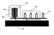
- blow molding shown in FIG. 2 is particularly preferable.
- 101 is a test tube-shaped preform
- 102 is a heating furnace
- 103 is a blow mold
- 104 is a drawing rod
- 105 is a blow-molded product
- 106 is an air inlet.
- blow molding The characteristics of blow molding are that molecular orientation occurs by stretching, the mechanical strength of the belt is improved, and a belt having excellent molding reproducibility and small film thickness unevenness can be molded. In addition, it can be molded at a high speed, and recycled products can be reused, thereby reducing costs.
- the matrix resin dried at 140 ° C. for 6 hours or more and the thermoplastic silicone elastomer are melt-kneaded at 260 ° C. with a twin screw extruder. Each uniformly mixed component is extruded as a strand having a diameter of about 2 mm, solidified with cold water, and cut to produce a pellet. If the resin contains moisture, the moldability deteriorates, so the prepared pellets are dried at 140 ° C. for 6 hours or more.
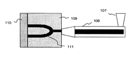
- the dried pellets are put into an injection molding apparatus as shown in FIG. 3, and injection molding is performed by adjusting the temperature to 285 ° C. to produce a preform as shown in FIG.
- 107 is a hopper
- 108 is an injection molding device
- 109 is a cavity mold
- 110 is a core mold
- 111 is a preform molded from a resin filled in the cavity.
- a preform is installed in a blow molding apparatus as shown in FIG. 2, and the preform is heated to a glass transition temperature or higher by an external heater and an internal heater.
- the preform mouth heated to the glass transition temperature or higher is sandwiched between sealed cylindrical molds, stretched upward with a stretching rod, air is introduced, and biaxial stretching is performed in the lateral direction.
- the produced bottle-shaped molded product is inserted into a seamless cylindrical mold, 0.05 MPa air is allowed to flow inside, the mouth is sealed, heated to 200 ° C. while rotating, and then cooled to room temperature.
- the top and bottom of the heat-treated bottle-shaped product taken out from the cylindrical mold are cut with an ultrasonic cutter to obtain a seamless electrophotographic belt of the desired size.
- Example 1 Preparation of electrophotographic belt> The materials shown in Table 1-1 were melted and kneaded at a temperature of 260 ° C. with a twin-screw extruder to uniformly mix each component, extruded as a strand having a diameter of about 2 mm, and then the strand was cut into pellets. This was made into the forming raw material (1).
- the molding raw material (1) dried at a temperature of 140 ° C. for 6 hours is put into the hopper 107 of the injection molding apparatus 108 shown in FIG. 3 and molded at a set temperature of 285 ° C. to form a test tube-shaped preform.
- the mold temperature at this time was 15 ° C.
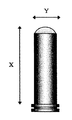
- X in FIG. 4 is 136 mm
- Y is 25 mm.
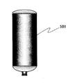
- This preform was put into a blow molding apparatus shown in FIG. 2 and molded under the following conditions to obtain a bottle-shaped molded product 501 shown in FIG.
- the obtained bottle-shaped molded product 501 was inserted into a seamless cylindrical mold.
- a mold formed by an electroforming method was used as the seamless cylindrical mold at this time.
- the bottom mold and the shoulder mold were attached, 0.05 MPa of air was introduced into the bottle, and the bottle mouth portion was sealed.
- the seamless cylindrical mold was placed in a heating device and heated from 25 ° C. to 190 ° C. over 100 seconds with a halogen heater while rotating at 30 rpm. After reaching 190 ° C., air was applied to cool the mold temperature to 25 ° C. over 50 seconds. Then, when the bottle-shaped molding heat-processed from the seamless cylindrical metal mold
- the upper and lower ends of the heat-treated bottle-shaped molded product were cut with an ultrasonic cutter to obtain an electrophotographic belt having a length of 250 mm and a diameter of 119 mm.
- the average film thickness of this electrophotographic belt was 71 ⁇ m, and the film thickness unevenness at the center of the belt was 71 ⁇ 5 ⁇ m.
- the produced electrophotographic belt was evaluated as follows. (Surface roughness) Arithmetic average roughness (Ra) and ten-point average roughness (Rzjis) were measured using a surface roughness measuring device (trade name: KOSAKA-SE3500, manufactured by Nihonkai Keikokuki Co., Ltd.). For the measurement, a 30 mm ⁇ 30 mm test piece was cut out from the central portion of the produced electrophotographic seamless belt and used as a sample. The sample was fixed to the sample stage with an adhesive, the measurement terminal was brought into contact with the sample, and measurement was performed by scanning a distance of 4.0 mm at a speed of 0.1 mm / sec in the belt width direction.
- the electrophotographic belt was used as an intermediate transfer belt in a full-color electrophotographic apparatus (FIG. 1), and a solid black image was printed on paper.
- the paper was placed in an environment of a temperature of 23 ° C. and a humidity of 45% RH for 1 day and used for the above image evaluation. The evaluation was performed by visually evaluating the secondary transferability of the image printed on the 10th sheet.
- FIG. 1 is a photosensitive drum
- 2 is a shaft
- 3 is a primary charger
- 4 is image exposure light from an image exposure means (not shown)
- 5C, 5K, 5M and 5Y are cyan, black, magenta and yellow.
- 6p and 6s are transfer members
- 7 is a cleaning member
- 7r is an auxiliary roller
- 8 is a fixing device
- 11 is an intermediate transfer member
- 12 is a tension roller
- 13 is a cleaning device
- P is paper or the like.
- the transfer medium is shown.
- Example 2 Preparation of electrophotographic belt> An electrophotographic belt was obtained in the same manner as in Example 1 except that the materials shown in Table 1-2 were used.
- the average film thickness of the electrophotographic belt was 68 ⁇ m, and the film thickness unevenness at the center of the belt was 68 ⁇ 5 ⁇ m.
- Example 3 Preparation of electrophotographic belt> An electrophotographic belt was obtained in the same manner as in Example 1 except that the materials listed in Table 1-3 were used. The average film thickness of this belt was 69 ⁇ m, and the film thickness unevenness at the center of the belt was 69 ⁇ 6 ⁇ m.
- Example 4 Preparation of electrophotographic belt> An electrophotographic belt was obtained in the same manner as in Example 1 except that the materials listed in Table 1-4 below were used. The average film thickness of this belt was 72 ⁇ m, and the film thickness unevenness at the center of the belt was 72 ⁇ 6 ⁇ m.
- Example 5 Preparation of electrophotographic belt> An electrophotographic belt was obtained in the same manner as in Example 1 except that the materials shown in Table 1-5 below were used. The average film thickness of this belt was 71 ⁇ m, and the film thickness unevenness at the center of the belt was 69 ⁇ 6 ⁇ m.
- Example 6 Preparation of electrophotographic belt> An electrophotographic belt was obtained in the same manner as in Example 1 except that the materials shown in Table 1-6 were used. The average film thickness of this belt was 69 ⁇ m, and the film thickness unevenness at the center of the belt was 70 ⁇ 6 ⁇ m.
Landscapes
- Chemical & Material Sciences (AREA)
- Health & Medical Sciences (AREA)
- Chemical Kinetics & Catalysis (AREA)
- Medicinal Chemistry (AREA)
- Polymers & Plastics (AREA)
- Organic Chemistry (AREA)
- Physics & Mathematics (AREA)
- General Physics & Mathematics (AREA)
- Electrostatic Charge, Transfer And Separation In Electrography (AREA)
- Electrophotography Configuration And Component (AREA)
- Compositions Of Macromolecular Compounds (AREA)
Abstract
Description

(上記式(I)において、R1~R4は各々独立に炭素数1~20の1価の炭化水素基を表す。Xは炭素数2~20の2価の炭化水素基を表す。aは2~10の整数を表す。また、bは1~4000の整数を表す。)。
(A)ポリアルキレンテレフタレートおよびポリアルキレンナフタレートから選ばれる少なくとも一方;
(B)熱可塑性シリコーンエラストマー。
そして、上記(B)の熱可塑性シリコーンエラストマーは、下記構造式(I)で表される繰り返し単位を有する。
構造式(I)
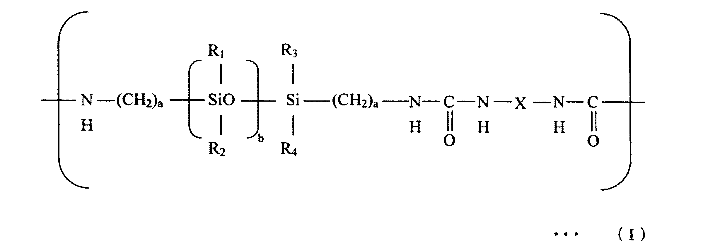
上記構造式(I)において、R1~R4は、各々独立に炭素数1~20の1価の炭化水素基を表す。Xは、炭素数2~20の2価の炭化水素基を表す。また、aは2~10、bは1~4000の整数を表す。
ポリアルキレンテレフタレートおよびポリアルキレンナフタレートから選ばれる少なくとも一方は、後述する成分(B)の熱可塑性シリコーンエラストマーに対するマトリックス樹脂として機能する。ポリアルキレンナフタレートとしては、ポリエチレンナフタレートを特に好適に用いることができる。また、ポリアルキレンテレフタレートとしては、ポリエチレンテレフタレートを好適に用いることができる。そして、本発明においてはポリアルキレンテレフタレートを1種または2種以上を任意の割合で混合してもよい。
成分(B)に係る熱可塑性シリコーンエラストマーは、前記式(I)で表される繰り返し単位を有する。式(I)から明らかなように、本発明にかかる熱可塑性シリコーンエラストマーは、分子骨格中にシロキサン結合を有するポリジメチルシロキサンセグメントと、ウレア結合(-NH-CO-NH-)を有する結晶性セグメントとを有している。

本発明に係るシームレス形状の電子写真用ベルトの成形方法には、例えば遠心成形、チューブ押出、インフレーション成形、押出成形、円筒押出成形、ブロー成形などが挙げられる。これらの中で、図2に示すブロー成形が特に好ましい。図2において、101は試験管形状のプリフォーム、102は加熱炉、103はブロー型、104は延伸棒、105はブロー成形品、および106はエア流入口を示す。
140℃で6時間以上乾燥させた前記マトリックス樹脂と熱可塑性シリコーンエラストマーをニ軸押出し機により、260℃で熔融混練する。均一に混合された各成分を、直径2mm程度のストランドとして押し出して冷水で固化し、カットしてペレットを作製する。樹脂中に水分を含んでいると成形性が低下するため、作製したペレットを140℃で6時間以上乾燥させる。乾燥させたペレットを、図3に示すような射出成形装置に投入し、285℃に調節して射出成形を行い、図4に示すようなプリフォームを作製する。図3において、107はホッパー、108は射出成形装置、109はキャビティ型、および110はコア型、および111はキャビティに充填された樹脂により成形されたプリフォームを示す。
<電子写真用ベルトの作製>
下記表1-1の材料を2軸の押し出し機により温度260℃で熔融混練して各成分を均一に混合し、直径2mm程度のストランドとして押し出し、次いで該ストランドをカットしてペレット化した。これを成形用原料(1)とした。

*:「GENIOMER140」は前記式(I)においてXが炭素数=13の4,4’-ジシクロヘキシルメチル基であり、a=3、b=39であり、かつ、重量平均分子量(Mn)が約36000である。
・ 縦方向延伸倍率 3.2倍;
・ 横方向延伸倍率 4.9倍;
・ 加熱位置 プリフォームを縦方向に5分割;
・ プリフォーム中心位置の温度 160℃;
・ 一次圧力 0.8MPa;
・ 延伸棒が移動を始めてから気体を流入するまでの時間 0.3sec;
・ 二次圧力 0.8MPa;
・ ブロー金型温度 15℃。
作製した電子写真用ベルトを以下のように評価した。
(表面粗さ)
算術平均粗さ(Ra)および十点平均粗さ(Rzjis)を表面粗さ測定機(商品名:KOSAKA-SE3500、日本海計測特機株式会社製)を用いて測定した。測定は作製した電子写真用シームレスベルトの中央部から30mm×30mmの試験片を切り出し、これをサンプルとして使用した。サンプルを試料台に接着剤で固定し、測定端子をサンプルに接触させ、ベルト幅方向に0.1mm/secの速度で距離4.0mmを走査して測定を行った。
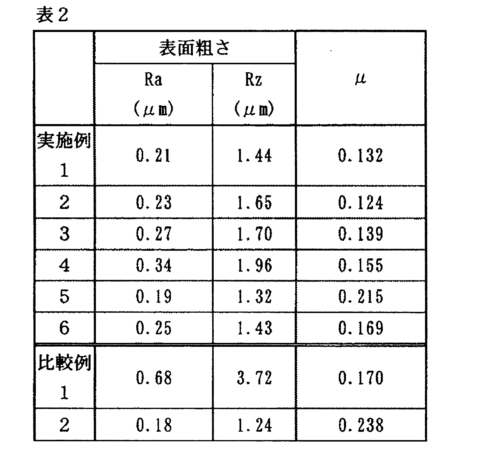
測定にはフリクションプレイヤー(商品名:FPR-2100型、RHESCA社製)を用いた。測定サンプルとしては、電子写真用シームレスベルトの中央部から切り出した30mm×30mmの試験片を用いた。測定端子と測定サンプルとの間に荷重を与えるため、ボール付き測定端子上に300gの重りを固定し、測定サンプルの表面と接触させた後、回転半径10mm、回転速度10rpm、回転数100回転の条件でベルト表面上を時計回りに円運動させて測定を行った。上記表面粗さ、および摩擦係数の測定結果を表2に示す。
電子写真用ベルトを中間転写ベルトとしてフルカラーの電子写真装置(図1)に装着し、紙にベタ黒の画像を印字した。紙には、算術平均粗さ(Ra)=4.0μm、十点平均粗さ(Rzjis)=15μmの表面が粗い紙を用いた。また、紙は、温度23℃、湿度45%RHの環境下に1日置いて上記の画像評価に用いた。評価は、10枚目にプリントされた画像について、目視で二次転写性を評価した。
さらに続けてフルカラー画像を1万枚プリントした後の画像を耐久画像(1)とし、目視で二次転写性の評価をしたところ、画像域の部分的に小さな転写ムラが確認されたが画質は良好であった。
<電子写真用ベルトの作製>
下記表1-2の材料を用いた以外は、実施例1と同様にして電子写真用ベルトを得た。この電子写真用ベルトの平均膜厚は68μm、ベルト中心部の膜厚ムラは68±5μmであった。
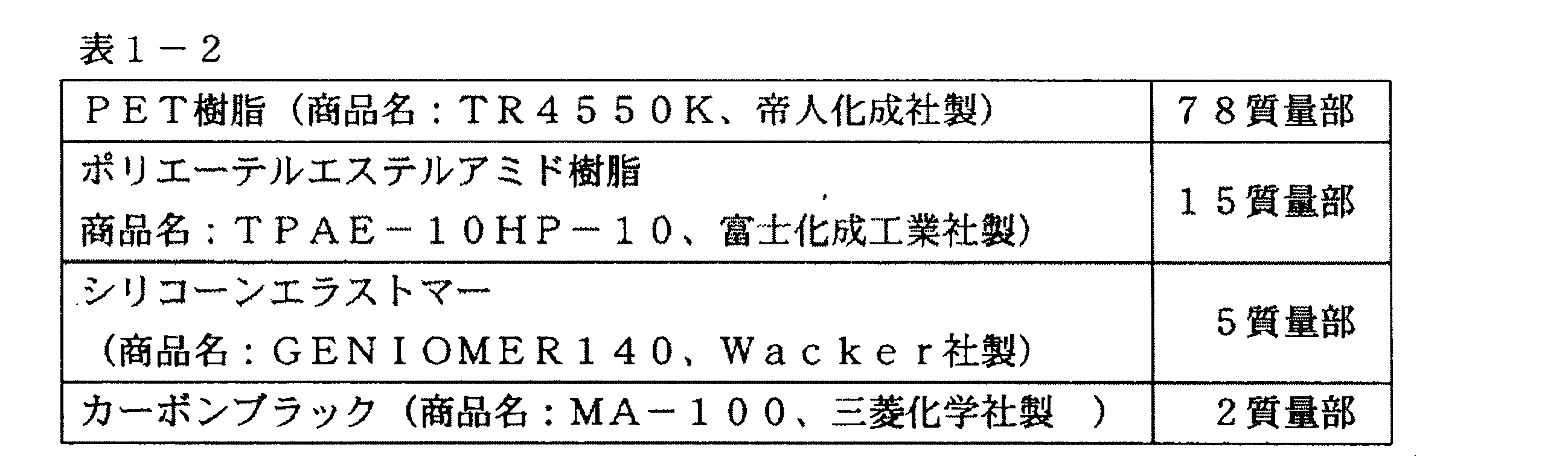
作製した電子写真用ベルトの表面粗さ、摩擦係数を実施例1と同様に測定した。その結果を下記表2に示す。また、実施例1と同様にして画像評価を行なった。その結果、(画像評価1)については、転写ムラは確認できず画質は非常に良好であった。
<電子写真用ベルトの作製>
下記表1-3に記載の材料を用いた以外は、実施例1と同様にして電子写真用ベルトを得た。このベルトの平均膜厚は69μm、ベルト中心部の膜厚ムラは69±6μmであった。
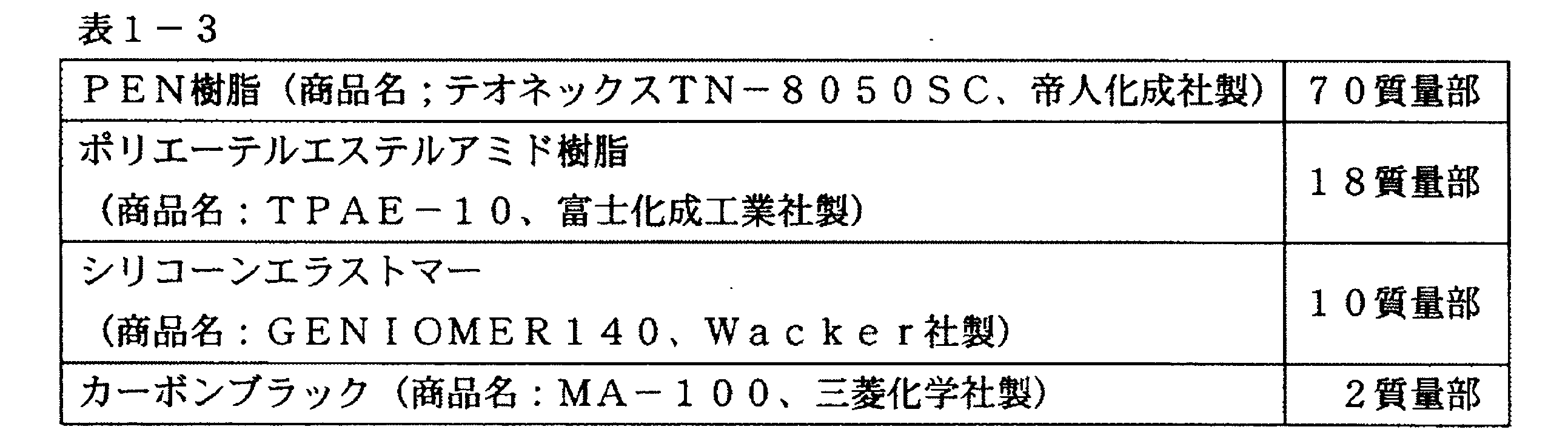
作製した電子写真用ベルトの表面粗さ、摩擦係数を実施例1と同様に測定した。その結果を下記表2に示す。また、実施例1と同様にして画像評価を行なった。その結果、(画像評価1)については転写ムラは確認できず画質は非常に良好であった。
また、(画像評価2)については、画像域の全体に渡って小さな転写ムラが確認されたが画質は良好であった。
<電子写真用ベルトの作製>
下記表1-4に記載の材料を用いた以外は、実施例1と同様にして電子写真用ベルトを得た。このベルトの平均膜厚は72μm、ベルト中心部の膜厚ムラは72±6μmであった。
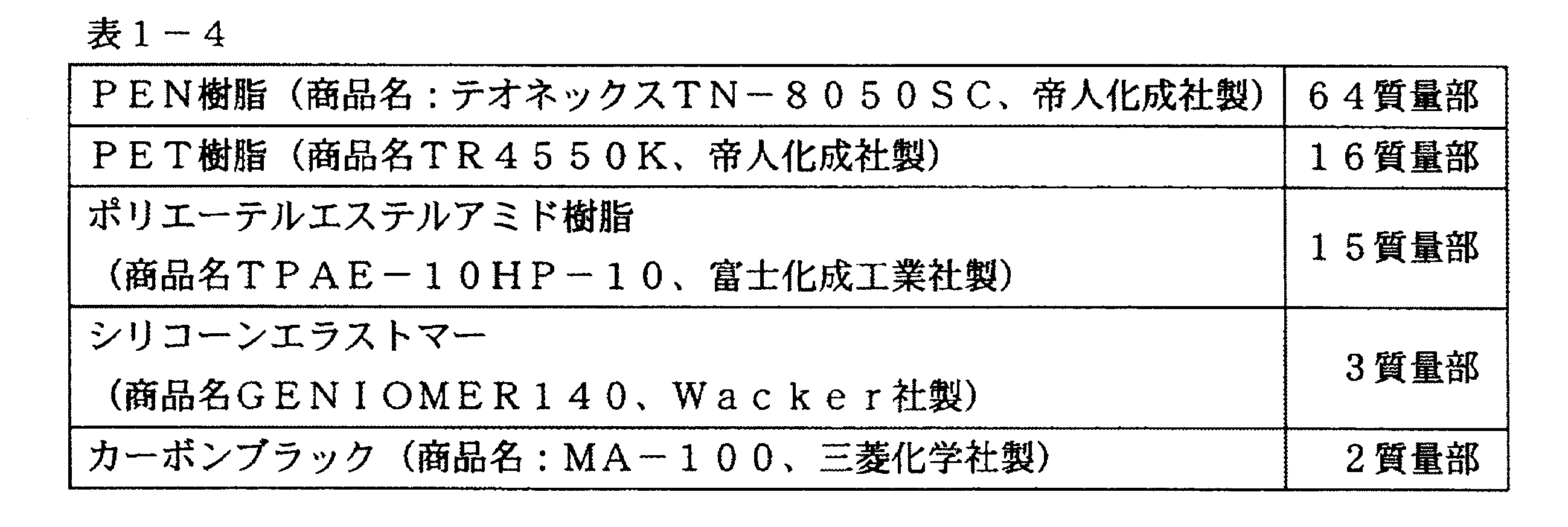
作製した電子写真用ベルト(4)の表面粗さ、摩擦係数を実施例1と同様に測定した。その結果を下記表2に示す。また、実施例1と同様にして画像評価を行なった。その結果、(画像評価1)については、画像域の部分的に小さな転写ムラが確認されたが画質は良好であった。また、(画像評価2)については、画像域の全体に渡って小さな転写ムラが確認されたが画質は良好であった。
<電子写真用ベルトの作製>
下記表1-5の材料を用いた以外は、実施例1と同様にして電子写真用ベルトを得た。このベルトの平均膜厚は71μm、ベルト中心部の膜厚ムラは69±6μmであった。
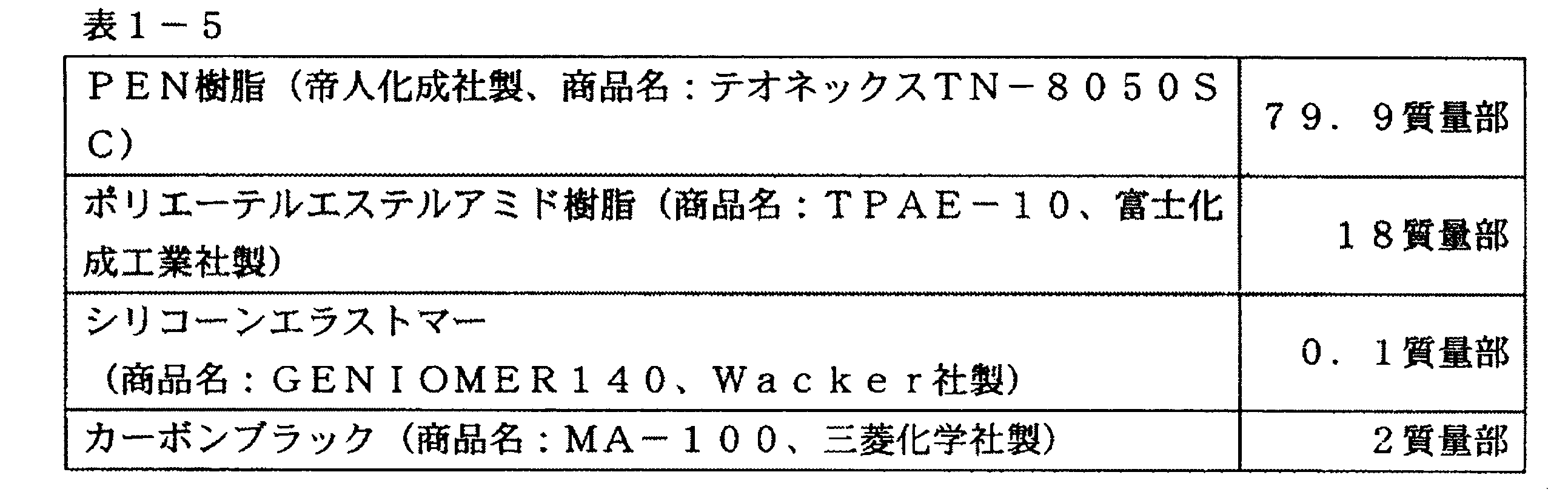
作製した電子写真用ベルトの表面粗さ、摩擦係数を実施例1と同様に測定した。その結果を下記表2に示す。また、実施例1と同様にして画像評価を行なった。その結果、(画像評価1)については、画像域の部分的に小さな転写ムラが確認されたが画質は良好であった。また、(画像評価2)については、画像域の全体に渡って小さな転写ムラが確認されたが画質は良好であった。
<電子写真用ベルトの作製>
下記表1-6の材料を用いた以外は、実施例1と同様にして電子写真用ベルトを得た。このベルトの平均膜厚は69μm、ベルト中心部の膜厚ムラは70±6μmであった。

*「GENIOMER 140改」は、上記式(I)においてXがエチレン基である。
作製した電子写真用ベルトの表面粗さ、摩擦係数を実施例1と同様に測定した。その結果を下記表2に示す。また、実施例1と同様にして画像評価を行なった。その結果、(画像評価1)については、画像域に部分的に小さな転写ムラが確認されたが画質は良好であった。また、(画像評価2)については、画像域の全体に渡って小さな転写ムラが確認されたが画質は良好であった。
<電子写真用ベルトの作製>
下記表1-7の材料を用いた以外は、実施例1と同様にして電子写真用ベルトを得た。このベルトの平均膜厚は73μm、ベルト中心部の膜厚ムラは73±10μmであった。

作製した電子写真用ベルトの表面粗さ、摩擦係数を実施例1と同様に測定した。その結果を下記表2に示す。また、実施例1と同様にして画像評価を行なった。その結果、(画像評価1)については、画像域に部分的に大きな転写ムラが確認された。また、(画像評価2)については、画像域全体にわたって大きな転写ムラが確認された。
<電子写真用ベルトの作製>
下記表1-8に記載の材料を用いた以外は、実施例1と同様にして電子写真用ベルトを得た。このベルトの平均膜厚は70μm、ベルト中心部の膜厚ムラは70±4μmであった。
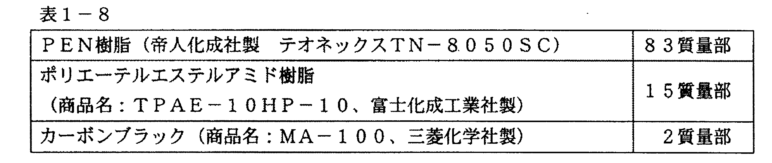
作製した電子写真用ベルトの表面粗さ、摩擦係数を実施例1と同様に測定した。その結果を下記表2に示す。また、実施例1と同様にして画像評価を行なった。その結果、(画像評価1)については、画像域全体にわたって小さな転写ムラが確認された。また、(画像評価2)については、画像域全体にわたって大きな転写ムラが確認された。
Claims (5)
- (A)ポリアルキレンテレフタレートおよびポリアルキレンナフタレートから選ばれる少なくとも一方と、
(B)下記式(I)で表される繰り返し単位を有する熱可塑性シリコーンエラストマーとを含有することを特徴とする電子写真用ベルト:

(式(1)において、R1~R4は各々独立に炭素数1~20の1価の炭化水素基を表し、Xは炭素数2~20の2価の炭化水素基を表し、aは2~10の整数を表し、bは1~4000の整数を表す)。 - 前記式(I)において、R1~R4がメチル基であり、Xが4,4’-ジシクロヘキシルメチル基である請求項1に記載の電子写真用ベルト。
- 前記ポリアルキレンテレフタレートがポリエチレンテレフタレートである請求項1または2に記載の電子写真用ベルト。
- 前記ポリアルキレンナフタレートが、ポリエチレンナフタレートである請求項1~3のいずれか1項に記載の電子写真用ベルト。
- 請求項1~4のいずれか1項に記載の電子写真用ベルトを中間転写ベルトとして具備していることを特徴とする電子写真装置。
Priority Applications (3)
| Application Number | Priority Date | Filing Date | Title |
|---|---|---|---|
| KR1020127019109A KR101417552B1 (ko) | 2009-12-28 | 2010-12-21 | 전자 사진용 벨트 및 전자 사진 장치 |
| CN201080055510.9A CN102640062B (zh) | 2009-12-28 | 2010-12-21 | 电子照相带和电子照相设备 |
| US13/104,322 US8216690B2 (en) | 2009-12-28 | 2011-05-10 | Electrophotographic belt and electrophotographic apparatus |
Applications Claiming Priority (2)
| Application Number | Priority Date | Filing Date | Title |
|---|---|---|---|
| JP2009297563 | 2009-12-28 | ||
| JP2009-297563 | 2009-12-28 |
Related Child Applications (1)
| Application Number | Title | Priority Date | Filing Date |
|---|---|---|---|
| US13/104,322 Continuation US8216690B2 (en) | 2009-12-28 | 2011-05-10 | Electrophotographic belt and electrophotographic apparatus |
Publications (1)
| Publication Number | Publication Date |
|---|---|
| WO2011080893A1 true WO2011080893A1 (ja) | 2011-07-07 |
Family
ID=44226321
Family Applications (1)
| Application Number | Title | Priority Date | Filing Date |
|---|---|---|---|
| PCT/JP2010/007403 Ceased WO2011080893A1 (ja) | 2009-12-28 | 2010-12-21 | 電子写真用ベルト及び電子写真装置 |
Country Status (5)
| Country | Link |
|---|---|
| US (1) | US8216690B2 (ja) |
| JP (1) | JP5679800B2 (ja) |
| KR (1) | KR101417552B1 (ja) |
| CN (1) | CN102640062B (ja) |
| WO (1) | WO2011080893A1 (ja) |
Families Citing this family (3)
| Publication number | Priority date | Publication date | Assignee | Title |
|---|---|---|---|---|
| JP2015155531A (ja) * | 2014-01-17 | 2015-08-27 | キヤノン株式会社 | 結晶性熱可塑性樹脂組成物の製造方法、電子写真用部材の製造方法、及び電子写真用ベルトの製造方法 |
| US20150370199A1 (en) * | 2014-06-23 | 2015-12-24 | Canon Kabushiki Kaisha | Electrophotographic belt and electrophotographic image forming apparatus |
| KR102523269B1 (ko) | 2022-06-28 | 2023-04-24 | 한국지질자원연구원 | 바나듐 광석의 다단 배소-침출을 통한 바나듐 침출 방법 |
Citations (3)
| Publication number | Priority date | Publication date | Assignee | Title |
|---|---|---|---|---|
| JPH04216562A (ja) * | 1990-02-26 | 1992-08-06 | Minnesota Mining & Mfg Co <3M> | 静電的多色トナー画像形成方法およびレセプターシート |
| JPH10100168A (ja) * | 1996-10-02 | 1998-04-21 | Tokai Denka Kogyo Kk | 半導電性ポリエステル樹脂製シームレスベルト |
| JP2005316040A (ja) * | 2004-04-28 | 2005-11-10 | Konica Minolta Business Technologies Inc | 転写ベルトおよび該ベルトを有する画像形成装置 |
Family Cites Families (2)
| Publication number | Priority date | Publication date | Assignee | Title |
|---|---|---|---|---|
| US5250994A (en) | 1991-10-30 | 1993-10-05 | Canon Kabushiki Kaisha | Image forming apparatus having transfer member supporting member |
| JPH07149061A (ja) * | 1994-09-19 | 1995-06-13 | Dainippon Printing Co Ltd | 熱転写受像シート |
-
2010
- 2010-12-21 CN CN201080055510.9A patent/CN102640062B/zh not_active Expired - Fee Related
- 2010-12-21 JP JP2010284757A patent/JP5679800B2/ja not_active Expired - Fee Related
- 2010-12-21 KR KR1020127019109A patent/KR101417552B1/ko not_active Expired - Fee Related
- 2010-12-21 WO PCT/JP2010/007403 patent/WO2011080893A1/ja not_active Ceased
-
2011
- 2011-05-10 US US13/104,322 patent/US8216690B2/en not_active Expired - Fee Related
Patent Citations (3)
| Publication number | Priority date | Publication date | Assignee | Title |
|---|---|---|---|---|
| JPH04216562A (ja) * | 1990-02-26 | 1992-08-06 | Minnesota Mining & Mfg Co <3M> | 静電的多色トナー画像形成方法およびレセプターシート |
| JPH10100168A (ja) * | 1996-10-02 | 1998-04-21 | Tokai Denka Kogyo Kk | 半導電性ポリエステル樹脂製シームレスベルト |
| JP2005316040A (ja) * | 2004-04-28 | 2005-11-10 | Konica Minolta Business Technologies Inc | 転写ベルトおよび該ベルトを有する画像形成装置 |
Also Published As
| Publication number | Publication date |
|---|---|
| JP2011154355A (ja) | 2011-08-11 |
| KR101417552B1 (ko) | 2014-07-08 |
| CN102640062B (zh) | 2015-01-07 |
| CN102640062A (zh) | 2012-08-15 |
| JP5679800B2 (ja) | 2015-03-04 |
| US8216690B2 (en) | 2012-07-10 |
| KR20120099496A (ko) | 2012-09-10 |
| US20110213097A1 (en) | 2011-09-01 |
Similar Documents
| Publication | Publication Date | Title |
|---|---|---|
| CN104903797B (zh) | 电子照相用带和其制造方法,和电子照相图像形成设备 | |
| WO2005010621A1 (ja) | 画像形成装置用エンドレスベルト及び画像形成装置 | |
| US5424352A (en) | Heat-conductive silicone rubber composition | |
| JP5679800B2 (ja) | 電子写真用ベルト及び電子写真装置 | |
| JP5162911B2 (ja) | 画像形成装置用エンドレスベルト及び画像形成装置 | |
| CN1837987B (zh) | 定影辊或定影带用绝缘性硅橡胶组合物以及定影辊和定影带 | |
| JP5347356B2 (ja) | 画像形成装置用エンドレスベルト及び画像形成装置 | |
| JP2006267626A (ja) | 画像形成装置用エンドレスベルト及び画像形成装置 | |
| JP2002202668A (ja) | エンドレスベルト、画像形成装置用ベルト及び画像形成装置 | |
| JP3925508B2 (ja) | 転写ベルトおよび該ベルトを有する画像形成装置 | |
| JP4438829B2 (ja) | 成形体および画像形成装置 | |
| WO2021246263A1 (ja) | スポンジローラ | |
| JP2025018104A (ja) | シリコーンゴム組成物、及びシリコーン熱収縮チューブ | |
| WO2025004963A1 (ja) | スポンジローラ | |
| CN100444042C (zh) | 图像形成装置用环形带及图像形成装置 | |
| JP3983424B2 (ja) | シームレスベルト、画像形成装置用ベルト及び画像形成装置 | |
| JP2009020154A (ja) | 電子写真用転写ベルト | |
| JP5082464B2 (ja) | 画像形成装置用エンドレスベルト及び画像形成装置 | |
| JP2000248086A (ja) | 耐久・耐熱性シームレス管状フィルム及びその使用 | |
| JP3582486B2 (ja) | 成形部材、エンドレスベルト、画像形成装置用ベルト及び画像形成装置 | |
| JP2001305891A (ja) | シームレスベルト、画像形成装置用ベルト及び画像形成装置 | |
| JP2007047810A (ja) | シームレスベルト、画像形成装置用ベルト及び画像形成装置 | |
| JP2001302812A (ja) | エンドレスベルト、画像形成装置用ベルト及び画像形成装置 | |
| JP2005164673A (ja) | 電子写真装置用エンドレスベルト、ベルトカートリッジ、プロセスカートリッジ及び画像形成装置 | |
| JP2001282011A (ja) | エンドレスベルト、画像形成装置用ベルト及び画像形成装置 |
Legal Events
| Date | Code | Title | Description |
|---|---|---|---|
| WWE | Wipo information: entry into national phase |
Ref document number: 201080055510.9 Country of ref document: CN |
|
| 121 | Ep: the epo has been informed by wipo that ep was designated in this application |
Ref document number: 10840753 Country of ref document: EP Kind code of ref document: A1 |
|
| NENP | Non-entry into the national phase |
Ref country code: DE |
|
| ENP | Entry into the national phase |
Ref document number: 20127019109 Country of ref document: KR Kind code of ref document: A |
|
| 122 | Ep: pct application non-entry in european phase |
Ref document number: 10840753 Country of ref document: EP Kind code of ref document: A1 |