WO2011077904A1 - コネクティングロッドおよびそれを備えた単気筒内燃機関ならびに鞍乗型車両 - Google Patents
コネクティングロッドおよびそれを備えた単気筒内燃機関ならびに鞍乗型車両 Download PDFInfo
- Publication number
- WO2011077904A1 WO2011077904A1 PCT/JP2010/071328 JP2010071328W WO2011077904A1 WO 2011077904 A1 WO2011077904 A1 WO 2011077904A1 JP 2010071328 W JP2010071328 W JP 2010071328W WO 2011077904 A1 WO2011077904 A1 WO 2011077904A1
- Authority
- WO
- WIPO (PCT)
- Prior art keywords
- connecting rod
- less
- large end
- inner peripheral
- peripheral surface
- Prior art date
- Legal status (The legal status is an assumption and is not a legal conclusion. Google has not performed a legal analysis and makes no representation as to the accuracy of the status listed.)
- Ceased
Links
Images





Classifications
-
- F—MECHANICAL ENGINEERING; LIGHTING; HEATING; WEAPONS; BLASTING
- F16—ENGINEERING ELEMENTS AND UNITS; GENERAL MEASURES FOR PRODUCING AND MAINTAINING EFFECTIVE FUNCTIONING OF MACHINES OR INSTALLATIONS; THERMAL INSULATION IN GENERAL
- F16C—SHAFTS; FLEXIBLE SHAFTS; ELEMENTS OR CRANKSHAFT MECHANISMS; ROTARY BODIES OTHER THAN GEARING ELEMENTS; BEARINGS
- F16C7/00—Connecting-rods or like links pivoted at both ends; Construction of connecting-rod heads
- F16C7/02—Constructions of connecting-rods with constant length
- F16C7/023—Constructions of connecting-rods with constant length for piston engines, pumps or the like
-
- C—CHEMISTRY; METALLURGY
- C21—METALLURGY OF IRON
- C21D—MODIFYING THE PHYSICAL STRUCTURE OF FERROUS METALS; GENERAL DEVICES FOR HEAT TREATMENT OF FERROUS OR NON-FERROUS METALS OR ALLOYS; MAKING METAL MALLEABLE, e.g. BY DECARBURISATION OR TEMPERING
- C21D1/00—General methods or devices for heat treatment, e.g. annealing, hardening, quenching or tempering
- C21D1/06—Surface hardening
-
- C—CHEMISTRY; METALLURGY
- C21—METALLURGY OF IRON
- C21D—MODIFYING THE PHYSICAL STRUCTURE OF FERROUS METALS; GENERAL DEVICES FOR HEAT TREATMENT OF FERROUS OR NON-FERROUS METALS OR ALLOYS; MAKING METAL MALLEABLE, e.g. BY DECARBURISATION OR TEMPERING
- C21D1/00—General methods or devices for heat treatment, e.g. annealing, hardening, quenching or tempering
- C21D1/68—Temporary coatings or embedding materials applied before or during heat treatment
- C21D1/70—Temporary coatings or embedding materials applied before or during heat treatment while heating or quenching
-
- C—CHEMISTRY; METALLURGY
- C21—METALLURGY OF IRON
- C21D—MODIFYING THE PHYSICAL STRUCTURE OF FERROUS METALS; GENERAL DEVICES FOR HEAT TREATMENT OF FERROUS OR NON-FERROUS METALS OR ALLOYS; MAKING METAL MALLEABLE, e.g. BY DECARBURISATION OR TEMPERING
- C21D9/00—Heat treatment, e.g. annealing, hardening, quenching or tempering, adapted for particular articles; Furnaces therefor
-
- C—CHEMISTRY; METALLURGY
- C22—METALLURGY; FERROUS OR NON-FERROUS ALLOYS; TREATMENT OF ALLOYS OR NON-FERROUS METALS
- C22C—ALLOYS
- C22C38/00—Ferrous alloys, e.g. steel alloys
- C22C38/02—Ferrous alloys, e.g. steel alloys containing silicon
-
- C—CHEMISTRY; METALLURGY
- C22—METALLURGY; FERROUS OR NON-FERROUS ALLOYS; TREATMENT OF ALLOYS OR NON-FERROUS METALS
- C22C—ALLOYS
- C22C38/00—Ferrous alloys, e.g. steel alloys
- C22C38/18—Ferrous alloys, e.g. steel alloys containing chromium
-
- C—CHEMISTRY; METALLURGY
- C23—COATING METALLIC MATERIAL; COATING MATERIAL WITH METALLIC MATERIAL; CHEMICAL SURFACE TREATMENT; DIFFUSION TREATMENT OF METALLIC MATERIAL; COATING BY VACUUM EVAPORATION, BY SPUTTERING, BY ION IMPLANTATION OR BY CHEMICAL VAPOUR DEPOSITION, IN GENERAL; INHIBITING CORROSION OF METALLIC MATERIAL OR INCRUSTATION IN GENERAL
- C23C—COATING METALLIC MATERIAL; COATING MATERIAL WITH METALLIC MATERIAL; SURFACE TREATMENT OF METALLIC MATERIAL BY DIFFUSION INTO THE SURFACE, BY CHEMICAL CONVERSION OR SUBSTITUTION; COATING BY VACUUM EVAPORATION, BY SPUTTERING, BY ION IMPLANTATION OR BY CHEMICAL VAPOUR DEPOSITION, IN GENERAL
- C23C8/00—Solid state diffusion of only non-metal elements into metallic material surfaces; Chemical surface treatment of metallic material by reaction of the surface with a reactive gas, leaving reaction products of surface material in the coating, e.g. conversion coatings, passivation of metals
- C23C8/06—Solid state diffusion of only non-metal elements into metallic material surfaces; Chemical surface treatment of metallic material by reaction of the surface with a reactive gas, leaving reaction products of surface material in the coating, e.g. conversion coatings, passivation of metals using gases
- C23C8/34—Solid state diffusion of only non-metal elements into metallic material surfaces; Chemical surface treatment of metallic material by reaction of the surface with a reactive gas, leaving reaction products of surface material in the coating, e.g. conversion coatings, passivation of metals using gases more than one element being applied in more than one step
Definitions
- the present invention relates to a connecting rod, and more particularly to a connecting rod formed from an iron alloy.
- the present invention also relates to a single-cylinder internal combustion engine and a straddle-type vehicle provided with such a connecting rod.
- a member called a connecting rod (sometimes abbreviated as “con'rod”) is used to connect a piston and a crankshaft.
- the connecting rod includes a rod-shaped rod main body, a small end provided at one end of the rod main body, and a large end provided at the other end of the rod main body. The small end is connected to the piston, while the large end is connected to the crankshaft. More specifically, the piston pin of the piston is inserted through the through hole formed in the small end portion. A crank pin of the crankshaft is inserted through a through hole formed at the large end. Thereby, the connecting rod is connected to the piston and the crankshaft.
- ⁇ Connecting rods are roughly divided into a split type with the large end divided into two and an integrated type with the large end not split.
- the integral connecting rod is mainly used for a single cylinder internal combustion engine.
- ⁇ Rolling bearings such as needle bearings and ball bearings are arranged between the inner peripheral surface of the large end of the integral connecting rod and the crank pin in order to reduce friction loss.
- the explosive force transmitted through the piston during operation of the internal combustion engine presses the connecting rod against the rolling bearing, so that a large stress is generated on the inner peripheral surface of the large end. When this stress is excessive, a fatigue fracture phenomenon called flaking occurs on the inner peripheral surface of the large end.
- Patent Document 1 proposes high-concentration carburizing treatment as a technique for further increasing the surface hardness of the connecting rod.
- carburization is performed a plurality of times in an atmosphere having a carbon potential (CP) of 0.8% or more.
- CP carbon potential
- Patent Document 1 also mentions high-concentration carbonitriding as a technique for increasing the surface hardness of the connecting rod, as in high-concentration carburizing.
- the present invention has been made in view of the above problems, and an object of the present invention is to provide a connecting rod that suppresses the occurrence of flaking on the inner peripheral surface of the large end and has excellent fatigue strength.
- a connecting rod according to the present invention includes a rod body, a small end provided at one end of the rod body, and a large end provided at the other end of the rod body, and is formed of an iron alloy.
- the connecting rod according to the present invention has a nitrogen content of 0.04 wt% or more and 0.18 wt% or less at a depth of 0.1 mm from the inner peripheral surface of the large end.
- the connecting rod according to the present invention has a nitrogen content of 0.05 wt% or more and 0.15 wt% or less at a depth of 0.1 mm from the inner peripheral surface of the large end.
- the iron alloy includes 0.1 wt% or more and 0.4 wt% or less of carbon, 0.1 wt% or more and 0.5 wt% or less of silicon, and 0.3 wt% or more and 1.2 wt% or less of chromium. including.
- the iron alloy has a nickel content of less than 0.7 wt%.
- the connecting rod according to the present invention has a non-diffusible hydrogen content of 0.46 ppm or less.
- the carbonitriding process, the carburizing process, and the nitriding process are performed in a furnace that is depressurized to 1/10 or less of standard atmospheric pressure.
- the particle size of the carbide and carbonitride precipitated in the vicinity of the inner peripheral surface of the large end is 10 ⁇ m or less.
- a single-cylinder internal combustion engine includes a connecting rod having the above configuration, and a crankshaft connected to the connecting rod.
- the crankshaft includes a crankpin inserted into the large end portion of the connecting rod, and a crank web formed separately from the crankpin.
- the single-cylinder internal combustion engine according to the present invention further includes a rolling bearing provided between the inner peripheral surface of the large end portion and the crank pin.
- crank pin is subjected to a carburizing process or a carbonitriding process.
- a straddle-type vehicle according to the present invention includes a single-cylinder internal combustion engine having the above-described configuration.
- a method for manufacturing a connecting rod according to the present invention includes a rod main body, a small end provided at one end of the rod main body, and a large end provided at the other end of the rod main body.
- the carburizing treatment in the step (B) and the carbonitriding treatment in the step (C) are performed in a furnace reduced in pressure to 1/10 or less of standard atmospheric pressure.
- a method of manufacturing a connecting rod according to the present invention includes a rod main body, a small end provided at one end of the rod main body, and a large end provided at the other end of the rod main body.
- the process is performed so that the nitrogen content at a depth of 0.1 mm from the inner peripheral surface of the region is 0.03 wt% or more and 0.19 wt% or less.
- the carburizing treatment in the step (B) and the nitriding treatment in the step (C) are performed in a furnace reduced in pressure to 1/10 or less of standard atmospheric pressure.
- the connecting rod according to the present invention is made of an iron alloy and is subjected to carbonitriding or carburizing and nitriding.
- carbonitriding or carburizing and nitriding
- the surface hardness of the connecting rod is increased and the fatigue strength is improved.
- the carbon content at a depth of 0.1 mm from the inner peripheral surface of the large end is 0.8 wt% or more and 2.1 wt% or less.
- CP carbon potential
- the connecting rod according to the present invention the nitrogen content at a predetermined depth from the inner peripheral surface of the large end portion is set within a specific range.
- the nitrogen content at a depth of 1 mm is 0.03 wt% or more and 0.19 wt% or less.
- the nitrogen content at a depth of 0.1 mm from the inner peripheral surface of the large end is preferably 0.04 wt% or more and 0.18 wt% or less, More preferably, it is 0.05 wt% or more and 0.15 wt% or less.
- the iron alloy which is the material of the connecting rod according to the present invention includes 0.1 wt% or more and 0.4 wt% or less of carbon, 0.1 wt% or more and 0.5 wt% or less of silicon, and 0.3 wt% or more and 1.2 wt% or less. Preferably it contains chromium.
- the carbon content is 0.1 wt% or more and 0.4 wt% or less
- the internal hardness of the connecting rod after the heat treatment can be 200 HV or more and 500 HV or less, so that the strength and toughness inside the connecting rod are sufficiently provided. Can be kept high. Further, when the silicon content is increased, the anti-flaking property is improved, but the toughness may be lowered.
- the silicon content is 0.1 wt% or more and 0.5 wt% or less, the flaking resistance can be sufficiently improved and sufficient toughness can be ensured.
- the chromium content is increased, the hardenability is improved.
- temper embrittlement may occur.
- the chromium content is 0.3 wt% or more and 1.2 wt% or less, the occurrence of temper embrittlement can be prevented while obtaining appropriate hardenability.
- the nickel content of the iron alloy is preferably as low as possible, specifically, less than 0.7 wt%. When the nickel content increases, the amount of retained austenite after heat treatment increases, so the surface hardness may decrease.
- the non-diffusible hydrogen content is preferably 0.46 ppm or less. Since the non-diffusible hydrogen content is 0.46 ppm or less, the occurrence of hydrogen brittle mold peeling can be suppressed, so that the flaking life can be further improved.
- the carbonitriding process (or carburizing process and nitriding process) is preferably performed in a vacuum-evacuated furnace, and more specifically, in a furnace reduced in pressure to 1/10 or less of the standard atmospheric pressure. Preferably it is applied.
- a gas containing nitrogen By introducing a gas containing nitrogen into such a furnace, the nitrogen content at a depth of 0.1 mm from the surface (the inner peripheral surface of the large end) can be adjusted with high accuracy.
- the particle size of the carbide and carbonitride precipitated in the vicinity of the inner peripheral surface of the large end is preferably as small as possible, specifically 10 ⁇ m or less.
- the particle size of the carbide and carbonitride exceeds 10 ⁇ m, the toughness may be lowered and sufficient strength may not be obtained.
- the connecting rod according to the present invention is preferably used for a single cylinder internal combustion engine having one cylinder.
- the crankshaft of a single cylinder internal combustion engine is typically an assembly type crankshaft. That is, the crankpin and the crank web are formed separately.
- a rolling bearing for example, a needle bearing or a ball bearing
- a rolling bearing is provided between the inner peripheral surface of the large end and the crank pin.
- stress is generated on the inner peripheral surface of the large end portion by pressing the connecting rod against the rolling bearing. If this stress is excessive, the occurrence of flaking is a concern.
- the connecting rod according to the present invention is excellent in anti-flaking property, the occurrence of flaking is prevented over a long period of time.
- crankpin is subjected to carburizing or carbonitriding.
- the single-cylinder internal combustion engine provided with the connecting rod according to the present invention is suitably used for various straddle-type vehicles (for example, motorcycles).
- a carbonitriding process or a carburizing process and a nitriding process are performed on a workpiece formed of an iron alloy.
- carbonitriding or carburizing and nitriding
- the surface hardness of the connecting rod is increased and the fatigue strength is improved.
- the carbonitriding process and the carburizing process are performed in an atmosphere having a carbon potential (CP) of 0.8% or more. That is, a high concentration carbonitriding process or a high concentration carburizing process is performed on the workpiece.
- the carbonitriding treatment or nitriding treatment has a nitrogen content of 0.03 wt% or more and 0.19 wt% or less at a predetermined depth from the inner peripheral surface of the region that becomes the large end of the workpiece. To be executed.
- the connecting rod manufactured by the manufacturing method according to the present invention has excellent fatigue strength as compared with a connecting rod that has been simply subjected to high-concentration carbonitriding or high-concentration carburizing.
- the carbonitriding process (or carburizing process and nitriding process) is preferably performed in a vacuum-evacuated furnace, and more specifically, in a furnace reduced in pressure to 1/10 or less of the standard atmospheric pressure. Preferably it is applied.
- a gas containing nitrogen By introducing a gas containing nitrogen into such a furnace, the nitrogen content at a depth of 0.1 mm from the surface (the inner peripheral surface of the large end) can be adjusted with high accuracy.
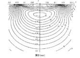
- FIG. 4 is a cross-sectional view taken along line 1C-1C ′ in FIG. It is a figure which shows the stress distribution (stress distribution when a stress becomes the maximum at the time of the driving
- FIG. 1 is a graph which shows distribution of the carbon concentration (carbon content) in the depth direction of the connecting rod. It is a graph which shows the hardness distribution in the depth direction of the connecting rod. It is a graph which shows the relationship between nitrogen content (wt%) in the depth of 0.1 mm from the internal peripheral surface of a large end part, and flaking lifetime (L50 lifetime). It is a flowchart which shows the manufacturing method of the connecting rod 1 in suitable embodiment of this invention.
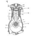
- FIG. 1 is a cross-sectional view schematically showing a single cylinder internal combustion engine 100 including a connecting rod 1 according to a preferred embodiment of the present invention.
- Fig. 11 is a side view schematically showing a motorcycle including the internal combustion engine 100 shown in Fig. 10.
- the inventor of the present application examined in detail the reason why flaking occurs even in a connecting rod subjected to high-concentration carburizing treatment or high-concentration carbonitriding treatment, and as a result, obtained the knowledge described below.
- the cause of flaking is that a large stress is transmitted from the rolling bearing such as a needle bearing or a ball bearing to the inner peripheral surface of the large end. Therefore, it is considered that flaking can be prevented by increasing the surface hardness of the connecting rod by high-concentration carburizing treatment or high-concentration carbonitriding treatment. I can't. That is, even if the surface hardness of the connecting rod is simply increased, sufficient flaking resistance cannot be obtained.
- the inventor of the present application analyzed the stress distribution in the depth direction of the connecting rod, it was found that the greatest stress acts at a certain depth from the surface, not the outermost surface. Furthermore, when the relationship between the element concentration at the depth at which the maximum stress acts and the anti-flaking property was verified, the nitrogen concentration (nitrogen content) at the depth at which the maximum stress acts greatly affected the anti-flaking property. I knew that I was giving.
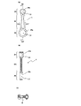
- FIG. 1A is a plan view schematically showing the connecting rod 1.
- 1B is a cross-sectional view taken along line 1B-1B ′ in FIG. 1A, and FIG. 1C is taken along line 1C-1C ′ in FIG. FIG.
- the connecting rod 1 is provided at the rod body 10, the small end 20 provided at one end of the rod body 10, and the other end of the rod body 10.
- the large end 30 is provided.
- the rod body part (shaft part) 10 has a rod shape.
- the cross-sectional shape of the rod body 10 is typically H-shaped as shown in FIG.
- the small end portion 20 has a through hole (piston pin hole) 22 through which the piston pin passes.
- the small end 20 is connected to the piston via a piston pin.
- the inner peripheral surface 20a (surface defining the outer edge of the piston pin hole 22) 20a typically contacts the piston pin without a bearing.
- the large end portion 30 has a through hole (crank pin hole) 32 through which the crank pin passes.
- the large end 30 is connected to the crankshaft via a crankpin. Since a rolling bearing is typically arranged in the crankpin hole 32, the inner peripheral surface 30a (the surface defining the outer edge of the crankpin 32) 30a of the large end 30 is in contact with the rolling bearing.
- the connecting rod 1 is an integrated connecting rod in which the large end portion 30 is not divided into two.
- the connecting rod 1 in this embodiment is formed from an iron alloy.
- the connecting rod 1 is subjected to carbonitriding or carburizing and nitriding.
- the carbon content at a depth of 0.1 mm from the inner peripheral surface 30a of the large end 30 is 0.8 wt% or more and 2.1 wt% or less.
- the high-concentration carbonitriding process or the high-concentration carburizing process fine granular carbides and / or carbonitrides are precipitated in the vicinity of the surface of the connecting rod 1 and the crystal grain size of the martensite structure in the vicinity of the surface is reduced. . Therefore, the surface hardness is remarkably increased, and the effect of improving the fatigue strength is high.
- the nitrogen content at a depth of 0.1 mm from the inner peripheral surface 30a of the large end 30 is 0.03 wt% or more and 0.19 wt% or less. This significantly improves the anti-flaking property.
- FIG. 2 shows the result of calculating the stress distribution in the depth direction (stress distribution when the stress becomes maximum during operation of the internal combustion engine) on the inner peripheral surface of the large end portion of a general connecting rod.
- the depth from the inner peripheral surface is shown as a negative value.
- a position at a depth of 0.15 mm is written as “ ⁇ 0.15”.
- a plurality of curves indicating stress are numbered 1 to 22, and the larger the number, the greater the stress.
- the stress is not the largest on the outermost surface. Further, it can be seen from FIG. 2 that the stress becomes maximum at a depth of about 0.1 mm from the inner peripheral surface. Therefore, the inventor of the present application has examined in detail the relationship between the element concentration at a depth of 0.1 mm and the anti-flaking property. As a result, the nitrogen concentration at the depth of 0.1 mm (nitrogen content) It was found that the flaking property was greatly affected. Specifically, as will be described later together with the verification results, when the nitrogen content at this depth is not less than 0.03 wt% and not more than 0.19 wt%, the effect of improving the anti-flaking property is remarkably increased. I understood.
- the nitrogen content at a depth of 0.1 mm from the inner peripheral surface 30a of the large end portion 30 is 0.03 wt% or more and 0.19 wt% or less, so that the flaking resistance is remarkable. And the occurrence of flaking can be prevented over a long period of time. Therefore, the connecting rod 1 in this embodiment has an excellent fatigue strength compared to a connecting rod that has been simply subjected to high-concentration carbonitriding or high-concentration carburizing.
- the nitrogen content at a depth of 0.1 mm from the inner peripheral surface 30a of the large end 30 is 0.04 wt% or more and 0.18 wt% or less. Preferably, it is 0.05 wt% or more and 0.15 wt% or less.
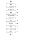
- FIG. 3 is a flowchart showing manufacturing steps of the connecting rod 1.
- a workpiece formed by forging from an iron alloy is prepared (step S1).
- the composition of the iron alloy is not particularly limited, but the carbon (C) content of the iron alloy is preferably 0.1 wt% or more and 0.4 wt% or less.
- the internal hardness (Vickers hardness) of the connecting rod 1 after the heat treatment can be 200 HV or more and 500 HV or less, so the inside of the connecting rod 1 Strength and toughness can be kept sufficiently high.
- the silicon (Si) content of the iron alloy is preferably 0.1 wt% or more and 0.5 wt% or less. Increasing the silicon content improves anti-flaking properties but may reduce toughness. When the silicon content is 0.1 wt% or more and 0.5 wt% or less, the flaking resistance can be sufficiently improved and sufficient toughness can be ensured.
- the chromium content is preferably 0.3 wt% or more and 1.2 wt% or less. Increasing chromium content improves hardenability (property of hardening by heat treatment), but excessive chromium content causes temper embrittlement (the iron alloy is kept in a predetermined temperature range for a long time). The embrittlement phenomenon that occurs when the When the chromium content is 0.3 wt% or more and 1.2 wt% or less, the occurrence of temper embrittlement can be prevented while obtaining appropriate hardenability.
- the iron alloy that is the material of the workpiece is 0.1 wt% or more and 0.4 wt% or less of carbon, 0.1 wt% or more and 0.5 wt% or less of silicon and 0.3 wt%. % Or more and 1.2 wt% or less of chromium is preferable.
- an iron alloy having a carbon content, a silicon content, and a chromium content within the above ranges for example, JIS SCM420 steel or JIS SCr420 steel can be used.
- SCM420 steel is made of 0.18 wt% or more and 0.23 wt% or less of carbon, 0.15 wt% or more and 0.35 wt% or less of silicon, 0.90 wt% or more and 1.2 wt% or less of chromium, 0.60 wt% or more and 0.002 wt% or less. 85% by weight or less of manganese and 0.15% by weight or more and 0.30% or less of molybdenum are included.
- the SCr420 steel is composed of 0.18 wt% or more and 0.23 wt% or less carbon, 0.15 wt% or more and 0.35 wt% or less silicon, 0.90 wt% or more and 1.2 wt% or less chromium, 0.60 wt% or more and 0. Contains 85 wt% or less manganese.
- the nickel content of the iron alloy is preferably as small as possible. Specifically, it is preferably less than 0.7 wt%, and more preferably 0.25 wt% or less. When the nickel content increases, the amount of retained austenite after heat treatment increases, so the surface hardness may decrease.
- molding method in the process of preparing a workpiece is not limited to this.
- the workpiece may be formed by, for example, sintering, casting, sintering forging, or the like.
- step S2 machining is performed on the workpiece (step S2).
- the outer diameter of the workpiece after forging is adjusted. For example, deburring, formation of the piston pin hole 22 and the crank pin hole 32, and end face processing of the small end portion 20 and the large end portion 30 are performed. Thus, cutting is mainly performed in this step.
- step S3 the workpiece is subjected to a first high-concentration carburizing process.
- carburizing methods solid carburizing, liquid carburizing, gas carburizing, etc. are known.
- gas carburizing is the mainstream, but here it is called vacuum carburizing (also called “vacuum gas carburizing” or “vacuum carburizing”).
- vacuum carburizing also called “vacuum gas carburizing” or “vacuum carburizing”.
- the high-concentration carburizing process in this step is performed in a vacuum-evacuated furnace (more specifically, in a furnace whose pressure is reduced to 1/10 or less of the standard atmospheric pressure).
- Such a furnace is set to a temperature higher than the A1 transformation point (eutectoid transformation temperature of steel), and a hydrocarbon gas is introduced into the furnace so that the carbon potential is 0.8% or more, and carburized for a predetermined time.
- a hydrocarbon gas is introduced into the furnace so that the carbon potential is 0.8% or more, and carburized for a predetermined time.
- carburization is performed at 1000 ° C. for 170 minutes.
- the surface of the iron alloy is excessively carburized by the first high-concentration carburizing treatment.
- gas cooling is performed (step S4).
- cooling is performed by introducing nitrogen (N 2) gas.
- step S5 the workpiece is subjected to the second high concentration carburizing process.
- vacuum carburization is performed.
- the inside of the evacuated furnace is set to a temperature not lower than the A1 transformation point and not higher than the Acm transformation point (transformation temperature at which cementite precipitates from the austenite of the iron alloy), and carbonized so that the carbon potential is 0.8% or higher.
- Hydrogen gas is introduced into the furnace and carburized for a predetermined time. For example, carburization is performed at 850 ° C. for 150 minutes. Due to the second high-concentration carburizing treatment, the carbon of the surface layer that has been excessively carburized diffuses inside. Thereafter, gas cooling is performed (step S6).
- nitriding is performed on the workpiece (step S7).
- This nitriding treatment is also performed in a vacuum-evacuated furnace.
- the temperature that was evacuated (specifically, the inside of the furnace reduced to a pressure of 1/10 or less of the standard atmospheric pressure) was set to a temperature not lower than the A1 transformation point and not higher than the Acm transformation point, and ammonia gas was introduced into the furnace.
- nitriding is performed for a predetermined time. For example, carburization is performed at 850 ° C. for 130 minutes. Thereafter, oil cooling (quenching) is performed (step S8).
- step S9 tempering is performed. Tempering is performed at 190 ° C. for 120 minutes, for example. Thereafter, air cooling is performed (step S10).
- step S11 machining is performed on the workpiece (step S11).
- the inner peripheral surface 20a of the small end portion 20 and the inner peripheral surface 30a of the large end portion 30 are polished.
- polishing is mainly performed in this step.
- the connecting rod 1 is completed.
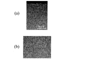
- FIGS. 4A and 4B show the metal structure of the completed connecting rod 1.
- 4A and 4B are metallographic micrographs of a cross section in the vicinity of the surface of the connecting rod 1, and FIG. 4B is an enlarged view of part of FIG. 4A.
- fine granular carbides iron carbide
- carbonitrides iron carbonitride
- FIG. 5 shows the distribution of carbon concentration (carbon content) in the depth direction of the connecting rod 1.
- the carbon concentration at a depth of 0.1 mm from the surface is about 0.92 wt%, and the carbon concentration (carbon content) at this depth is 0. It turns out that it becomes 8 wt% or more.
- the carbon concentration distribution as shown in FIG. 5 can be measured by, for example, an electron beam microanalyzer (EPMA).
- EPMA electron beam microanalyzer
- FIG. 6 shows the hardness distribution in the depth direction of the connecting rod 1. As shown in FIG. 6, the hardness at a depth of 0.1 mm from the surface is about 770 HV.
- the flaking life is a life with a cumulative failure probability of 50% (referred to as “L50 life”).
- Table 1 shows Examples 1 to 4 in which the nitrogen content at a depth of 0.1 mm is in the range of 0.03 wt% to 0.19 wt%, and the nitrogen content at a depth of 0.1 mm. A verification result is shown about the comparative examples 1 and 2 which are outside the range of 0.03 wt% or more and 0.19 wt% or less. Examples 1 to 4 and Comparative Examples 1 and 2 are manufactured by the same manufacturing method except that nitriding conditions are different. Table 1 also shows Comparative Example 3 in which ordinary carburizing treatment (carburizing treatment other than high-concentration carburizing treatment) was performed as a conventional connecting rod, and high-concentration carburizing treatment as disclosed in Patent Document 1. 6 is shown together with Comparative Example 4 to which is applied. The distribution of the nitrogen content in the depth direction can be measured by, for example, an electron beam microanalyzer (EPMA).
- EPMA electron beam microanalyzer
- the nitrogen content at the surface layer and at a depth of 0.2 mm does not have a clear correlation with the flaking life.
- Comparative Example 1 although the nitrogen content in the surface layer is significantly higher than those in Comparative Examples 3 and 4, only the same flaking life as that in the prior art can be obtained.
- Examples 1 and 3 although the nitrogen content at the position of a depth of 0.2 mm is almost the same as that in Comparative Examples 3 and 4, a flaking life longer than that in the prior art is obtained.
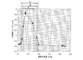
- FIG. 7 is a graph showing the relationship between the nitrogen content at a depth of 0.1 mm and the flaking life (L50 life).
- the graph of FIG. 7 shows more examples than the example shown in Table 1.
- a flaking life longer than the conventional one is realized when the nitrogen content at a depth of 0.1 mm from the surface is 0.03 wt% or more and 0.19 wt% or less (range A in FIG. 7). You can see that Further, from FIG. 7, a longer flaking life is realized when the nitrogen content at a depth of 0.1 mm from the surface is 0.04 wt% or more and 0.18 wt% or less (range B in FIG. 7). , 0.05 wt% or more and 0.15 wt% or less (range C in FIG. 7), it can be seen that a longer flaking life is realized.
- the connecting rod 1 may be subjected to a high concentration carbonitriding process.
- FIG. 8 the example of the manufacturing process of the connecting rod 1 in the case of performing a high concentration carbonitriding process is shown.
- step S1 a workpiece formed by forging from an iron alloy is prepared (step S1), and then machining (mainly cutting) is performed on the workpiece (step S2). Subsequently, a high-concentration carburizing process is performed on the workpiece in a vacuum-evacuated furnace (step S3), and then gas cooling is performed (step S4).
- step S5 a high concentration carbonitriding process is performed on the workpiece in a vacuum-evacuated furnace.
- High concentration carbonitriding is performed by introducing ammonia gas together with hydrocarbon gas into the furnace.
- oil cooling quenching
- step S7 tempering is performed (step S7), and then air cooling is performed (step S8). Finally, machining (mainly polishing) is performed on the workpiece (step S9). As described above, the connecting rod 1 is completed.
- the high-concentration carburizing treatment (steps S3 and S5 in FIG. 3 and the step S3 in FIG. 8) and the high-concentration carbonitriding treatment (step S5 in FIG. 8) are performed in the vacuum-evacuated furnace as described above. (That is, vacuum carburizing or vacuum carbonitriding).
- gas cooling can be performed as a subsequent heat treatment instead of furnace cooling or quenching, so that the processing time can be shortened.
- nitriding treatment (step S7 in FIG. 3) and high concentration carbonitriding treatment (Step S5 in FIG. 8) is preferably performed in a vacuum-evacuated furnace.
- a nitrogen-containing gas for example, ammonia gas
- the nitrogen content at a depth of 0.1 mm from the surface can be accurately adjusted.
- FIG. 9 shows the nitrogen content at a depth of 0.1 mm from the surface when nitriding or high-concentration carbonitriding is performed in a gas carburizing furnace and in a vacuum carburizing furnace. Shows the relationship with time.
- the appropriate nitriding time range C when processing in a gas carburizing furnace is significantly greater than the appropriate nitriding time range D when processing in a vacuum carburizing furnace. It is very difficult to actually keep the nitriding time within this range C. Since the technique disclosed in Patent Document 1 is premised on gas carburization, the nitrogen content at a depth of 0.1 mm from the surface can be reduced even when the high-concentration carbonitriding process taught in Patent Document 1 is used. It cannot be within the range of 0.03 wt% or more and 0.19 wt% or less.
- the particle size (more specifically, circumscribed circle diameter) of carbides and carbonitrides precipitated in the vicinity of the inner peripheral surface 30a of the large end portion 30 is It is preferably as small as possible, specifically 10 ⁇ m or less.
- the particle size of the carbide and carbonitride exceeds 10 ⁇ m, the toughness may be lowered and sufficient strength may not be obtained.
- the rod main body part 10 has higher toughness than the large end part 30, the rod main body part before the first high-concentration carburizing process (step S3 in FIG. 3 and step S3 in FIG. 8). 10 may be masked with copper plating or a carbon-proofing agent.
- the toughness of the rod body 10 can be increased.
- the local tempering can be performed by, for example, high frequency induction heating.
- the high-concentration carburization process is performed twice as shown in FIG. 3 and the high-concentration carburization process and the high-concentration carbonitriding process are performed once each as shown in FIG.
- the high-concentration carburizing process and / or the high-concentration carbonitriding process may be performed three or more times in total.
- non-diffusible hydrogen content of the connecting rod 1 has a great influence on the flaking life.
- Hydrogen in the iron alloy is classified into two types depending on its solid solution state. Hydrogen that diffuses at room temperature is called diffusible hydrogen, and hydrogen that is trapped by inclusions and the like and hardly diffuses at temperatures from room temperature to about 200 ° is called non-diffusible hydrogen.
- the non-diffusible hydrogen content is preferably 0.46 ppm or less. Since the non-diffusible hydrogen content is 0.46 ppm or less, the occurrence of hydrogen brittle mold peeling can be suppressed, so that the flaking life can be further improved.
- Table 2 shows the non-diffusible hydrogen content for Examples 1 to 4 and Comparative Examples 1 to 4 shown in Table 1.
- Table 2 also shows the non-diffusible hydrogen content for further Examples 5-7.
- the nitrogen content at a depth of 0.1 mm is in the range of 0.03 wt% or more and 0.19 wt% or less.
- Table 2 also shows whether the carburizing process (or carbonitriding process) in each example is gas carburizing (gas carbonitriding) or vacuum carburizing (vacuum carbonitriding). Note that the measurement of the non-diffusible hydrogen content was performed by a temperature rising desorption method. The test piece was gradually heated from 200 ° C. to 600 ° C., and the amount of hydrogen released from the test piece was quantitatively analyzed by a mass spectrometer.
- Example 4 From the comparison between Example 4 and Example 6 in Table 2 or the comparison between Example 5 and Example 7, even if the nitrogen content at the depth of 0.1 mm is the same, non-diffusible hydrogen It can be seen that the smaller the content, the longer the flaking life, and the non-diffusible hydrogen content is preferably 0.46 ppm or less.
- the non-diffusible hydrogen content is less when the carburizing process (carbonitriding process) is vacuum carburizing (vacuum carbonitriding) than when gas carburizing (gas carbonitriding). From this point, it can be seen that vacuum carburization (vacuum carbonitriding) is preferable.
- the connecting rod 1 in the present embodiment is suitably used for a single cylinder internal combustion engine having one cylinder.
- FIG. 10 shows an example of a single cylinder internal combustion engine 100 provided with the connecting rod 1 in the present embodiment.
- the internal combustion engine 100 includes a crankcase 110, a cylinder block 120, and a cylinder head 130.
- crankshaft 111 is accommodated in the crankcase 110.
- the crankshaft 111 has a crankpin 112 and a crank web 113.
- the crank pin 112 and the crank web 113 are formed separately. That is, the crankshaft 111 is an assembly-type crankshaft.
- a cylinder block 120 is provided on the crankcase 110.
- the cylinder block 120 is fitted with a cylindrical cylinder sleeve 121, and the piston 122 is provided so as to reciprocate within the cylinder sleeve 121.
- a cylinder head 130 is provided on the cylinder block 120.
- the cylinder head 130 forms a combustion chamber 131 together with the piston 122 and the cylinder sleeve 121 of the cylinder block 120.
- the cylinder head 130 has an intake port 132 and an exhaust port 133.
- An intake valve 134 for supplying air-fuel mixture into the combustion chamber 131 is provided in the intake port 132, and an exhaust valve 135 for exhausting the combustion chamber 131 is provided in the exhaust port 133. Yes.
- the piston 122 and the crankshaft 111 are connected by the connecting rod 1. Specifically, the piston pin 123 of the piston 122 is inserted into the piston pin hole formed in the small end portion 20 of the connecting rod 1, and the crankshaft 111 is formed in the crankpin hole formed in the large end portion 30. The crank pin 112 is inserted, whereby the piston 122 and the crank shaft 111 are connected.
- a needle bearing 114 is provided between the inner peripheral surface 30a of the large end 30 of the connecting rod 1 and the crank pin 112. Is provided.
- the needle bearing 114 When the needle bearing 114 is provided, stress is generated on the inner peripheral surface 30 a of the large end portion 30 by pressing the connecting rod 1 against the needle bearing 114. If this stress is excessive, the occurrence of flaking is a concern.
- the connecting rod 1 in this embodiment is excellent in anti-flaking property, the occurrence of flaking is prevented for a long period of time longer than that required for a product.
- crankpin 112 is preferably subjected to carburizing or carbonitriding.
- the needle bearing 114 is illustrated as the rolling bearing, but the rolling bearing is not limited to a roller bearing such as a needle bearing, and may be a ball bearing (ball bearing).
- FIG. 11 shows a motorcycle including the internal combustion engine 100 shown in FIG.
- a head pipe 302 is provided at the front end of the main body frame 301.
- a front fork 303 is attached to the head pipe 302 so as to be able to swing in the left-right direction of the vehicle.
- a front wheel 304 is rotatably supported at the lower end of the front fork 303.
- a seat rail 306 is attached so as to extend rearward from the upper rear end of the main body frame 301.
- a fuel tank 307 is provided on the main body frame 301, and a main seat 308 a and a tandem seat 308 b are provided on the seat rail 306.
- a rear arm 309 extending backward is attached to the rear end of the main body frame 301.
- a rear wheel 310 is rotatably supported at the rear end of the rear arm 309.
- the internal combustion engine 100 shown in FIG. 10 is held at the center of the main body frame 301.
- the internal combustion engine 100 includes the connecting rod 1 in the present embodiment.
- a radiator 311 is provided in front of the internal combustion engine 100.
- An exhaust pipe 312 is connected to the exhaust port of the internal combustion engine 100, and a muffler 313 is attached to the rear end of the exhaust pipe 312.
- a transmission 315 is connected to the internal combustion engine 100.
- a drive sprocket 317 is attached to the output shaft 316 of the transmission 315.
- the drive sprocket 317 is connected to the rear wheel sprocket 319 of the rear wheel 310 via a chain 318.
- the transmission 315 and the chain 318 function as a transmission mechanism that transmits the power generated by the internal combustion engine 100 to the drive wheels.
- the connecting rod 1 in the present embodiment is also suitable for reducing the size and weight. This is because it is possible to apply a high load to the connecting rod 1 by extending the life.
- the internal combustion engine 100 and the vehicle body are also lightened, and the running stability, ease of riding, and ease of handling of the motorcycle are improved, and the merchantability is improved.
- the internal combustion engine 100 provided with the connecting rod 1 in the present embodiment is not limited to a motorcycle, and is preferably used for all saddle riding type vehicles on which riders ride. For example, it is also used for ATV such as buggy.
- connecting rod 1 in the present embodiment can also be used for a small internal combustion engine used in a generator, an agricultural machine, or the like.
- the connecting rod according to the present invention is widely used in internal combustion engines for various straddle-type vehicles (for example, internal combustion engines for motorcycles).
Landscapes
- Chemical & Material Sciences (AREA)
- Engineering & Computer Science (AREA)
- Mechanical Engineering (AREA)
- Organic Chemistry (AREA)
- Materials Engineering (AREA)
- Metallurgy (AREA)
- Physics & Mathematics (AREA)
- Thermal Sciences (AREA)
- Crystallography & Structural Chemistry (AREA)
- General Engineering & Computer Science (AREA)
- Chemical Kinetics & Catalysis (AREA)
- Shafts, Cranks, Connecting Bars, And Related Bearings (AREA)
- Solid-Phase Diffusion Into Metallic Material Surfaces (AREA)
- Heat Treatment Of Articles (AREA)
Abstract
Description


10 ロッド本体部
20 小端部
20a 小端部の内周面
22 ピストンピン孔
30 大端部
30a 大端部の内周面
32 クランクピン孔
100 単気筒内燃機関
Claims (17)
- ロッド本体部と、
前記ロッド本体部の一端に設けられた小端部と、
前記ロッド本体部の他端に設けられた大端部と、を備え、
鉄合金から形成され、
浸炭窒化処理が施されたか、または、浸炭処理および窒化処理が施されたコネクティングロッドであって、
前記大端部の内周面から0.1mmの深さにおける炭素含有量が0.8wt%以上2.1wt%以下であり、
前記大端部の内周面から0.1mmの深さにおける窒素含有量が0.03wt%以上0.19wt%以下であるコネクティングロッド。 - 前記大端部の内周面から0.1mmの深さにおける窒素含有量が0.04wt%以上0.18wt%以下である請求項1に記載のコネクティングロッド。
- 前記大端部の内周面から0.1mmの深さにおける窒素含有量が0.05wt%以上0.15wt%以下である請求項1に記載のコネクティングロッド。
- 前記鉄合金は、0.1wt%以上0.4wt%以下の炭素、0.1wt%以上0.5wt%以下のケイ素および0.3wt%以上1.2wt%以下のクロムを含む請求項1から3のいずれかに記載のコネクティングロッド。
- 前記鉄合金のニッケル含有量は0.7wt%未満である請求項1から4のいずれかに記載のコネクティングロッド。
- 非拡散性水素含有量が0.46ppm以下である請求項1から5のいずれかに記載のコネクティングロッド。
- 前記浸炭窒化処理、前記浸炭処理および前記窒化処理は、標準大気圧の1/10以下の圧力に減圧された炉内において施されている請求項1から6のいずれかに記載のコネクティングロッド。
- 前記大端部の内周面近傍に析出している炭化物および炭窒化物の粒径が10μm以下である請求項1から7のいずれかに記載のコネクティングロッド。
- 請求項1から8のいずれかに記載のコネクティングロッドと、
前記コネクティングロッドに接続されたクランクシャフトと、
を備える単気筒内燃機関。 - 前記クランクシャフトは、前記コネクティングロッドの前記大端部に挿通されたクランクピンと、前記クランクピンとは別体に形成されたクランクウェブと、を有する請求項9に記載の単気筒内燃機関。
- 前記大端部の内周面と前記クランクピンとの間に設けられた転がり軸受けをさらに備える請求項10に記載の単気筒内燃機関。
- 前記クランクピンは、浸炭処理または浸炭窒化処理を施されている請求項11に記載の単気筒内燃機関。
- 請求項9から12のいずれかに記載の単気筒内燃機関を備えた鞍乗型車両。
- ロッド本体部、前記ロッド本体部の一端部に設けられた小端部および前記ロッド本体部の他端部に設けられた大端部を備えるコネクティングロッドの製造方法であって、
鉄合金から形成されたワークピースを用意する工程(A)と、
前記ワークピースに対して0.8%以上のカーボンポテンシャルを有する雰囲気下で浸炭処理を施す工程(B)と、
前記工程(B)の後に、前記ワークピースに対して0.8%以上のカーボンポテンシャルを有する雰囲気下で浸炭窒化処理を施す工程(C)と、を包含し、
前記工程(C)は、前記ワークピースの前記大端部となる領域の内周面から0.1mmの深さにおける窒素含有量が0.03wt%以上0.19wt%以下となるように実行されるコネクティングロッドの製造方法。 - 前記工程(B)における前記浸炭処理および前記工程(C)における前記浸炭窒化処理は、標準大気圧の1/10以下の圧力に減圧された炉内において施される請求項14に記載のコネクティングロッドの製造方法。
- ロッド本体部、前記ロッド本体部の一端部に設けられた小端部および前記ロッド本体部の他端部に設けられた大端部を備えるコネクティングロッドの製造方法であって、
鉄合金から形成されたワークピースを用意する工程(A)と、
前記ワークピースに対して0.8%以上のカーボンポテンシャルを有する雰囲気下で複数回浸炭処理を施す工程(B)と、
前記工程(B)の後に、前記ワークピースに対して窒化処理を施す工程(C)と、を包含し、
前記工程(C)は、前記ワークピースの前記大端部となる領域の内周面から0.1mmの深さにおける窒素含有量が0.03wt%以上0.19wt%以下となるように実行されるコネクティングロッドの製造方法。 - 前記工程(B)における前記浸炭処理および前記工程(C)における前記窒化処理は、標準大気圧の1/10以下の圧力に減圧された炉内において施される請求項16に記載のコネクティングロッドの製造方法。
Priority Applications (2)
| Application Number | Priority Date | Filing Date | Title |
|---|---|---|---|
| JP2011547427A JP5342655B2 (ja) | 2009-12-24 | 2010-11-30 | コネクティングロッドおよびそれを備えた単気筒内燃機関ならびに鞍乗型車両 |
| PH1/2012/501266A PH12012501266A1 (en) | 2009-12-24 | 2010-11-30 | Connecting rod, single-cylinder internal combustion engine comprising same, and saddle type vehicle |
Applications Claiming Priority (2)
| Application Number | Priority Date | Filing Date | Title |
|---|---|---|---|
| JP2009-292676 | 2009-12-24 | ||
| JP2009292676 | 2009-12-24 |
Publications (1)
| Publication Number | Publication Date |
|---|---|
| WO2011077904A1 true WO2011077904A1 (ja) | 2011-06-30 |
Family
ID=44195443
Family Applications (1)
| Application Number | Title | Priority Date | Filing Date |
|---|---|---|---|
| PCT/JP2010/071328 Ceased WO2011077904A1 (ja) | 2009-12-24 | 2010-11-30 | コネクティングロッドおよびそれを備えた単気筒内燃機関ならびに鞍乗型車両 |
Country Status (4)
| Country | Link |
|---|---|
| JP (1) | JP5342655B2 (ja) |
| MY (1) | MY160847A (ja) |
| PH (1) | PH12012501266A1 (ja) |
| WO (1) | WO2011077904A1 (ja) |
Cited By (3)
| Publication number | Priority date | Publication date | Assignee | Title |
|---|---|---|---|---|
| JP2015010250A (ja) * | 2013-06-27 | 2015-01-19 | 愛知製鋼株式会社 | 減圧浸炭浸窒処理方法 |
| WO2018235962A1 (ja) * | 2017-06-23 | 2018-12-27 | 新日鐵住金株式会社 | 高強度鋼部材 |
| KR20210092773A (ko) * | 2018-11-14 | 2021-07-26 | 징란 왕 | 연자성 금속 재료의 처리 방법 |
Citations (3)
| Publication number | Priority date | Publication date | Assignee | Title |
|---|---|---|---|---|
| JPH1046286A (ja) * | 1996-07-26 | 1998-02-17 | Nippon Seiko Kk | 転がり軸受 |
| JP2000313949A (ja) * | 1999-04-27 | 2000-11-14 | Yamaha Motor Co Ltd | 鉄合金部品の表面硬化処理方法 |
| JP2009019639A (ja) * | 2003-02-28 | 2009-01-29 | Ntn Corp | エンジンのローラ付きカムフォロアの製造方法 |
Family Cites Families (5)
| Publication number | Priority date | Publication date | Assignee | Title |
|---|---|---|---|---|
| JP2000310329A (ja) * | 1999-04-28 | 2000-11-07 | Yamaha Motor Co Ltd | 表面硬化処理したコンロッド |
| JP5306795B2 (ja) * | 2008-12-24 | 2013-10-02 | ヤマハ発動機株式会社 | コンロッド、内燃機関、輸送機器およびコンロッドの製造方法 |
| JP2010151218A (ja) * | 2008-12-25 | 2010-07-08 | Yamaha Motor Co Ltd | コンロッド、内燃機関、輸送機器およびコンロッドの製造方法 |
| MY185935A (en) * | 2011-02-14 | 2021-06-14 | Yamaha Motor Co Ltd | Steel part, single-cylinder internal combustion engine, saddled vehicle, and process for manufacture of steel part |
| JP2012255551A (ja) * | 2012-07-05 | 2012-12-27 | Yamaha Motor Co Ltd | コンロッドの製造方法 |
-
2010
- 2010-11-30 PH PH1/2012/501266A patent/PH12012501266A1/en unknown
- 2010-11-30 MY MYPI2012700388A patent/MY160847A/en unknown
- 2010-11-30 WO PCT/JP2010/071328 patent/WO2011077904A1/ja not_active Ceased
- 2010-11-30 JP JP2011547427A patent/JP5342655B2/ja active Active
Patent Citations (3)
| Publication number | Priority date | Publication date | Assignee | Title |
|---|---|---|---|---|
| JPH1046286A (ja) * | 1996-07-26 | 1998-02-17 | Nippon Seiko Kk | 転がり軸受 |
| JP2000313949A (ja) * | 1999-04-27 | 2000-11-14 | Yamaha Motor Co Ltd | 鉄合金部品の表面硬化処理方法 |
| JP2009019639A (ja) * | 2003-02-28 | 2009-01-29 | Ntn Corp | エンジンのローラ付きカムフォロアの製造方法 |
Cited By (9)
| Publication number | Priority date | Publication date | Assignee | Title |
|---|---|---|---|---|
| JP2015010250A (ja) * | 2013-06-27 | 2015-01-19 | 愛知製鋼株式会社 | 減圧浸炭浸窒処理方法 |
| WO2018235962A1 (ja) * | 2017-06-23 | 2018-12-27 | 新日鐵住金株式会社 | 高強度鋼部材 |
| CN110651061A (zh) * | 2017-06-23 | 2020-01-03 | 日本制铁株式会社 | 高强度钢构件 |
| JPWO2018235962A1 (ja) * | 2017-06-23 | 2020-03-26 | 日本製鉄株式会社 | 高強度鋼部材 |
| EP3643803A4 (en) * | 2017-06-23 | 2020-10-28 | Nippon Steel Corporation | HIGHLY RESISTANT STEEL ELEMENT |
| KR20210092773A (ko) * | 2018-11-14 | 2021-07-26 | 징란 왕 | 연자성 금속 재료의 처리 방법 |
| JP2022510734A (ja) * | 2018-11-14 | 2022-01-27 | 王静然 | 軟磁性金属材料の処理方法 |
| US12071695B2 (en) | 2018-11-14 | 2024-08-27 | Jingran WANG | Method for increasing magnetic induction intensity of soft magnetic metallic materials |
| KR102718191B1 (ko) * | 2018-11-14 | 2024-10-17 | 징란 왕 | 연자성 금속 재료의 처리 방법 |
Also Published As
| Publication number | Publication date |
|---|---|
| JPWO2011077904A1 (ja) | 2013-05-02 |
| PH12012501266A1 (en) | 2012-11-05 |
| JP5342655B2 (ja) | 2013-11-13 |
| MY160847A (en) | 2017-03-31 |
Similar Documents
| Publication | Publication Date | Title |
|---|---|---|
| WO2006013696A1 (ja) | ロッカーアーム用転がり軸受 | |
| US20110308227A1 (en) | Method for producing a control chain | |
| US8479704B2 (en) | Sliding component for internal combustion engine, internal combustion engine, transporter, and method for producing the sliding component for internal combustion engine | |
| JP5306795B2 (ja) | コンロッド、内燃機関、輸送機器およびコンロッドの製造方法 | |
| JP2009215597A (ja) | 転動部品及びその製造方法 | |
| JP5342655B2 (ja) | コネクティングロッドおよびそれを備えた単気筒内燃機関ならびに鞍乗型車両 | |
| JP4166041B2 (ja) | 焼結スプロケット及びその製造方法 | |
| JP2018141218A (ja) | 部品およびその製造方法 | |
| JP2018141216A (ja) | 部品およびその製造方法 | |
| JP5603889B2 (ja) | 鋼製部品、単気筒内燃機関、鞍乗型車両および鋼製部品の製造方法 | |
| JP4301507B2 (ja) | サイレントチェーン用焼結スプロケットおよびその製造方法 | |
| JP2009228829A (ja) | 軸棒の製造方法、軸受の製造方法、軸棒および軸受 | |
| JP2019056141A (ja) | 浸炭窒化用鋼材および浸炭窒化軸受部品 | |
| JP4870922B2 (ja) | コンロッド、エンジン、自動車両およびコンロッドの製造方法 | |
| JP2004538423A (ja) | 内燃機関用の燃料噴射弁及び該燃料噴射弁の焼入れ法 | |
| JP5744000B2 (ja) | 内燃機関用摺動部品、内燃機関、輸送機器および内燃機関用摺動部品の製造方法 | |
| JP5433692B2 (ja) | コネクティングロッド、内燃機関、輸送機器およびコネクティングロッドの製造方法 | |
| JP2003277882A (ja) | 鉄合金部品およびその製造方法 | |
| JP2019157880A (ja) | コンロッド、内燃機関およびコンロッドの製造方法 | |
| JP2010151218A (ja) | コンロッド、内燃機関、輸送機器およびコンロッドの製造方法 | |
| US7621244B2 (en) | Titanium alloy tappet, manufacturing method thereof, and jig used in manufacturing tappet | |
| JP5207236B2 (ja) | 軸棒の製造方法、軸受の製造方法、軸棒および軸受 | |
| JP2018141217A (ja) | 部品およびその製造方法 | |
| WO2017170435A1 (ja) | 製造性と耐水素脆性に優れた耐環境用軸受鋼 | |
| EP3015723A1 (en) | Connecting rod, internal combustion engine, automotive vehicle, and production method for connecting rod |
Legal Events
| Date | Code | Title | Description |
|---|---|---|---|
| 121 | Ep: the epo has been informed by wipo that ep was designated in this application |
Ref document number: 10839139 Country of ref document: EP Kind code of ref document: A1 |
|
| WWE | Wipo information: entry into national phase |
Ref document number: 2011547427 Country of ref document: JP |
|
| WWE | Wipo information: entry into national phase |
Ref document number: 12012501266 Country of ref document: PH |
|
| WWE | Wipo information: entry into national phase |
Ref document number: 1201003028 Country of ref document: TH |
|
| NENP | Non-entry into the national phase |
Ref country code: DE |
|
| 122 | Ep: pct application non-entry in european phase |
Ref document number: 10839139 Country of ref document: EP Kind code of ref document: A1 |