WO2011077604A1 - 壁パネル - Google Patents
壁パネル Download PDFInfo
- Publication number
- WO2011077604A1 WO2011077604A1 PCT/JP2010/004150 JP2010004150W WO2011077604A1 WO 2011077604 A1 WO2011077604 A1 WO 2011077604A1 JP 2010004150 W JP2010004150 W JP 2010004150W WO 2011077604 A1 WO2011077604 A1 WO 2011077604A1
- Authority
- WO
- WIPO (PCT)
- Prior art keywords
- screw
- wall panel
- folded plate
- face material
- bearing
- Prior art date
- Legal status (The legal status is an assumption and is not a legal conclusion. Google has not performed a legal analysis and makes no representation as to the accuracy of the status listed.)
- Ceased
Links
Images























Classifications
-
- E—FIXED CONSTRUCTIONS
- E04—BUILDING
- E04C—STRUCTURAL ELEMENTS; BUILDING MATERIALS
- E04C2/00—Building elements of relatively thin form for the construction of parts of buildings, e.g. sheet materials, slabs, or panels
- E04C2/30—Building elements of relatively thin form for the construction of parts of buildings, e.g. sheet materials, slabs, or panels characterised by the shape or structure
- E04C2/38—Building elements of relatively thin form for the construction of parts of buildings, e.g. sheet materials, slabs, or panels characterised by the shape or structure with attached ribs, flanges, or the like, e.g. framed panels
- E04C2/384—Building elements of relatively thin form for the construction of parts of buildings, e.g. sheet materials, slabs, or panels characterised by the shape or structure with attached ribs, flanges, or the like, e.g. framed panels with a metal frame
-
- E—FIXED CONSTRUCTIONS
- E04—BUILDING
- E04C—STRUCTURAL ELEMENTS; BUILDING MATERIALS
- E04C2/00—Building elements of relatively thin form for the construction of parts of buildings, e.g. sheet materials, slabs, or panels
- E04C2/02—Building elements of relatively thin form for the construction of parts of buildings, e.g. sheet materials, slabs, or panels characterised by specified materials
- E04C2/08—Building elements of relatively thin form for the construction of parts of buildings, e.g. sheet materials, slabs, or panels characterised by specified materials of metal, e.g. sheet metal
Definitions
- the present invention relates to a wall panel used in a building such as a thin plate lightweight steel structure.
- the folded plate and the frame member are rigidly joined such that the folded plate is welded to the frame member or fixed to the frame member through a reinforcing member.
- the frame material itself also forms a rigid frame and is fixed to a building frame such as a beam.
- Such a load-bearing wall is configured such that when a horizontal force such as an earthquake acts on a building, the folded plate bears a shearing force to ensure the horizontal strength of the building. Therefore, the retained horizontal strength of the building is determined based on the shear strength of the folded plate.
- Patent Document 3 proposes that a folded plate is screwed to a vertical frame and the folded plate is also used as a reinforcing material for the vertical frame. Furthermore, in Patent Document 3, a folded plate is effective as a steel plate face material for preventing deformation of a frame material made of a thin lightweight steel, and further, by arranging joints in an orthogonal direction with respect to the frame material, It is described that the bearing wall is excellent in yield strength and deformation performance.
- Patent Document 4 avoids the overall buckling and local buckling of the face material so as to cause the bearing material to deform under pressure at the screw joint. It has a folded plate shape.
- the screw head is enlarged so that the screw does not come out of the long hole formed by the bearing deformation of the screw hole, and so that local deformation (flaw) around the screw hole does not occur. It has been proposed that the screw shaft diameter should not be too large.
- the present invention aims to solve the above-mentioned problems and to provide a wall panel that can stably secure a supporting pressure deformation of a screw joint portion in a folded plate and has excellent deformation performance.
- the present invention employs the following means in order to solve the above problems and achieve the object. That is, (1)
- the wall panel of the present invention has a pair of frame members arranged opposite to each other with a space between them; fixed to these frame members, and crests and troughs are alternately formed from one to the other.
- a surface material that is a folded plate of a thin steel plate; and a screw that fixes a valley portion of the surface material to each frame material; and when the in-plane shear force acts on each frame material,
- a wall panel for a load bearing wall in which the surrounding portion of the screw is resisted by bearing deformation, and the ratio of the screw withdrawal resistance to the bearing load resistance of the face material is the The shaft portion is set to a predetermined value that is inclined.
- the predetermined value may be 0.7 or more.
- the predetermined value may be 1.6 or less.
- the wall panel of the present invention described in (1) or (2) further includes a washer into which a screw is inserted, and a ratio obtained by dividing the outer diameter of the washer by the shaft diameter of the shaft portion of the screw. However, it may be 3.0 or more.
- the predetermined value may be 4.0 or less.
- the frame member is arranged in a direction orthogonal to the first frame member arranged in the extending direction of the valley part and the extending direction of the valley part.
- a square frame is formed by the first frame member and the second frame member, and a washer is inserted only in a screw that fixes the first frame member to the valley portion of the face member. May be.
- a gap may be formed between the hole of the washer and the shaft portion of the screw.
- the ratio obtained by dividing the difference obtained by subtracting the shaft diameter of the screw shaft from the inner diameter of the washer by the thickness of the washer is 0.1 to It may be 0.6.
- the breaking elongation of the face material may be 1% or more and less than 16%.
- the pitch of the screw threads may be equal to or less than the thickness of each frame member.
- the yield ratio of the face material may be 77% to 96%.
- At least one side of the face material along the extending direction of the valley portion is centered on the screw hole through which the shaft portion of the screw is inserted. Ribs that are orthogonal to the extending direction may be further provided.
- the wall panel of the present invention described in the above (1), since the ratio of the screw proof stress to the bearing proof strength of the face material is set to a predetermined value, the rapid proof strength due to screw detachment is set. The decrease can be suppressed. Thereby, the screw periphery of a face material can be stably plastically deformed, and the energy generated in the composition surface can be absorbed. Further, it is possible to prevent a sudden decrease in the proof stress of the load bearing wall as compared with the conventional load bearing wall after improving the deformation performance of the face material. As a result, the wall panel is excellent in deformation performance. Further, by utilizing the inclination of the shaft portion of the screw, the plasticized face material gathered in the vicinity of the screw gathers at the tip portion of the screw hole and is easily crushed and eliminated.
- the tip of the screw is a frame material before the screw is inclined. Can be prevented from coming off.
- the screw since the ratio of the screw pull-out proof strength to the bearing proof strength of the face material is 1.6 or less, the screw (particularly, the head of the screw) is the face material. The screw can be tilted without going underneath.
- the screw (especially the head of the screw) is placed under the face material by arranging the washer so as to overlap the range in which the stress around the screw is largely applied.
- the screw can be tilted without being submerged.
- the screw head does not sink under the face material. Even if the deformation progresses, the face material can exhibit a stable bearing strength.
- the wall panel of the present invention described in (5) above by using a washer, the upper limit of the ratio of the unscrewing strength of the screw to the bearing strength of the face material can be relaxed.
- the screw when the predetermined value is 4.0 or less, the screw can maintain the yield strength, and the screw can be inclined without being submerged under the face material. Further, when a square frame is formed by the first frame member and the second frame member, the square frame is fixed to the first frame member as compared with the bearing deformation of the face member fixed to the second frame member. The bearing deformation of the face material is greater. Therefore, according to the wall panel of the present invention described in the above (6), since the washer is inserted only into the screw that fixes the face material to the first frame member, the screw (particularly, the head of the screw). ) Can be suppressed from entering under the face material, and the assembly process and the number of parts can be reduced. That is, the overall production cost can be suppressed while stably securing the supporting pressure deformation around the screw in the face material.
- the screw is inclined using this gap.
- the screw is inclined at an appropriate inclination angle by defining the inner diameter dimension of the washer, the axial diameter dimension of the shaft portion of the screw, and the thickness dimension of the washer. be able to.
- the breaking elongation of the face material is 1% or more and less than 16%.
- the plasticized portion of the face material around the screw supported by the screw is easily crushed and eliminated.
- the face material can be stably plastically deformed. Furthermore, stable proof stress and deformation performance can be exhibited.
- high YR steel having a yield ratio of 77% to 96% is used as the face material, not low YR (yield ratio) steel.
- the plasticizing region in the case where the periphery of the screw hole of the face material is plastically deformed by the bearing pressure of the screw shaft portion can be narrowed. Therefore, since the hole width of the screw hole into which the screw is inserted is not extremely widened, the screw (particularly, the head of the screw) can be prevented from entering the face material, and the load bearing wall is greatly deformed by shear deformation. Even so, the proof stress of the load bearing wall can be stabilized.
- the rib can prevent local buckling in the direction orthogonal to the direction in which the folded plate is plasticized, and the predetermined direction of the bearing wall
- the face material can be plasticized.
- the wall panel of the present invention described in (13) above, when the screw periphery of the folded plate is plasticized with screws, the thin plate portion is plasticized.
- wrinkles can be prevented from occurring in the face material by limiting the plasticizing range to a specific place.
- a wrinkle indicates, for example, local out-of-plane buckling.
- the strength-decreasing portion is plasticized.
- the proof stress of the load bearing wall can be stabilized even when the face material is greatly deformed.
- FIG. 1st Embodiment of this invention It is a front view which shows the wall panel applied to the load-bearing wall of 1st Embodiment of this invention. It is a side view of the same wall panel of FIG. It is the sectional view on the AA line of the same wall panel of FIG. It is a schematic perspective view of the same wall panel shown in FIG. It is a partial expansion perspective view of the edge part of the same wall panel shown in FIG. It is explanatory drawing which shows the destruction mode in the screw junction part of the same wall panel. It is explanatory drawing which shows the destruction mode in the screw junction part of the same wall panel. It is explanatory drawing which shows the destruction mode in the screw junction part of the same wall panel. It is explanatory drawing which shows the destruction mode in the screw junction part of the same wall panel. It is explanatory drawing which shows the destruction mode in the screw junction part of the same wall panel. It is explanatory drawing which shows the destruction mode in the screw junction part of the same wall panel.
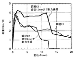
- FIG. 7B is a diagram comparing envelopes of a load-displacement relationship obtained by an element test of the screw joint portion of the folded plate shown in FIG. 7A.
- FIG. 7B is a diagram comparing envelopes of a load-displacement relationship obtained by an element test of the screw joint portion of the folded plate shown in FIG. 7A.
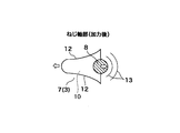
- FIG. 10B It is a fragmentary sectional view in case a screw inclines with respect to a folded plate with small breaking elongation. It is a perspective view of the plasticizing part of the folded plate in FIG. 10D. It is sectional drawing of the screw joint part which has joined the frame material and the face material in the state in which the screw inclined.
- FIG. 11B is a cross-sectional view showing the relationship between the screw diameter and the thickness dimension of the outermost edge of the face material in the BB cross section of FIG. 11A.
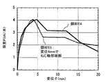
- FIG. 16 is a graph comparing envelopes of load-displacement relationships obtained in the element test shown in FIGS. 15A to 15D.
- FIG. FIG. 16 is a graph comparing envelopes of load-displacement relationships obtained in the element test shown in FIGS. 15A to 15D.
- FIG. 16 is a graph comparing the load-displacement envelopes obtained in the same element test shown in FIGS. 15A to 15D.
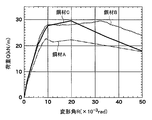
- FIG. It is a front view which shows the dimension shape of the test body used by the proof stress test of a wall panel. It is a graph which shows the load-deformation angle relationship obtained by the proof stress test using the test body shown in FIG. It is sectional drawing for demonstrating the relationship between the screw thread pitch of a screw, and the detachment
- FIG. 24B is a front view showing a state where the face material is plastically deformed in a state where the frame material and the face material are deviated from the state of FIG.
- FIG. 24A is a figure corresponding to Drawing 24A, and is a front view showing the state where support pressure is acting on a face material of high YR, and a part is sectioned.
- FIG. 26B is a partial cross-sectional view of the wall panel as viewed from the CC line in FIG. 26A.
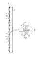
- FIG. 1 is a front view showing a wall panel 1 according to an embodiment of the present invention.
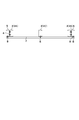
- FIG. 2 is a side view of the wall panel 1.
- 3 is a cross-sectional view of the wall panel 1 taken along line AA of FIG.
- FIG. 4 is a perspective view of the wall panel 1.
- FIG. 5 is an enlarged perspective view showing a part of the wall panel 1.
- the wall panel 1 is used as a load-bearing wall in a framed wall construction building. For example, after the wall panel 1 is installed on a foundation, the lower end portion of the wall panel 1 is connected to an anchor bolt, while the upper end portion of the wall panel 1 is connected to a building beam or a floor panel. Alternatively, the upper and lower ends of the wall panel 1 are connected to the upper and lower beams and the floor panel.
- the wall panel 1 is composed of a combination of a frame member 2 and a folded plate 3.
- the folded plate 3 is a surface material made of a thin steel plate, and as shown in FIG. 2, is a surface material in which a plurality of peak portions 6 and a plurality of valley portions 7 are alternately formed from one side to the other.
- the frame member 2 is made of a thin lightweight steel (grooved steel), and as shown in FIG. 1, a pair of vertical frame members (first frame members) arranged in the extending direction of the valley portion 7 of the folded plate 3. ) 2A and a pair of horizontal frame members (second frame members) 2B arranged along the direction orthogonal to the extending direction of the valley 7 of the folded plate 3 form, for example, a rectangular square frame Yes. Further, a frame member 2C is provided between the vertical frame members 2A. Further, the folded plate 3 is joined to one surface of a quadrilateral frame constituted by the frame member 2A and the frame member 2B. As the frame wall construction method, for example, a relatively small building of about 2 to 4 floors is suitable. In addition to the wall panel 1, pillars, beams, floor panels, roofs, exterior materials, interiors It is composed of materials.
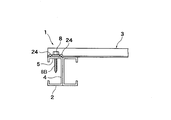
- the frame member 2 of the wall panel 1 includes a web 4 and a pair of flanges 5 that are continuous with both ends of the web 4, and has a substantially C-shaped cross section.
- the vertical frame material 2A provided in a both-ends edge consists of two channel steels mutually joined by the webs 4 mutually.
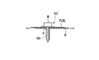
- the screw 8 is a tapping screw or the like, and the screw 8 penetrating the valley portion 7 of the folded plate 3 from the opposite side of the frame member 2 is screwed into the frame member 2, whereby the folded plate 3 is attached to the frame member 2.
- the trough 7 is fixed.
- ⁇ 1 is a coefficient representing a condition for preventing the head portion 8A of the screw 8 from coming out of the screw hole 9 generated in the folded plate 3 due to the support pressure of the shaft portion 8B.
- ⁇ 1 is desirably 7.0 or more. According to such a configuration, even if the screw 8 is repeatedly subjected to a load and the periphery of the shaft portion 8B of the folded plate 3 is deformed by supporting pressure, the screw hole 9 of the screw 8 becomes large. The head 8 ⁇ / b> A is caught on the folded plate 3. Thereby, it can prevent that the screw 8 falls off from the folded plate 3, and can ensure a deformation
- ⁇ 2 is a coefficient representing a condition for preventing the growth of the screw hole 9 from being hindered by local buckling generated in the folded plate 3 by the shaft portion 8B of the screw 8.
- ⁇ 2 is desirably 13 or more. According to such a configuration, a long hole starting from the screw hole 9 is formed in the folded plate 3 by the support pressure of the shaft portion 8B of the screw 8, so that the support pressure caused by wrinkles around the shaft portion 8B is formed. Compared with deformation, higher deformation performance can be ensured.
- the above-described conditions of the screw joint portion 8C which is a joint portion between the frame member 2 and the folded plate 3 and the screw 8 in the wall panel 1, are set.
- the following formula (3) is used. .
- R as R as3-1 ⁇ min ( ⁇ 3 ⁇ R as2 , ⁇ 4 ⁇ R as3 -2 , ⁇ 5 ⁇ R as4 ) (3)
- R as2 is the pull-out resistance (kN) of the screw 8 shown in FIG. 6A and is calculated by the following equation (4).
- R as3-1 is the bearing strength (kN) around the screw of the folded plate 3 shown in FIG. 6B, and is calculated by the following equation (5).
- R as3-2 is the bearing strength (kN) around the screw of the frame member 2 shown in FIG. 6C, and is calculated by the following equation (6).
- R as4 is the axial shear strength (kN) of the screw 8 shown in FIG. 6D and is calculated by the following equation (7).
- t 1 is the design plate thickness (mm) of the folded plate 3
- t 2 is the design plate thickness (mm) of the frame member 2
- F u1 is
- F u2 is the tensile strength (N / mm 2 ) of the frame member 2
- d 1 is the shaft diameter of the shaft portion 8 B of the screw 8.
- Ad is the axial cross-sectional area (mm 2 ) of the screw 8
- D is the head diameter (mm) of the screw 8.
- the pull-out resistance R as2 (kN) of the screw 8 can be obtained by the following equation (4).
- R as2 Cs ⁇ Ce ⁇ d 1 ⁇ t 2 ⁇ F u2 (4)
- Cs 1.3-0.3 ⁇ (d 1/ 5)
- Ce 0.28 ⁇ 3.95 ⁇ ⁇ 0.5 ⁇ (t 2 / d 1 ) 0.5
- ⁇ is an influence coefficient and is calculated by the following equation.
- ⁇ 3.1-5.6 (t 1 / t 2 ) +3.5 (t 1 / t 2 ) 2
- Cs is a coefficient considering the screw diameter.
- Ce is a coefficient that takes into consideration the screw diameter and the frame material plate thickness.
- the bearing strength R as3-1 (kN) around the screw of the folded plate can be obtained by the following equation (5).
- R as3-1 Cs ⁇ Ce ⁇ d 1 ⁇ t 1 ⁇ F u1 (5)
- Ce 1 is a coefficient considering the screw diameter and the folded plate thickness.
- Ce 2 is a constant based on the experimental results.
- the screw bearing strength R as3-2 (kN) of the frame member 2 can be obtained by the following equation (6).
- R as3-2 Cs ⁇ Ce ⁇ d 1 ⁇ t 2 ⁇ F u2 (6)
- Ce 1 is a coefficient considering the screw diameter and the frame material plate thickness.
- Ce 2 is a constant based on the experimental results.
- the axial shear strength R as4 (kN) of the screw 8 can be obtained by the following equation (7).
- R as4 fs ⁇ A d ⁇ 120 ⁇ A d (7)
- fs is the reference strength (N / mm 2 ) of the drill screw.
- the fracture mode at this joint portion is the bearing resistance strength R as3-1 of the folded plate 3 around the screw. Determined by.
- the folded plate 3 in a portion penetrated by the screw 8 is deformed by pressure, so that the screw 8 is pulled out (screwing out resistance R of the screw 8). as2 ), deformation around the screw of the frame member 2 (bearing resistance strength Rs3-2 around the screw of the frame member 2), fracture of the shaft of the screw 8 (shaft shear strength R as4 of the screw 8), etc. do not occur.
- ⁇ 3 to ⁇ 5 do not need to be 1.0 because they may be expressed after other modes are expressed.
- ⁇ 4 to ⁇ 5 have no upper limit, and the lower limit is preferably 0.5 or more.
- ⁇ 3 is preferably in the range of 0.7 to 4.0 because if it is too small, the screw is likely to come out, and if it is too large, the screw may not tilt.
- the shear strength Q U in the entire wall panel 1 is set so as to satisfy the following equation (8).
- Q b in the formula (8) is a shear strength (kN) based on the allowable shear strength R as of the joint portion shown in the following formula (9), and Q y is the shear of the folded plate 3 shown in the formula (10).
- Equation (9) R as is the long-term allowable shear strength of the screw joint, and the maximum strength is about three times that. However, since it is difficult for all the screws 8 to bear the load equally, ⁇ 9 is set to 3.0 to 2.0. As shown in FIG. 4, h is the width (mm) of the wall panel 1, and p is the screw pitch (mm) of the screw 8.
- h is the width (mm) of the wall panel 1 shown in FIG. 4
- t 1 is the thickness (mm) of the folded plate 3 shown in FIG. 5
- F 1 is the F of the folded plate 3. Value (N / mm 2 ).
- I x is a moment of inertia of the cross section per unit length with respect to the neutral axis in the direction orthogonal to the direction of the folding line of the folded plate 3, and is calculated by the equation (11a).
- t 1 is the thickness (mm) of the folded plate 3
- ⁇ is the ratio (L / L1) of the actual dimension (projected length) L of the peak part to the length dimension L1 when the peak part in the direction orthogonal to the folding line direction shown in FIG. This is the rate of decrease in the length of the crests of the folded plate 3.
- I y is a secondary moment of the cross section per unit length with respect to the neutral axis in the direction parallel to the folding line direction of the folded plate 3, and is calculated by the equation (11b).
- the overall buckling strength of the folded plate 3 determined by such an equation (11) is a failure mode in which the entire folded plate 3 buckles across a plurality of peaks 6 and valleys 7. It is the strength when it occurs.
- the big factor which determines the whole buckling strength is the height d of the peak part of the peak part 6, and the whole buckling strength can be ensured by setting the height d of this peak part to a predetermined value or more.
- the local buckling strength of the valley portion 7 of the folded plate 3 determined by such an expression (12) is the strength when a fracture mode in which each valley portion 7 buckles occurs. .
- a major factor that determines the local buckling strength is the width-thickness ratio ⁇ of the valley portion 7. That is, the local buckling strength can be ensured by setting the valley width a of the valley portion 7 to a predetermined value or less.
- the folded plate 3 is more likely to yield shear.
- the periphery of the screw of the folded plate 3 is deformed under pressure, and the screw 8 is inclined.
- part of the burden load applied to the wall panel 1 is changed to a force for inclining the screw 8.
- the folded plate 3 will hold the burden load, and the shear yield of the folded plate 3 can be prevented. Therefore, brittle shear yield can be prevented, and toughness can be secured by supporting pressure deformation around the screw of the folded plate 3, and the energy absorption performance of the wall panel 1 can be enhanced.
- the shear yield strength determined by the overall buckling of the folded plate 3 is greatly affected by the height of the crest of the folded plate 3, and by setting the crest height to a predetermined value or larger, The shear strength determined by the bearing strength of can be exceeded.
- the valley width dimension of the folded plate 3 is set by suppressing the valley width dimension to a predetermined value or less.
- the shear strength determined by the bearing strength around the screw can be exceeded.
- the joint strength at the joint between the folded plate 3, the frame member 2 and the screw 8 is determined by the bearing strength around the screw of the folded plate 3, and it is folded when an external force is applied.
- the periphery of the screw of the plate 3 is configured to deform under pressure.
- a burden load can be hold
- the structural characteristic coefficient can be set small. Thereby, the number of bearing walls (wall length) can be reduced, and the frame material plate thickness and the strength of the joint hardware can be suppressed, thereby increasing the degree of freedom in economic and architectural planning. That is, by joining the frame member 2 and the folded plate 3 by screwing, the joining structure is simplified, and the labor and cost of manufacturing and construction can be reduced.
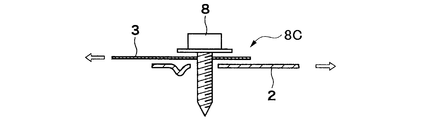
- the ratio of the proof resistance of the screw 9 to the bearing strength of the folded plate 3 (R as2 / R as3-1 ) is the shaft portion of the screw 8 when the folded plate 3 is deformed by bearing pressure.
- 8A is set to the predetermined value which inclines. Thereby, it is possible to prevent the screw 8 from slipping out of the frame member 2 and the screw 8 (particularly, the head 8A) from entering the folded plate 3.
- the ratio of the pullout yield strength of the screw 9 to the bearing strength of the folded plate 3 is 0.7 or more. Thereby, it can prevent that the front-end
- the ratio of the pull-out resistance of the screw 9 to the bearing strength of the folded plate 3 is preferably 1.6 or less. As a result, the screw 8 can be inclined without the screw 8 entering the folded plate 3.
- the ratio of the proof stress of the screw 8 to the bearing strength of the folded plate 3 may be in the range of 0.7 to 4.0.
- FIG. 7A shows the state of the element test of the screw joint portion.
- the element loading test apparatus 14 includes a first force applying jig 16 having a bifurcated mounting arm 15 on one side and a thick plate connecting steel plate on the other side. And a second force applying jig 17 having.
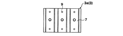
- the both ends of the folded plate piece 3a which is a part of the folded plate 3, are arranged so that the fold line is directed along the bifurcated direction of the arm 15.
- the face material 3 of the trough 7 in the direction of the folding line is fixed by fixing bolts 19 through three washers 18 respectively.
- the web 4 on one end side of the frame member piece 2a which is a part of the frame member 2 is joined to the lower surface of the central portion of the folded plate piece 3a by a screw 8 such as a screw.
- the other end portion of the frame member piece 2 a is superposed on one end portion of the thick plate connecting steel plate 20 and fixed by three bolts 19. Further, the other end of the thick plate connecting steel plate 20 is superposed on the second pressure jig 17 and fixed by a washer and three bolts 19.
- the conditions for the folded plate piece 3a, the frame member piece 2a, and the screw 8 in the test are as follows.
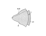
- the cross-sectional shape of the folded plate piece 3a is the shape shown in FIG.
- the frame piece 2a is SGC400 and has a plate thickness of 1.6 mm, the web width dimension is 89 mm, and the flange width is 44.5 mm.
- the screw 8 that joins the folded plate 3 and the frame member 2a in one place is a hexagonal head screw having a nominal diameter of 4.8 mm, and extends over the folded plate 3 and the frame member 2a. And it screwed in and joined to the trough part 7 of the folded plate 3 until the hexagon head contacted.
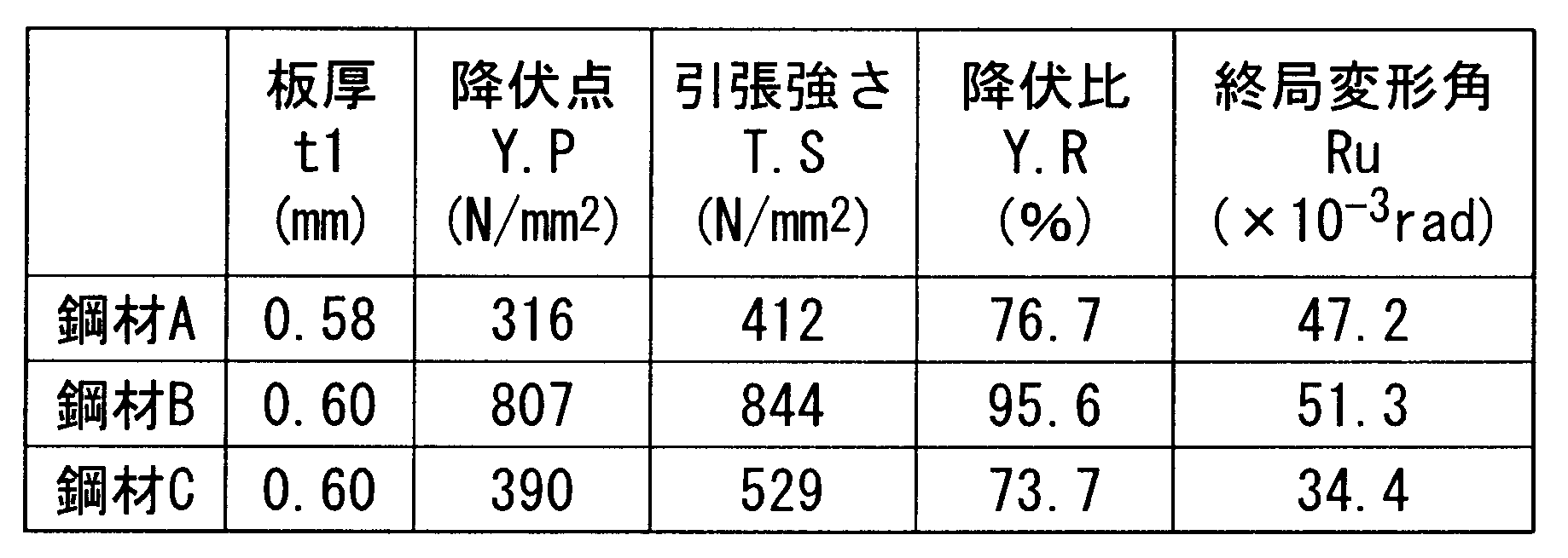
- Each specimen of the folded plate piece 3a is a specimen using four types of steel materials as shown in Table 1.
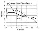
- the load-displacement relationship obtained in this test is shown in FIGS. 9A and 9B.
- the specimen of the steel material B has a ratio of the proof stress of the screw 8 to the bearing strength of the face material 3 of 0.68, and exhibits sufficient deformation performance. As a result, the lower limit of the ratio of the yield strength of the screw 8 to the bearing strength of the face material 3 was set to 0.7.
- the steel material B2 test body has the same surface material 3 and screw diameter as the steel material B test body, but the frame material 2 is overlapped to increase the pull-out resistance of the screw 8, and the screw 8 is less inclined. ing.
- the specimen of the steel material B2 has a deformation ratio of 1.66, which is a ratio of the yield strength of the screw 8 to the bearing strength of the face material 3, which is 1.66.
- the specimen of the steel material A has a ratio of the pull-out resistance of the screw 8 to the bearing capacity of the face material 3 of 1.44, and exhibits sufficient deformation performance. Accordingly, the upper limit of the ratio of the yield strength of the screw 8 to the bearing strength of the face material 3 was set to 1.6. This upper limit is a numerical value when a commercially available screw is used, and the upper limit becomes higher when a large-diameter washer described later is used.
- the specimen D of the steel material D was poor in deformation performance even though the ratio of the yield strength of the screw 8 to the bearing capacity of the face material 3 was higher than that of the steel B specimen. This is because the steel material B is a special low fracture elongation steel and the fracture mechanism is different. When considering only the general steel material D, it is considered that the lower limit of the ratio of the yield strength of the screw 8 to the bearing strength of the face material 3 is increased.
- the face material 3 may be subjected to bearing deformation even when the screw pull-out resistance is smaller than the face material bearing fracture resistance.
- shaft diameter d 1 of the screw 8 is small, the thickness t 1 of the steel sheet by increasing, it is possible to raise the upper limit of the elongation at break.
- d 1 is 4.2 mm or more and t 1 is 0.8 mm or less, so the upper limit of elongation at break is obtained by the following equation (13a).
- (4.2 / 2 + 0.8) / (4.2 / 2 + 0.8 / 2) -1 0.16> El (13a)
- the breaking elongation of the folded plate 3 is less than 16%.
- the shaft portion 8B of the screw 8 is inclined. When it rises along, it is crushed and easily removed.
- the elongation at break of the face material 3 is less than 1%, cracks are likely to occur during folding plate processing, which is not desirable. If the elongation at break of the face material 3 exceeds 16%, it becomes difficult to grind, which is not desirable.
- the breaking elongation of the steel material constituting the folded plate 3 is less than 16%
- the steel plate of the folded plate 3 around the screw hole 9 is plasticized by the shaft portion 8B of the screw 8 and gathers at the tip of the screw 8.
- the steel material of the folded plate 3 is crushed and does not cling to the shaft 8B of the screw 8.
- resistance to the formation of the screw hole 9 elongated in the bearing direction by the shaft portion 8B of the screw 8 can be eliminated, and deformation performance can be ensured while stabilizing the yield strength of the folded plate 3 and the wall panel 1.
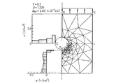
- FIG. 12 shows the stress distribution around the bolt hole
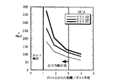
- FIG. 13 shows the stress value depending on the distance from the bolt core.
- the stress change gradient is large. Therefore, by using a washer in this range, it is possible to suppress the screw head from entering the face material.
- FIG. 13 it can be seen that the higher the yield ratio YR of the steel sheet (indicated by ⁇ in FIG. 13), the greater the stress change gradient and the narrower the plasticization region.
- FIGS. 12 shows the yield ratio YR of the steel sheet (indicated by ⁇ in FIG. 13), the greater the stress change gradient and the narrower the plasticization region.
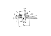
- the ratio of the outer diameter Dw of the washer 33 divided by the shaft diameter d 1 of the shaft portion 8B of the screw 8 (outer diameter Dw / shaft diameter d 1 of the shaft portion 8B of the screw 8).
- the value is 3.0 or more, and it is considered that a sufficient effect can be obtained.
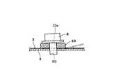
- the shaft diameter d 1 of the shaft 8B Whereas screw 8 of 4.2 mm, using an outer diameter 21mm washer 33 is five times the shaft diameter d 1 of the shaft portion 8B of the screw 8, in FIG. 7A
- the element test of the screw joint part by the apparatus shown and the wall panel loading test by the apparatus of FIG. As a result, when the washer 33 was not inserted, as shown in FIG.
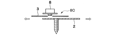
- the head portion 8A of the screw 8 entered under the face material 3 and could not hold the proof stress, and the load bearing wall 1 was severely deteriorated.
- each screw 8 retained the yield strength, and the yield strength could be retained even when the entire bearing wall 1 was greatly deformed.
- the bearing deformation of the face member 3 fixed to the vertical frame member 2A disposed on both ends is larger than that of the horizontal frame member 2B. Therefore, the washer 33 may be inserted only into the screw 8 that fixes the vertical frame member 2 ⁇ / b> A shown in FIG. 1 to the valley portion 7 of the face member 3. Thereby, the overall manufacturing cost can be suppressed while stably securing the bearing deformation around the screw 8 in the face material 3.
- the clearance was smaller, wrinkles of the folded plate 3 occurred from the outer peripheral edge of the washer 33, and local buckling of the valley portion 7 of the folded plate 3 was suppressed.
- wrinkles of the folded plate 3 were generated from the screw holes, and local buckling of the valley portions 7 of the folded plate 3 occurred early.
- FIG. 15A shows the state of the element test of the screw joint.
- the apparatus shown in FIG. 7 replaces the positions of screws and fixing bolts with respect to the apparatus shown in FIG. 7A.
- folded plate piece 3a As the folded plate piece 3a, five types of folded plate element pieces having different shapes and thicknesses were manufactured and tested.
- the cross section of the folding plate piece 3a is a surface material shape, a shape shown in FIG. 16, SGC400 of 0.55 mm (yield point 373N / mm 2, a tensile strength of 505N / mm 2, elongation at break 32%) and did.
- SGC400 As the frame member 2a, SGC400 having a plate thickness of 1.6 mm was used. The web width dimension was 89 mm, and the flange width was 44.5 mm.
- the specimen of the steel material E1 exhibits a sufficient deformation performance because the ratio of the proof stress of the screw 8 to the bearing strength of the folded plate piece 3a which is a face material is 1.32. .
- the steel E2 test body in which two frame material pieces 2a are stacked has a ratio of the proof stress of the screw 8 to the bearing strength of the folded plate piece 3a, which is a face material, as high as 3.16. Was scarce.
- the test body of steel E3 having a washer outer diameter of 21 mm and a clearance between the washer inner diameter and the screw shaft diameter of 0.3 mm exhibited sufficient deformation performance.
- FIG. 18 shows a wall strength test body as a basis for setting an upper limit value of the ratio obtained by subtracting the shaft diameter of the screw shaft from the inner diameter of the washer by the thickness of the washer.
- FIG. 19 shows the load-deformation angle relationship obtained using the load test apparatus of FIG. As shown in FIG. 18, screws with washers were used only on the left and right ends of the outer periphery, and screws without washers were used for the other bearing walls. That is, as described above, the washer 33 is inserted only into the screw 8 that fixes the vertical frame member 2A to the face member 3 having a large bearing deformation.
- the thread pitch P of the screw 8 such as a drilling tapping screw is the plate thickness of the flange 5 in the frame member 2. If it exceeds the dimension, the screw thread will not catch on the frame material at 360 degrees all around. As a result, as shown in FIG. 20, when the screw 8 is inclined, the resistance force cannot be exerted, and the risk of the screw 8 coming out increases.
- the pitch of the screw threads of the screw 8 in the screw joint portion 8C is equal to or less than the plate thickness dimension of the frame member 2, the screw thread in the frame member 2 even when the screw 8 is inclined in the screw joint portion 8C. It can be caught at 360 degrees around the entire circumference, preventing the screw 8 from coming off from the frame member 2, and exhibiting a stable proof stress.
- Drilling tapping screws with nominal diameters of 4.8 mm, 6.0 mm, and 8.0 mm are known, but the thread pitch is 1.6 mm when the nominal diameter is 4.8 mm, and the nominal diameter is The nominal diameter and pitch are not proportional to 6.0 mm and 1.8 mm, and the nominal diameter is 8.0 mm and 1.0 mm. Therefore, it is preferable to use a screw 8 having a smaller thread pitch than the thickness of the flange 5 of the frame member 2.
- a comparative test by a load test for pushing and pulling was performed on a wall panel using a folded plate made of three kinds of steel, for the bearing deformation of the folded plate 3 by a screw at the screw joint.
- Each wall panel 1 was joined to a lower side applying jig 27 via a hole down hardware 26 joined to both sides of the lower side.
- the upper part of the wall panel 1 was joined to a loading beam 29 attached to a loading jig 28 on the upper side, and loaded by pushing and pulling a loading jack 30 joined to the loading beam.
- the shape of the test body and the shape of the folded plate are the same as in FIG. 18, but all the screws in which the folded plate is joined to the frame member are screws without washer.
- the load-deformation angle relationship obtained from loading is shown in FIG.
- the deformation angle in FIG. 23 is the inclination of the wall panel 1 calculated from the two displacement meters 32 in FIG.
- the ultimate deformation angle Ru of the wall panel 1 using the steel materials A and B was 1.3 times or more larger than the ultimate deformation angle Ru of the wall panel 1 using the steel material C.
- FIG. 24A when a force is applied in the direction of shifting in the frame surface between the frame member 2 and the face member 3 when a supporting pressure is applied to the face member 3 of the low YR from the shaft portion 8B of the screw 8.
- the state of the action of the force and the state of deformation are shown.
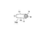
- the crack propagation direction is a direction spreading around the screw 8.
- the breaking line 12 is entirely spread in the direction opposite to the crack propagation direction, and the long hole 10 is formed. Further, the face material 3 is plastically deformed, and wrinkles 13 are generated in the crack propagation direction.
- the crack propagation direction goes straight as shown in FIG. 24C.
- the frame material 2 and the face material 3 are deviated from this state, as shown in FIG. 24D, the fracture line 11 spreads straightly in the direction opposite to the crack propagation direction.
- the long hole 10 to be formed is smaller when the high YR face material 3 is used than when the low YR face material 3 is used. That is, from the test results of the face material of the high yield ratio steel (high YR steel) as described above and the face material of the low yield ratio steel (low YR steel), as shown in FIG. 24C and FIG.
- the higher steel folded plate may suppress the spread of the plasticized region of the steel material around the screw hole and ensure stable bearing deformation.
- the screw shaft portion rotates around the screw shaft.
- the yield ratio YR of the steel material of the folded plate 3 for example, by setting the yield ratio YR to 77% or more (the yield ratio of the steel material is at least 77%), the screw shaft portion rotates around the screw shaft.
- the face material is plasticized, the plasticized region around the screw hole can be suppressed. Thereby, even if the screw head does not come out and the periphery of the screw hole becomes plastic, a narrow screw hole can be formed, and the yield strength can be stabilized.
- the width B of the yield region may be set to be equal to or less than the diameter of the screw, so that the following expressions (14c) to (14g) must be satisfied.
- d 1> B d 1/ 2 ⁇ ⁇ ⁇ F u1 / F 1 ... (14d) ⁇ / 2 ⁇ F 1 / F u1 (14e)
- ⁇ 90 °
- ⁇ / 4 ⁇ F 1 / F u1 14f
- the yield ratio (F 1 / F u1 ) of the folded plate is 79% or more.
- the wall panel was deformable. This is because it is assumed that the face material in the portion in contact with the screw 8 bears stress uniformly, and that the angle ⁇ in the range where the face material can bear the proof stress is assumed to be 90 °, etc. It is thought to be due to. Therefore, it is understood that the yield ratio should be 77% or more based on the experimental values.
- the plasticization region is widened and the hole width is widened, so that the screw (particularly, the head portion of the screw) can easily enter the face material. Therefore, it can be seen that the yield ratio of the folded plate 3 should be 77% or more. Moreover, although there is no upper limit in particular, since it is confirmed up to 96% by the experimental value, about 96% is desirable.
- the folded plate 3 for example, the yield ratio is 77% to 96%) 3 as a face material having a high yield ratio is used, the steel plate in the valley portion of the folded plate 3 supported by the screw 8 in the screw joint 8C is obtained.
- the plasticized region becomes about the screw hole diameter. That is, since the hole width of the screw hole does not widen, the proof stress can be stabilized even when deformed, and the wall panel can be stable even if deformed.
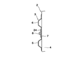
- the extending direction of the valley portion 7 (folded plate 3 around the screw 8 is centered on the screw hole of the folded plate 3 through which the shaft portion 8B of the screw 8 is inserted.
- Ribs 24 extending in a direction perpendicular to the extending direction of the valley portion 7 are provided on both sides of the screw joint portion 8 ⁇ / b> C along the crease line direction).
- the face material can be plasticized in a predetermined direction in the bearing wall.
- the rib 24 may be formed at the same time when the folded plate 3 is press-molded. After the folded plate 3 is rolled, only the rib 24 portion is formed by pressing. May be.
- the processing length of the rib 24 may be greater than the diameter of the screw hole and close to the vicinity of the peak portion 6.
- the ribs 24 are provided on one side or both sides where wrinkles are expected to occur during plasticization.
- valleys are formed on both sides of the folded plate 3 around the screw hole 31 through which the shaft portion 8B of the screw 8 is inserted and along the direction perpendicular to the extending direction of the valley portion 7.
- a thin plate portion (thin wall portion) 25 having a plate thickness dimension smaller than the plate thickness of the portion 7 is formed. Thereby, the intensity
- the means for forming the thin plate portion 25 so as to connect to the screw hole 31 may be formed simultaneously with the press forming of the folded plate 3.
- the processing method it is considered that press processing or cutting processing is suitable.
- the processing width of the thin plate portion 25 is about the diameter of the screw hole 31, and the length may be formed up to the vicinity of the peak portion 6.
- the thin plate portion 25 may be formed by providing a concave portion by cutting or the like on the surface side of the valley portion 7. Moreover, you may make it form by providing a recessed part in the back surface side of the trough part 7 by cutting. Furthermore, you may make it form by providing a recessed part in the front and back both surfaces of the trough part 7 by cutting.
- the thin plate portion 25 is a concave portion formed on the surface side of the valley portion 7, the concave portion can be used for positioning when the screw 8 is screwed in when the screw is screwed.
- the portion to be plastically deformed by supporting the shaft 8B of the screw 8 may be used as the thin plate portion 25 to reduce the strength.
- the material strength may be reduced by heat treatment or chemical treatment without changing the plate thickness. Alternatively, a low strength portion may be formed.
- the position of the screw hole 31 is preferably provided in the thin plate portion 25 as shown in FIGS. 27C and 27D.
- the above-mentioned steel house is usually defined as a steel panel structure building that is constructed by combining a frame material made of a thin lightweight steel with a thickness of 0.4 mm or more and less than 2.3 mm and a structural face material. .
- high yield point (high YP) steel is used as the folded plate 3 or the frame member 2
- the weight can be reduced.
- high YP high yield point
- high YR high yield ratio
- the folded plate 3 is made of a steel material having a low elongation at break (low El), a long and narrow screw hole is formed without causing a sudden decrease in the proof stress, so that the deformation performance of the wall panel 1 can be easily secured.
- the present invention can be applied to a wall panel for building a thin plate lightweight section steel that constitutes a building such as a thin plate lightweight section steel building.
Landscapes
- Engineering & Computer Science (AREA)
- Architecture (AREA)
- Civil Engineering (AREA)
- Structural Engineering (AREA)
- Load-Bearing And Curtain Walls (AREA)
- Panels For Use In Building Construction (AREA)
Abstract
Description
本願は、2009年12月22日に、日本に出願された特願2009-291205号に基づき優先権を主張し、その内容をここに援用する。
また、特許文献4に記載の壁パネルでは、折板の機械的特性(降伏比あるいは破断伸び等)について明確に示唆されていない。これにより、折板におけるねじ接合部の支圧変形を安定的に確保できず、最大耐力発揮後の耐力低下が大きい場合が生じる可能性もあるという問題がある。
すなわち、
(1)本発明の壁パネルは、互いに間隔をおいて対向配置された一対の枠材と;これら枠材に固定され、の一方から他方に向かって山部及び谷部が交互に形成された薄鋼板の折板である面材と;この面材の谷部を各枠材に対して固定するねじと;を備え、各枠材に対して構面内せん断力が作用した場合に、面材の、ねじの周囲部分が支圧変形して抵抗する耐力壁用の壁パネルであって、面材の支圧耐力に対するねじの抜け出し耐力の比が、面材の支圧変形時に、ねじの軸部が傾斜する所定値に設定されていることを特徴とする。
(5)上記(4)に記載の本発明の壁パネルでは、所定値が4.0以下であってもよい。
(7)上記(4)に記載の本発明の壁パネルでは、ワッシャの孔とねじの軸部との間に隙間が形成されていてもよい。
(8)上記(4)に記載の本発明の壁パネルでは、ワッシャの内径寸法からねじの軸部の軸径寸法を差し引いた差をワッシャの厚さ寸法で除算した比が、0.1~0.6であってもよい。
上記(5)に記載の本発明の壁パネルによれば、ワッシャを用いることにより、面材の支圧耐力に対するねじの抜け出し耐力の比の上限を緩和することができる。すなわち、上記所定値が4.0以下で、ねじが耐力を保持することができ、ねじが面材の下に潜り込むことなく、ねじを傾斜させることができる。
また、第1の枠材と第2の枠材とにより四角枠が形成される場合、第2の枠材に固定された面材の支圧変形に比べて、第1の枠材に固定された面材の支圧変形の方が大きい。そこで、上記(6)に記載の本発明の壁パネルによれば、第1の枠材に対して面材を固定するねじにのみワッシャが挿入されているため、ねじ(特に、ねじの頭部)が面材の下に潜り込むのを抑制しながら、組立工程及び部品点数を削減することができる。すなわち、面材におけるねじ周囲の支圧変形を安定的に確保しつつ、全体的な生産コストを抑えることができる。
上記(8)に記載の本発明の壁パネルによれば、ワッシャの内径寸法、ねじの軸部の軸径寸法及びワッシャの厚さ寸法を規定することにより、適正な傾斜角度でねじを傾斜させることができる。
そこで、上記(9)に記載の本発明の壁パネルによれば、面材の破断伸びが1%以上かつ16%未満である。このように、破断伸びが小さい面材を用いることにより、ねじによって支圧されるねじ周りの面材の塑性化部が、粉砕されて排除され易くなる。これにより、ねじ周りに集まった塑性化された面材が、ねじに抵抗することがないので、面材を安定して塑性変形させることができる。さらには、安定した耐力と変形性能とを発揮させることができる。
枠材2は、薄板軽量形鋼(溝形鋼)からなり、図1に示すように、折板3の谷部7の延在方向に配置された一対の縦枠材(第1の枠材)2Aと、折板3の谷部7の延在方向に直交する方向に沿って配置された一対の横枠材(第2の枠材)2Bとにより、例えば長方形の四角枠を形成している。さらに、縦枠材2Aの間には、枠材2Cが設けられている。また、折板3は、枠材2A及び枠材2Bにより構成された四周枠組みの一方の面に接合されている。
枠組壁工法建築物としては、例えば、2階建て~4階建て程度の比較的小規模な建物が好適であり、壁パネル1の他に、柱、梁、床パネル、屋根、外装材、内装材等を有して構成されている。
ねじ8は、タッピングビスなどであり、枠材2の反対側から折板3の谷部7を貫通したねじ8が、枠材2に螺合することで、枠材2に対して折板3の谷部7を固定する。
(D-d1)>α1・t1 …(1)
d1<α2・t1 …(2)
Ras=Ras3-1<min(α3・Ras2,α4・Ras3-2,α5・Ras4) …(3)
Ras2=Cs×Ce×d1×t2×Fu2 …(4)
Cs=1.3-0.3×(d1/5)
Ce=0.28×3.95×ξ0.5×(t2/d1)0.5
ここで、ξは影響係数であり、次式で算出される。
ξ=3.1-5.6(t1/t2)+3.5(t1/t2)2
Csは、ねじ径を考慮する係数である。また、Ceは、ねじ径と枠材板厚を考慮する係数である。
Ras3-1=Cs×Ce×d1×t1×Fu1 …(5)
Ce=min(Ce1,Ce2)
Ce1=0.28×{0.471+9.42×t2/d1}
Ce2=0.959
ここで、Ce1は、ねじ径と折板板厚を考慮する係数である。また、Ce2は、実験結果に基づく定数である。
Ras3-2=Cs×Ce×d1×t2×Fu2 …(6)
Ce=min(Ce1,Ce2)
Ce1=0.28×{1.18+5.26×t1/d1}
Ce2=0.677
ここで、Ce1は、ねじ径と枠材板厚を考慮する係数である。また、Ce2は、実験結果に基づく定数である。
Ras4=fs×Ad≒120×Ad …(7)
ここで、fsはドリルねじの基準強度(N/mm2)である。
Ix=t1 3(δ2十1)/(6η) …(11a)
Iy=t1 3/{12(1-μ2)} …(11b)
(i)折板3におけるねじ接合部付近の支圧変形時に、ねじ8のねじ先が抜けることにより接合部が破壊される場合。
(ii)ねじ接合部付近の支圧変形時に、折板3(面材)が支圧変形して、接合部が破壊される場合。
(iii)ねじ接合部付近の支圧変形時に、枠材2が支圧変形して、接合部が破壊される場合。
(iv)ねじ接合部付近の支圧変形時に、ねじ8の軸部8Bが破断して、接合部が破壊される場合。
ただし、後述のワッシャを用いた場合には、折板3の支圧耐力に対するねじ8の抜け出し耐力の比は、0.7~4.0の範囲であればよい。
(i)折板片3aの断面形状は図8に示す形状とした。
(ii)枠材片2aは、SGC400でかつ板厚が1.6mmのものを使用し、ウェブ幅寸法が89mmで、フランジ幅が44.5mmとした。
(iii)折板3と枠材片2aとを1箇所で接合するねじ8は、六角頭ねじでかつ呼び径が4.8mmのものを使用し、折板3と枠材片2aとに渡って、折板3の谷部7に六角頭が接触するまでねじ込んで接合した。

(d1/2+t1)/(d1/2+t1/2)-1>El …(13)
(4.2/2+0.8)/(4.2/2+0.8/2)-1=0.16>El …(13a)
図14A及び図14Bに示すように、ワッシャ33の外径Dwをねじ8の軸部8Bの軸径d1で除算した比(外径Dw/ねじ8の軸部8Bの軸径d1)の値は3.0以上となり、十分な効果が得られると考えられる。実際に、軸部8Bの軸径d1が4.2mmのねじ8に対し、ねじ8の軸部8Bの軸径d1の5倍である外径21mmのワッシャ33を用いて、図7Aに示す装置によるねじ接合部の要素試験と、後述する図22の装置による壁パネル載荷試験とを行った。その結果、ワッシャ33を挿入しない場合、図10Aに示すように、ねじ8の頭部8Aが面材3の下に潜り込んで耐力が保持できず、耐力壁1の劣化が激しかった。これに対し、ワッシャ33を挿入した場合には、各々のねじ8が耐力を保持し、耐力壁1全体が大きく変形した時にも耐力を保持することができた。
また、横枠材2Bに比べて、両端側に配置された縦枠材2Aに固定された面材3の支圧変形の方が大きい。そこで、ワッシャ33は、図1に示す縦枠材2Aを面材3の谷部7に固定するねじ8にのみ挿入されていても良い。これにより、面材3におけるねじ8周囲の支圧変形を安定的に確保しつつ、全体的な製造コストを抑えることができる。
また、図14Aに示すように、前記クリアランスが小さいと、面材3が僅かに変形しただけで、ねじ8とワッシャ33が一体化し、ワッシャ33の浮き上がりが抑えられる。これにより、折板3の谷部7の局部座屈の折れ曲がり線が、図14Aの黒点で示すように、ワッシャ33の外縁から発生する。これに対し、図14Bに示すように、クリアランスが大きいと、ねじ8とワッシャ33は、折板3が大きく変形するまで、それぞれ独立して傾き、ワッシャ33の浮き上がりが抑制されない。これにより、折板3の谷部7の局部座屈の折れ曲がり線が、図14Bの黒点で示すように、ねじ8の中心から発生する。つまり、折板3の谷部7の端(斜面の麓)までの距離を座屈長さとすると、クリアランスが大きい場合には、折板3の谷部7の局部座屈が早期に起こりやすくなる。したがって、ワッシャ33の厚さtwに対するクリアランス(ワッシャ33の内径dwとねじ8の軸部8Bの軸径d1との差)、すなわち、ワッシャ33の内径寸法からねじ8の軸部8Bの軸径寸法を差し引いた差をワッシャ33の厚さ寸法で除算した比である(dw-d1)/twの値は、0.1~0.6であることが望ましい。実際に、(dw-d1)/twの値が0.13のワッシャ33(Dw=18mm,dw=5.5mm,tw=2.0mm)と0.65のワッシャ33(Dw=21mm,dw=4.5mm,tw=2.3mm)とを用いて、図15Aに示す装置によるねじ接合部8Cの要素試験と、後述する図22に示す装置による壁パネル載荷試験とを行った。その結果、クリアランスが小さい方は、ワッシャ33の外周縁から折板3のしわが発生し、折板3の谷部7の局部座屈が抑制された。これに対し、クリアランスが大きい方は、ねじ孔から折板3のしわが発生し、折板3の谷部7の局部座屈が早期に発生した。
(i)面材である折板片3aの断面形状は、図16に示す形状とし、0.55mmのSGC400(降伏点373N/mm2、引張強さ505N/mm2、破断伸び32%)とした。
(ii)枠材片2aは、SGC400でかつ板厚が1.6mmのものを使用した。ウェブ幅寸法は89mmとし、フランジ幅は44.5mmとした。
(iii)折板3と枠材片2aとを1箇所で接合するねじ8としては、六角頭ねじでかつ呼び径が4.2mmのものを使用した。そして、このねじ8を、折板3と枠材片2aとに渡って、折板3の谷部7に六角頭が接触するまでねじ込んで接合した。
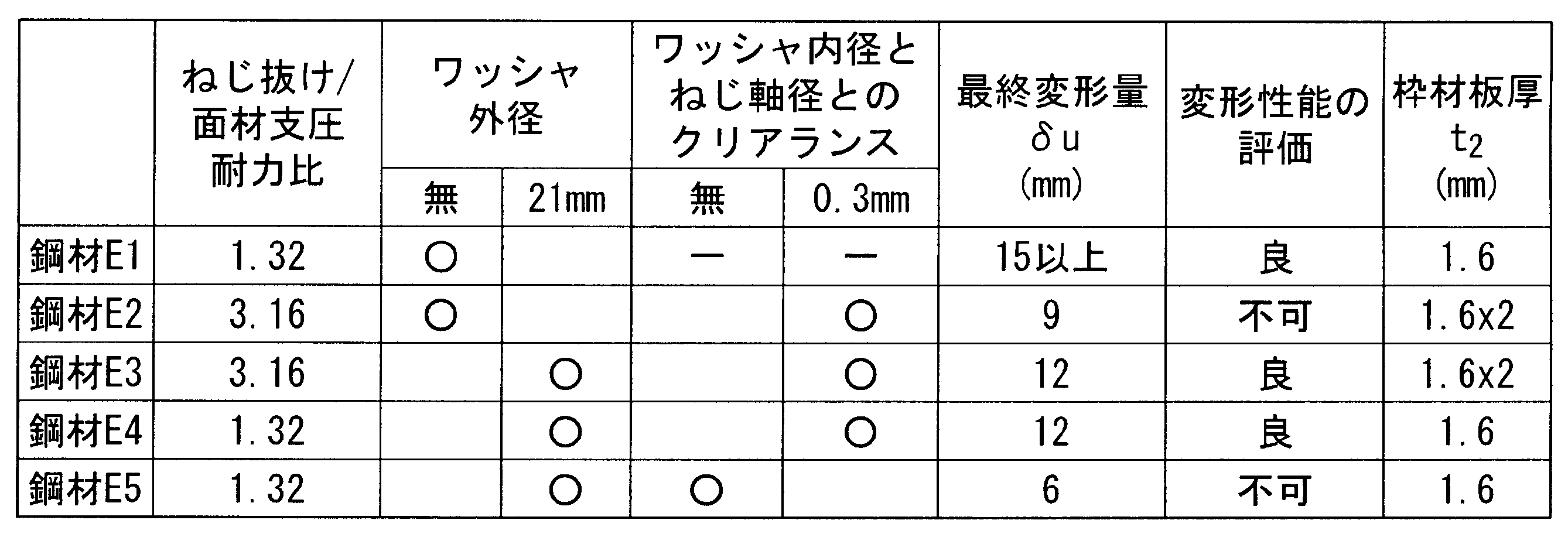
図17Bに示すように、ワッシャ内径とねじ軸径とのクリアランスが無い(ワッシャには小さな先孔しかあけず、ワッシャ自体をねじでねじ切りしてねじと一体化した)鋼材E5の試験体については、クリアランスが0.3mmの鋼材E4の試験体に較べて小さな変形でねじの軸部が破断し、変形性能が乏しかった。この結果より、変形性能を確保するには適度なクリアランスが必要で、実験ではワッシャ厚さに対するクリアランスは0.15(=0.3/2.0)であったことから、ワッシャの内径寸法からねじの軸部の軸径寸法を差し引いた差をワッシャの厚さ寸法で除算した比の下限値を、0.1とした。
一方、高YRの面材3に支圧力が作用した場合、図24Cに示すように、亀裂進展方向は直進する。この状態から枠材2と面材3とがずれると、図24Dに示すように、亀裂進展方向と反対の方向に破断線11が直進的に広がる。このとき、低YRの面材3を用いた場合に比べて、高YRの面材3を用いた方が、形成される長孔10が小さい。
すなわち、前記のような高降伏比鋼(高YR鋼)の面材と、低降伏比鋼(低YR鋼)の面材との試験結果から、図24C及び図24Dに示すように、降伏比の高い鋼材の折板のほうが、ねじ孔周辺の鋼材の塑性化領域の広がりを抑え、安定した支圧変形を確保できる可能性がある。
d1/2・θ・Fu1=B・F1 …(14a)
B=d1/2・θ・Fu1/F1 …(14b)
d1>B …(14c)
d1>B=d1/2・θ・Fu1/F1 …(14d)
θ/2<F1/Fu1 …(14e)
ここで、θ=90゜とすると
π/4<F1/Fu1 …(14f)
0.785<F1/Fu1 …(14g)
2 枠材
2a 枠材片
3 折板(面材)
3a 折板片
4 ウェブ
5 フランジ
6 山部
7 谷部
8 ねじ
8A 頭部
8B ねじ軸部
8C ねじ接合部
8D 先端
9 ねじ孔
10 長孔
11 破断線
12 破断線
13 しわ
14 載荷試験装置
15 アーム
16 第1加力治具
17 第2加力治具
18 座金
19 ボルト
20 厚板連結鋼板
21 塑性化部
22 屈曲部
23 亀裂
24 リブ
25 薄板部分
26 ホールダウン金物
27 下部側の加力治具
28 上部側の加力治具
29 載荷梁
30 加力ジャッキ
31 ねじ孔
32 変位計
33 ワッシャ
33a 孔
Claims (14)
- 互いに間隔をおいて対向配置された一対の枠材と;
これら枠材に固定され、一方から他方に向かって山部及び谷部が交互に形成された薄鋼板の折板である面材と;
この面材の前記谷部を前記各枠材に対して固定するねじと;
を備え、前記各枠材に対して構面内せん断力が作用した場合に、前記面材の、前記ねじの周囲部分が支圧変形して抵抗する耐力壁用の壁パネルであって、
前記面材の支圧耐力に対する前記ねじの抜け出し耐力の比が、前記面材の支圧変形時に、前記ねじの軸部が傾斜する所定値に設定されている
ことを特徴とする壁パネル。 - 前記所定値が0.7以上であることを特徴とする請求項1に記載の壁パネル。
- 前記所定値が1.6以下であることを特徴とする請求項1または2に記載の壁パネル。
- 前記ねじが挿入されるワッシャをさらに備え、
このワッシャの外径寸法を前記ねじの前記軸部の軸径寸法で除算した比が、3.0以上であることを特徴とする請求項1または2に記載の壁パネル。 - 前記所定値が4.0以下であることを特徴とする請求項4に記載の壁パネル。
- 前記枠材が、前記谷部の延在方向に配置された第1の枠材と、前記谷部の延在方向に直交する方向に配置された第2の枠材とを備え、
前記第1の枠材と前記第2の枠材とにより四角枠を形成し、
前記面材の前記谷部に前記第1の枠材を固定する前記ねじにのみ前記ワッシャが挿入されていることを特徴とする請求項4に記載の壁パネル。 - 前記ワッシャの孔と前記ねじの前記軸部との間に隙間が形成されていることを特徴とする請求項4に記載の壁パネル。
- 前記ワッシャの内径寸法から前記ねじの前記軸部の軸径寸法を差し引いた差を前記ワッシャの厚さ寸法で除算した比が、0.1~0.6であることを特徴とする請求項4に記載の壁パネル。
- 前記面材の破断伸びが1%以上かつ16%未満であることを特徴とする請求項1に記載の壁パネル。
- 前記ねじのねじ山のピッチが、前記各枠材の板厚寸法以下であることを特徴とする請求項1に記載の壁パネル。
- 前記面材の降伏比が77%~96%であることを特徴とする請求項1に記載の壁パネル。
- 前記面材の、前記ねじの前記軸部が挿通されるねじ孔を中心として、前記谷部の延在方向に沿った少なくとも片側に、前記谷部の前記延在方向に直交するリブがさらに設けられていることを特徴とする請求項1に記載の壁パネル。
- 前記面材の、前記ねじの前記軸部が挿通されるねじ孔を中心として、前記谷部の延在方向に直交する方向に沿った両側に、部分的に板厚が薄い薄肉部が形成されていることを特徴とする請求項1に記載の壁パネル。
- 前記面材の、前記ねじの前記軸部が挿通されるねじ孔を中心として、前記谷部の延在方向に直交する方向に沿った両側に、部分的に機械的強度が周囲よりも低い低強度部が形成されていることを特徴とする請求項1に記載の壁パネル。
Priority Applications (2)
| Application Number | Priority Date | Filing Date | Title |
|---|---|---|---|
| MYPI2012700358A MY184597A (en) | 2009-12-22 | 2010-06-22 | Wall panel |
| CN201080058126.4A CN102959161B (zh) | 2009-12-22 | 2010-06-22 | 壁板 |
Applications Claiming Priority (2)
| Application Number | Priority Date | Filing Date | Title |
|---|---|---|---|
| JP2009-291205 | 2009-12-22 | ||
| JP2009291205A JP4580458B2 (ja) | 2008-12-22 | 2009-12-22 | 薄板軽量形鋼造用の壁パネル |
Publications (1)
| Publication Number | Publication Date |
|---|---|
| WO2011077604A1 true WO2011077604A1 (ja) | 2011-06-30 |
Family
ID=42701277
Family Applications (1)
| Application Number | Title | Priority Date | Filing Date |
|---|---|---|---|
| PCT/JP2010/004150 Ceased WO2011077604A1 (ja) | 2009-12-22 | 2010-06-22 | 壁パネル |
Country Status (5)
| Country | Link |
|---|---|
| JP (1) | JP4580458B2 (ja) |
| CN (1) | CN102959161B (ja) |
| MY (1) | MY184597A (ja) |
| TW (1) | TWI465626B (ja) |
| WO (1) | WO2011077604A1 (ja) |
Families Citing this family (2)
| Publication number | Priority date | Publication date | Assignee | Title |
|---|---|---|---|---|
| JP7063564B2 (ja) * | 2017-09-28 | 2022-05-09 | 大和ハウス工業株式会社 | 床パネル構成体、乾式床構造および乾式床構造作製方法 |
| KR102205045B1 (ko) * | 2020-09-14 | 2021-01-19 | 김완수 | 홀 성형 장치 |
Citations (1)
| Publication number | Priority date | Publication date | Assignee | Title |
|---|---|---|---|---|
| JP2009209582A (ja) * | 2008-03-04 | 2009-09-17 | Nippon Steel Corp | パネル、建築物および薄板軽量形鋼造建築物 |
Family Cites Families (6)
| Publication number | Priority date | Publication date | Assignee | Title |
|---|---|---|---|---|
| US4176503A (en) * | 1977-08-29 | 1979-12-04 | H. H. Robertson Company | Controlled release wall structure |
| JPH0249449U (ja) * | 1988-09-30 | 1990-04-05 | ||
| JPH09228520A (ja) * | 1996-02-28 | 1997-09-02 | Nippon Kokan Light Steel Kk | 波板製壁材の耐震壁構造 |
| US7282642B2 (en) * | 2002-06-06 | 2007-10-16 | Leviton Manufacturing Co., Inc. | Shaped wall plate for wiring device |
| JP5098052B2 (ja) * | 2006-04-11 | 2012-12-12 | 新日鐵住金株式会社 | 壁パネル |
| CN101245616A (zh) * | 2008-03-13 | 2008-08-20 | 同济大学 | 高层竖向剪切耗能钢板墙结构体系 |
-
2009
- 2009-12-22 JP JP2009291205A patent/JP4580458B2/ja active Active
-
2010
- 2010-06-22 CN CN201080058126.4A patent/CN102959161B/zh active Active
- 2010-06-22 WO PCT/JP2010/004150 patent/WO2011077604A1/ja not_active Ceased
- 2010-06-22 TW TW099120373A patent/TWI465626B/zh active
- 2010-06-22 MY MYPI2012700358A patent/MY184597A/en unknown
Patent Citations (1)
| Publication number | Priority date | Publication date | Assignee | Title |
|---|---|---|---|---|
| JP2009209582A (ja) * | 2008-03-04 | 2009-09-17 | Nippon Steel Corp | パネル、建築物および薄板軽量形鋼造建築物 |
Also Published As
| Publication number | Publication date |
|---|---|
| TWI465626B (zh) | 2014-12-21 |
| JP2010168892A (ja) | 2010-08-05 |
| CN102959161A (zh) | 2013-03-06 |
| JP4580458B2 (ja) | 2010-11-10 |
| CN102959161B (zh) | 2014-12-17 |
| TW201122190A (en) | 2011-07-01 |
| MY184597A (en) | 2021-04-06 |
Similar Documents
| Publication | Publication Date | Title |
|---|---|---|
| Niari et al. | Seismic behavior of steel sheathed cold-formed steel shear wall: experimental investigation and numerical modeling | |
| Qin et al. | Experimental seismic behavior of through-diaphragm connections to concrete-filled rectangular steel tubular columns | |
| Wang et al. | Seismic behavior of blind bolted CFST frames with semi-rigid connections | |
| Shi et al. | Innovative inner sleeve composite bolted connections for modular steel constructions: Experimental and numerical studies | |
| Wang et al. | Cyclic testing of steel beam blind bolted to CFST column composite frames with SBTD concrete slabs | |
| Tsavdaridis et al. | Experimental behaviour of non-seismical RWS connections with perforated beams under cyclic actions | |
| Selvaraj et al. | Sheathing bracing requirements for cold-formed steel wall panels: experimental investigation | |
| Wang et al. | Cyclic behavior of panel zone in beam-column subassemblies subjected to bidirectional loading | |
| JP2011001792A (ja) | ラーメン骨組の柱梁接合部構造および圧延h形鋼 | |
| CN109113263B (zh) | 一种加固钢结构梁或柱的施工方法 | |
| Essa et al. | Behavior of roof deck diaphragms under quasistatic cyclic loading | |
| Sun et al. | Seismic behaviour of I-beams bolted CFST column connection using extended TSOBs | |
| CN206625402U (zh) | 一种侧边开缝交叉加劲压型钢板剪力墙 | |
| Aktepe et al. | Experimental investigation on lateral behavior of novel hybrid cold-formed steel walls with composite sheathing | |
| CN106436969A (zh) | 一种侧边开缝交叉加劲压型钢板剪力墙 | |
| WO2011077604A1 (ja) | 壁パネル | |
| JP2010090650A (ja) | 折板パネル構造および建築構造物 | |
| JP4411444B2 (ja) | 構造物へのせん断パネル型ダンパー取付け構造 | |
| JP4987758B2 (ja) | パネル、建築物および薄板軽量形鋼造建築物 | |
| JP7351271B2 (ja) | 鉄骨梁、柱梁接合構造およびこれを有する構造物 | |
| JP2009035949A5 (ja) | ||
| CN201722788U (zh) | 一种带钢销钉的埋入式钢柱脚 | |
| JP6128058B2 (ja) | 梁端部の接合構造 | |
| JP7335540B1 (ja) | 接合構造 | |
| CN217711381U (zh) | 一种新型装配式钢管混凝土组合柱防屈曲套箍结构 |
Legal Events
| Date | Code | Title | Description |
|---|---|---|---|
| WWE | Wipo information: entry into national phase |
Ref document number: 201080058126.4 Country of ref document: CN |
|
| 121 | Ep: the epo has been informed by wipo that ep was designated in this application |
Ref document number: 10838845 Country of ref document: EP Kind code of ref document: A1 |
|
| NENP | Non-entry into the national phase |
Ref country code: DE |
|
| WWE | Wipo information: entry into national phase |
Ref document number: 1201003002 Country of ref document: TH |
|
| 122 | Ep: pct application non-entry in european phase |
Ref document number: 10838845 Country of ref document: EP Kind code of ref document: A1 |