WO2011070645A1 - 連結車両のスウェイ状態抑制のための挙動制御装置 - Google Patents
連結車両のスウェイ状態抑制のための挙動制御装置 Download PDFInfo
- Publication number
- WO2011070645A1 WO2011070645A1 PCT/JP2009/070501 JP2009070501W WO2011070645A1 WO 2011070645 A1 WO2011070645 A1 WO 2011070645A1 JP 2009070501 W JP2009070501 W JP 2009070501W WO 2011070645 A1 WO2011070645 A1 WO 2011070645A1
- Authority
- WO
- WIPO (PCT)
- Prior art keywords
- sway
- vibration
- tractor
- yaw rate
- lateral acceleration
- Prior art date
- Legal status (The legal status is an assumption and is not a legal conclusion. Google has not performed a legal analysis and makes no representation as to the accuracy of the status listed.)
- Ceased
Links
Images


Classifications
-
- B—PERFORMING OPERATIONS; TRANSPORTING
- B60—VEHICLES IN GENERAL
- B60T—VEHICLE BRAKE CONTROL SYSTEMS OR PARTS THEREOF; BRAKE CONTROL SYSTEMS OR PARTS THEREOF, IN GENERAL; ARRANGEMENT OF BRAKING ELEMENTS ON VEHICLES IN GENERAL; PORTABLE DEVICES FOR PREVENTING UNWANTED MOVEMENT OF VEHICLES; VEHICLE MODIFICATIONS TO FACILITATE COOLING OF BRAKES
- B60T7/00—Brake-action initiating means
- B60T7/12—Brake-action initiating means for automatic initiation; for initiation not subject to will of driver or passenger
- B60T7/20—Brake-action initiating means for automatic initiation; for initiation not subject to will of driver or passenger specially for trailers, e.g. in case of uncoupling of or overrunning by trailer
-
- B—PERFORMING OPERATIONS; TRANSPORTING
- B60—VEHICLES IN GENERAL
- B60T—VEHICLE BRAKE CONTROL SYSTEMS OR PARTS THEREOF; BRAKE CONTROL SYSTEMS OR PARTS THEREOF, IN GENERAL; ARRANGEMENT OF BRAKING ELEMENTS ON VEHICLES IN GENERAL; PORTABLE DEVICES FOR PREVENTING UNWANTED MOVEMENT OF VEHICLES; VEHICLE MODIFICATIONS TO FACILITATE COOLING OF BRAKES
- B60T8/00—Arrangements for adjusting wheel-braking force to meet varying vehicular or ground-surface conditions, e.g. limiting or varying distribution of braking force
- B60T8/17—Using electrical or electronic regulation means to control braking
- B60T8/1701—Braking or traction control means specially adapted for particular types of vehicles
- B60T8/1708—Braking or traction control means specially adapted for particular types of vehicles for lorries or tractor-trailer combinations
-
- B—PERFORMING OPERATIONS; TRANSPORTING
- B60—VEHICLES IN GENERAL
- B60T—VEHICLE BRAKE CONTROL SYSTEMS OR PARTS THEREOF; BRAKE CONTROL SYSTEMS OR PARTS THEREOF, IN GENERAL; ARRANGEMENT OF BRAKING ELEMENTS ON VEHICLES IN GENERAL; PORTABLE DEVICES FOR PREVENTING UNWANTED MOVEMENT OF VEHICLES; VEHICLE MODIFICATIONS TO FACILITATE COOLING OF BRAKES
- B60T2230/00—Monitoring, detecting special vehicle behaviour; Counteracting thereof
- B60T2230/06—Tractor-trailer swaying
Definitions
- the present invention relates to behavior control of a vehicle such as an automobile. More specifically, the present invention relates to suppression of a sway state (also referred to as snake motion or trailer pendulum motion) in a coupled vehicle in which a tractor pulls a trailer. Further, the present invention relates to a behavior control device for stabilizing vehicle behavior.
- a sway state also referred to as snake motion or trailer pendulum motion
- a trailer to be pulled by a tractor is pivotally connected by a pin or a coupler provided at a rear portion of the tractor.
- the trailer “sway”, i.e. the trailer against the tractor due to various factors such as sudden steering, excessive vehicle speed, crosswind or imbalance in load distribution, etc.
- a state of swinging or vibrating in the yaw direction around the pin or coupler may be caused (see FIG. 2A).
- the tractor also vibrates in the yaw direction, and the vehicle behavior becomes unstable.
- Patent Document 2 detects the occurrence of the sway state by monitoring whether the yaw rate of the frequency band in the sway state, the lateral acceleration of the vehicle has reached a predetermined value, and It discloses that the sway state is suppressed by generating a yaw moment having a phase opposite to the phase of the yaw rate and / or the lateral acceleration by the braking force distribution control. Further, in Patent Document 3, in the stabilization control for suppressing the sway state, the sway state is evaluated by the deviation between the yaw rate detected by the tractor when the trailer is pulled and the yaw rate based on the vehicle model.
- the behavior control device for suppressing the sway state of the connected vehicle as described above automatically executes behavior control such as deceleration of the vehicle by generation of braking force and generation of anti-yaw moment. To do. Therefore, in order to avoid unnecessarily executing the application of braking force unrelated to the driving operation of the driver, it is preferable to improve the accuracy of detection of the sway state as much as possible.
- the detection of the sway state usually involves increasing the amplitude of the component of the sway vibration band of the physical characteristic value that reflects the magnitude and frequency of the vehicle shake such as the yaw rate and lateral acceleration accompanying the increase of the sway vibration. It is done by detecting.
- the increase in the amplitude of the component of the sway vibration band may occur even when the vehicle body only shakes due to road disturbance, that is, the road surface is rough, in which case the sway vibration is not increased. Regardless, there is a case where deceleration of the vehicle or generation of an anti-yaw moment due to application of braking force is executed. Therefore, in the past, in order to avoid unnecessary or premature start of the operation of the sway state suppression control, measures such as increasing the yaw rate or the lateral acceleration amplitude threshold for determining the occurrence of the sway state have been taken.
- the start of the sway state suppression control operation may be delayed.
- the vibration state of the yaw rate vibration frequency, frequency, period, etc.
- the vibration state of the lateral acceleration or the vehicle body slip angular velocity are substantially the same.
- the vibration state of the yaw rate is different from the vibration state of the lateral acceleration or the vehicle body slip angular velocity. Based on this knowledge, the vibration state of the yaw rate and the lateral acceleration or the vehicle body slip angular velocity is compared.
- a sway condition may also occur when a vehicle body shake due to road surface disturbance or the like occurs.
- the contribution of the vehicle body vibration due to road surface disturbance or the like is relatively large, the sway vibration actually
- the possibility of the occurrence of the sway state is low in the comparison result of the vibration state between the yaw rate and the lateral acceleration or the vehicle body slip angular velocity. Therefore, it is determined that the possibility of occurrence of the sway state is low based on the difference between the vibration state of the yaw rate and the vibration state of the lateral acceleration or the vehicle body slip angular velocity, and the vehicle deceleration or anti-yaw moment for suppressing the sway state is determined. If it is difficult to apply the sway state, the sway state suppression control may be delayed when the vehicle body shake due to road disturbance or the like is large.
- one object of the present invention is a behavior control device for suppressing the sway state of a connected vehicle, even when it is difficult to determine the body roll due to road surface disturbance or the like and the sway state of the trailer.
- An object of the present invention is to provide an apparatus configured to reduce the effect of delay in sway state suppression control.
- Another object of the present invention is an apparatus as described above, which suppresses the sway state at least to some extent within a range that does not excessively affect the operation of the driver when the vehicle body rolls. It is providing the apparatus comprised so that an effect could be ensured.
- a behavior control device that applies a braking force to at least one wheel in order to suppress a sway state of a connected vehicle including a tractor and a trailer pulled by the tractor.
- a device is provided in which the braking force applied to the at least one wheel is changed based on the relationship between the vibration state quantity of the tractor yaw rate and the vibration state quantity of the tractor lateral acceleration or the vehicle body slip angular velocity.
- the control achieved by the braking force applied to at least one wheel is specifically the deceleration of the vehicle or the generation of a yaw moment (anti-yaw moment) in a direction to suppress the sway state. It may be.
- the braking force applied to the wheels may basically be the braking force applied by the braking device of each wheel, but a part of the decrease in the output of the vehicle drive device (reduction of the throttle opening of the engine, It should be understood that it may be generated by regenerative braking or the like.
- the “vibration state quantity” may be an arbitrary index value representing the vibration speed of each physical quantity, for example, the frequency, frequency, period, etc. of vibration.
- the possibility of sway vibration of the trailer at the time when the amplitude of the component of the tractor yaw rate or lateral acceleration or vehicle body slip angular velocity in the frequency band of the sway vibration of the trailer is generated is fundamental. Specifically, it can be estimated by referring to the relationship between the vibration state of the yaw rate and the vibration state of the lateral acceleration or the vehicle body slip angular velocity.
- the road surface disturbance is relatively large, the rolling of the vehicle body is strongly reflected in the relationship between the vibration state of the yaw rate and the vibration state of the lateral acceleration or the vehicle body slip angular velocity, and the presence / absence of sway vibration is highly accurate. Judgment becomes difficult.
- the behavior control When it is determined that the possibility of occurrence of sway vibration is low based on the relationship between the vibration state of the yaw rate and the vibration state of the lateral acceleration or the vehicle body slip angular velocity, the behavior control is not performed or is difficult to be performed. If there is, a delay in the suppression effect may occur. On the other hand, it responds only to the increase in the amplitude of the tractor yaw rate or the lateral acceleration or the vehicle slip angular velocity component in the sway vibration frequency band without using the relationship between the yaw rate and the vibration state of the lateral acceleration (or vehicle slip angular velocity). Therefore, it is not preferable to perform behavior control for suppressing the sway state because excessive braking force can be applied independently of the driver's operation.
- the behavior control apparatus of the present invention controls behavior control for sway state suppression based on the relationship between the vibration state quantity of the tractor yaw rate and the vibration state quantity of the tractor lateral acceleration or the vehicle body slip angular velocity.
- the amount of braking force applied to at least one wheel is changed, thereby avoiding excessive application of braking force due to behavior control for suppressing the sway state, and relatively preventing road disturbance and the like. Even when a sway state occurs when the value is large, an attempt is made to minimize the delay of the suppression effect.
- the apparatus of the present invention provides a vibration state quantity of the yaw rate. If the possibility of occurrence of a sway state is not determined to be high based on the relationship between the acceleration and the lateral acceleration or the vibration state quantity of the vehicle body slip angular velocity, than if it is determined that the possibility of occurrence of the sway state is high Alternatively, the behavior control for suppressing the sway state may be executed with a low control amount.
- the sway state is basically generated.
- substantially different means that there is a significant difference in the two vibrational state quantities
- substantially equal means two This means that there is no significant difference in the two vibrational state quantities.
- the tractor yaw rate is attenuated by a low braking force, and the sway state is suppressed by deceleration of the vehicle.
- the vehicle is decelerated at a low target deceleration.
- the behavior control device is configured such that the tractor yaw rate or the lateral acceleration or the amplitude of the vehicle slip angular velocity component in the frequency band of the sway vibration of the trailer is greater than a predetermined value for a predetermined time.
- the vibration state quantity of the tractor yaw rate and the vibration state quantity of the tractor lateral acceleration or the vehicle body slip angular velocity are substantially equal, the braking force may be reduced.
- the behavior control device of the present invention includes the vibration state quantity of the tractor yaw rate. And the tractor lateral acceleration or the vehicle body slip angular velocity vibration state quantity are substantially equal, the vehicle is decelerated at the first target deceleration, and the tractor yaw rate vibration state quantity and the tractor lateral acceleration or vehicle body slip angular velocity When the vibration state quantity is substantially different, the vehicle may be configured to decelerate at a second target deceleration lower than the first target deceleration.
- whether the vibration state quantity of the yaw rate and the vibration state quantity of the lateral acceleration or the vehicle body slip angular velocity are substantially equal may be determined by a ratio or difference between the two vibration state quantities.
- the vibration state quantity when the vibration period of the corresponding physical quantity is adopted, the change of the braking force applied to at least one wheel is determined by the vibration period of the tractor yaw rate and the lateral acceleration of the tractor or the vehicle body. It may be based on the ratio or difference between the slip angular velocity and the vibration period.
- the vibration state quantity when the number of vibrations (frequency of vibration) exceeding the predetermined magnitude in the predetermined time of the corresponding physical quantity is adopted, it is given to at least one wheel.
- the braking force may be changed based on the ratio or difference between the number of vibrations of the tractor yaw rate and the number of vibrations of the lateral acceleration of the tractor or the vehicle body slip angular velocity in a predetermined time.
- the vibration state quantity of the tractor yaw rate component in the trailer sway vibration frequency band and the vibration state quantity of the tractor lateral acceleration or vehicle slip angular velocity component in the trailer sway vibration frequency band When the ratio or difference between the two is not within a predetermined range (when the vibration state quantity of the tractor yaw rate is substantially different from the vibration state quantity of the tractor's lateral acceleration or vehicle body slip angular velocity), at least one of them is required for behavior control.
- the tractor yaw rate vibration state quantity is substantially equal to the tractor lateral acceleration or the vehicle body slip angular speed vibration state quantity. It may be set lower than (when equal).
- the “predetermined range” is determined that there is no significant difference in the vibration state quantity of the yaw rate and the lateral acceleration of the tractor or the vehicle body slip angular velocity if the difference or ratio of the vibration state quantity is within the range. Determined in scope.
- the degree of behavior control (applying braking force) executed when the ratio or difference between the vibration state quantity of the yaw rate and the vibration state quantity of the component of the lateral acceleration or the vehicle body slip angular velocity is not within a predetermined range is, for example, It may be the extent that the brake lamp of the vehicle does not light up. This is to prevent the driver of another vehicle behind the vehicle from being surprised by the lighting of the brake lamp accompanying the behavior control executed when it is determined that the possibility of occurrence of the sway state is low. It is.
- the control amount in the behavior control for suppressing the sway state is changed with reference to the relationship between the vibration state of the yaw rate and the vibration state of the lateral acceleration or the vehicle body slip angular velocity. Therefore, even when it is difficult to determine the rolling of the vehicle body and the sway state of the trailer due to road disturbance etc., excessive execution of braking force application independent of the driver's operation and start of control Both the delay and the delay can be reduced.
- the sway state suppression control is used for the operation of the normal behavior control apparatus without using a dedicated sensor means (for example, a sensor for detecting the hitch angle of the connecting pin). This is advantageous in that the increase in cost can be suppressed because it can be executed using the parameters detected from the sensor group.
- FIG. 1A is a schematic side view of a vehicle on which a behavior control device for suppressing a sway state, which is a preferred embodiment of the present invention, is mounted.
- FIG. 1B is a schematic plan view of the vehicle showing the signal flow of the vehicle braking system and the electronic control unit that controls the braking system.
- FIG. 1C shows the internal configuration of a device that executes sway state suppression behavior control, which is a preferred embodiment of the present invention, in the form of a control block.
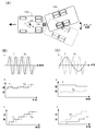
- FIG. 2A is a schematic plan view of an example of a vehicle when a sway state occurs.
- FIG. 2 (B) shows the time change (a) of the yaw rate and the lateral acceleration in the frequency band of the sway vibration when the sway state occurs, the time change (b) of the yaw rate vibration period and the lateral acceleration vibration period
- FIG. 2C shows the change (c) in the cumulative number of vibrations exceeding the predetermined threshold value of the lateral acceleration.
- FIG. 2C shows the yaw rate and lateral force in the frequency band of the sway vibration when the vehicle body rolls due to road disturbance or the like.
- FIGS. 3A, 3B, and 3C are phase diagrams showing a state in which the probability of occurrence of the sway state is high with the vibration state quantity of the yaw rate and the vibration state quantity of the lateral acceleration as variables.
- the probability of occurrence of the sway state is high in the hatched region, behavior control for suppressing the sway state is executed when the amplitude of the yaw rate or the lateral angle is large.
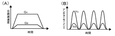
- FIG. 4A shows the target deceleration G A (when the possibility of occurrence of the sway state is high) and G B (when the occurrence of the sway state is uncertain) in the form of suppressing the sway state by deceleration of the vehicle. It is a figure showing the time change of).
- FIG. 4B shows the target anti-yaw moment Y A (when the possibility of occurrence of the sway state is high) and Y B (when the occurrence of the sway state is uncertain) in the form of suppressing the sway state by the generation of the anti-yaw moment. It is a figure showing a time change when it is.
- Diagram of the apparatus. 1 (A) of the vehicle 10 to a preferred embodiment of a device for executing the behavior control for the suppression of swaying state of the combination vehicle according to the present invention is mounted schematically shown.
- the vehicle 10 is shown in the figure by, for example, a connected vehicle that pulls any type of trailer, that is, a tractor 10a having a pair of front wheels 12f and a pair of rear wheels 12r, and a connector 14a provided at the rear of the tractor 10a.
- a trailer 10b having at least a pair of wheels 12t that are pivotably connected in the direction of the arrow.
- the vehicle is illustrated as a connected vehicle in which a passenger vehicle pulls a center axle type light trailer (such as a camping trailer, a cargo trailer, and a boat trailer) as an example.
- a center axle type light trailer such as a camping trailer, a cargo trailer, and a boat trailer
- the braking of each wheel of the tractor 10a of the connected vehicle 10 is performed by a braking system device 40 that can independently control the braking force of each wheel, as schematically shown in FIG.
- the braking system device 40 is typically an electronically controlled pneumatic braking system device, an air / hydraulic (combined) braking system device or a hydraulic braking system device, and the front wheel of the tractor 10a.
- a fluid pressure circuit 46 is provided for adjusting the brake pressure in the wheel cylinders 42fl, fr, rl, rr equipped on the 12fl, fr and the rear wheels 12rl, rr, that is, the braking force of each wheel of the tractor.
- the wheel cylinder of each wheel is selectively transferred to an air compressor, an air tank, a braking force booster, an oil pump, an oil reservoir, etc. (not shown) in a normal manner.
- Various valves (a modulator, a fluid pressure holding valve, a pressure reducing valve, etc.) that communicate with each other are provided, and in a normal braking operation, a brake valve (or master cylinder) 45 in response to the depression of the brake pedal 44 by the driver.
- motion control such as VSC
- sway suppression behavior control control for suppressing a sway state by the behavior control device of the present invention
- control of each wheel is performed.
- the various valves are operated based on the command of the electronic control unit 50 so that the brake pressure in the wheel cylinder of each wheel matches the target pressure. It is controlled individually.
- Brake lamps 30bl and br are provided at the rear of the tractor, and the ramps are provided with a predetermined deceleration when the brake pedal is depressed or when behavior control or other automatic braking force is applied. Lights when the value becomes larger than.
- a braking system device for braking each wheel of the trailer 10b may be provided.
- the brake system device of the trailer 10b may be an electromagnetic, inertial or fluid pressure type brake system device.
- the brake lamps 30bl and br of the tractor are turned on / off.
- the braking devices 42tl, tr equipped on the trailer wheels 12tl, tr are actuated so that a braking force is generated at each wheel (the braking force of each wheel can be selected selectively). It may be adjusted to (but not limited to).)
- Brake lamps 30btl and btr are also provided behind the trailer and light up together with the brake lamps of the tractor.
- the electronic control unit 50 may include a microcomputer having a CPU, a ROM, a RAM, and an input / output port unit connected to each other by a bidirectional common bus and a driving circuit.
- Brake pedal depression amount ⁇ b from a given depression amount sensor (not shown), wheel speed Vwi from a wheel speed sensor (not shown) provided for each wheel, and in the wheel cylinder of each wheel from a wheel cylinder pressure sensor
- the detected values such as the pressure Pbi, the lateral G sensor provided in the tractor, the lateral acceleration Gy from the yaw rate sensor 60, and the tractor yaw rate ⁇ are input.
- various detection signals representing various parameter values necessary for various controls to be executed in the vehicle of the present embodiment, such as longitudinal acceleration, may be input.
- the brake pedal depression amount sensor and the wheel cylinder pressure sensor for each wheel may not be provided.
- FIG. 1C shows the sway state suppression behavior control device of the present invention incorporated in the electronic control device 50 in the form of a block diagram.
- the lateral acceleration Gy detected by the lateral G sensor and the yaw rate ⁇ detected by the yaw rate sensor are respectively converted into the sway.
- the vibration state quantity (vibration state quantity calculation unit 50c) of the lateral acceleration Gy calculated from each of the components obtained by passing the signals through the bandpass filters (BPF) 50a and 50b that transmit signals in the vibration frequency band, and the yaw rate ⁇
- the vibration state quantity (vibration state quantity calculation unit 50d) is compared (comparison determination unit 50e), and based on the comparison result, the amplitude (amplitude detection unit 50f) detected from the component obtained by passing through the BPF 50b of the yaw rate ⁇ . ) Is large, it is determined whether or not the possibility of occurrence of a sway state is high (see notes 1 and 2 below).
- the vehicle speed determination unit 50g exceeds the predetermined speed, the sway state Target deceleration (braking force) or anti-yaw moment (yaw moment generated in antiphase with respect to yaw rate vibration) is determined (sway suppression behavior control unit 50h), target deceleration or anti-yaw moment Therefore, the braking force distribution is determined (braking force control unit 50i), and a control command is given to each braking device 46.
- the frequency range of sway vibration varies depending on the weight and arrangement of the load, vehicle speed, acceleration / deceleration, etc.
- the transmission band of the BPF may be set so as to cover frequencies that may occur.
- a component of the vehicle body slip angular velocity ⁇ ′ may be used instead of the component of the lateral acceleration Gy.
- the vibration state quantity of the lateral acceleration Gy (or the vehicle body slip angular velocity ⁇ ′) output from the vibration state quantity calculation unit 50c and the vibration state quantity calculation unit 50d.
- the possibility of occurrence of the sway state is high in the comparison result with the vibration state amount of the output yaw rate ⁇ , the possibility of occurrence of the sway state is high in the sway suppression behavior control unit 50h.
- a control amount lower than the time, that is, a low target deceleration or a small anti-yaw moment is determined, and braking force distribution is determined to achieve the target deceleration or anti-yaw moment (braking force control unit 50i).
- a control command is given to the fluid pressure circuit 46.
- control for reducing the output of the drive device may be executed for the purpose of decelerating the vehicle.
- a signal is given from the sway suppression behavior control unit 50h to the driving force control 50j, and an instruction to reduce the output of the driving device is given.
- the output reduction of the driving device is not executed.
- the above-described units 50a to 50j are realized by processing operations of the CPU and other elements in accordance with a program stored in advance in a storage device such as a memory in the electronic control unit 50. .
- FIG. 2A illustrates the principle of the apparatus due to various factors such as sudden steering, excessive vehicle speed, crosswind, or imbalance in load distribution while the coupled vehicle 10 is traveling as illustrated in FIG.
- the trailer 10b may swing or vibrate like a pendulum in the yaw direction with the coupler 14a of the tractor 10a as a fulcrum (sway vibration).
- sway vibration of the trailer causes coupled vibration of the tractor 10a, the amplitudes of the yaw rate ⁇ and the lateral acceleration Gy (or the vehicle body slip angular velocity ⁇ ′) of the tractor 10a are increased, and the stability of the vehicle is deteriorated. .
- the amplitude of the sway vibration frequency band component of the tractor yaw rate ⁇ or lateral acceleration Gy (or vehicle body slip angular velocity ⁇ ′) is monitored, and the amplitude increases.
- a sway state a state in which sway vibration is occurring
- the vehicle is decelerated, or the tractor yaw rate or lateral acceleration Gy (or vehicle body slip angular velocity ⁇ ′) is suppressed in a direction to suppress vibration ( That is, the sway state is suppressed by the generation of the yaw moment (in the opposite phase) (see cited document 2).
- the amplitude of the frequency band component of the sway vibration of the yaw rate ⁇ or the lateral acceleration Gy (or the vehicle body slip angular velocity ⁇ ′) of the tractor is the same even if the sway state does not occur.
- simply monitoring the amplitude of the yaw rate ⁇ or the lateral acceleration Gy (or the vehicle body slip angular velocity ⁇ ′) makes it possible to detect the sway state. It has been found difficult to detect the occurrence.
- the vibration speed of the sway vibration frequency band component of the yaw rate ⁇ of the tractor and the lateral acceleration Gy (or the vehicle body slip angular velocity ⁇ ′), that is, the vibration frequency, Where the vibration period and the like are substantially equal see FIG. 2 (B) a
- the tractor yaw rate ⁇ and lateral acceleration Gy or vehicle body slip angular velocity Although the amplitude of ⁇ ′ can be increased, it has been found that the vibration speeds of yaw rate ⁇ and lateral acceleration Gy (or vehicle body slip angular velocity ⁇ ′) are different from each other (see FIG. 2 (C) a).
- the vibration state quantities of the yaw rate ⁇ and the lateral acceleration Gy can be substantially different from each other due to the influence of the vehicle body roll caused by the road surface disturbance or the like. That is, when the vibration state quantities of the yaw rate ⁇ and the lateral acceleration Gy (or the vehicle body slip angular velocity ⁇ ′) are substantially different, it cannot be said that the sway state is not always generated.
- the apparatus according to the present embodiment has the yaw rate ⁇ and the lateral acceleration Gy (or the vehicle body slip angular velocity ⁇ ′) when the amplitude of the component of the frequency band of the sway vibration of the yaw rate ⁇ or the lateral acceleration Gy (or the vehicle body slip angular velocity ⁇ ′) increases.
- the vibration state quantities of the yaw rate ⁇ and the lateral acceleration Gy (or the vehicle body slip angular velocity ⁇ ′) are substantially different, that is, even in the presence of the vehicle body rolling due to road disturbance or the like.
- the behavior control is executed at a weak level, for example, at least at a minimum level, and the sway vibration is generated, it is expected that the development is suppressed and the operation is performed. Since the degree of behavior control executed independently of the driver's operation is weaker than usual, it is advantageous in that the influence on the driver's operation or the surroundings of the vehicle can be reduced.
- the behavior control for detecting the possibility of occurrence of the sway state of the operation trailer of the apparatus and for suppressing the sway state may be roughly divided into the following processes.
- (iii) Behavior control for sway state suppression Each process is described in detail below. Explained.
- the vibration state quantity calculation unit measures a time interval in which the value of the input component passes through 0 point, that is, a half cycle of vibration, and outputs the value. Then, when the vibration of the yaw rate value ⁇ and the vibration of the lateral acceleration value Gy (or the vehicle body slip angular velocity value ⁇ ′) are caused by the sway vibration, as illustrated in FIG.
- the vibration period of the acceleration Gy (or the vehicle body slip angular velocity ⁇ ′) and the vibration period of the yaw rate ⁇ change substantially equally.
- the vibration of the yaw rate value ⁇ and the vibration of the lateral acceleration value Gy (or the vehicle body slip angular velocity value ⁇ ′) are caused by the vehicle body rolling due to a road surface disturbance, as illustrated in FIG.
- the vibration cycle of the lateral acceleration Gy (or the vehicle body slip angular velocity ⁇ ′) and the vibration cycle of the yaw rate ⁇ are substantially different. Therefore, as will be described later, by referring to the comparison results of these vibration periods, sway vibration may occur when an increase in yaw rate amplitude is detected in the process (ii) described later. Whether or not the property is high can be determined.
- the vibration state quantity calculation unit When the number of vibrations within a predetermined time is used as the vibration state quantity, first, similarly to the above, the lateral acceleration value Gy (or the vehicle body slip angular velocity value ⁇ ′) and the yaw rate value ⁇ are respectively passed through the BPFs 50a and 50b. Sway vibration frequency band components are extracted, and the extracted components are given to the vibration state quantity calculation units 50c and 50d, respectively. In the vibration state quantity calculation unit, the cumulative number when the value of the input component exceeds a predetermined threshold (that is, the cumulative number of occurrences of large amplitude) is counted and the cumulative number is output (the cumulative number) Is reset when the value of the component input over a predetermined time does not exceed a predetermined threshold value).
- a predetermined threshold that is, the cumulative number of occurrences of large amplitude
- the vibration state quantities of the yaw rate ⁇ and the lateral acceleration Gy (or the vehicle body slip angular velocity ⁇ ′), that is, the vibration period or frequency are calculated, those values are given to the comparison determination unit 50e.
- the deviation of the vibration state quantity is inspected, and the high possibility of occurrence of the sway state is determined. Specifically, when any of the following conditions is satisfied, it may be determined that the possibility of occurrence of the sway state is high.
- the ratio of the vibration state quantity S ( ⁇ ) of the yaw rate ⁇ to the vibration state quantity S (Gy) of the lateral acceleration Gy (or the vibration state quantity S ( ⁇ ′) of the vehicle body slip angular velocity ⁇ ′) is a predetermined value including 1.
- Spb-Spt that is, Spb ⁇ S ( ⁇ ) / S (Gy) ⁇ Spt (1)
- the conditions (a) to (c) described above are the vibration state quantity S ( ⁇ ) of the yaw rate ⁇ and the vibration state quantity S (Gy) of the lateral acceleration Gy (or the vibration state of the vehicle body slip angular velocity ⁇ ′. This is a condition for determining that the amount S ( ⁇ ′)) is not substantially different.
- the comparison / determination unit 50e which of the above conditions (a) to (c) is adopted may be appropriately selected by a designer, and both cases belong to the present invention.
- Each value, Sdo, Spb, Spt is set experimentally or theoretically according to the type and specification of the vehicle.
- the yaw rate value ⁇ obtained from the yaw rate sensor is first passed through the BPF 50b to extract the frequency band component of the yaw rate sway vibration, and the amplitude It is input to the detection unit 50f.
- the amplitude detection unit 50f includes a counter that counts the number of times that the magnitude of the input yaw rate component exceeds a predetermined threshold within a predetermined time (that is, the number of occurrences of large amplitude). When the predetermined number of times is reached, that is, when the amplitude of the yaw rate component increases over a predetermined period, a signal indicating this is generated.
- the amplitude detector 50f changes the “predetermined threshold value” and / or the “predetermined number of times” according to the presence / absence of a signal indicating that the possibility of occurrence of the sway state is high from the comparison / determination unit 50e. It may be. That is, when a signal indicating that the possibility of occurrence of a sway state is high is received, the above-mentioned “predetermined threshold” and / or “predetermined number of times” are set lower than when such a signal is not received.
- the comparison determination unit 50e determines that the possibility of occurrence of the sway state is high, the yaw rate component of the frequency band of the sway vibration is more quickly (before the amplitude of the yaw rate component becomes considerably large). An increase in amplitude is detected. Note that when the sway state of the trailer occurs, the amplitude of the lateral acceleration or the vehicle body slip angular velocity also increases. Therefore, instead of detecting the increase in the yaw rate amplitude, an increase in the amplitude of the lateral acceleration Gy or the vehicle body slip angular velocity ⁇ ′ is detected. It may be like this.
- the comparison determination unit 50e does not issue a signal indicating that the possibility of occurrence of the sway state is high, that is, the vibration state quantity S ( ⁇ ) of the yaw rate ⁇ and the vibration state quantity S (Gy)
- the vibration state quantity S ( ⁇ ) of the yaw rate ⁇ and the vibration state quantity S (Gy) Alternatively, when the amplitude of the frequency band component of the sway vibration of the yaw rate of the tractor increases in a state where the vibration state quantity S ( ⁇ ′)) of the vehicle body slip angular velocity ⁇ ′ is substantially different, the increase in the amplitude is It cannot be determined whether it is due to sway vibration or due to rolling of the vehicle body caused by road disturbance.
- the sway suppression behavior control unit 50h refers to the signal from the comparison determination unit 50e and the signal from the amplitude detection unit 50f, and detects a signal and amplitude detection from the comparison determination unit 50e indicating that the possibility of occurrence of the sway state is high.
- a signal indicating an increase in the amplitude of the yaw rate value is received from the unit 50f, the execution of behavior control for suppressing the sway state using the first control amount is instructed, and the sway state can be generated from the comparison determination unit 50e.
- a sway using a second control amount lower than the first control amount is received. Instructs execution of behavior control for state suppression. However, when the vehicle speed is lower than the predetermined speed, the behavior control may not be executed in any case. Specifically, the behavior control for suppressing the sway state may be executed by deceleration of the vehicle and / or generation of an anti-yaw moment.
- the sway suppression behavior control unit 50h When the sway state suppression is executed by the deceleration of the vehicle, the sway suppression behavior control unit 50h generates a sway state from the comparison determination unit 50e in response to receiving a signal indicating an increase in the amplitude of the yaw rate value from the amplitude detection unit 50f.
- the potential is receiving a signal indicating a high that sets a target deceleration G a such is illustrated in FIG. 4 (a), so that the target deceleration G a is reached, the braking force
- the controller 50i is instructed to increase the braking force of each wheel, or at the same time, the driving force control unit 50j of the vehicle is reduced in driving output (reduction in throttle opening or torque output). Instruct.
- the sway suppression behavior control unit 50h receives a signal indicating an increase in the amplitude of the yaw rate value from the amplitude detection unit 50f
- the sway suppression behavior control unit 50h receives a signal indicating that a sway state is highly likely to occur from the comparison determination unit 50e.
- the target decelerations G A and G B are: G A > G B (4) Is set to hold.
- G A is the vehicle speed, based on the amplitude or the like of the yaw rate value may be set by any method.
- G A is required as the target deceleration, the generation of swaying state is assumed to be substantially reliable, G A is as soon as possible the swaying state converges while ensuring the safety of the vehicle traveling It is preferable to set the size sufficiently large.
- G B is required as the target deceleration, causes the amplitude of the increase in the yaw rate value is a roll of the vehicle body due to road surface disturbance or the like, occurrence of sway oscillations is uncertain.
- G B is operation of the driver, is preferably set to lower excessive impact on the surrounding vehicle of about beyond the value (> 0).
- the brake lamp degree of may be set to a value (which is not lit, giving unnecessary warnings to the driver of a vehicle traveling behind the host vehicle is avoided. Such deceleration processing May be continued until the signal indicating the increase in the amplitude of the yaw rate from the amplitude detector disappears.
- the sway state suppression frequency control component 50h Referring to this, a target value of anti-yaw moment having an opposite phase to that component is calculated, and the value is transmitted to braking force control unit 50i. At that time, when receiving a signal indicating a high likelihood of sway state generated from the comparison determination unit 50e is set to a value The illustrated such anti yaw moment Y A in FIG.
- a small Y B amplitude is set than the anti-yaw moment Y a.
- the amplitude of Y A is after securing the safety of the vehicle traveling It is preferable that the amplitude is set to a magnitude that is sufficient for the sway state to converge as quickly as possible.
- the anti-yaw moment Y B is required, the presence or absence of occurrence of sway vibration is uncertain.
- the amplitude of B is preferably set to a low amplitude (> 0) that does not excessively affect the driver's operation and the surroundings of the vehicle.
- the braking force control unit 50i determines the braking force distribution of each wheel to achieve the anti-yaw moment, and controls the braking device 46 according to the determined braking force distribution.
- a command is given and an anti-yaw moment is generated.
- the generation of the anti-yaw moment may be continued until the signal indicating the increase in the amplitude of the yaw rate from the amplitude detector disappears.
- the behavior control by the anti-yaw moment also has an effect of suppressing instability of the vehicle due to road surface disturbance or the like, so even if it is executed with Y A as the target value regardless of the presence or absence of a signal from the comparison determination unit 50e. Good.
- the occurrence of the sway state is uncertain, considering that the sway state can occur even in the presence of rolling of the vehicle body due to road surface disturbance, etc.
- the control effect is obtained at least at the minimum level, and the sway vibration is obtained. Attempts are made to reduce the delay in the execution of amplification or behavior control.
- the vibration state quantity calculation unit calculates the vibration state quantity based on the vibration state quantity. Therefore, when the number of vibrations reaches a predetermined number, it may be determined that the amplitude of those values has increased. Therefore, in this case, the sway suppression control may be executed when the comparison determination unit 50e issues a signal (in this case, the vibration detection unit 50f is omitted).
- condition for determining the vibration state quantity illustrated in the phase diagram in FIG. 3 (the shape of the phase diagram in FIG. 3) is not limited to the illustrated example, and other conditions may be used. It should be understood that such a case also belongs to the scope of the present invention.
- the most important feature of the present invention is that the action of the sway state suppression behavior control is changed depending on whether the speed or frequency of vibration of the yaw rate is substantially equal to the speed or frequency of vibration of the lateral acceleration or the vehicle body slip angular velocity. Therefore, the method for determining whether the speed or frequency of the yaw rate vibration and the vibration speed or frequency of the lateral acceleration or the vehicle body slip angular velocity are substantially equal is a method different from that exemplified in the embodiment. Such a case may be included in the scope of the present invention.
- the determination of the occurrence of the sway state or the control of the sway state suppression behavior is performed based on the homology between the frequency distribution (spectrum) of the yaw rate in the sway vibration frequency band component and the lateral acceleration or the vehicle body slip angular velocity frequency distribution. Good.
Landscapes
- Engineering & Computer Science (AREA)
- Transportation (AREA)
- Mechanical Engineering (AREA)
- Regulating Braking Force (AREA)
Abstract
トラクタとトレーラとを含む連結車両のスウェイ状態抑制のための挙動制御装置であって、路面外乱等に起因する車体の横揺れとトレーラのスウェイ状態との判定が困難なときでも、運転者の操作に過度な影響が与えられない範囲で或る程度のスウェイ状態抑制効果が確保できるよう構成された装置が提供される。本発明の装置は、トラクタのヨーレートの振動状態量とトラクタの横加速度又は車体スリップ角速度の振動状態量との関係から連結車両のトレーラのスウェイ状態の発生の可能性が高いと判定されていない場合であっても、低い制御量にてスウェイ状態抑制のための挙動制御を実行する。
Description
本発明は、自動車等の車両の挙動制御に係り、より詳細には、トラクタがトレーラを牽引する形式の連結車両に於けるスウェイ状態(スネーキング運動、トレーラの振り子運動とも称される。)の抑制並びに車両挙動安定化のための挙動制御装置に係る。
フルトレーラ又はセミトレーラの形式の連結車両では、一般に、トラクタに牽引されるトレーラが、トラクタの後部に設けられたピン又はカプラにより枢動可能に連結されている。このような形式の連結車両の走行中に於いて、急操舵、車速過大、横風或いは積載物の配分の不均衡等の種々の要因により、トレーラの「スウェイ状態」、即ち、トレーラがトラクタに対してピン又はカプラ(枢動軸)周りにヨー方向に揺動又は振動した状態、が惹起されることがある(図2(A)参照)。かかるトレーラのスウェイ状態が発生すると、トラクタもヨー方向に振動することとなり、車両挙動が不安定となる。そこで、そのようなスウェイ状態の抑制のための車両挙動安定化制御装置が種々提案され、実用化されている。例えば、特許文献1に於いては、トラクタとトレーラとの連結角(ヒッチ角)が所定角度に達するとトレーラブレーキを作動し、これにより、トレーラの制動力によってトレーラに於いてヒッチ角を低減する方向にヨーモーメントを発生する制御装置が開示されている。また、特許文献2は、スウェイ状態に於ける周波数帯域のヨーレート、車両の横加速度の大きさが所定値に達したか否かを監視することによりにスウェイ状態の発生を検出すること、そして、制動力配分制御によりヨーレート及び/又は横加速度の位相と逆位相のヨーモーメントを生成することによりスウェイ状態を抑制することを開示している。更に、特許文献3では、スウェイ状態の抑制のための安定化制御に於いて、トレーラの牽引時のトラクタの検出されたヨーレートと車両モデルに基づくヨーレートとの偏差によってスウェイ状態の評価を行うこと、及び、ヨーレート偏差と横加速度の周波数のずれと位相のずれとがそれぞれ大きいときには、スウェイ状態が発生しているとの識別を禁止し、走行安定化制御を実施しないことが提案されている。
特開平10-236289号公報
国際公開2001/002227
国際公開2004/041612
上記の如き連結車両のスウェイ状態抑制のための挙動制御装置は、スウェイ状態の検出が為されると、制動力の付与による車両の減速やアンチヨーモーメントの発生などの挙動制御を自動的に実行する。従って、かかる運転者の運転操作とは無関係な制動力の付与を不要に実行することを回避するためには、スウェイ状態の検出の精度をできるだけ向上させることが好ましい。この点に関し、通常、スウェイ状態の検出は、スウェイ振動の増大に伴うヨーレートや横加速度など、車両の揺れの大きさ及び頻度が反映される物理特性値のスウェイ振動帯域の成分の振幅の増大を検知して為されている。しかしながら、スウェイ振動帯域の成分の振幅の増大は、路面外乱、即ち、路面が荒れていることなどに起因して車体が揺れるだけでも生ずることあり、その場合、スウェイ振動が大きくなっていないにもかかわらず、制動力の付与による車両の減速又はアンチヨーモーメントの発生が実行される場合があり得る。そこで、従前では、スウェイ状態抑制制御の作動の不要な又は時期尚早な開始を回避するために、スウェイ状態の発生判定のためのヨーレートや横加速度の振幅の閾値を高くするといった措置が取られていた(当然、そのような場合には、スウェイ状態抑制制御作動開始が遅れることと成り得る。)。また、スウェイ状態の発生時には、ヨーレートの振動状態(振動の頻度、周波数、周期など)と横加速度又は車体スリップ角速度の振動状態が略同じとなるのに対し、路面外乱等により単に車体の横揺れが発生したときには、ヨーレートの振動状態と横加速度又は車体スリップ角速度の振動状態とが相異することが見出され、この知見に基づいて、ヨーレートと横加速度又は車体スリップ角速度との振動状態の比較結果に基づいてスウェイ状態発生の可能性が低いと判断されるときには、車両の減速又はアンチヨーモーメントの付与が実行されにくくするといった制御手法が提案された(例えば、本願出願人による国際特許出願PCT/JP2000/67500参照)。
しかしながら、路面外乱等に起因した車体の揺れが発生している際にもスウェイ状態が発生することがあり、路面外乱等に起因した車体の揺れの寄与が比較的大きいときには、実際にはスウェイ振動が発生しているにもかかわらず、ヨーレートと横加速度又は車体スリップ角速度との振動状態の比較結果に於いて、スウェイ状態の発生の可能性が低いとの判定が為されることがあり得る。従って、ヨーレートの振動状態と横加速度又は車体スリップ角速度の振動状態とが異なっていることに基づいてスウェイ状態発生の可能性が低いと判断し、スウェイ状態抑制のための車両の減速又はアンチヨーモーメントの付与が実行されにくくなっていると、路面外乱等に起因した車体の揺れの大きいときには、スウェイ状態抑制制御が遅れる可能性がある。
かくして、本発明の一つの課題は、連結車両のスウェイ状態抑制のための挙動制御装置であって、路面外乱等に起因する車体の横揺れとトレーラのスウェイ状態との判定が困難なときでも、スウェイ状態抑制制御が遅れる影響を低減できるよう構成された装置を提供することである。
また、本発明のもう一つの課題は、上記の如き装置であって、車体の横揺れがあったときには、運転者の操作に過度な影響が与えられない範囲で少なくとも或る程度のスウェイ状態抑制効果が確保できるよう構成された装置を提供することである。
本発明によれば、上記の課題を達成するために、トラクタと該トラクタにより牽引されるトレーラとを含む連結車両のスウェイ状態を抑制するべく少なくとも一つの車輪に制動力を付与する挙動制御装置であって、トラクタのヨーレートの振動状態量とトラクタの横加速度又は車体スリップ角速度の振動状態量との関係に基づいて前記の少なくとも一つの車輪に付与される制動力が変更される装置が提供される。ここに於いて、少なくとも一つの車輪に付与される制動力により達成される制御は、具体的には、車両の減速、スウェイ状態を抑制する方向へのヨーモーメント(アンチヨーモーメント)の生成のいずれであってもよい。車輪に付与される制動力は、基本的には、各輪の制動装置により与えられる制動力であってよいところ、一部が車両の駆動装置の出力の低下(エンジンのスロットル開度の低減、回生制動等)により生成されてもよいことは理解されるべきである。また、「振動状態量」とは、各々の物理量の振動の速さを表す任意の指標値、例えば、振動の頻度、周波数、周期などであってよい。
既に触れた如く、トレーラのスウェイ振動の周波数帯域に於けるトラクタのヨーレート又は横加速度若しくは車体スリップ角速度の成分の振幅の増大時のトレーラのスウェイ振動が発生しているか否かの可能性は、基本的には、ヨーレートの振動状態と横加速度又は車体スリップ角速度の振動状態との関係を参照することにより推定可能である。しかしながら、路面外乱等が比較的大きいときには、それによる車体の横揺れがヨーレートの振動状態と横加速度又は車体スリップ角速度の振動状態との関係に強く反映され、スウェイ振動発生の有無についての精度の良い判定は困難となる。そして、ヨーレートの振動状態と横加速度又は車体スリップ角速度の振動状態との関係に基づいてスウェイ振動の発生の可能性が低いと判定されるときに、挙動制御が実行されない場合或いは実行されにくくなっている場合には、抑制効果の遅れが生じ得る。他方、ヨーレートと横加速度(又は車体スリップ角速度)の振動状態との関係を用いずにスウェイ振動の周波数帯域に於けるトラクタのヨーレート又は横加速度若しくは車体スリップ角速度の成分の振幅の増大だけに応答してスウェイ状態抑制のための挙動制御を実行することは、運転者の操作とは独立した制動力の過度の付与となり得るため、好ましくない。そこで、本発明の挙動制御装置は、上記の如く、トラクタのヨーレートの振動状態量とトラクタの横加速度又は車体スリップ角速度の振動状態量との関係に基づいてスウェイ状態抑制のための挙動制御の制御量、即ち、少なくとも一つの車輪に付与される制動力を変更するよう構成され、これにより、スウェイ状態抑制のための挙動制御による制動力の過度の付与を回避しつつ、路面外乱等が比較的大きいときにスウェイ状態が発生した場合にも抑制効果の遅れをできるだけ少なくすることが試みられる。
上記に於いて、路面外乱等が比較的大きいときにスウェイ状態が発生した場合にも抑制効果の遅れをできるだけ少なくするためのより具体的な構成として、本発明の装置は、ヨーレートの振動状態量と横加速度又は車体スリップ角速度の振動状態量との関係に基づいてスウェイ状態の発生の可能性が高いと判定されていない場合には、スウェイ状態の発生の可能性が高いと判定される場合よりも低い制御量にてスウェイ状態抑制のための挙動制御を実行するよう構成されていてよい。即ち、路面外乱等が比較的大きく、これにより、スウェイ状態の発生の可能性が不確定と判定される場合(従前では、スウェイ状態の発生の可能性が低いと判定される場合)であっても、或る程度の制御量にてスウェイ状態抑制のための挙動制御を実行しておくことによって、車両の安定化を図り、スウェイ状態の進行の抑制が図ることが可能となる。
また、既に述べた如く、トレーラのスウェイ振動の周波数帯域に於けるヨーレートの振動状態と横加速度又は車体スリップ角速度の振動状態とが実質的に異なるときには、基本的には、スウェイ状態が発生していない可能性が高いことが見出されている(「実質的に異なる」とは、二つの振動状態量に於いて有意な差があることを意味し、「実質的に等しい」とは、二つの振動状態量に於いて有意な差がないことを意味する。)。従って、上記の装置は、トレーラのスウェイ振動の周波数帯域に於けるトラクタのヨーレートの成分の振動状態量とトラクタの横加速度又は車体スリップ角速度の成分の振動状態量とが実質的に異なるときには、前記二つの振動状態量が実質的に等しいときに比して低い制御量にて挙動制御を実行するようになっていてよい。その場合、具体的には、アンチヨーモーメントの生成によりスウェイ状態を抑制する構成に於いては、低い制動力にてトラクタのヨーレートを減衰し、車両の減速によりスウェイ状態を抑制する構成に於いては、低い目標減速度にて車両が減速されることとなる。
上記の本発明の実施の態様に於いて、挙動制御装置は、トレーラのスウェイ振動の周波数帯域に於けるトラクタのヨーレート又は横加速度若しくは車体スリップ角速度の成分の振幅が所定値より大きい状態が所定時間継続したときに目標減速度が達成されるよう少なくとも一つの車輪に制動力を付与する手段を含み、トラクタのヨーレートの振動状態量とトラクタの横加速度又は車体スリップ角速度の振動状態量とが実質的に異なるときには、トラクタのヨーレートの振動状態量とトラクタの横加速度又は車体スリップ角速度の振動状態量とが実質的に等しいときに比して、前記の制動力が低減される装置であってよい。これにより、スウェイ状態発生の可能性が高いときには、相対的に高い制動力によりスウェイ状態が迅速に抑制されることが期待される一方、スウェイ状態発生の有無が不確定であると判断されるときであっても、或る程度のスウェイ状態抑制の制御効果を確保することが可能となる。
また、スリップ状態抑制の挙動制御の実行に際して、目標減速度を設定して車両の減速を行う形式に於いては、一つの態様として、本発明の挙動制御装置は、トラクタのヨーレートの振動状態量とトラクタの横加速度又は車体スリップ角速度の振動状態量とが実質的に等しいときには、第一の目標減速度にて車両を減速し、トラクタのヨーレートの振動状態量とトラクタの横加速度又は車体スリップ角速度の振動状態量とが実質的に異なるときには、第一の目標減速度よりも低い第二の目標減速度にて車両を減速するよう構成されていてよい。
上記の構成に於いて、ヨーレートの振動状態量と横加速度又は車体スリップ角速度の振動状態量とが実質的に等しいか否かは、二つの振動状態量の比又は差により判定されてよい。振動状態量の一つの例として、対応する物理量の振動周期が採用される場合には、少なくとも一つの車輪に付与される制動力の変更は、トラクタのヨーレートの振動周期とトラクタの横加速度又は車体スリップ角速度の振動周期との比又は差に基づいて為されるようになっていてよい。また、振動状態量のもう一つの例として、対応する物理量の所定時間に於ける所定の大きさを超える振動回数(振動の頻度)が採用される場合には、少なくとも一つの車輪に付与される制動力の変更は、所定時間に於けるトラクタのヨーレートの振動回数とトラクタの横加速度又は車体スリップ角速度の振動回数との比又は差に基づいて為されるようになっていてよい。典型的には、トレーラのスウェイ振動の周波数帯域に於けるトラクタのヨーレートの成分の振動状態量とトレーラのスウェイ振動の周波数帯域に於けるトラクタの横加速度又は車体スリップ角速度の成分の振動状態量との比又は差が所定範囲内にないとき(トラクタのヨーレートの振動状態量とトラクタの横加速度又は車体スリップ角速度の振動状態量とが実質的に異なるとき)には、挙動制御のために少なくとも一つの車輪に付与される制動力が、前記の比又は差が前記の所定範囲内にあるとき(トラクタのヨーレートの振動状態量とトラクタの横加速度又は車体スリップ角速度の振動状態量とが実質的に等しいとき)よりも低く設定されるようになっていてよい。ここで、「所定範囲」とは、振動状態量の差又は比がその範囲にあれば、ヨーレート及びトラクタの横加速度若しくは車体スリップ角速度の振動状態量に於いて有意な差異がないと判断される範囲に定められる。なお、スウェイ状態の発生の可能性が不確定と判定される場合に、或いは、トラクタのヨーレートの振動状態量とトラクタの横加速度又は車体スリップ角速度の振動状態量とが実質的に異なるときに、或いは、ヨーレートの振動状態量と横加速度又は車体スリップ角速度の成分の振動状態量との比又は差が所定範囲内にないときに実行される挙動制御(制動力の付与)の程度は、例えば、車両のブレーキランプが点灯しない程度であってよい。これは、スウェイ状態の発生の可能性が低いと判定される場合に実行される挙動制御に伴うブレーキランプの点灯によって、車両の後方の別の車両の運転者を驚かせてしまうことを回避するためである。
かくして、上記の本発明の装置によれば、ヨーレートの振動状態と横加速度又は車体スリップ角速度の振動状態との関係を参照して、スウェイ状態抑制のための挙動制御に於ける制御量を変更することにより、路面外乱等に起因する車体の横揺れとトレーラのスウェイ状態との判定が困難なときであっても、運転者の操作とは独立の制動力付与の過剰な実行と制御の開始の遅れとの双方を低減することが可能となる。上記の本発明の構成に於いては、トレーラのスウェイ振動の周波数帯域に於けるトラクタのヨーレート又は横加速度若しくは車体スリップ角速度の成分の振幅が所定値より大きい状態が所定時間継続したとき、二つの振動状態量の関係からはスウェイ状態の発生の可能性が高いと判定されていない場合であっても、完全に挙動制御の実行を止めてしまうのではなく、或る程度の制御量にて挙動制御を実行することが可能となっているので、少なくとも運転者の操作に過度な影響が与えられない範囲でのスウェイ状態抑制効果の確保が可能となり、スウェイ状態抑制制御の過剰な又は時期尚早の実行の回避のための措置に起因した制御開始の遅れも解消され、連結車両の挙動安定性・安全性が改善されることが期待される。また、本発明の装置によれば、スウェイ状態抑制制御は、専用のセンサ手段(例えば、連結ピンのヒッチ角を検出するセンサなど)を用いずに、通常の挙動制御装置の作動のために使用されるセンサ群から検出されるパラメータを用いて実行可能であるので、コストの増大が抑えられる点で有利である。
本発明のその他の目的及び利点は、以下に於いて、部分的に明らかになり、指摘される。
10…車両
10a…トラクタ
10b…トレーラ
12fl、fr…トラクタ前輪
12rl、rr…トラクタ後輪
12tl、tr…トレーラ車輪
14a…連結ピン
30bl、br、btl、btr…ブレーキランプ
40…制動系装置
42fl、fr、rl、rr…ホイールシリンダ
42tl、tr…トレーラ車輪制動装置
44…ブレーキペダル
45…ブレーキバルブ又はマスタシリンダ
46…流体圧回路(トラクタ)
46t…制動装置(トレーラ)
50…電子制御装置
60…横加減速度センサ、ヨーレートセンサ(トラクタ)
10a…トラクタ
10b…トレーラ
12fl、fr…トラクタ前輪
12rl、rr…トラクタ後輪
12tl、tr…トレーラ車輪
14a…連結ピン
30bl、br、btl、btr…ブレーキランプ
40…制動系装置
42fl、fr、rl、rr…ホイールシリンダ
42tl、tr…トレーラ車輪制動装置
44…ブレーキペダル
45…ブレーキバルブ又はマスタシリンダ
46…流体圧回路(トラクタ)
46t…制動装置(トレーラ)
50…電子制御装置
60…横加減速度センサ、ヨーレートセンサ(トラクタ)
以下に添付の図を参照しつつ、本発明を幾つかの好ましい実施形態について詳細に説明する。図中、同一の符号は、同一の部位を示す。
装置の構成
図1(A)は、本発明による連結車両のスウェイ状態の抑制のための挙動制御を実行する装置の好ましい実施形態が搭載される車両10を概略的に示している。車両10は、例えば、任意の形式のトレーラを牽引する連結車両、即ち、一対の前輪12f及び一対の後輪12rを有するトラクタ10aと、トラクタ10aの後部に設けられた連結器14aにて図中の矢印の方向に枢動可能に連結された少なくとも一対の車輪12tを有するトレーラ10bとから成る連結車両であってよい。なお、図では、車両は、一つの例として、乗用車がセンターアクスル式ライトトレーラ(キャンピングトレーラ、カーゴトレーラ、ボートトレーラなど)を牽引する連結車両として描かれているが、本発明の装置は、トラクタとトレーラとが互い枢動可能に連結され、従って、スウェイ状態が発生し得る任意の形式のトラック(フルトレーラ型又はセミトレーラ型であってよい。)、バス等の車両に適用されてよく、そのような場合も本発明の範囲に属することは理解されるべきである。
図1(A)は、本発明による連結車両のスウェイ状態の抑制のための挙動制御を実行する装置の好ましい実施形態が搭載される車両10を概略的に示している。車両10は、例えば、任意の形式のトレーラを牽引する連結車両、即ち、一対の前輪12f及び一対の後輪12rを有するトラクタ10aと、トラクタ10aの後部に設けられた連結器14aにて図中の矢印の方向に枢動可能に連結された少なくとも一対の車輪12tを有するトレーラ10bとから成る連結車両であってよい。なお、図では、車両は、一つの例として、乗用車がセンターアクスル式ライトトレーラ(キャンピングトレーラ、カーゴトレーラ、ボートトレーラなど)を牽引する連結車両として描かれているが、本発明の装置は、トラクタとトレーラとが互い枢動可能に連結され、従って、スウェイ状態が発生し得る任意の形式のトラック(フルトレーラ型又はセミトレーラ型であってよい。)、バス等の車両に適用されてよく、そのような場合も本発明の範囲に属することは理解されるべきである。
連結車両10のトラクタ10aの各輪の制動は、図1(B)に模式的に示されている如き、各輪の制動力を独立に制御することのできる制動系装置40により行われる。端的に述べれば、制動系装置40は、典型的には、電子制御式の空気圧式制動系装置、空気・油圧式(複合式)制動系装置又は油圧式制動系装置であり、トラクタ10aの前輪12fl、fr及び後輪12rl、rrに装備をされたホイールシリンダ42fl、fr、rl、rr内のブレーキ圧、即ち、トラクタ各輪の制動力、を調節する流体圧回路46を含む。トラクタ10aの流体圧回路46には、通常の態様にて、各輪のホイールシリンダを、選択的に、エアコンプレッサ、エアタンク、制動力倍力装置、オイルポンプ、オイルリザーバ等(図示せず)へ連通する種々の弁(モジュレータ、流体圧保持弁、減圧弁等)が設けられ、通常の制動作動に於いては、運転者によるブレーキペダル44の踏込みに応答してブレーキバルブ(又はマスタシリンダ)45が作動し、エアタンク、制動倍力装置又はマスタシリンダの圧力がそれぞれのホイールシリンダ42i(i=fl、fr、rl、rr 以下同様)へ供給され、各輪に一斉に制動力が発生される。しかしながら、ABS制御、VSC等の運動制御、本発明の挙動制御装置によるスウェイ状態を抑制するための制御(スウェイ抑制挙動制御)又はその他の任意の制動力配分制御を実行するべく、各輪の制動力を個別に又は独立に調節する場合には、電子制御装置50の指令に基づいて、前記の種々の弁が作動され、各輪のホイールシリンダ内のブレーキ圧がそれぞれの目標圧に合致するよう個別に制御される。また、トラクタの後方には、ブレーキランプ30bl、brが備えられ、ランプは、ブレーキペダルの踏込みがあったとき、或いは、挙動制御又はその他の自動的な制動力の付与により車両の減速度が所定の値より大きくなったときに点灯する。
また、任意に、トレーラ10bの各輪を制動するための制動系装置が設けられていてよい。トレーラ10bの制動系装置は、電磁式、慣性式或いは流体圧式の制動系装置であってよく、例えば、電子制御装置50の指令に基づいて、トラクタのブレーキランプ30bl、brのON/OFF状態に対応して、トレーラ車輪12tl、trに装備をされた制動装置42tl、trが作動し、それぞれの車輪に於いて制動力が発生するようになっていてよい(各輪の制動力は、選択的に調節されるようになっていてもよいが、それに限定されない。)。なお、トレーラ10bは、制動系装置が装備されていないものであってもよく、そのような場合も本発明の範囲に属することは理解されるべきである。トレーラの後方にもブレーキランプ30btl、btrが備えられ、トラクタのブレーキランプと伴に点灯する。
電子制御装置50は、通常の形式の、双方向コモン・バスにより相互に連結されたCPU、ROM、RAM及び入出力ポート装置を有するマイクロコンピュータ及び駆動回路を含んでいてよく、ブレーキペダル44に設けられた踏込量センサ(図示せず)からのブレーキペダル踏込量θb、各輪に設けられた車輪速センサ(図示せず)からの車輪速度Vwi、ホイールシリンダ圧力センサからの各輪のホイールシリンダ内の圧力Pbi、トラクタに設けられた横Gセンサ及びヨーレートセンサ60からの横加速度Gy、トラクタヨーレートγ等の検出値が入力される。なお、図示されているものの他、前後加速度等の本実施形態の車両に於いて実行されるべき各種制御に必要な種々のパラメータの値を表す各種検出信号が入力されてよい。(ブレーキペダル踏込量センサ及び各輪ホイールシリンダ圧力センサは設けられていなくてもよい。)
図1(C)は、電子制御装置50に組み込まれる本発明のスウェイ状態抑制挙動制御装置をブロック図の形式にて表したものである。同図を参照して、本発明のスウェイ状態抑制挙動制御装置に於いては、端的に述べれば、横Gセンサにより検出された横加速度Gy及びヨーレートセンサにより検出されたヨーレートγのそれぞれを、スウェイ振動の周波数帯域の信号を透過するバンドパスフィルター(BPF)50a、50bに通すことにより得られる成分の各々から算出される横加速度Gyの振動状態量(振動状態量算出部50c)とヨーレートγの振動状態量(振動状態量算出部50d)とが比較され(比較判定部50e)、その比較結果に基づいて、ヨーレートγのBPF50bに通すことにより得られる成分から検出される振幅(振幅検出部50f)が大きいときにスウェイ状態発生の可能性が高いか否かが判定される(下記注1、2参照)。そして、スウェイ状態発生の可能性が高いと判定され、且つ、車速(各輪の車輪速値から任意の方法で決定されてよい。車速決定部50g)が所定速度を超えているとき、スウェイ状態を抑制するための目標減速度(制動力)又はアンチヨーモーメント(ヨーレートの振動に対して逆位相に発生するヨーモーメント)が決定され(スウェイ抑制挙動制御部50h)、目標減速度又はアンチヨーモーメントを達成すべく、制動力配分が決定されて(制動力制御部50i)、各制動装置46に制御指令が与えられる。
(注1)スウェイ振動の周波数帯域は、積載物の重量及び配置、車速、加減速度等により変化する(通常、0.1~2Hz)。従って、BPFの透過帯域は、発生する可能性のある周波数を網羅するよう設定されてよい。
(注2)スウェイ状態発生の検出に於いて、横加速度Gyの成分に代えて、車体スリップ角速度β’の成分が用いられてよい。車体スリップ角速度β’は、β’=Gy/V-γにより算出される。
(注1)スウェイ振動の周波数帯域は、積載物の重量及び配置、車速、加減速度等により変化する(通常、0.1~2Hz)。従って、BPFの透過帯域は、発生する可能性のある周波数を網羅するよう設定されてよい。
(注2)スウェイ状態発生の検出に於いて、横加速度Gyの成分に代えて、車体スリップ角速度β’の成分が用いられてよい。車体スリップ角速度β’は、β’=Gy/V-γにより算出される。
一方、スウェイ振動の周波数帯域のヨーレートγの振幅が大きいときに、振動状態量算出部50cから出力される横加速度Gy(又は車体スリップ角速度β’)の振動状態量と振動状態量算出部50dから出力されるヨーレートγの振動状態量との比較結果に於いてスウェイ状態発生の可能性が高いことが判定されていないときには、スウェイ抑制挙動制御部50hに於いて、スウェイ状態発生の可能性が高いときよりも低い制御量が、即ち、低い目標減速度又は小さいアンチヨーモーメントが決定され、その目標減速度又はアンチヨーモーメントを達成すべく、制動力配分が決定されて(制動力制御部50i)、流体圧回路46に制御指令が与えられる。
また、上記の制動力配分制御と伴に、車両を減速する目的で、駆動装置(エンジン、モーターなど)の出力を低減する制御が実行されるようになっていてよい。その場合、スウェイ状態発生の可能性が高いと判定されたときに、スウェイ抑制挙動制御部50hから駆動力制御50jへ信号が与えられ、駆動装置の出力低減が指示される。一方、スウェイ状態発生の可能性が高いと判定されていないときには、駆動装置の出力低減は実行されない。
なお、上記の各部50a~jは、電子制御装置50内のメモリ等の記憶装置に予め記憶されたプログラムに従ったCPU及びその他の要素の処理作動により実現されることは理解されるべきである。
装置の原理
図1(A)に例示されている如き連結車両10の走行中、急操舵、車速過大、横風或いは積載物の配分の不均衡等の種々の要因によって、図2(A)に例示されている如く、トレーラ10bが、トラクタ10aの連結器14aを支点として、ヨー方向に振り子の如く揺動若しくは振動する状態となる場合がある(スウェイ振動)。かかるトレーラのスウェイ振動は、トラクタ10aの連成振動を惹起し、トラクタ10aのヨーレートγと横加速度Gy(若しくは車体スリップ角速度β’)の振幅が増大し、車両の安定性が悪化することとなる。そこで、一般に、スウェイ状態抑制挙動制御装置に於いては、トラクタのヨーレートγ又は横加速度Gy(若しくは車体スリップ角速度β’)のスウェイ振動の周波数帯域の成分の振幅を監視し、かかる振幅が増大したときには、スウェイ状態(スウェイ振動が起きている状態)が発生したと判断し、車両の減速、或いは、トラクタのヨーレート又は横加速度Gy(若しくは車体スリップ角速度β’)の振動を抑制する方向への(即ち、逆位相の)ヨーモーメントの発生により、スウェイ状態の抑制が図られる(引用文献2参照)。
図1(A)に例示されている如き連結車両10の走行中、急操舵、車速過大、横風或いは積載物の配分の不均衡等の種々の要因によって、図2(A)に例示されている如く、トレーラ10bが、トラクタ10aの連結器14aを支点として、ヨー方向に振り子の如く揺動若しくは振動する状態となる場合がある(スウェイ振動)。かかるトレーラのスウェイ振動は、トラクタ10aの連成振動を惹起し、トラクタ10aのヨーレートγと横加速度Gy(若しくは車体スリップ角速度β’)の振幅が増大し、車両の安定性が悪化することとなる。そこで、一般に、スウェイ状態抑制挙動制御装置に於いては、トラクタのヨーレートγ又は横加速度Gy(若しくは車体スリップ角速度β’)のスウェイ振動の周波数帯域の成分の振幅を監視し、かかる振幅が増大したときには、スウェイ状態(スウェイ振動が起きている状態)が発生したと判断し、車両の減速、或いは、トラクタのヨーレート又は横加速度Gy(若しくは車体スリップ角速度β’)の振動を抑制する方向への(即ち、逆位相の)ヨーモーメントの発生により、スウェイ状態の抑制が図られる(引用文献2参照)。
上記のスウェイ状態の検出に関して、既に述べた如く、トラクタのヨーレートγ又は横加速度Gy(若しくは車体スリップ角速度β’)のスウェイ振動の周波数帯域の成分の振幅は、スウェイ状態が発生していなくても、例えば、路面外乱等により車体が横揺れした場合にも増大するので、ヨーレートγ又は横加速度Gy(若しくは車体スリップ角速度β’)の振幅を監視するだけでは、誤判定することなく、スウェイ状態の発生を検知することが困難であることが見出されている。また、スウェイ状態の発生している車両に於いては、トラクタのヨーレートγと横加速度Gy(若しくは車体スリップ角速度β’)のスウェイ振動の周波数帯域の成分の振動の速さ、即ち、振動数、振動周期等が略等しくなるのに対し(図2(B)a参照)、車両に於いてスウェイ振動ではない横揺れが起きている場合には、トラクタのヨーレートγと横加速度Gy若しくは車体スリップ角速度β’の振幅は増大し得るが、ヨーレートγと横加速度Gy(若しくは車体スリップ角速度β’)の振動の速さは互いに相異する(図2(C)a参照)ことが見出されている。そこで、国際特許出願PCT/JP2009/67500に於いては、ヨーレートγと横加速度Gy(若しくは車体スリップ角速度β’)の振動の速さを表す指標値(振動状態量)が実質的に等しいときに、トレーラのスウェイ状態が発生していると判定し、スウェイ状態の抑制のための挙動制御を実行し、ヨーレートγと横加速度Gy(若しくは車体スリップ角速度β’)の振動の速さを表す指標値(振動状態量)が実質的に異なるときには、トレーラのスウェイ状態が発生していないと判定して、挙動制御を実行しないか、挙動制御が実行されにくくなるにすることが提案された。
しかしながら、車両に於いてスウェイ状態が発生している場合であっても、車両が比較的粗い路面上を走行している際、即ち、路面外乱等に起因する車体の横揺れの振幅及び頻度が高くなっている状態では、その路面外乱等に起因する車体の横揺れの影響により、ヨーレートγと横加速度Gy(若しくは車体スリップ角速度β’)の振動状態量が互いに実質的に異なり得る。即ち、ヨーレートγと横加速度Gy(若しくは車体スリップ角速度β’)の振動状態量が実質的に異なっているときには、常にスウェイ状態が発生していないとは言い切れないこととなる。そして、ヨーレートγと横加速度Gy(若しくは車体スリップ角速度β’)の振動状態量が実質的に異なっている場合に挙動制御の実行を禁止又は抑制する構成の場合、スウェイ抑制効果の遅れが生ずることがある。だが、ヨーレートγと横加速度Gy(若しくは車体スリップ角速度β’)の振動状態量の関係を参照せずに、ヨーレートγ又は横加速度Gy(若しくは車体スリップ角速度β’)のスウェイ振動の周波数帯域の成分の振幅の増大のみに基づいて挙動制御の実行を開始する場合には、スウェイ振動が存在していない場合にも、運転者の操作とは独立した制動力の付与を含む挙動制御が高い程度にて実行されて運転者の操作又は車両の周囲に無用な影響を及ぼす可能性があり、好ましくない。
そこで、本実施形態の装置は、ヨーレートγ又は横加速度Gy(若しくは車体スリップ角速度β’)のスウェイ振動の周波数帯域の成分の振幅の増大時に、ヨーレートγと横加速度Gy(若しくは車体スリップ角速度β’)の振動状態量が実質的に等しいとき(即ち、スウェイ状態発生の可能性が高いとき)には、通常の制御量(目標減速度及び/又はアンチヨーモーメント)をもって挙動制御を実行し、ヨーレートγと横加速度Gy(若しくは車体スリップ角速度β’)の振動状態量が実質的に異なるとき(即ち、スウェイ状態発生が不確定であるとき)には、制御量を通常よりも弱い大きさに変更して挙動制御を実行するよう構成される。かかる構成によれば、ヨーレートγと横加速度Gy(若しくは車体スリップ角速度β’)の振動状態量が実質的に異なるとき、即ち、路面外乱等に起因する車体の横揺れの存在下に於いても、弱い程度にて、例えば、少なくとも最小限の程度にて、挙動制御が実行され、これにより、スウェイ振動が発生していた場合には、その発達が抑制されることが期待されるとともに、運転者の操作とは独立して実行される挙動制御の程度が通常よりも弱いことから、運転者の操作又は車両の周囲に対する影響を低減した状態にできる点で有利である。
装置の作動
トレーラのスウェイ状態の発生の可能性の検出及びスウェイ状態の抑制のための挙動制御は、大別すると、次の処理から構成されてよい。
(i)ヨーレートγと横加速度Gy又は車体スリップ角速度β’の振動状態量の算出と比較
(ii)ヨーレートの振幅検出
(iii)スウェイ状態抑制のための挙動制御
各処理は、以下に於いて詳細に説明される。
トレーラのスウェイ状態の発生の可能性の検出及びスウェイ状態の抑制のための挙動制御は、大別すると、次の処理から構成されてよい。
(i)ヨーレートγと横加速度Gy又は車体スリップ角速度β’の振動状態量の算出と比較
(ii)ヨーレートの振幅検出
(iii)スウェイ状態抑制のための挙動制御
各処理は、以下に於いて詳細に説明される。
(i)ヨーレートγと横加速度Gy(又は車体スリップ角速度β’)の振動状態量の算出と比較
上記の如く、スウェイ振動の周波数帯域に於けるヨーレートγの振動の速さと横加速度Gy若しくは車体スリップ角速度β’の振動の速さとが略一致しているとき、トレーラのスウェイ状態が発生している可能性が高い(図2(B)a参照)。そこで、本発明の装置では、ヨーレート値γと横加速度値Gy(若しくは車体スリップ角速度値β’)からスウェイ振動の周波数帯域に於ける各々の振動の速さを表す振動状態量が算出及び比較され、トレーラのスウェイ状態の発生の可能性が高いか否かが判定される。振動状態量としては、各々の成分の振動周期又は所定時間内の振動回数が用いられてよい。
上記の如く、スウェイ振動の周波数帯域に於けるヨーレートγの振動の速さと横加速度Gy若しくは車体スリップ角速度β’の振動の速さとが略一致しているとき、トレーラのスウェイ状態が発生している可能性が高い(図2(B)a参照)。そこで、本発明の装置では、ヨーレート値γと横加速度値Gy(若しくは車体スリップ角速度値β’)からスウェイ振動の周波数帯域に於ける各々の振動の速さを表す振動状態量が算出及び比較され、トレーラのスウェイ状態の発生の可能性が高いか否かが判定される。振動状態量としては、各々の成分の振動周期又は所定時間内の振動回数が用いられてよい。
振動状態量として振動周期を用いる場合、まず、横加速度値Gy(若しくは車体スリップ角速度値β’)とヨーレート値γは、それぞれ、BPF50a、50bに通され、各々のスウェイ振動の周波数帯域成分が抽出され、抽出された成分は、それぞれ、振動状態量算出部50c、50dに与えられる。振動状態量算出部では、入力された成分の値が0点を通過する時間間隔、即ち、振動の半周期が計測され、その値が出力される。そうすると、ヨーレート値γの振動及び横加速度値Gy(若しくは車体スリップ角速度値β’)の振動がスウェイ振動に起因するものである場合には、図2(B)bに例示されている如く、横加速度Gy(若しくは車体スリップ角速度β’)の振動周期と、ヨーレートγの振動周期は、略等しく推移する。他方、ヨーレート値γの振動及び横加速度値Gy(若しくは車体スリップ角速度値β’)の振動が路面外乱による車体の横揺れに起因する場合には、図2(C)bに例示されている如く、横加速度Gy(若しくは車体スリップ角速度β’)の振動周期と、ヨーレートγの振動周期は、実質的に異なる。従って、後に説明される如く、これらの振動周期の比較結果を参照することにより、後述の(ii)の処理に於いてヨーレート振幅の増大が検出されるときに、スウェイ振動が発生している可能性が高いか否かが判定できることとなる。
振動状態量として所定時間内の振動回数を用いる場合、まず、上記と同様に、横加速度値Gy(若しくは車体スリップ角速度値β’)とヨーレート値γは、それぞれ、BPF50a、50bに通され、各々のスウェイ振動の周波数帯域成分が抽出され、抽出された成分は、それぞれ、振動状態量算出部50c、50dに与えられる。振動状態量算出部では、入力された成分の値が所定の閾値を超えたときの累積数(即ち、大きな振幅の発生の累積数)が計数され、その累積数が出力される(かかる累積数は、所定の時間に亙って入力された成分の値の所定の閾値超えが無いときにはリセットされる。)。そうすると、ヨーレート値γの振動及び横加速度値Gy(若しくは車体スリップ角速度値β’)の振動がスウェイ振動に起因するものである場合には、図2(B)cに例示されている如く、横加速度Gy(若しくは車体スリップ角速度β’)の振動数(閾値超えの累積数)と、ヨーレートγの振動数(閾値超えの累積数)は、略等しく上昇するのに対し、ヨーレート値γの振動及び横加速度値Gy(若しくは車体スリップ角速度値β’)の振動が路面外乱による車体の横揺れに起因する場合には、図2(C)cに例示されている如く、両者の振動数の上昇に、実質的なずれが生ずる。従って、後に説明される如く、これらの振動数を比較することにより、後述の(ii)の処理に於いてヨーレート振幅の増大が検出されるときに、スウェイ振動が発生している可能性が高いか否かが判定できることとなる。
かくして、ヨーレートγと横加速度Gy(若しくは車体スリップ角速度β’)の振動状態量、即ち、振動周期又は振動数が算出されると、それらの値は、比較判定部50eに与えられる。比較判定部50eに於いては、振動状態量のずれが検査され、スウェイ状態発生の可能性の高さが判定される。具体的には、下記の条件のいずれかが成立するとき、スウェイ状態発生の可能性が高いと判定されるようになっていてよい。
(a)ヨーレートγの振動状態量S(γ)と横加速度Gyの振動状態量S(Gy)(若しくは車体スリップ角速度β’の振動状態量S(β’))の比が1を含む所定の範囲Spb~Spt内にあるとき、即ち、
Spb<S(γ)/S(Gy)<Spt …(1)
又は、
Spb<S(γ)/S(β’)<Spt …(1a)
[ここで、0<Spb<1<Spt]
が成立するとき(状態が図3(A)の斜線領域に入るとき)
(b)ヨーレートγの振動状態量S(γ)と横加速度Gyの振動状態量S(Gy)(若しくは車体スリップ角速度β’の振動状態量S(β’))の差の大きさが所定の大きさSdoを下回るとき、即ち、
|S(γ)-S(Gy)|<Sdo …(2)
又は、
|S(γ)-S(β’)|<Sdo …(2a)
が成立するとき(状態が図3(B)の斜線領域に入るとき)
(c)ヨーレートγの振動状態量S(γ)と横加速度Gyの振動状態量S(Gy)(若しくは車体スリップ角速度β’の振動状態量S(β’))の差が所定値Sdoを下回るとき、即ち、
S(γ)-S(Gy)<Sdo …(3)
又は、
S(γ)-S(β’)<Sdo …(3a)
が成立するとき(状態が図3(C)の斜線領域に入るとき)
上記の(a)~(c)の条件は、いずれの場合も、ヨーレートγの振動状態量S(γ)と横加速度Gyの振動状態量S(Gy)(若しくは車体スリップ角速度β’の振動状態量S(β’))が実質的に異ならないと判断される条件である。比較判定部50eに於いて、上記の(a)~(c)の条件のいずれを採用するかは、設計者により適宜選択されてよく、いずれの場合も本発明に属する。各値、Sdo、Spb、Sptは、車両の形式、仕様によって、実験的に又は理論的に設定される。
(a)ヨーレートγの振動状態量S(γ)と横加速度Gyの振動状態量S(Gy)(若しくは車体スリップ角速度β’の振動状態量S(β’))の比が1を含む所定の範囲Spb~Spt内にあるとき、即ち、
Spb<S(γ)/S(Gy)<Spt …(1)
又は、
Spb<S(γ)/S(β’)<Spt …(1a)
[ここで、0<Spb<1<Spt]
が成立するとき(状態が図3(A)の斜線領域に入るとき)
(b)ヨーレートγの振動状態量S(γ)と横加速度Gyの振動状態量S(Gy)(若しくは車体スリップ角速度β’の振動状態量S(β’))の差の大きさが所定の大きさSdoを下回るとき、即ち、
|S(γ)-S(Gy)|<Sdo …(2)
又は、
|S(γ)-S(β’)|<Sdo …(2a)
が成立するとき(状態が図3(B)の斜線領域に入るとき)
(c)ヨーレートγの振動状態量S(γ)と横加速度Gyの振動状態量S(Gy)(若しくは車体スリップ角速度β’の振動状態量S(β’))の差が所定値Sdoを下回るとき、即ち、
S(γ)-S(Gy)<Sdo …(3)
又は、
S(γ)-S(β’)<Sdo …(3a)
が成立するとき(状態が図3(C)の斜線領域に入るとき)
上記の(a)~(c)の条件は、いずれの場合も、ヨーレートγの振動状態量S(γ)と横加速度Gyの振動状態量S(Gy)(若しくは車体スリップ角速度β’の振動状態量S(β’))が実質的に異ならないと判断される条件である。比較判定部50eに於いて、上記の(a)~(c)の条件のいずれを採用するかは、設計者により適宜選択されてよく、いずれの場合も本発明に属する。各値、Sdo、Spb、Sptは、車両の形式、仕様によって、実験的に又は理論的に設定される。
かくして、比較判定部50eに於いて、スウェイ状態発生の可能性が高いとの判定が為されると、そのことを示す信号がスウェイ抑制挙動制御部50hへ与えられる。
(ii)ヨーレートの振幅検出
ヨーレートの振幅の増大の検出に於いては、まず、ヨーレートセンサから得られるヨーレート値γをBPF50bに通過させることにより、ヨーレートのスウェイ振動の周波数帯域成分が抽出され、振幅検出部50fに入力される。振幅検出部50fは、入力されたヨーレート成分の大きさが所定の時間内に於いて所定閾値を超えた回数(即ち、大きな振幅の発生回数)を計数する計数器を含み、計数器の回数が所定回数に達したとき、つまり、ヨーレート成分の振幅が所定期間に亙って増大したとき、そのことを示す信号を発するよう構成される。そして、かかる信号がスウェイ抑制挙動制御部50hへ与えられると、後に説明される如く、スウェイ状態の抑制のための挙動制御が実行される。なお、振幅検出部50fは、比較判定部50eからスウェイ状態発生の可能性が高いことを示す信号の有無に応じて、上記の「所定の閾値」及び/又は「所定回数」を変更するようになっていてよい。即ち、スウェイ状態発生の可能性が高いことを示す信号を受信しているときには、上記の「所定の閾値」及び/又は「所定回数」は、かかる信号が受信されていないときよりも低く設定される。かかる構成により、比較判定部50eがスウェイ状態発生の可能性が高いことを判定しているときには、より速やかに(ヨーレート成分の振幅が相当に大きくなる前に)スウェイ振動の周波数帯域のヨーレート成分の振幅の増大が検出される。なお、トレーラのスウェイ状態の発生時には、横加速度又は車体スリップ角速度の振幅も増大するので、ヨーレート振幅の増大の検出に代えて、横加速度Gy又は車体スリップ角速度β’の振幅の増大が検出されるようになっていてもよい。
ヨーレートの振幅の増大の検出に於いては、まず、ヨーレートセンサから得られるヨーレート値γをBPF50bに通過させることにより、ヨーレートのスウェイ振動の周波数帯域成分が抽出され、振幅検出部50fに入力される。振幅検出部50fは、入力されたヨーレート成分の大きさが所定の時間内に於いて所定閾値を超えた回数(即ち、大きな振幅の発生回数)を計数する計数器を含み、計数器の回数が所定回数に達したとき、つまり、ヨーレート成分の振幅が所定期間に亙って増大したとき、そのことを示す信号を発するよう構成される。そして、かかる信号がスウェイ抑制挙動制御部50hへ与えられると、後に説明される如く、スウェイ状態の抑制のための挙動制御が実行される。なお、振幅検出部50fは、比較判定部50eからスウェイ状態発生の可能性が高いことを示す信号の有無に応じて、上記の「所定の閾値」及び/又は「所定回数」を変更するようになっていてよい。即ち、スウェイ状態発生の可能性が高いことを示す信号を受信しているときには、上記の「所定の閾値」及び/又は「所定回数」は、かかる信号が受信されていないときよりも低く設定される。かかる構成により、比較判定部50eがスウェイ状態発生の可能性が高いことを判定しているときには、より速やかに(ヨーレート成分の振幅が相当に大きくなる前に)スウェイ振動の周波数帯域のヨーレート成分の振幅の増大が検出される。なお、トレーラのスウェイ状態の発生時には、横加速度又は車体スリップ角速度の振幅も増大するので、ヨーレート振幅の増大の検出に代えて、横加速度Gy又は車体スリップ角速度β’の振幅の増大が検出されるようになっていてもよい。
(iii)スウェイ状態抑制のための挙動制御
上記の比較判定部50eがスウェイ状態発生の可能性が高いことを示す信号を発している状態で、振幅検出部50fがトラクタのヨーレートのスウェイ振動の周波数帯域成分の振幅の増大を検出したときには、トレーラのスウェイ状態が発生したと判定することができる。他方、比較判定部50eがスウェイ状態発生の可能性が高いことを示す信号を発していないとき、即ち、ヨーレートγの振動状態量S(γ)と横加速度Gyの振動状態量S(Gy)(若しくは車体スリップ角速度β’の振動状態量S(β’))が実質的に異なっている状態で、トラクタのヨーレートのスウェイ振動の周波数帯域成分の振幅が増大したときには、かかる振幅の増大がトレーラのスウェイ振動によるものか、路面外乱に起因する車体の横揺れによるものか判定することはできない。そこで、スウェイ抑制挙動制御部50hは、比較判定部50eからの信号と振幅検出部50fからの信号とを参照し、比較判定部50eからスウェイ状態発生の可能性が高いことを示す信号と振幅検出部50fからヨーレート値の振幅の増大を示す信号とを受信したときには、第一の制御量を用いたスウェイ状態抑制のための挙動制御の実行を指示し、比較判定部50eからスウェイ状態発生の可能性が高いことを示す信号を受信していない状態で振幅検出部50fからヨーレート値の振幅の増大を示す信号を受信したときには、第一の制御量よりも低い第二の制御量を用いたスウェイ状態抑制のための挙動制御の実行を指示する。ただし、車速が所定速度より低い場合には、いずれの場合も挙動制御は実行されないようになっていてよい。スウェイ状態の抑制のための挙動制御は、具体的には、車両の減速及び/又はアンチヨーモーメントの発生により実行されてよい。
上記の比較判定部50eがスウェイ状態発生の可能性が高いことを示す信号を発している状態で、振幅検出部50fがトラクタのヨーレートのスウェイ振動の周波数帯域成分の振幅の増大を検出したときには、トレーラのスウェイ状態が発生したと判定することができる。他方、比較判定部50eがスウェイ状態発生の可能性が高いことを示す信号を発していないとき、即ち、ヨーレートγの振動状態量S(γ)と横加速度Gyの振動状態量S(Gy)(若しくは車体スリップ角速度β’の振動状態量S(β’))が実質的に異なっている状態で、トラクタのヨーレートのスウェイ振動の周波数帯域成分の振幅が増大したときには、かかる振幅の増大がトレーラのスウェイ振動によるものか、路面外乱に起因する車体の横揺れによるものか判定することはできない。そこで、スウェイ抑制挙動制御部50hは、比較判定部50eからの信号と振幅検出部50fからの信号とを参照し、比較判定部50eからスウェイ状態発生の可能性が高いことを示す信号と振幅検出部50fからヨーレート値の振幅の増大を示す信号とを受信したときには、第一の制御量を用いたスウェイ状態抑制のための挙動制御の実行を指示し、比較判定部50eからスウェイ状態発生の可能性が高いことを示す信号を受信していない状態で振幅検出部50fからヨーレート値の振幅の増大を示す信号を受信したときには、第一の制御量よりも低い第二の制御量を用いたスウェイ状態抑制のための挙動制御の実行を指示する。ただし、車速が所定速度より低い場合には、いずれの場合も挙動制御は実行されないようになっていてよい。スウェイ状態の抑制のための挙動制御は、具体的には、車両の減速及び/又はアンチヨーモーメントの発生により実行されてよい。
車両の減速によりスウェイ状態抑制を実行する場合、スウェイ抑制挙動制御部50hは、振幅検出部50fからのヨーレート値の振幅の増大を示す信号の受信に応答して、比較判定部50eからスウェイ状態発生の可能性が高いことを示す信号を受信しているときには、図4(A)に例示されている如き目標減速度GAを設定し、目標減速度GAが達成されるように、制動力制御部50iに対して各輪制動力の増大を指示し、或いは、これと伴に、車両の駆動力制御部50jに対して駆動出力の低減(スロットル開度の低減又はトルク出力の低減)を指示する。他方、スウェイ抑制挙動制御部50hは、振幅検出部50fからヨーレート値の振幅の増大を示す信号を受信したときに、比較判定部50eからスウェイ状態発生の可能性が高いことを示す信号を受信していないときには、図4(A)に例示されている如き目標減速度GBを設定し、目標減速度GBが達成されるように、制動力制御部50iに対して各輪制動力の増大を指示する(駆動出力抑制は実行されなくてよい。)。ここで、図示の如く、目標減速度GA、GBとは、
GA>GB …(4)
が成立するよう設定される。GAは、車速、ヨーレート値の振幅等に基づいて、任意の手法により設定されてよい。目標減速度としてGAが要求されるときには、スウェイ状態の発生が略確実であると想定されるので、GAは、車両走行上の安全を確保した上でできるだけ速やかにスウェイ状態が収束するのに十分な大きさに設定されることが好ましい。他方、目標減速度としてGBが要求されるときには、ヨーレート値の振幅の増大の原因は、路面外乱等による車体の横揺れであり、スウェイ振動の発生の有無は不確定である。従って、GBは、運転者の操作、車両周囲に過度な影響が及ばない程度の低い値(>0)に設定されることが好ましい。例えば、GBは、ブレーキランプが点灯しない程度の値に設定されてよい(これにより、自車の後方を走行する車両の運転者に不必要に警告を与えることが回避される。かかる減速処理は、振幅検出部からのヨーレートの振幅の増大を示す信号が消滅するまで継続されてよい。
GA>GB …(4)
が成立するよう設定される。GAは、車速、ヨーレート値の振幅等に基づいて、任意の手法により設定されてよい。目標減速度としてGAが要求されるときには、スウェイ状態の発生が略確実であると想定されるので、GAは、車両走行上の安全を確保した上でできるだけ速やかにスウェイ状態が収束するのに十分な大きさに設定されることが好ましい。他方、目標減速度としてGBが要求されるときには、ヨーレート値の振幅の増大の原因は、路面外乱等による車体の横揺れであり、スウェイ振動の発生の有無は不確定である。従って、GBは、運転者の操作、車両周囲に過度な影響が及ばない程度の低い値(>0)に設定されることが好ましい。例えば、GBは、ブレーキランプが点灯しない程度の値に設定されてよい(これにより、自車の後方を走行する車両の運転者に不必要に警告を与えることが回避される。かかる減速処理は、振幅検出部からのヨーレートの振幅の増大を示す信号が消滅するまで継続されてよい。
アンチヨーモーメントの発生によりスウェイ状態抑制を実行する場合、スウェイ抑制挙動制御部50hは、振幅検出部50fからのヨーレートの振幅の増大を示す信号を受信すると、ヨーレート値γのスウェイ振動周波数帯域成分を参照して、その成分と逆位相となるアンチヨーモーメントの目標値を算出し、その値は、制動力制御部50iへ送信される。その際、比較判定部50eからスウェイ状態発生の可能性が高いことを示す信号を受信しているときには、図4(B)に例示されている如きアンチヨーモーメントYAの値に設定され、比較判定部50eからスウェイ状態発生の可能性が高いことを示す信号を受信していないときには、アンチヨーモーメントYAよりも振幅の小さいYBが設定される。目標減速度の場合と同様に、アンチヨーモーメントYAが要求されるときには、スウェイ状態の発生が略確実であると想定されるので、YAの振幅は、車両走行上の安全を確保した上でできるだけ速やかにスウェイ状態が収束するのに十分な大きさの振幅に設定されることが好ましく、アンチヨーモーメントYBが要求されるときには、スウェイ振動の発生の有無は不確定であるので、YBの振幅は、運転者の操作、車両周囲に過度な影響が及ばない程度の低い振幅(>0)に設定されることが好ましい。かくして、アンチヨーモーメントの目標値を受信すると、制動力制御部50iは、アンチヨーモーメントを達成するべく各輪の制動力配分を決定し、決定された制動力配分に従って制動装置46に対して制御指令を与え、アンチヨーモーメントが発生される。かかるアンチヨーモーメントの生成は、振幅検出部からのヨーレートの振幅の増大を示す信号が消滅するまで継続されてよい。なお、アンチヨーモーメントによる挙動制御は、路面外乱等による車両の不安定化を抑制する効果もあるので、比較判定部50eからの信号の有無によらず、YAを目標値として実行されてもよい。
かくして、上記の本発明の装置によれば、路面外乱等に起因する車体の横揺れの存在下に於いてもスウェイ状態が発生し得ることを考慮し、スウェイ状態の発生が不確定である場合にも、或る程度のレベルにてスウェイ状態抑制のための挙動制御が実行されるようにすることにより、ヨーレートの振幅の増大時には、少なくとも最小限のレベルにて制御効果を得て、スウェイ振動の増幅或いは挙動制御の実行の遅れを低減することが試みられる。
以上に於いては本発明を特定の実施例について詳細に説明したが、本発明は上述の実施例に限定されるものではなく、本発明の範囲内にて他の種々の実施例が可能であることは当業者にとって明らかであろう。
例えば、振動状態量として所定時間内の振動回数を用いる場合、振動状態量算出部に於いて、ヨーレートγ又は横加速度Gy若しくは車体スリップ角速度β’の閾値を超えた振動回数が計数される。そこで、かかる振動回数が所定回数に達したことにより、それらの値の振幅が増大した判定されるようになっていてもよい。従って、その場合、比較判定部50eが信号を発したときに、スウェイ抑制制御が実行されるようになっていてもよい(その場合、振動検出部50fは省略される。)。
また、図3に相図にて例示された振動状態量の判定の条件(図3の相図の形状)は、図示の例に限定されることなく、その他の条件が用いられてもよく、そのような場合も本発明の範囲に属すると理解されるべきである。
更に、本発明の最も重要な特徴は、ヨーレートの振動の速さ又は頻度と横加速度若しくは車体スリップ角速度の振動の速さ又は頻度が略等しいか否かによって、スウェイ状態抑制挙動制御の作用を変更することにあるので、ヨーレートの振動の速さ又は頻度と横加速度若しくは車体スリップ角速度の振動の速さ又は頻度が略等しいか否かの判定方法は、実施形態に例示したものと異なる方法であってもよく、そのような場合も本発明の範囲に属する。例えば、スウェイ振動周波数帯域成分に於けるヨーレートの周波数分布(スペクトル)と横加速度若しくは車体スリップ角速度周波数分布の相同性に基づいてスウェイ状態発生の判定又はスウェイ状態抑制挙動制御の実行が為されてもよい。
Claims (11)
- トラクタと該トラクタにより牽引されるトレーラとを含む連結車両のスウェイ状態を抑制するべく少なくとも一つの車輪に制動力を付与する挙動制御装置であって、前記トラクタのヨーレートの振動状態量と前記トラクタの横加速度又は車体スリップ角速度の振動状態量との関係に基づいて前記少なくとも一つの車輪に付与される制動力が変更される装置。
- 請求項1の装置であって、前記ヨーレートの振動状態量と前記横加速度又は車体スリップ角速度の振動状態量との関係に基づいて前記スウェイ状態の発生の可能性が高いと判定されていない場合、前記スウェイ状態の発生の可能性が高いと判定されている場合よりも低い制御量にてスウェイ状態抑制のための挙動制御を実行する装置。
- 請求項1の装置であって、前記少なくとも一つの車輪に付与される制動力が、前記トレーラのスウェイ振動の周波数帯域に於ける前記トラクタのヨーレートの成分の振動状態量と前記トレーラのスウェイ振動の周波数帯域に於ける前記トラクタの横加速度又は車体スリップ角速度の成分の振動状態量との比又は差が所定範囲内にないときには、前記比又は差が前記所定範囲内にあるときよりも低く設定される装置。
- 請求項1の装置であって、前記トレーラのスウェイ振動の周波数帯域に於ける前記トラクタのヨーレート又は横加速度若しくは車体スリップ角速度の成分の振幅が所定値より大きい状態が所定時間継続したときに目標減速度が達成されるよう前記少なくとも一つの車輪に制動力を付与する手段を含み、前記トラクタのヨーレートの振動状態量と前記トラクタの横加速度又は車体スリップ角速度の振動状態量とが実質的に異なるときには、前記トラクタのヨーレートの振動状態量と前記トラクタの横加速度又は車体スリップ角速度の振動状態量とが実質的に等しいときに比して、前記制動力が低減される装置。
- 請求項1の装置であって、前記トラクタのヨーレートの振動状態量と前記トラクタの横加速度又は車体スリップ角速度の振動状態量とが実質的に等しいときには、第一の目標減速度にて前記車両を減速し、前記トラクタのヨーレートの振動状態量と前記トラクタの横加速度又は車体スリップ角速度の振動状態量とが実質的に異なるときには、前記第一の目標減速度よりも低い第二の目標減速度にて前記車両を減速する装置。
- 請求項1の装置であって、前記少なくとも一つの車輪に付与される制動力によって、前記スウェイ状態を抑制する方向にヨーモーメントを生成する装置。
- 請求項1の装置であって、前記少なくとも一つの車輪に付与される制動力の一部が前記車両の駆動装置の出力を低下させることにより生成される装置。
- 請求項1の装置であって、前記振動状態量の各々が対応する物理量の振動周期であり、前記トラクタのヨーレートの振動周期と前記トラクタの横加速度又は車体スリップ角速度の振動周期との比又は差に基づいて前記少なくとも一つの車輪に付与される制動力が変更される装置。
- 請求項1の装置であって、前記振動状態量の各々が、対応する物理量の所定の大きさを超える振動回数であり、所定時間に於ける前記トラクタのヨーレートの振動回数と前記トラクタの横加速度又は車体スリップ角速度の振動回数との比又は差に基づいて前記少なくとも一つの車輪に付与される制動力が変更される装置。
- 請求項1の装置であって、前記トラクタのヨーレートのスウェイ振動周波数帯域の振動状態量と前記トラクタの横加速度又は車体スリップ角速度のスウェイ振動周波数帯域の振動状態量とが実質的に異なるときには、前記二つの振動状態量が実質的に等しいときに比して低い制動力にて前記トラクタのヨーレートを減衰する装置。
- 請求項1の装置であって、前記トラクタのヨーレートのスウェイ振動周波数帯域の振動状態量と前記トラクタの横加速度又は車体スリップ角速度のスウェイ振動周波数帯域の振動状態量とが実質的に異なるときには、前記二つの振動状態量が実質的に等しいときに比して低い目標減速度にて前記車両を減速する装置。
Priority Applications (1)
| Application Number | Priority Date | Filing Date | Title |
|---|---|---|---|
| PCT/JP2009/070501 WO2011070645A1 (ja) | 2009-12-07 | 2009-12-07 | 連結車両のスウェイ状態抑制のための挙動制御装置 |
Applications Claiming Priority (1)
| Application Number | Priority Date | Filing Date | Title |
|---|---|---|---|
| PCT/JP2009/070501 WO2011070645A1 (ja) | 2009-12-07 | 2009-12-07 | 連結車両のスウェイ状態抑制のための挙動制御装置 |
Publications (1)
| Publication Number | Publication Date |
|---|---|
| WO2011070645A1 true WO2011070645A1 (ja) | 2011-06-16 |
Family
ID=44145217
Family Applications (1)
| Application Number | Title | Priority Date | Filing Date |
|---|---|---|---|
| PCT/JP2009/070501 Ceased WO2011070645A1 (ja) | 2009-12-07 | 2009-12-07 | 連結車両のスウェイ状態抑制のための挙動制御装置 |
Country Status (1)
| Country | Link |
|---|---|
| WO (1) | WO2011070645A1 (ja) |
Cited By (8)
| Publication number | Priority date | Publication date | Assignee | Title |
|---|---|---|---|---|
| WO2017178187A1 (de) * | 2016-04-12 | 2017-10-19 | Robert Bosch Gmbh | Verfahren und vorrichtung zum bestimmen einer sicherheitskritischen gierbewegung eines fahrzeugs |
| WO2019074088A1 (ja) * | 2017-10-12 | 2019-04-18 | 株式会社アドヴィックス | 牽引車両の運動制御装置 |
| JP2019073037A (ja) * | 2017-10-12 | 2019-05-16 | 株式会社アドヴィックス | 牽引車両の運動制御装置 |
| JP2019073038A (ja) * | 2017-10-12 | 2019-05-16 | 株式会社アドヴィックス | 牽引車両の運動制御装置 |
| US10328917B2 (en) | 2017-06-30 | 2019-06-25 | Veoneer Nissin Brake Systems Japan Co. Ltd. | Method and system for mitigating sway of a vehicle trailer by braking the towing vehicle during the correct phase of the sway |
| CN111231929A (zh) * | 2018-11-28 | 2020-06-05 | 通用汽车环球科技运作有限责任公司 | 检测车辆行为中的侧向控制摆动的方法 |
| CN115092106A (zh) * | 2022-06-21 | 2022-09-23 | 合众新能源汽车有限公司 | 车辆的冗余制动的控制方法和控制系统 |
| US20250018926A1 (en) * | 2023-07-14 | 2025-01-16 | GM Global Technology Operations LLC | System and method for trailer instability advanced warning based on hitch load measurement |
Citations (2)
| Publication number | Priority date | Publication date | Assignee | Title |
|---|---|---|---|---|
| JP2003503276A (ja) * | 1999-06-30 | 2003-01-28 | ロベルト・ボッシュ・ゲゼルシャフト・ミト・ベシュレンクテル・ハフツング | 自動車の安定化方法および装置 |
| JP2006505442A (ja) * | 2002-11-08 | 2006-02-16 | コンティネンタル・テーベス・アクチエンゲゼルシヤフト・ウント・コンパニー・オッフェネ・ハンデルスゲゼルシヤフト | 車の牽引形態を安定化させるための方法及び装置 |
-
2009
- 2009-12-07 WO PCT/JP2009/070501 patent/WO2011070645A1/ja not_active Ceased
Patent Citations (2)
| Publication number | Priority date | Publication date | Assignee | Title |
|---|---|---|---|---|
| JP2003503276A (ja) * | 1999-06-30 | 2003-01-28 | ロベルト・ボッシュ・ゲゼルシャフト・ミト・ベシュレンクテル・ハフツング | 自動車の安定化方法および装置 |
| JP2006505442A (ja) * | 2002-11-08 | 2006-02-16 | コンティネンタル・テーベス・アクチエンゲゼルシヤフト・ウント・コンパニー・オッフェネ・ハンデルスゲゼルシヤフト | 車の牽引形態を安定化させるための方法及び装置 |
Cited By (13)
| Publication number | Priority date | Publication date | Assignee | Title |
|---|---|---|---|---|
| CN109070858A (zh) * | 2016-04-12 | 2018-12-21 | 罗伯特·博世有限公司 | 用于确定安全关键的车辆横摆运动的方法和设备 |
| WO2017178187A1 (de) * | 2016-04-12 | 2017-10-19 | Robert Bosch Gmbh | Verfahren und vorrichtung zum bestimmen einer sicherheitskritischen gierbewegung eines fahrzeugs |
| US10730528B2 (en) | 2016-04-12 | 2020-08-04 | Robert Bosch Gmbh | Method and device for determining a safety-critical yawing motion of a vehicle |
| US10328917B2 (en) | 2017-06-30 | 2019-06-25 | Veoneer Nissin Brake Systems Japan Co. Ltd. | Method and system for mitigating sway of a vehicle trailer by braking the towing vehicle during the correct phase of the sway |
| JP7003555B2 (ja) | 2017-10-12 | 2022-01-20 | 株式会社アドヴィックス | 牽引車両の運動制御装置 |
| WO2019074088A1 (ja) * | 2017-10-12 | 2019-04-18 | 株式会社アドヴィックス | 牽引車両の運動制御装置 |
| JP2019073037A (ja) * | 2017-10-12 | 2019-05-16 | 株式会社アドヴィックス | 牽引車両の運動制御装置 |
| JP2019073038A (ja) * | 2017-10-12 | 2019-05-16 | 株式会社アドヴィックス | 牽引車両の運動制御装置 |
| CN111231929A (zh) * | 2018-11-28 | 2020-06-05 | 通用汽车环球科技运作有限责任公司 | 检测车辆行为中的侧向控制摆动的方法 |
| CN115092106A (zh) * | 2022-06-21 | 2022-09-23 | 合众新能源汽车有限公司 | 车辆的冗余制动的控制方法和控制系统 |
| CN115092106B (zh) * | 2022-06-21 | 2023-04-25 | 合众新能源汽车股份有限公司 | 车辆的冗余制动的控制方法和控制系统 |
| US20250018926A1 (en) * | 2023-07-14 | 2025-01-16 | GM Global Technology Operations LLC | System and method for trailer instability advanced warning based on hitch load measurement |
| US12365330B2 (en) * | 2023-07-14 | 2025-07-22 | Gm Global Tecnology Operations Llc | System and method for trailer instability advanced warning based on hitch load measurement |
Similar Documents
| Publication | Publication Date | Title |
|---|---|---|
| WO2011042966A1 (ja) | 連結車両のスウェイ状態検出装置及び挙動制御装置 | |
| WO2011070645A1 (ja) | 連結車両のスウェイ状態抑制のための挙動制御装置 | |
| JP5201219B2 (ja) | 連結車両の挙動制御装置 | |
| JP5287131B2 (ja) | トレーラ牽引車両の制御方法および車両の揺動検出方法 | |
| US7260464B2 (en) | Vehicle braking control device | |
| JP3997086B2 (ja) | 自動車の安定化方法および装置 | |
| JP5674942B2 (ja) | 車両の揺動検出方法および車両 | |
| KR20010073016A (ko) | 자동차의 안정화를 위한 방법 및 장치 | |
| US8494747B2 (en) | Method and device for stabilizing a single-track motor vehicle | |
| JP2006507183A (ja) | 連結車を安定にする方法及び装置 | |
| KR100615486B1 (ko) | 차량의 전복 억제 제어 장치 | |
| CN1671577A (zh) | 基于防抱死制动系统的防倾翻系统 | |
| CN107848510B (zh) | 操控制动器的方法 | |
| JP2011079470A (ja) | 連結車両の挙動制御装置 | |
| US20060155457A1 (en) | Method and system for stabilizing a vehicle combination | |
| JP2008502527A (ja) | トレーラが横揺れしているときの自動車のドライバの支援方法および装置 | |
| US20090099718A1 (en) | Device And Method For Determining the Center of Gravity Of A Vehicle | |
| KR20140053858A (ko) | 사행하는 트레일러의 주행 안정화 방법 및 그 장치 | |
| JP3841048B2 (ja) | 車両の統合制御装置 | |
| CN104670237B (zh) | 一种基于制动力改善汽车起步颤振异响的控制系统及方法 | |
| JP4028950B2 (ja) | 車両挙動制御装置 | |
| JP4117425B2 (ja) | 連結車両の制動制御装置 | |
| WO2010106643A1 (ja) | 車両運動制御システム | |
| JP6521495B1 (ja) | 車両の挙動制御装置 | |
| US10493964B2 (en) | System and method for wheel oscillation mitigation using brake force ripple injection |
Legal Events
| Date | Code | Title | Description |
|---|---|---|---|
| 121 | Ep: the epo has been informed by wipo that ep was designated in this application |
Ref document number: 09852042 Country of ref document: EP Kind code of ref document: A1 |
|
| NENP | Non-entry into the national phase |
Ref country code: DE |
|
| 122 | Ep: pct application non-entry in european phase |
Ref document number: 09852042 Country of ref document: EP Kind code of ref document: A1 |
|
| NENP | Non-entry into the national phase |
Ref country code: JP |