WO2011070632A1 - フィルタ装置、及び、電子装置用筐体 - Google Patents
フィルタ装置、及び、電子装置用筐体 Download PDFInfo
- Publication number
- WO2011070632A1 WO2011070632A1 PCT/JP2009/006817 JP2009006817W WO2011070632A1 WO 2011070632 A1 WO2011070632 A1 WO 2011070632A1 JP 2009006817 W JP2009006817 W JP 2009006817W WO 2011070632 A1 WO2011070632 A1 WO 2011070632A1
- Authority
- WO
- WIPO (PCT)
- Prior art keywords
- filter
- electronic device
- movable
- dust
- movable filter
- Prior art date
- Legal status (The legal status is an assumption and is not a legal conclusion. Google has not performed a legal analysis and makes no representation as to the accuracy of the status listed.)
- Ceased
Links
Images















Classifications
-
- H—ELECTRICITY
- H05—ELECTRIC TECHNIQUES NOT OTHERWISE PROVIDED FOR
- H05K—PRINTED CIRCUITS; CASINGS OR CONSTRUCTIONAL DETAILS OF ELECTRIC APPARATUS; MANUFACTURE OF ASSEMBLAGES OF ELECTRICAL COMPONENTS
- H05K7/00—Constructional details common to different types of electric apparatus
- H05K7/20—Modifications to facilitate cooling, ventilating, or heating
- H05K7/20009—Modifications to facilitate cooling, ventilating, or heating using a gaseous coolant in electronic enclosures
- H05K7/20136—Forced ventilation, e.g. by fans
- H05K7/20181—Filters; Louvers
-
- B—PERFORMING OPERATIONS; TRANSPORTING
- B01—PHYSICAL OR CHEMICAL PROCESSES OR APPARATUS IN GENERAL
- B01D—SEPARATION
- B01D46/00—Filters or filtering processes specially modified for separating dispersed particles from gases or vapours
- B01D46/10—Particle separators, e.g. dust precipitators, using filter plates, sheets or pads having plane surfaces
-
- H—ELECTRICITY
- H05—ELECTRIC TECHNIQUES NOT OTHERWISE PROVIDED FOR
- H05K—PRINTED CIRCUITS; CASINGS OR CONSTRUCTIONAL DETAILS OF ELECTRIC APPARATUS; MANUFACTURE OF ASSEMBLAGES OF ELECTRICAL COMPONENTS
- H05K7/00—Constructional details common to different types of electric apparatus
- H05K7/20—Modifications to facilitate cooling, ventilating, or heating
- H05K7/20536—Modifications to facilitate cooling, ventilating, or heating for racks or cabinets of standardised dimensions, e.g. electronic racks for aircraft or telecommunication equipment
- H05K7/20554—Forced ventilation of a gaseous coolant
- H05K7/20572—Forced ventilation of a gaseous coolant within cabinets for removing heat from sub-racks, e.g. plenum
- H05K7/20581—Cabinets including a drawer for fans
Definitions
- Embodiments discussed in this specification relate to a filter device including a movable filter unit, and an electronic device housing including the filter device and the electronic device.
- the device alarm is, for example, a device alarm notifying that dust or the like has accumulated in the filter and the amount of intake air from the suction port has decreased, or a device alarm notifying that the internal temperature of the device has exceeded a specified value.
- a powder collection device an endless filter medium that runs around the air inlet of the casing is provided in the casing, and a powder particle removal apparatus that separates the powder particles attached to the filter medium from the filter medium is provided.
- Known powder collection devices are known.
- the replacement of the filter in the above-mentioned housing for the electronic device not only incurs the cost of the filter itself, but also needs to dispatch a person every time the filter is replaced when the place where the electronic device is installed is unattended. There is a maintenance burden on the filter.
- An object of the present invention is to provide a filter device and an electronic device casing that can reduce the maintenance burden of the filter.
- the filter device disclosed in the present specification includes an inclined plate and a movable filter unit.
- the inclined plate is disposed between the first electronic device housing device and the second electronic device housing device that house the electronic device, and the space on the first electronic device housing device side and the second electronic device housing. Separates the space on the device side.
- the movable filter section circulates so as to surround the periphery of the inclined plate.
- An electronic device casing disclosed in the present specification includes the filter device, the first electronic device housing device, and the second electronic device housing device.
- the maintenance burden of the filter can be reduced.
- FIG. 13 is a cross-sectional view taken along the line II of FIG.
- FIG. 13 is a sectional view (II) taken along the line II of FIG.
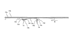
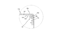
- FIG. 13 is a cross-sectional view taken along the line II of FIG. 12 for explaining the operation of the dust removing unit (No. 3). It is sectional drawing which shows a movable filter part, a dust removal part, and a drive part. It is the E section enlarged view of FIG. It is a top view which shows a frame part and a movable filter part. It is a right view of a frame part.
- FIG. 17 is a II-II sectional view and a III-III sectional view of FIG.
- FIG. 17 is a sectional view taken along line IV-IV in FIG. 16.
- FIG. 1 is a perspective view (FIG. 1 (a)) and a schematic right side view (FIG. 1 (b)) showing an electronic device casing 1 including a filter device 10.
- the electronic device housing 1 includes a filter device 10, a first electronic device housing device 2, and a second electronic device housing device 3.
- the electronic device housing 1 is used as, for example, a housing for a transmission device or a server.
- the filter device 10 is disposed between the first electronic device housing device 2 and the second electronic device housing device 3 located in the lower stage thereof. Between the filter device 10 and the first electronic device housing device 2, a plurality of cooling fans 30 that send cooling air to the first electronic device housing device 2 are arranged in parallel.
- the filter device 10 includes, for example, an inclined plate 11 that is, for example, a heat shield plate extending from the front lower end to the rear upper end as shown in FIG.
- the inclined plate 11 partitions the space on the first electronic device housing device 2 side from the space on the second electronic device housing device 3 side.
- the inclined plate 11 includes an arrangement direction (vertical direction in the present embodiment) between the first electronic device accommodation device 2 and the second electronic device accommodation device 3 and a plane orthogonal to the arrangement direction (horizontal plane in the present embodiment). ) To be inclined.
- the inclined plate 11 deflects the suction gas sucked from the front of the filter device 10 toward the first electronic device housing device 2 on one surface (upper surface) 11a. Further, the inclined plate 11 deflects the exhaust gas discharged upward from the second electronic device housing device 3 toward the rear of the filter device 10 on the other surface (bottom surface) 11b.
- the electronic device housing 1 shown in FIG. 1 includes two electronic device housing devices 2 and 3, but may include three or more arbitrary number of electronic device housing devices.
- the filter device 10 may be disposed between the electronic device housing devices.
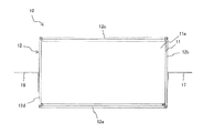
- FIGS. 2A to 2D are a perspective view, a plan view, a front view, and a right side view showing the filter device 10.
- FIG. FIG. 3 is a perspective view showing the filter device 10 with the inclined plate 11 removed.
- the filter device 10 includes the inclined plate 11, the frame portion 12 (see FIGS. 4A and 4B), the movable filter portion 13 (see FIGS. 5 to 9), and the dust removing portion 14 (see FIGS. 10A to 10E). ) And four filter driving units 15 (see FIGS. 3, 12, 14, and 15).
- the inclined plate 11 has a flat plate shape, for example, and is fixed to the lower end of the front surface portion 12a and the upper end of the back surface portion 12c of the frame portion 12 as shown in FIG. 2A.
- the inclined plate 11 partitions the space on the first electronic device housing device 2 side and the space on the second electronic device housing device 3 side, in this embodiment, the space above and below the filter device 10.
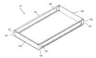
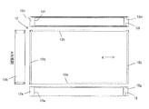
- FIG. 4A is a perspective view showing the frame portion 12, and FIG. 4B is a plan view, a front view, a perspective view, and an A arrow view showing the frame portion 12.
- FIG. The frame portion 12 includes a front surface portion 12a, a right side surface portion 12b, a back surface portion 12c, and a left side surface portion 12d, and has a rectangular frame shape in plan view. Window portions 12e and 12f are formed on the front surface portion 12a and the back surface portion 12c of the frame portion 12, respectively.
- the window portion 12e of the front surface portion 12a is an example of an “intake port” for inhaled gas to the first electronic device housing device 2 shown in FIG.
- the window portion 12 f of the back surface portion 12 c is an example of an “exhaust port” for exhaust gas from the second electronic device housing device 3.
- the upper guide convex portion 13j (not shown in FIG. 6) of the movable filter portion 13 to be described later is inserted into the front surface portion 12a, the right side surface portion 12b, the back surface portion 12c, and the left side surface portion 12d of the frame portion 12.
- Upper guide holes 12g, 12h, 12i, and 12j are formed.
- a plurality of upper guide convex portions 13j are formed, for example, at regular intervals so as to protrude outward from the upper end of the outer peripheral surface of the upper filter holding portion 13b.
- the lower guide convex portion 13k (not shown in FIG. 6) of the movable filter portion 13 shown in FIGS. 18 and 19 is inserted into the front surface portion 12a, the right side surface portion 12b, the back surface portion 12c, and the left side surface portion 12d of the frame portion 12.
- Lower guide holes 12k, 12l, 12m, and 12n are formed.
- a plurality of lower guide convex portions 13k are formed at regular intervals, for example, so as to protrude outward from the lower end of the outer peripheral surface of the lower filter holding portion 13c.
- the movable filter part 13 is supported by the frame part 12 and the four filter drive parts 15, for example.
- the movable filter portion 13 is supported by the frame portion 12 by inserting the upper guide convex portion 13j and the lower guide convex portion 13k into the upper guide holes 12g to 12j and the lower guide holes 12k to 12n of the frame portion 12, respectively. Is done.
- the movable filter portion 13 is supported by the four filter driving portions 15 as an upper meshing hole 13f and a lower meshing hole 13g described later mesh with the upper gear 15b and the lower gear 15c of the four filter driving portions 15.
- the upper guide hole 12g and the lower guide hole 12k of the front surface portion 12a are formed in parallel to each other with a window portion 12e formed in the front surface portion 12a interposed therebetween.
- the upper guide hole 12i and the lower guide hole 12m of the back surface portion 12c are formed in parallel to each other with a window portion 12f formed in the back surface portion 12c interposed therebetween.
- the length between the upper guide hole 12h and the lower guide hole 12l on the front end side of the right side surface portion 12b is between the upper guide hole 12g and the lower guide hole 12k of the front surface portion 12a.
- the length H1 is the same as the length.
- the upper guide hole 12h and the lower guide hole 12l of the right side surface portion 12b are inclined at an angle ⁇ from the horizontal so as to move away from each other from the front end side toward the rear end side.
- the length between the upper guide hole 12h and the lower guide hole 121 on the rear end side of the right side surface portion 12b is the same as the length between the upper guide hole 12i and the lower guide hole 12m of the back surface portion 12c. H2.
- the horizontal lengths of the upper guide hole 12h and the lower guide hole 12l of the right side surface portion 12b are the length L, respectively. Therefore, the length H2 is represented by “H1 + 2 ⁇ (Ltan ⁇ )”.
- the upper guide hole 12j and the lower guide hole 12n of the left side surface portion 12d are inclined at an angle ⁇ from the horizontal so as to move away from each other from the front end side toward the rear end side.
- the length between the upper guide hole 12j and the lower guide hole 12n of the left side surface portion 12d is the length H1 on the front end side and the length H2 on the rear end side, like the right side surface portion 12b.
- the movable filter portion 13 circulates so as to surround the periphery of the inclined plate 11 counterclockwise in plan view as shown in FIG. Therefore, the stretchable filter 13a (movable filter portion 13) is pulled in the height direction from the front end to the rear end between the upper guide hole 12h and the lower guide hole 12l of the right side surface portion 12b. Expand (filter 13a 'in the II-II sectional view on the left side of FIG. 18).
- the expanded filter 13a circulates in an expanded state by being pulled in the height direction even between the upper guide hole 12i and the lower guide hole 12m that are parallel to each other in the back surface portion 12c. And the degree to which the expanded filter 13a ′ is pulled in the height direction from the rear end to the front end decreases between the upper guide hole 12j and the lower guide hole 12n of the left side surface portion 12d (the filter shown in FIG. 19). 13a ′′) and returns to the original height at the front end of the left side surface portion 12d.
- the upper guide holes 12g to 12j and the lower guide holes 12k to 12n described above are “guides” of the “filter extension portion” that expands the movable filter portion 13 on the back surface thereof (a portion where dust is removed by the dust removing portion 14). Part "is an example.
- the upper guide holes 12g to 12j and the lower guide holes 12k to 12n increase or decrease the distance between each other in the circumferential direction (arrow R) of the movable filter section 13 to thereby filter the filter of the movable filter section 13. 13a is expanded.
- the distance between the upper guide holes 12g to 12j and the lower guide holes 12k to 12n is increased or decreased in the movable filter portion 13 where dust is removed by the dust removing portion 14 (for example, on the back surface portion 12c). Only the upper guide hole 12i and the lower guide hole 12m) may be provided.
- the upper guide holes 12g to 12j and the lower guide holes 12k to 12n may be provided in the movable filter 13, and the upper guide convex part 13j and the lower guide convex part 13k may be provided in the frame part 12.
- the “guide portion” is not limited to the guide hole and the guide convex portion, but may be any one that can guide the movable filter portion 13.
- the “filter extension part” may be any part that expands the movable filter part 13, it may have other structures such as one that pulls the filter 13 a and one that presses the filter 13 a.
- the right side surface portion 12b of the frame portion 12 is illustrated so as not to open to the inner peripheral surface (the inner side of the orbit), but the inner side surface is similar to the left side surface portion 12d illustrated in FIG. It is assumed that it opens to the peripheral surface.
- L-shaped fixtures 16 and 17 are fixed to the right side surface portion 12b and the left side surface portion 12d of the frame portion 12, respectively.
- the filter device 10 is attached to the left and right support columns 6 and 7 of the electronic device casing 1 by, for example, fixtures 16 and 17.
- FIG. 5 is a perspective view showing the filter 13a.
- FIG. 6 is a plan view, a front view, and a right side view showing the upper filter holding portion 13b
- FIG. 7 is a view as viewed in the direction of arrow B in FIG.
- FIG. 8 is a plan view, a front view, and a right side view showing the lower filter holding portion 13c
- FIG. 9 is a view taken in the direction of arrow C in FIG.
- the movable filter section 13 includes a stretchable filter 13a shown in FIG. 5, an upper filter holding section 13b shown in FIGS. 6 and 7, and a lower filter holding section 13c shown in FIGS.
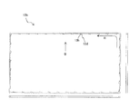
- the movable filter unit 13 circulates around the inclined plate 11 counterclockwise as shown in FIG. 11 by the filter driving unit 15 described later (circulation direction R). Since the frame portion 12 has a rectangular shape in plan view as described above, the filter 13a, the upper filter holding portion 13b, and the lower filter holding portion 13c are flexible so that they can go around the four corners of the frame portion 12. Have.
- the filter 13a is made of a stretchable material and has a strip shape.
- the filter 13a is formed in an endless loop shape, but dust can be removed if it is located in at least one of the window portions 12e and 12f. Therefore, the filter 13a may be provided with a plurality of filters having a size covering the window portions 12e and 12f in the circumferential direction.
- the upper filter holding portion 13b and the lower filter holding portion 13c have a loop shape, and hold the upper and lower ends of the filter 13a, for example, by holding them as shown in FIGS.
- the upper filter holding part 13b and the lower filter holding part 13c are provided symmetrically with the filter 13a interposed therebetween.
- the upper pressed portion 14f of the dust removing portion 14 (FIG. 3, FIG. 10A, etc.) is pressed against the lower end of the inner peripheral surface of the upper filter holding portion 13b.
- a plurality of upper protrusions 13d are arranged at equal intervals in the circumferential direction (arrow R) of the movable filter 13.
- a lower protrusion that presses the lower pressed portion 14g of the dust removing portion 14 A plurality of 13e are arranged at equal intervals in the circumferential direction (arrow R).
- the upper protruding portion 13d and the lower protruding portion 13e increase in thickness as the amount of protrusion increases from the front end to the rear end in the circumferential direction (arrow R), and the rear end surfaces are the upper filter holding portion 13b and the lower filter holding portion. It exhibits a right-angled triangular shape in plan view that is perpendicular to 13c.
- the upper protrusion 13d and the lower protrusion 13e include slits 13h, which are recesses, on the inclined surfaces on the inner peripheral side of the upper filter holder 13b and the lower filter holder 13c. 13i is formed. These slits 13h and 13i relieve bending stress applied to the upper protrusion 13d and the lower protrusion 13e when the movable filter 13 circulates around the four corners of the filter device 10. As a result, the upper protrusion 13d and the lower protrusion 13e can be easily turned and thus the movable filter part 13 can be easily turned.
- the number of the upper protrusions 13d and the lower protrusions 13e may be one each, or may be several tens as shown in FIGS. This number is appropriately determined according to the number of rotations of a motor 15a of the filter driving unit 15 described later, the dust removing capability of the dust removing unit 14, the degree of dust adhering to the filter 13a, and the like.
- upper meshing holes 13f that mesh with the upper gear 15b of the filter driving portion 15 shown in FIG. 15 are formed at equal intervals in the circumferential direction (arrow R).
- lower meshing holes 13g that mesh with the lower gear 15c of the filter driving portion 15 are formed at equal intervals in the circumferential direction (arrow R).
- 10A to 10E are a perspective view, a plan view, a front view, a left side view, and a right side view showing the dust removing unit 14, respectively.
- the dust removing unit 14 is formed, for example, by appropriately bending a thin plate processed into a predetermined shape.
- the dust removing unit 14 is provided, for example, on the inner side of the orbit of the movable filter unit 13, and ejects the dust of the filter 13 a to the outside of the orbit from the window portion 12 g of the back surface portion 12 c of the frame portion 12.
- the dust removing portion 14 includes a flapping portion 14a, a flapping portion support portion 14b, a base portion 14c, an upper fixing portion 14d and a lower fixing portion 14e, an upper pressed portion 14f, and a lower pressed portion 14g.
- the knocking portion 14 a has a long rectangular shape in the circumferential direction of the movable filter portion 13 and is provided so as to face the movable filter portion 13.
- the flapping portion support portion 14b extends from the right end of the flapping portion 14a (the right direction in the drawing of FIG. 10B) to the rear (the direction away from the movable filter portion 13; the downward direction of the drawing in FIG. 10B).
- the hitting portion support portion 14b has a rectangular shape that is shorter in the front-rear direction than the height direction, and the upper end position and the lower end position are the same as the hitting portion 14a.
- the base portion 14c is parallel to the striking portion support portion 14b across two right-angled bent portions on the rear end side of the striking portion support portion 14b, and faces the striking portion support portion 14b with a slight gap therebetween. Yes.
- the base portion 14c protrudes upward and downward from the hitting portion 14a and the hitting portion support portion 14b.
- the base 14c is formed longer in the height direction and shorter in the front-rear direction than the striking part support 14b.
- a rectangular recess 14h is formed on the movable filter portion 13 side.
- the recess 14h allows the upper protrusion 13d of the upper filter holding part 13b and the lower protrusion 13e of the lower filter holding part 13c to pass between the striking part support part 14b. Therefore, the concave portion 14h is formed longer in the height direction than the total height of the striking portion support portion 14b, the upper protruding portion 13d, and the lower protruding portion 13e.
- the upper fixing portion 14d and the lower fixing portion 14e are formed by folding the upper end and the lower end of the front end of the base portion 14c to the side opposite to the striking portion 14a.
- the dust removing portion 14 is fixed to the frame portion 12 at the upper fixing portion 14d and the lower fixing portion 14e.
- the upper pressed portion 14f and the lower pressed portion 14g are arranged such that the upper horizontal portion 14i and the lower horizontal portion 14j extending rearward from the left end of the upper end and the lower end of the hitting portion 14a, and the rear ends of these horizontal portions 14i and 14j And an upper contact portion 14k and a lower contact portion 14l.
- the depth in the front-rear direction of the upper horizontal portion 14i and the lower horizontal portion 14j is such that the right end depth D1 is larger than the left end depth D2, as shown in FIG. 10B.
- the upper protrusion 13d of the movable filter portion 13 that circulates from right to left can easily enter the upper horizontal portion 14i, and the lower protrusion 13e can enter the lower horizontal portion 14j.
- the upper projection 13d can easily press the upper contact portion 14k, and the lower projection 13e can easily press the lower contact portion 14l.
- the flapping portion 14a rotates, for example, between a position pressed and moved away and a position flapping the filter 13a, with a bent portion between the flapping portion 14a and the flapping portion support portion 14b as a rotation axis.
- the bent part between the support part 14b and the base part 14c may become a rotation axis.
- the flapping portion 14a may have a shape other than a flat shape, such as a curved surface that curves away from the movable filter portion 13 from the right end to the left end. .
- the dust removing unit 14 removes dust by hitting the filter 13a with the flapping unit 14a, but it may be removed by other methods.
- the dust removing unit 14 includes a discharge mechanism that removes dust by discharging air, a suction mechanism that removes dust by sucking air, a scraping mechanism that scrapes dust with a brush, and a scraper that scrapes dust with a brush. It is good also as what has other mechanisms, such as a mechanism.
- Each of the four filter drive units 15 includes a motor 15a, an upper gear 15b, a lower gear 15c, and a drive shaft 15d.
- the motor 15a drives the drive shaft 15d counterclockwise.
- the upper gear 15b and the lower gear 15c fixed to the drive shaft 15d rotate counterclockwise together with the drive shaft 15d.
- the movable filter unit 13 rotates around the inclined plate 11 counterclockwise by driving the motor 15a.
- the filter drive unit 15 may periodically circulate without moving the movable filter unit 13.
- the motor 15a of the filter drive unit 15 drives the drive shaft 15d counterclockwise in plan view. Since the upper gear 15b and the lower gear 15c are fixed to the drive shaft 15d, they rotate counterclockwise together with the drive shaft 15d.
- the movable filter unit 13 is meshed with the upper mesh hole 13f of the upper filter holding unit 13b in the upper gear 15b and the lower mesh hole 13g of the lower filter holding unit 13c in the lower gear 15c as shown in FIG. As shown, it circulates in the counterclockwise direction (arrow R).
- the movable filter holding portion 13 is guided by the upper guide holes 12g to 12j and the lower guide holes 12k to 12n into which the upper guide convex portions 13j and the lower guide convex portions 13k shown in FIGS. 18 and 19 are inserted. . As a result, the movable filter portion 13 circulates along the frame portion 12 in the circulation direction (arrow R).
- the upper guide hole 12h and the lower guide hole 12l of the right side surface portion 12b of the frame portion 12 are respectively horizontal so as to move away from the front end side toward the rear end side, as shown in FIG. From the angle ⁇ .
- the distance between the upper guide hole 12h and the lower guide hole 121 is a length H1 at the front end of the right side surface portion 12b and a length H2 at the rear end. Since the horizontal length of the upper guide hole 12h and the lower guide hole 12l is the length L, the length H2 is represented by “H1 + 2 ⁇ (Ltan ⁇ )”.
- the filter 13a and the movable filter portion 13 are expanded (the filter 13a ′ in the II-II cross-sectional view on the left side of FIG. 18).
- the movable filter portion 13 circulates while being stretched and pulled in the height direction even between the upper guide hole 12i and the lower guide hole 12m which are parallel to each other on the back surface portion 12c.
- the movable filter portion 13 is less pulled in the height direction from the rear end to the front end between the upper guide hole 12j and the lower guide hole 12n of the left side surface portion 12d (filter 13a shown in FIG. 19). ⁇ ⁇ ).
- the movable filter part 13 returns to the original height (height in the front surface part 12a) in the front end of the left side surface part 12d.
- the protrusions 13d and 13e of the upper filter holding portion 13b and the lower filter holding portion 13c are the upper pressed portion 14f and the lower pressed portion of the dust removing portion 14 during rotation. 14g is pressed (see FIGS. 13A and 13B).
- the upper protruding portion 13d and the lower protruding portion 13e are configured so that the hitting portion 14a is replaced with the movable filter portion 1.
- the expanded movable filter portion 13 (filter 13a) is applied by the knocking portion 14a.
- the filter device 10 includes the inclined plate 11 that partitions the space on the first electronic device housing device 2 side and the space on the second electronic device housing device 3 side, and the inclined plate 11. And a movable filter section 13 that circulates around the periphery. Therefore, the movable filter unit 13 can absorb dust and the like contained in the gas sucked into the first electronic device housing device 2 with the entire movable filter unit 13. Therefore, according to the present embodiment, it is possible to reduce the maintenance burden on the filter.
- the movable filter unit 13 since the movable filter unit 13 circulates around the inclined plate 11, it can absorb dust contained in the gas sucked into the first electronic device housing device 2 and the second electronic device housing device 3. Dust can be discharged with the exhaust gas from.
- the filter device 10 includes a dust removing unit 14 that removes dust attached to the movable filter unit 13. Therefore, the maintenance burden of the filter can be further reduced.
- the movable filter unit 13 is connected to the first electronic device housing device 2 from the suction port of the suction gas (the window portion 12e of the front surface portion 12a of the frame portion 12) and the second electronic device housing device 3. Circulates around the inclined plate 11 over the exhaust gas discharge port (the window portion 12f of the back surface portion 12c). And the dust removal part 14 removes dust in the said discharge port (window part 12f). Therefore, it is possible to suppress the removed dust from adhering to the electronic device 20.
- the filter expansion part moves the movable filter part 13 (filter 13a) to the dust removing part 14. Expansion is performed at a portion where dust is removed (for example, the back surface portion 12c of the frame portion 12). Therefore, dust can be more reliably removed by the dust removing unit 14.
- the distance between the upper guide holes 12g to 12j and the lower guide holes 12k to 12n of the frame portion 12 increases or decreases in the circumferential direction (arrow R) of the movable filter portion 13. Therefore, the movable filter unit 13 (filter 13a) can be expanded with a simple configuration.
- the upper protrusion 13d and the lower protrusion 13e of the movable filter part 13 move the striking part 14a away from the movable filter part 13 during rotation, and the receding part 14a causes the movable filter part 13 (filter 13a) is applied. Therefore, dust can be removed with a simple configuration.
- the movable filter unit 13 includes a filter 13a, and an upper filter holding unit 13b and a lower filter holding unit 13c that hold the filter 13a.
- the upper protruding portion 13d and the lower protruding portion 13e are provided on the upper filter holding portion 13b and the lower filter holding portion 13c. Therefore, dust can be removed with a simpler configuration.
- the upper protrusion 13d and the lower protrusion 13e are formed with recesses (slits 13h, 13i) that relieve bending stress applied when the movable filter portion 13 circulates. Therefore, it is possible to prevent the movable filter portion 13 from being hindered from smooth circulation by the upper protrusion portion 13d and the lower protrusion portion 13e.
Landscapes
- Engineering & Computer Science (AREA)
- Microelectronics & Electronic Packaging (AREA)
- Physics & Mathematics (AREA)
- Thermal Sciences (AREA)
- Chemical & Material Sciences (AREA)
- Chemical Kinetics & Catalysis (AREA)
- Aviation & Aerospace Engineering (AREA)
- Cooling Or The Like Of Electrical Apparatus (AREA)
Abstract
フィルタ装置は、傾斜板と、可動フィルタ部とを備える。傾斜板は、電子装置を収容する第1の電子装置収容装置と第2の電子装置収容装置との間に配置され、上記第1の電子装置収容装置側の空間と上記第2の電子装置収容装置側の空間とを仕切る。可動フィルタ部は、上記傾斜板の周囲を取り囲むように周回する。
Description
本明細書で議論される実施態様は、可動フィルタ部を備えるフィルタ装置、並びに、このフィルタ装置及び電子装置を備える電子装置用筐体に関する。
近年、電子装置は、更なる高密度実装を実現するために装置内部を冷却する必要があり、冷却ファンによる強制空冷が一般化してきている。
電子装置を収容する電子装置用筐体のように、外装面に設けられた吸入口から冷却ファンにより冷却空気を取り入れる構造においては、吸入口に取り付けたフィルタを定期的に又は装置警報があった際に速やかに交換する必要がある。
電子装置を収容する電子装置用筐体のように、外装面に設けられた吸入口から冷却ファンにより冷却空気を取り入れる構造においては、吸入口に取り付けたフィルタを定期的に又は装置警報があった際に速やかに交換する必要がある。
装置警報としては、例えば、フィルタに塵埃等が溜まり吸入口からの吸入風量が低下したことを通知する装置警報や、装置内部温度が規定値を超えたことを通知する装置警報である。
ところで、フィルタを備える機器の例としては、ファンを備える凝縮器の全周を取り囲むようにエンドレス状の帯状フィルタが配置され、このフィルタの途中がフィルタ回転移動用の駆動ローラに掛合した冷凍装置が知られている。
また、粉体物回収装置として、ケーシング内に、ケーシングの空気入口を遮って回走するエンドレス濾材が設けられ、かつ、濾材に付着した粉粒体を濾材から離脱せしめる粉粒体除去装置が設けられた粉体物回収装置が知られている。
ところで、上述の電子装置用筐体におけるフィルタの交換は、フィルタ自体の費用が発生するだけでなく、電子装置が設置される場所が無人である場合にはフィルタ交換の度に人を派遣する必要があるなど、フィルタのメンテナンス負担が生じる。
本発明の目的は、フィルタのメンテナンス負担を軽減することができるフィルタ装置及び電子装置用筐体を提供することである。
本明細書で開示するフィルタ装置は、傾斜板と、可動フィルタ部とを備える。傾斜板は、電子装置を収容する第1の電子装置収容装置と第2の電子装置収容装置との間に配置され、上記第1の電子装置収容装置側の空間と上記第2の電子装置収容装置側の空間とを仕切る。可動フィルタ部は、上記傾斜板の周囲を取り囲むように周回する。
本明細書で開示する電子装置用筐体は、上記フィルタ装置と、上記第1の電子装置収容装置及び上記第2の電子装置収容装置と、を備える。
本明細書で開示するフィルタ装置及び電子装置用筐体によれば、フィルタのメンテナンス負担を軽減することができる。
以下、実施の形態に係るフィルタ装置及び電子装置用筐体について、図面を参照しながら説明する。
図1は、フィルタ装置10を備える電子装置用筐体1を示す斜視図(図1(a))及び概略右側面図(図1(b))である。
図1は、フィルタ装置10を備える電子装置用筐体1を示す斜視図(図1(a))及び概略右側面図(図1(b))である。
図1に示す電子装置用筐体1は、フィルタ装置10と、第1の電子装置収容装置2と、第2の電子装置収容装置3とを備える。電子装置用筐体1は、例えば、伝送装置やサーバ用の筐体として用いられる。
第1の電子装置収容装置2及び第2の電子装置収容装置3には、任意数の電子装置20が、対応する支持部4,5により支持された状態で収容される。
フィルタ装置10は、第1の電子装置収容装置2と、その下段に位置する第2の電子装置収容装置3との間に配置されている。フィルタ装置10と第1の電子装置収容装置2との間には、第1の電子装置収容装置2に冷却用空気を送る複数の冷却ファン30が並列に配置されている。
フィルタ装置10は、第1の電子装置収容装置2と、その下段に位置する第2の電子装置収容装置3との間に配置されている。フィルタ装置10と第1の電子装置収容装置2との間には、第1の電子装置収容装置2に冷却用空気を送る複数の冷却ファン30が並列に配置されている。
フィルタ装置10について詳しくは後述するが、フィルタ装置10は、例えば図1(b)に示すように前方下端から後方上端に亘って延びる例えば熱遮蔽板である傾斜板11を含む。
この傾斜板11は、第1の電子装置収容装置2側の空間と第2の電子装置収容装置3側の空間とを仕切っている。傾斜板11は、第1の電子装置収容装置2と第2の電子装置収容装置3との配列方向(本実施の形態では鉛直方向)及びこの配列方向に直交する平面(本実施の形態では水平面)に対し傾斜して設けられている。
傾斜板11は、一方の面(上面)11aで、フィルタ装置10の前方から吸入される吸入気体を第1の電子装置収容装置2へ向けて上方に偏向させる。また、傾斜板11は、他方の面(底面)11bで、第2の電子装置収容装置3から上方に排出される排出気体をフィルタ装置10の後方へ向けて偏向させる。
なお、図1に示す電子装置用筐体1は、2つの電子装置収容装置2,3を備えるが、3つ以上の任意数の電子装置収容装置を備えるようにしてもよく、その場合も、各電子装置収容装置の間にフィルタ装置10を配置するとよい。
図2A~図2Dは、フィルタ装置10を示す斜視図、平面図、正面図及び右側面図である。
図3は、傾斜板11を取り除いた状態のフィルタ装置10を示す斜視図である。
フィルタ装置10は、上述の傾斜板11と、枠部12(図4A及び図4B参照)と、可動フィルタ部13(図5~図9参照)と、塵埃除去部14(図10A~図10E参照)と、4つのフィルタ駆動部15(図3、図12、図14及び図15参照)とを備える。
図3は、傾斜板11を取り除いた状態のフィルタ装置10を示す斜視図である。
フィルタ装置10は、上述の傾斜板11と、枠部12(図4A及び図4B参照)と、可動フィルタ部13(図5~図9参照)と、塵埃除去部14(図10A~図10E参照)と、4つのフィルタ駆動部15(図3、図12、図14及び図15参照)とを備える。
傾斜板11は、例えば平板状を呈し、図2Aに示すように枠部12の前面部12aの下端と背面部12cの上端とに固定されている。傾斜板11は、第1の電子装置収容装置2側の空間及び第2の電子装置収容装置3側の空間、本実施の形態では、フィルタ装置10の上下の空間を仕切る。
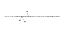
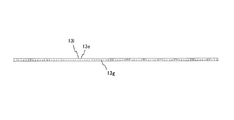
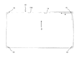
図4Aは枠部12を示す斜視図であり、図4Bは枠部12を示す平面図、正面図、斜視図及びA矢視図である。
枠部12は、前面部12aと、右側面部12bと、背面部12cと、左側面部12dとを含み、平面視において矩形枠状を呈する。枠部12の前面部12a及び背面部12cには、窓部12e,12fが形成されている。
枠部12は、前面部12aと、右側面部12bと、背面部12cと、左側面部12dとを含み、平面視において矩形枠状を呈する。枠部12の前面部12a及び背面部12cには、窓部12e,12fが形成されている。
なお、前面部12aの窓部12eは、図1に示す第1の電子装置収容装置2への吸入気体の「吸入口」の一例である。背面部12cの窓部12fは、第2の電子装置収容装置3からの排出気体の「排出口」の一例である。
枠部12の前面部12a、右側面部12b、背面部12c及び左側面部12dには、後述する可動フィルタ部13の図18及び図19に示す上側ガイド用凸部13j(図6では省略)を挿入される上側ガイド孔12g,12h,12i,12jが形成されている。
図18及び図19に示すように、上側ガイド用凸部13jは、上側フィルタ保持部13bの外周面の上端から外側に突出するように例えば一定間隔で複数個形成されている。
枠部12の前面部12a、右側面部12b、背面部12c及び左側面部12dには、可動フィルタ部13の図18及び図19に示す下側ガイド用凸部13k(図6では省略)を挿入される下側ガイド孔12k,12l,12m,12nが形成されている。
枠部12の前面部12a、右側面部12b、背面部12c及び左側面部12dには、可動フィルタ部13の図18及び図19に示す下側ガイド用凸部13k(図6では省略)を挿入される下側ガイド孔12k,12l,12m,12nが形成されている。
図18及び図19に示すように、下側ガイド用凸部13kは、下側フィルタ保持部13cの外周面の下端から外側に突出するように例えば一定間隔で複数個形成されている。
可動フィルタ部13は、例えば、枠部12及び4つのフィルタ駆動部15によって支持される。可動フィルタ部13は、上側ガイド用凸部13j及び下側ガイド用凸部13kが枠部12の上側ガイド孔12g~12j及び下側ガイド孔12k~12nに挿入されることで枠部12に支持される。また、可動フィルタ部13は、後述する上側噛合孔13f及び下側噛合孔13gが4つのフィルタ駆動部15の上側歯車15b及び下側歯車15cに噛合することで4つのフィルタ駆動部15に支持される。
可動フィルタ部13は、例えば、枠部12及び4つのフィルタ駆動部15によって支持される。可動フィルタ部13は、上側ガイド用凸部13j及び下側ガイド用凸部13kが枠部12の上側ガイド孔12g~12j及び下側ガイド孔12k~12nに挿入されることで枠部12に支持される。また、可動フィルタ部13は、後述する上側噛合孔13f及び下側噛合孔13gが4つのフィルタ駆動部15の上側歯車15b及び下側歯車15cに噛合することで4つのフィルタ駆動部15に支持される。
前面部12aの上側ガイド孔12gと下側ガイド孔12kとは、前面部12aに形成された窓部12eを挟んで互いに平行に形成されている。同様に、背面部12cの上側ガイド孔12iと下側ガイド孔12mとは、背面部12cに形成された窓部12fを挟んで互いに平行に形成されている。
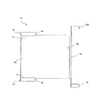
図17に示すように、右側面部12bの前端側における上側ガイド孔12hと下側ガイド孔12lとの間の長さは、前面部12aの上側ガイド孔12gと下側ガイド孔12kとの間の長さと同一の長さH1である。
右側面部12bの上側ガイド孔12hと下側ガイド孔12lとは、前端側から後端側に向かって、互いに遠ざかるように、それぞれ水平から角度θ傾いている。右側面部12bの後端側における上側ガイド孔12hと下側ガイド孔12lとの間の長さは、背面部12cの上側ガイド孔12iと下側ガイド孔12mとの間の長さと同一の長さのH2である。
ここで、右側面部12bの上側ガイド孔12h及び下側ガイド孔12lの水平方向の長さは、それぞれ長さLである。そのため、長さH2は、「H1+2×(Ltanθ)」で表される。
図示はしないが、左側面部12dの上側ガイド孔12jと下側ガイド孔12nとは、前端側から後端側に向かって、互いに遠ざかるように、それぞれ水平から角度θ傾いている。左側面部12dの上側ガイド孔12jと下側ガイド孔12nとの間の長さは、右側面部12bと同様に、前端側が長さH1で後端側が長さH2である。
詳しくは後述するが、可動フィルタ部13は、図3に示すように平面視反時計回りに傾斜板11の周囲を取り囲むように周回する。そのため、右側面部12bの上側ガイド孔12hと下側ガイド孔12lとの間で、伸縮性を有するフィルタ13a(可動フィルタ部13)は、前端から後端にいくほど高さ方向に引っ張られることで拡張する(図18の紙面左側のII-II断面図のフィルタ13a´)。
なお、拡張したフィルタ13a´は、背面部12cの互いに平行な上側ガイド孔12iと下側ガイド孔12mとの間でも高さ方向に引っ張られ拡張した状態のまま周回する。そして、拡張したフィルタ13a´は、左側面部12dの上側ガイド孔12jと下側ガイド孔12nとの間で、後端から前端にいくほど高さ方向に引っ張られる度合いが弱まり(図19に示すフィルタ13a´´)、左側面部12dの前端において、元の高さに戻る。
以上の上側ガイド孔12g~12j及び下側ガイド孔12k~12nは、可動フィルタ部13を、その背面(塵埃除去部14により塵埃が除去される部分)において拡張させる「フィルタ拡張部」の「ガイド部」の一例である。
以上のように、上側ガイド孔12g~12jと下側ガイド孔12k~12nとは、可動フィルタ部13の周回方向(矢印R)に亘って互いの間隔を増減させることで可動フィルタ部13のフィルタ13aを拡張させる。
なお、上側ガイド孔12g~12jと下側ガイド孔12k~12nとの間隔を増減させるのは、可動フィルタ部13のうち、塵埃除去部14により塵埃が除去される部分(例えば、背面部12cの上側ガイド孔12i及び下側ガイド孔12m)のみとしてもよい。
また、上側ガイド孔12g~12j及び下側ガイド孔12k~12nを可動フィルタ13に設け、上側ガイド用凸部13j及び下側ガイド用凸部13kを枠部12に設けてもよい。また、「ガイド部」としては、ガイド孔及びガイド用凸部によるものでなくとも、可動フィルタ部13をガイドしうるものであればよい。また、「フィルタ拡張部」としては、可動フィルタ部13を拡張させるものであればよいため、フィルタ13aを引張るものや、フィルタ13aを押付けるものなど、その他の構造としてもよい。
なお、図3及び図4Aでは、枠部12の右側面部12bが内周面(周回軌道の内側)に開口していないように図示しているが、図19に示す左側面部12dと同様に内周面に開口しているものとする。
なお、図3及び図4Aでは、枠部12の右側面部12bが内周面(周回軌道の内側)に開口していないように図示しているが、図19に示す左側面部12dと同様に内周面に開口しているものとする。
枠部12の右側面部12b及び左側面部12dには、それぞれL字状の取付具16,17が固定されている。フィルタ装置10は、例えば、取付具16,17によって電子装置用筐体1の左右の支柱6,7に対し取付けられる。
図5は、フィルタ13aを示す斜視図である。
図6は上側フィルタ保持部13bを示す平面図、正面図及び右側面図であり、図7は図6のB矢視図である。
図6は上側フィルタ保持部13bを示す平面図、正面図及び右側面図であり、図7は図6のB矢視図である。
図8は下側フィルタ保持部13cを示す平面図、正面図及び右側面図であり、図9は図8のC矢視図である。
可動フィルタ部13は、図5に示す伸縮性を有するフィルタ13aと、図6及び図7に示す上側フィルタ保持部13bと、図8及び図9に示す下側フィルタ保持部13cとを含む。
可動フィルタ部13は、図5に示す伸縮性を有するフィルタ13aと、図6及び図7に示す上側フィルタ保持部13bと、図8及び図9に示す下側フィルタ保持部13cとを含む。
可動フィルタ部13は、後述するフィルタ駆動部15によって図11に示すように反時計回りに、傾斜板11の周囲を取り囲むように周回する(周回方向R)。枠部12は上述のように平面視において矩形状を呈するため、フィルタ13a、上側フィルタ保持部13b及び下側フィルタ保持部13cは、枠部12の四つ角部分を周回可能なように可撓性を有する。
フィルタ13aは、伸縮性を有する材料からなり、帯状を呈する。フィルタ13aは、無端ループ状に形成されているが、少なくとも一方の窓部12e,12fに位置すれば塵埃を除去できる。そのため、フィルタ13aは、窓部12e,12fを覆う大きさのフィルタが周回方向に複数個設けられているものでもよい。
上側フィルタ保持部13b及び下側フィルタ保持部13cは、ループ状を呈し、図18及び図19に示すように、フィルタ13aの上端及び下端を例えば挟持することで保持する。上側フィルタ保持部13bと下側フィルタ保持部13cとは、フィルタ13aを挟んで対称的に設けられている。
上側フィルタ保持部13bの内周面下端には、図6、図7、図18及び図19に示すように、塵埃除去部14(図3、図10A等)の上側被押圧部14fを押圧する上側突起部13dが可動フィルタ13の周回方向(矢印R)に等間隔に複数個配置されている。
同様に、下側フィルタ保持部13cの内周面上端には、図8、図9及び18及び図19に示すように、塵埃除去部14の下側被押圧部14gを押圧する下側突起部13eが周回方向(矢印R)に等間隔に複数個配置されている。
例えば、上側突起部13d及び下側突起部13eは、周回方向(矢印R)の前端から後端にいくほど突出量である厚みが増し、後端面が上側フィルタ保持部13b及び下側フィルタ保持部13cと直角をなす平面視直角三角形状を呈する。
上側突起部13d及び下側突起部13eには、図13A~図13Cにも示すように、上側フィルタ保持部13bおよび下側フィルタ保持部13cの内周側の傾斜面に凹部であるスリット13h,13iが形成されている。これらスリット13h,13iは、可動フィルタ部13がフィルタ装置10の四つ角を周回する際に、上側突起部13d及び下側突起部13eに加わる曲げ応力を緩和する。これによって、上側突起部13d及び下側突起部13eの周回ひいては可動フィルタ部13の周回が容易になる。
なお、上側突起部13d及び下側突起部13eの数は、それぞれ1個ずつとしてもよく、また、図6~図9に示すように数十個ずつとしてもよい。この数は、後述するフィルタ駆動部15のモータ15aの回転数や、塵埃除去部14の塵埃除去能力や、フィルタ13aへの塵埃の付着の度合いなどに応じて適宜決定される。
上側フィルタ保持部13bの内周面上端には、図15に示すフィルタ駆動部15の上側歯車15bに噛合する上側噛合孔13fが周回方向(矢印R)に等間隔に形成されている。下側フィルタ保持部13cの内周面下端には、フィルタ駆動部15の下側歯車15cに噛合する下側噛合孔13gが周回方向(矢印R)に等間隔に形成されている。
図10A~図10Eは、塵埃除去部14を示す斜視図、平面図、正面図、左側面図及び右側面図である。
塵埃除去部14は、例えば、所定の形状に加工された薄板を適宜屈曲させることで形成される。塵埃除去部14は、例えば、可動フィルタ部13の周回軌道の内側に設けられ、フィルタ13aの塵埃を、枠部12の背面部12cの窓部12gから上記周回軌道の外側にはたき出す。
塵埃除去部14は、例えば、所定の形状に加工された薄板を適宜屈曲させることで形成される。塵埃除去部14は、例えば、可動フィルタ部13の周回軌道の内側に設けられ、フィルタ13aの塵埃を、枠部12の背面部12cの窓部12gから上記周回軌道の外側にはたき出す。
塵埃除去部14は、はたき部14aと、はたき部支持部14bと、基部14cと、上側固定部14d及び下側固定部14eと、上側被押圧部14f及び下側被押圧部14gとを含む。
はたき部14aは、可動フィルタ部13の周回方向に長い矩形状を呈し、可動フィルタ部13と対向するように設けられている。
はたき部支持部14bは、はたき部14aの右端(図10Bの紙面右方向)から後方(可動フィルタ部13と遠ざかる方向。図10Bの紙面下方向)に延びる。はたき部支持部14bは、高さ方向よりも前後方向に短い矩形状を呈し、はたき部14aと上端位置及び下端位置が同一である。
はたき部支持部14bは、はたき部14aの右端(図10Bの紙面右方向)から後方(可動フィルタ部13と遠ざかる方向。図10Bの紙面下方向)に延びる。はたき部支持部14bは、高さ方向よりも前後方向に短い矩形状を呈し、はたき部14aと上端位置及び下端位置が同一である。
基部14cは、はたき部支持部14bの後端側の2つの直角の屈曲部分を挟んではたき部支持部14bと平行となっており、はたき部支持部14bとわずかな隙間を隔てて対向している。基部14cは、はたき部14a及びはたき部支持部14bよりも上方及び下方に突出している。
基部14cは、はたき部支持部14bよりも高さ方向に長く前後方向に短く形成されている。基部14cには、可動フィルタ部13側に矩形状の凹部14hが形成されている。この凹部14hは、はたき部支持部14bとの間に、上側フィルタ保持部13bの上側突起部13d、及び、下側フィルタ保持部13cの下側突起部13eを通過させる。そのため、凹部14hは、はたき部支持部14b、上側突起部13d及び下側突起部13eの合計の高さよりも高さ方向に長く形成されている。
上側固定部14d及び下側固定部14eは、基部14cの前端の上端及び下端を、はたき部14aと反対側に折り返されてなる。塵埃除去部14は、上側固定部14d及び下側固定部14eにおいて、枠部12に対して固定されている。
上側被押圧部14f及び下側被押圧部14gは、はたき部14aの上端及び下端の左端から後方に延びる上側水平部14i及び下側水平部14jと、これら水平部14i,14jの後端を上方に屈曲させてなる上側当接部14k及び下側当接部14lとを含む。
上側水平部14i及び下側水平部14jの前後方向の奥行は、図10Bに示すように右端の奥行D1が左端の奥行D2よりも大きくなっている。これにより、右方から左方に周回する可動フィルタ部13の上側突起部13dが上側水平部14iの上方に、下側突起部13eが下側水平部14jの下方に、それぞれ進入しやすくなる。更には、上側突起部13dが上側当接部14kを、下側突起部13eが下側当接部14lを、それぞれ押圧しやすくなる。
上側当接部14k及び下側当接部14lが上側突起部13d及び下側突起部13eに押圧されると、はたき部14aは、可動フィルタ部13から後方に遠ざけられ、その反動によって、可動フィルタ部13のフィルタ13aをはたく。
はたき部14aは、例えば、はたき部14aとはたき部支持部14bとの間の屈曲部分を回動軸として、押圧され遠ざけられた位置とフィルタ13aをはたく位置とに回動するが、はたき部支持部14bと基部14cとの間の屈曲部分が回動軸となることもある。
なお、はたき部14aは、フィルタ13aをはたく機能を有するものであれば、右端から左端にいくほど可動フィルタ部13から遠ざかるように湾曲する曲面状など、平面状以外の形状であってもよい。
塵埃除去部14は、本実施の形態では、はたき部14aによってフィルタ13aをはたくことにより塵埃を除去するが、その他の手法により塵埃を除去するようにしてもよい。例えば、塵埃除去部14は、エアの吐出により塵埃を除去する吐出機構、エアの吸引により塵埃を除去する吸引機構、ブラシ等で塵埃を擦り出す擦り出し機構、ブラシ等で塵埃を擦り取る擦り取り機構等の他の機構を有するものとしてもよい。
図3、図12、図14及び図15に示すフィルタ駆動部15は、枠部12の四つ角のそれぞれに配置されている。4つのフィルタ駆動部15は、それぞれ、モータ15aと、上側歯車15bと、下側歯車15cと、駆動軸15dと、を含む。
モータ15aは、反時計回りに駆動軸15dを駆動させる。この駆動軸15dに固定されている上側歯車15b及び下側歯車15cは、駆動軸15dと共に反時計回りに回転する。
上述のように上側歯車15b及び下側歯車15cには可動フィルタ部13の上側噛合孔13f及び下側噛合孔13gが噛合する。そのため、可動フィルタ部13は、モータ15aの駆動によって反時計回りに、傾斜板11の周囲を取り囲むように周回する。
枠部12と、上側歯車15b及び下側歯車15cとの干渉を回避するために、枠部12の前面部12a、右側面部12b、背面部12c及び左側面部14dには、切り欠きが形成されている。フィルタ駆動部15は、常に可動フィルタ部13を周回させなくとも、例えば定期的に周回させてもよい。
以下、フィルタ装置10の動作について上述の説明と重複する点については適宜省略しながら説明する。
まず、図14、図15等に示すように、フィルタ駆動部15のモータ15aは、平面視反時計回りに駆動軸15dを駆動させる。上側歯車15b及び下側歯車15cは、駆動軸15dに固定されているため、駆動軸15dと共に反時計回りに回転する。
まず、図14、図15等に示すように、フィルタ駆動部15のモータ15aは、平面視反時計回りに駆動軸15dを駆動させる。上側歯車15b及び下側歯車15cは、駆動軸15dに固定されているため、駆動軸15dと共に反時計回りに回転する。
可動フィルタ部13は、上側フィルタ保持部13bの上側噛合孔13fが上側歯車15bに、下側フィルタ保持部13cの下側噛合孔13gが下側歯車15cに、それぞれ噛合することで、図11に示すように反時計回りである周回方向(矢印R)に周回する。
可動フィルタ保持部13は、図18及び図19に示す上側ガイド用凸部13j及び下側ガイド用凸部13kが挿入される上側ガイド孔12g~12j及び下側ガイド孔12k~12nによりガイドされる。これにより、可動フィルタ部13は、枠部12に沿って上記周回方向(矢印R)に周回する。
なお、上述のように、枠部12の右側面部12bの上側ガイド孔12h及び下側ガイド孔12lは、図17に示すように、前端側から後端側に向かって互いに遠ざかるように、それぞれ水平から角度θ傾いている。
上側ガイド孔12hと下側ガイド孔12lとの間隔は、右側面部12bの前端において長さH1であり、後端において長さH2である。上側ガイド孔12h及び下側ガイド孔12lの水平方向の長さが長さLであるため、長さH2は、「H1+2×(Ltanθ)」で表される。
このように、フィルタ13aは、右側面部12bの前端側から後端側にいくほど高さ方向に引っ張られる度合いが強まり、後端では高さ方向に長さ「H2-H1」(=2×(Ltanθ))引っ張られる。この引っ張りによって、フィルタ13aひいては可動フィルタ部13が拡張する(図18の紙面左側のII-II断面図のフィルタ13a´)。
上述のように、可動フィルタ部13は、背面部12cの互いに平行な上側ガイド孔12iと下側ガイド孔12mとの間でも高さ方向に引っ張られ拡張した状態のまま周回する。そして、可動フィルタ部13は、左側面部12dの上側ガイド孔12jと下側ガイド孔12nとの間で、後端から前端にいくほど高さ方向に引っ張られる度合いが弱まる(図19に示すフィルタ13a´´)。これにより、可動フィルタ部13は、左側面部12dの前端において、元の高さ(前面部12aにおける高さ)に戻る。
フィルタ13aが拡張した状態の背面部12bにおいて、上側フィルタ保持部13b及び下側フィルタ保持部13cの突起部13d,13eは、周回時に塵埃除去部14の上側被押圧部14f及び下側被押圧部14gを押圧する(図13A及び図13B参照)。これにより、上側突起部13d及び下側突起部13eは、はたき部14aを可動フィルタ部1
3から遠ざけその反動で図13Cに示すようにはたき部14aにより、拡張した可動フィルタ部13(フィルタ13a)をはたかせる。
3から遠ざけその反動で図13Cに示すようにはたき部14aにより、拡張した可動フィルタ部13(フィルタ13a)をはたかせる。
以上説明した本実施の形態では、フィルタ装置10は、第1の電子装置収容装置2側の空間と第2の電子装置収容装置3側の空間とを仕切る傾斜板11と、この傾斜板11の周囲を周回する可動フィルタ部13と、を備える。そのため、可動フィルタ部13は、第1の電子装置収容装置2への吸入気体に含まれる塵埃等を可動フィルタ部13の全体で吸収することができる。よって、本実施の形態によれば、フィルタのメンテナンス負担を軽減することができる。
更には、可動フィルタ部13が傾斜板11の周囲を周回するため、第1の電子装置収容装置2への吸入気体に含まれる塵埃を吸収することができると共に、第2の電子装置収容装置3からの排出気体で塵埃を排出することができる。
本実施の形態では、フィルタ装置10は、可動フィルタ部13に付着した塵埃を除去する塵埃除去部14を備える。そのため、フィルタのメンテナンス負担をより一層軽減することができる。
本実施の形態では、可動フィルタ部13は、第1の電子装置収容装置2への吸入気体の吸入口(枠部12の前面部12aの窓部12e)と第2の電子装置収容装置3からの排出気体の排出口(背面部12cの窓部12f)とに亘って傾斜板11の周囲を周回する。そして、塵埃除去部14は、上記排出口(窓部12f)において塵埃を除去する。そのため、除去した塵埃が電子装置20に付着するのを抑えることができる。
また、本実施の形態では、フィルタ拡張部(例えば、枠部12の上側ガイド孔12g~12j及び下側ガイド孔12k~12n)は、可動フィルタ部13(フィルタ13a)を、塵埃除去部14により塵埃が除去される部分(例えば枠部12の背面部12c)において拡張させる。そのため、塵埃除去部14によってより確実に塵埃を除去することができる。
また、本実施の形態では、枠部12の上側ガイド孔12g~12j及び下側ガイド孔12k~12nは、可動フィルタ部13の周回方向(矢印R)に亘って互いの間隔が増減する。そのため、簡素な構成で可動フィルタ部13(フィルタ13a)を拡張させることができる。
また、本実施の形態では、可動フィルタ部13の上側突起部13d及び下側突起部13eは、周回時にはたき部14aを可動フィルタ部13から遠ざけその反動ではたき部14aにより可動フィルタ部13(フィルタ13a)をはたかせる。そのため、簡素な構成で塵埃を除去することができる。
また、本実施の形態では、可動フィルタ部13は、フィルタ13aと、このフィルタ13aを保持する上側フィルタ保持部13b及び下側フィルタ保持部13cとを含む。上側突起部13d及び下側突起部13eは、上側フィルタ保持部13b及び下側フィルタ保持部13cに設けられている。そのため、より簡素な構成で塵埃を除去することができる。
また、本実施の形態では、上側突起部13d及び下側突起部13eには、可動フィルタ部13の周回時に加わる曲げ応力を緩和する凹部(スリット13h,13i)が形成されている。そのため、可動フィルタ部13が上側突起部13d及び下側突起部13eによってスムーズな周回を妨げられるのを防ぐことができる。
1 電子装置用筐体
2 第1の電子装置収容装置
3 第2の電子装置収容装置
4,5 支持部
6,7 支柱
10 フィルタ装置
11 傾斜板
11a 上面
11b 底面
12 枠部
12a 前面部
12b 右側面部
12c 背面部
12d 左側面部
12e,12f 窓部
12g,12h,12i,12j 上側ガイド孔
12k,12l,12m,12n 下側ガイド孔
13 可動フィルタ部
13a フィルタ
13b 上側フィルタ保持部
13c 下側フィルタ保持部
13d 上側突起部
13e 下側突起部
13f 上側噛合孔
13g 下側噛合孔
13h,13i スリット
13j 上側ガイド用凸部
13k 下側ガイド用凸部
14 塵埃除去部
14a はたき部
14b はたき部支持部
14c 基部
14d 上側固定部
14e 下側固定部
14f 上側被押圧部
14g 下側被押圧部
14h 凹部
14i 上側水平部
14j 下側水平部
14k 上側当接部
14l 下側当接部
15 フィルタ駆動部
15a モータ
15b 上側歯車
15c 下側歯車
15d 駆動軸
16,17 取付具
20 電子装置
30 冷却ファン
2 第1の電子装置収容装置
3 第2の電子装置収容装置
4,5 支持部
6,7 支柱
10 フィルタ装置
11 傾斜板
11a 上面
11b 底面
12 枠部
12a 前面部
12b 右側面部
12c 背面部
12d 左側面部
12e,12f 窓部
12g,12h,12i,12j 上側ガイド孔
12k,12l,12m,12n 下側ガイド孔
13 可動フィルタ部
13a フィルタ
13b 上側フィルタ保持部
13c 下側フィルタ保持部
13d 上側突起部
13e 下側突起部
13f 上側噛合孔
13g 下側噛合孔
13h,13i スリット
13j 上側ガイド用凸部
13k 下側ガイド用凸部
14 塵埃除去部
14a はたき部
14b はたき部支持部
14c 基部
14d 上側固定部
14e 下側固定部
14f 上側被押圧部
14g 下側被押圧部
14h 凹部
14i 上側水平部
14j 下側水平部
14k 上側当接部
14l 下側当接部
15 フィルタ駆動部
15a モータ
15b 上側歯車
15c 下側歯車
15d 駆動軸
16,17 取付具
20 電子装置
30 冷却ファン
Claims (9)
- 電子装置を収容する第1の電子装置収容装置と第2の電子装置収容装置との間に配置され、前記第1の電子装置収容装置側の空間と前記第2の電子装置収容装置側の空間とを仕切る傾斜板と、
前記傾斜板の周囲を取り囲むように周回する可動フィルタ部と、
を備えることを特徴とするフィルタ装置。 - 前記可動フィルタ部に付着した塵埃を除去する塵埃除去部を更に備えることを特徴とする請求項1記載のフィルタ装置。
- 前記可動フィルタ部は、前記第1の電子装置収容装置への吸入気体の吸入口と前記第2の電子装置収容装置からの排出気体の排出口とに亘って前記傾斜板の周囲を取り囲むように周回し、
前記塵埃除去部は、前記排出口において前記塵埃を除去する、
ことを特徴とする請求項2記載のフィルタ装置。 - 前記可動フィルタ部を、前記塵埃除去部により前記塵埃が除去される部分において拡張させるフィルタ拡張部を更に備えることを特徴とする請求項2記載のフィルタ装置。
- 前記フィルタ拡張部は、前記可動フィルタ部をガイドする2つのガイド部を含み、
前記2つのガイド部は、前記可動フィルタ部の周回方向に亘って互いの間隔が増減する、
ことを特徴とする請求項4記載のフィルタ装置。 - 前記塵埃除去部は、前記可動フィルタ部をはたくはたき部を含み、
前記可動フィルタ部は、その周回時に前記はたき部を前記可動フィルタ部から遠ざけその反動で前記はたき部により前記可動フィルタ部をはたかせる突起部を含む、
ことを特徴とする請求項2記載のフィルタ装置。 - 前記可動フィルタ部は、フィルタと、該フィルタを保持するフィルタ保持部とを更に含み、
前記突起部は、前記フィルタ保持部に設けられている、
ことを特徴とする請求項6記載のフィルタ装置。 - 前記突起部には、前記可動フィルタ部の周回時に加わる曲げ応力を緩和する凹部が形成されていることを特徴とする請求項6記載のフィルタ装置。
- 請求項1から請求項8のいずれか1項記載のフィルタ装置と、
前記第1の電子装置収容装置及び前記第2の電子装置収容装置と、
を備えることを特徴とする電子装置用筐体。
Priority Applications (3)
| Application Number | Priority Date | Filing Date | Title |
|---|---|---|---|
| JP2011544994A JP5288002B2 (ja) | 2009-12-11 | 2009-12-11 | フィルタ装置、及び、電子装置用筐体 |
| PCT/JP2009/006817 WO2011070632A1 (ja) | 2009-12-11 | 2009-12-11 | フィルタ装置、及び、電子装置用筐体 |
| US13/489,817 US20120240532A1 (en) | 2009-12-11 | 2012-06-06 | Filter device and housing for electronic device |
Applications Claiming Priority (1)
| Application Number | Priority Date | Filing Date | Title |
|---|---|---|---|
| PCT/JP2009/006817 WO2011070632A1 (ja) | 2009-12-11 | 2009-12-11 | フィルタ装置、及び、電子装置用筐体 |
Related Child Applications (1)
| Application Number | Title | Priority Date | Filing Date |
|---|---|---|---|
| US13/489,817 Continuation US20120240532A1 (en) | 2009-12-11 | 2012-06-06 | Filter device and housing for electronic device |
Publications (1)
| Publication Number | Publication Date |
|---|---|
| WO2011070632A1 true WO2011070632A1 (ja) | 2011-06-16 |
Family
ID=44145204
Family Applications (1)
| Application Number | Title | Priority Date | Filing Date |
|---|---|---|---|
| PCT/JP2009/006817 Ceased WO2011070632A1 (ja) | 2009-12-11 | 2009-12-11 | フィルタ装置、及び、電子装置用筐体 |
Country Status (3)
| Country | Link |
|---|---|
| US (1) | US20120240532A1 (ja) |
| JP (1) | JP5288002B2 (ja) |
| WO (1) | WO2011070632A1 (ja) |
Cited By (1)
| Publication number | Priority date | Publication date | Assignee | Title |
|---|---|---|---|---|
| CN115033069A (zh) * | 2022-04-28 | 2022-09-09 | 郑立志 | 一种换气除尘式间歇工作型服务器 |
Families Citing this family (1)
| Publication number | Priority date | Publication date | Assignee | Title |
|---|---|---|---|---|
| US20150077935A1 (en) * | 2013-09-13 | 2015-03-19 | Anue Systems, Inc. | Air Filter And Cable Management Assemblies For Network Communication Systems |
Citations (4)
| Publication number | Priority date | Publication date | Assignee | Title |
|---|---|---|---|---|
| JPH0639225A (ja) * | 1992-07-23 | 1994-02-15 | Fujitsu Ltd | 回転清掃型エアフィルタ装置 |
| JP2006159026A (ja) * | 2004-12-03 | 2006-06-22 | Nec Corp | フィルタユニット、電子装置及び通信装置 |
| JP2006223958A (ja) * | 2005-02-16 | 2006-08-31 | Nec Corp | フィルタユニット及び通信装置 |
| JP2006286778A (ja) * | 2005-03-31 | 2006-10-19 | Nec Corp | 電子装置の冷却装置 |
Family Cites Families (14)
| Publication number | Priority date | Publication date | Assignee | Title |
|---|---|---|---|---|
| US2196839A (en) * | 1938-08-19 | 1940-04-09 | Leroy E Seng | Dust collector and air filter |
| US4057105A (en) * | 1976-06-30 | 1977-11-08 | Caterpillar Tractor Co. | Self-cleaning screen assembly for radiators and method |
| US4303420A (en) * | 1980-01-14 | 1981-12-01 | Howard Arthur G | Air treatment apparatus |
| US4568368A (en) * | 1984-08-06 | 1986-02-04 | Westinghouse Electric Corp. | Electrostatic powder coating apparatus |
| US5912423A (en) * | 1997-01-23 | 1999-06-15 | Calgon Carbon Corporation | Method and means for purifying air with a regenerable carbon cloth sorbent |
| DE19916595B4 (de) * | 1999-04-13 | 2005-03-31 | Siemens Ag | Anordnung zum Kühlen einer elektrischen Baugruppe und zum Kühlen eines elektrisch betriebenen technischen Gerätes |
| US6499609B2 (en) * | 2001-06-04 | 2002-12-31 | Hyperchip Inc. | Compact shelf unit for electronic equipment rack |
| US20050061155A1 (en) * | 2003-09-24 | 2005-03-24 | Franey John Philip | Method for air filtration monitoring in telecommunications equipment racks |
| TWI239861B (en) * | 2003-10-20 | 2005-09-21 | Benq Corp | Filter screen device |
| US7445654B2 (en) * | 2004-09-27 | 2008-11-04 | Spectra Logic Corporation | Method and apparatus for adsorbing molecules from an atmosphere inside an enclosure containing multiple data storage devices |
| US7180738B2 (en) * | 2004-11-04 | 2007-02-20 | Teledata Networks Limited | Communication cabinet and a method for dust removal of communications cabinet filters |
| DE102005055179A1 (de) * | 2005-11-18 | 2007-05-24 | BSH Bosch und Siemens Hausgeräte GmbH | Flusenfiltereinrichtung und Verfahren zum Reinigen einer Flusenfiltereinrichtung |
| US7608121B2 (en) * | 2006-08-17 | 2009-10-27 | Delphi Technologies, Inc. | HVAC system with moving filter |
| KR100918588B1 (ko) * | 2007-09-19 | 2009-09-28 | 세메스 주식회사 | 파티클 배출 유닛 및 이를 포함하는 기판 이송 장치 |
-
2009
- 2009-12-11 JP JP2011544994A patent/JP5288002B2/ja not_active Expired - Fee Related
- 2009-12-11 WO PCT/JP2009/006817 patent/WO2011070632A1/ja not_active Ceased
-
2012
- 2012-06-06 US US13/489,817 patent/US20120240532A1/en not_active Abandoned
Patent Citations (4)
| Publication number | Priority date | Publication date | Assignee | Title |
|---|---|---|---|---|
| JPH0639225A (ja) * | 1992-07-23 | 1994-02-15 | Fujitsu Ltd | 回転清掃型エアフィルタ装置 |
| JP2006159026A (ja) * | 2004-12-03 | 2006-06-22 | Nec Corp | フィルタユニット、電子装置及び通信装置 |
| JP2006223958A (ja) * | 2005-02-16 | 2006-08-31 | Nec Corp | フィルタユニット及び通信装置 |
| JP2006286778A (ja) * | 2005-03-31 | 2006-10-19 | Nec Corp | 電子装置の冷却装置 |
Cited By (1)
| Publication number | Priority date | Publication date | Assignee | Title |
|---|---|---|---|---|
| CN115033069A (zh) * | 2022-04-28 | 2022-09-09 | 郑立志 | 一种换气除尘式间歇工作型服务器 |
Also Published As
| Publication number | Publication date |
|---|---|
| JP5288002B2 (ja) | 2013-09-11 |
| JPWO2011070632A1 (ja) | 2013-04-22 |
| US20120240532A1 (en) | 2012-09-27 |
Similar Documents
| Publication | Publication Date | Title |
|---|---|---|
| US9827525B2 (en) | Air conditioner | |
| EP3276273B1 (en) | Indoor unit for air conditioner | |
| CN108105866B (zh) | 清扫装置和具有其的空调器室内机 | |
| KR102231096B1 (ko) | 공기청정기 | |
| CN102473026B (zh) | 具有集尘功能的风扇模块及其集尘单元 | |
| WO2021000602A1 (zh) | 一种便于除尘的计算机机壳 | |
| US20210008480A1 (en) | Indoor unit for air-conditioning apparatus | |
| EP3264002B1 (en) | Indoor unit for air conditioner | |
| US20090009966A1 (en) | Computer with heat dissipation system | |
| JP2008255969A (ja) | ファン装置の騒音低減構造 | |
| JP5288002B2 (ja) | フィルタ装置、及び、電子装置用筐体 | |
| JP5927888B2 (ja) | 一体型空気調和機 | |
| CN101790664B (zh) | 空调 | |
| JP5257613B2 (ja) | 空気調和機 | |
| CN101517332B (zh) | 过滤器及使用该过滤器的空调机 | |
| CN100362246C (zh) | 冷却风扇 | |
| CN210345801U (zh) | 空调器 | |
| JP5062115B2 (ja) | 空気調和装置の室内機 | |
| CN111852907A (zh) | 鼓风机和鼓风机用箱体 | |
| JP7733325B2 (ja) | 送風装置 | |
| CN212851016U (zh) | 一种具有散热功能的小蜜蜂扩音器 | |
| JP4685822B2 (ja) | 電子装置 | |
| JP2008111579A (ja) | フィルタ清掃装置および空気調和機 | |
| JP2006322682A (ja) | 空気調和機 | |
| WO2025164518A1 (ja) | 空気清浄装置 |
Legal Events
| Date | Code | Title | Description |
|---|---|---|---|
| 121 | Ep: the epo has been informed by wipo that ep was designated in this application |
Ref document number: 09852029 Country of ref document: EP Kind code of ref document: A1 |
|
| WWE | Wipo information: entry into national phase |
Ref document number: 2011544994 Country of ref document: JP |
|
| NENP | Non-entry into the national phase |
Ref country code: DE |
|
| 122 | Ep: pct application non-entry in european phase |
Ref document number: 09852029 Country of ref document: EP Kind code of ref document: A1 |