WO2011065385A1 - エアバッグ装置 - Google Patents
エアバッグ装置 Download PDFInfo
- Publication number
- WO2011065385A1 WO2011065385A1 PCT/JP2010/070945 JP2010070945W WO2011065385A1 WO 2011065385 A1 WO2011065385 A1 WO 2011065385A1 JP 2010070945 W JP2010070945 W JP 2010070945W WO 2011065385 A1 WO2011065385 A1 WO 2011065385A1
- Authority
- WO
- WIPO (PCT)
- Prior art keywords
- airbag device
- airbag
- main body
- inflator
- Prior art date
- Legal status (The legal status is an assumption and is not a legal conclusion. Google has not performed a legal analysis and makes no representation as to the accuracy of the status listed.)
- Ceased
Links
Images






Classifications
-
- B—PERFORMING OPERATIONS; TRANSPORTING
- B60—VEHICLES IN GENERAL
- B60R—VEHICLES, VEHICLE FITTINGS, OR VEHICLE PARTS, NOT OTHERWISE PROVIDED FOR
- B60R21/00—Arrangements or fittings on vehicles for protecting or preventing injuries to occupants or pedestrians in case of accidents or other traffic risks
- B60R21/02—Occupant safety arrangements or fittings, e.g. crash pads
- B60R21/16—Inflatable occupant restraints or confinements designed to inflate upon impact or impending impact, e.g. air bags
- B60R21/23—Inflatable members
- B60R21/231—Inflatable members characterised by their shape, construction or spatial configuration
- B60R21/23138—Inflatable members characterised by their shape, construction or spatial configuration specially adapted for side protection
-
- B—PERFORMING OPERATIONS; TRANSPORTING
- B60—VEHICLES IN GENERAL
- B60R—VEHICLES, VEHICLE FITTINGS, OR VEHICLE PARTS, NOT OTHERWISE PROVIDED FOR
- B60R21/00—Arrangements or fittings on vehicles for protecting or preventing injuries to occupants or pedestrians in case of accidents or other traffic risks
- B60R21/02—Occupant safety arrangements or fittings, e.g. crash pads
- B60R21/16—Inflatable occupant restraints or confinements designed to inflate upon impact or impending impact, e.g. air bags
- B60R21/23—Inflatable members
- B60R21/231—Inflatable members characterised by their shape, construction or spatial configuration
- B60R21/23138—Inflatable members characterised by their shape, construction or spatial configuration specially adapted for side protection
- B60R2021/23146—Inflatable members characterised by their shape, construction or spatial configuration specially adapted for side protection seat mounted
-
- B—PERFORMING OPERATIONS; TRANSPORTING
- B60—VEHICLES IN GENERAL
- B60R—VEHICLES, VEHICLE FITTINGS, OR VEHICLE PARTS, NOT OTHERWISE PROVIDED FOR
- B60R21/00—Arrangements or fittings on vehicles for protecting or preventing injuries to occupants or pedestrians in case of accidents or other traffic risks
- B60R21/02—Occupant safety arrangements or fittings, e.g. crash pads
- B60R21/16—Inflatable occupant restraints or confinements designed to inflate upon impact or impending impact, e.g. air bags
- B60R21/20—Arrangements for storing inflatable members in their non-use or deflated condition; Arrangement or mounting of air bag modules or components
- B60R21/207—Arrangements for storing inflatable members in their non-use or deflated condition; Arrangement or mounting of air bag modules or components in vehicle seats
Definitions
- the present invention relates to an airbag device that deploys an airbag to protect passengers in the vehicle when an emergency such as a vehicle collision occurs.
- the airbag device is disposed inside a driver airbag device housed inside the steering wheel, a curtain airbag device disposed along the upper edge of the window frame, or an instrument panel (instrument panel).
- a driver airbag device housed inside the steering wheel
- a curtain airbag device disposed along the upper edge of the window frame
- an instrument panel instrument panel
- passenger airbag device a side airbag deployed from the side of the seat
- knee airbag protecting an occupant's lower limb.
- the side airbag device is embedded in the side surface of the seat, and is deployed in the traveling direction when a situation such as a vehicle collision occurs to protect the occupant seated on the seat from the side surface.
- the bag body of the side airbag device is embedded in the side surface of the seat while being accommodated in a resin case when not in operation.
- the present invention has been made in view of the above-described conventional problems, and an object thereof is to provide an airbag device that can be accommodated in a compact manner.
- Another object is to provide an airbag device that contributes to cost reduction.
- an object is to provide an airbag device capable of preventing gas leakage even when the airbag is damaged near the inflator.
- an airbag device including an airbag that can be inflated and deployed and an inflator that supplies inflation gas to the airbag.
- the pocket may be a fabric pocket provided around the inflator.
- the pocket is provided in the vicinity of the edge on the fixed portion side opposite to the end portion in the deployment direction of the bag body portion, and at least the deployment direction end portion side of the bag body portion is open. Is preferred.
- the pocket may be formed with a slit in part so that the pocket can be expanded and contracted when the bag body is deployed.
- the pocket is provided with a tab for holding the stored bag body.
- the inflator is provided with a fixing device that is fixed to a part of the vehicle, the fixing device has a structure that penetrates the airbag, and a structure in which a part of the tab is locked to the fixing device. It can be.
- the pocket may be structured to be sewn over the entire circumference with respect to the bag body at a location corresponding to the inflator.
- the airbag device of the present invention a case made of resin or the like can be omitted, and the airbag can be accommodated in a compact manner. As a result, various merits such as an increased degree of freedom in sheet design can be obtained. Furthermore, since it is a structure which only adds a pocket, the increase in cost can be suppressed to the minimum.
- the smooth deployment of the airbag is not hindered by opening the end of the bag body in the deployment direction.
- the bag body is sewn around the pocket at a location corresponding to the inflator of the bag main body, even if the bag main body is damaged by the pressure of the inflation gas, the presence of the pocket causes gas to enter the outside of the airbag. Can be prevented from leaking.
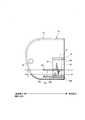
- FIG. 1 is a cross-sectional view of a compartment of a vehicle equipped with a side airbag device, showing a state before deployment.
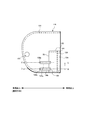
- FIG. 2 is a perspective view showing a seat provided with a side airbag device, and shows a state when the airbag is deployed.
- FIG. 3 is a plan view showing the structure (deployed state / unfolded state) of the side airbag device according to the first embodiment of the present invention, and shows a state seen from the outside of the seat.
- FIG. 4 is a plan view showing the structure (deployed state / non-folded state) of the side airbag device according to the first embodiment, and shows a state seen from the inside of the seat.
- FIG. 1 is a cross-sectional view of a compartment of a vehicle equipped with a side airbag device, showing a state before deployment.
- FIG. 2 is a perspective view showing a seat provided with a side airbag device, and shows a state when the airbag is deployed.
- FIG. 3 is
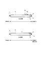
- FIG. 5 is a cross-sectional view in the AA direction and the BB direction in FIG.
- FIG. 6 is a plan view showing a storage state of the side airbag device according to the first embodiment.
- FIG. 7 is a plan view showing a deployed state (actuated state) of the side airbag device according to the first embodiment.
- FIG. 8 is a plan view showing the structure (deployed state / non-folded state) of the side airbag device according to the second embodiment of the present invention, and shows a state seen from the outside of the seat.
- FIG. 9 is a plan view showing the structure (deployed state / non-folded state) of the side airbag device according to the second embodiment, and shows a state seen from the inside of the seat.
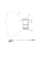
- 10 is a cross-sectional view in the CC direction and the DD direction in FIG.
- FIG. 1 is a cross-sectional view of a compartment portion of a vehicle 10 provided with a side airbag device, and shows a state before deployment.
- FIG. 2 is a perspective view showing a seat provided with a side airbag device, and shows a state when the airbag is deployed.
- FIG. 1 shows a state where the passenger 14 sits down on the seat 16 in the boarding space 12 inside the vehicle 10.
- the side airbag device is mounted in the side surface of the seat 16 and is deployed by an inflation gas supplied from an inflator (not shown).
- the boarding space 12 can be divided into a front area 11, a rear area 13, an upper area 15, and a lower area 17.
- the airbag 18 is shown in a partially inflated state while being deployed from the vehicle seat 16.
- the mounting studs 40a and 40b (see FIG. 4) of the inflator 26 are fixed to the frame of the seat 16 by fasteners (not shown).
- the airbag 18 Prior to operation of the inflator 26, the airbag 18 is folded in a compact form around the inflator 26 in the seat back and covered with an exterior covering the foam (urethane) and the trim material of the seat 16.
- FIG. 3 and 4 are plan views showing the structure (deployed state / non-folded state) of the side airbag device according to the first embodiment of the present invention, as seen from the outside of the seat 16 and seen from the inside of the seat 16. Each state is shown.
- FIG. 5 is a cross-sectional view in the AA direction and the BB direction in FIG.
- the side airbag device includes an airbag (18) that can be inflated and deployed, and an inflator (26) that supplies inflation gas to the airbag (18).
- the airbag is formed into a bag shape, and is mainly provided with a bag main body portion 18 for protecting a passenger in the vehicle; a pocket provided in a part of the bag main body portion 18 and accommodating the bag main body portion 18 therein. 32.
- the pocket 32 can be formed of the same fabric as the bag body 18.
- the bag body portion 18 is formed into a bag shape by folding one piece of cloth into two or overlapping two pieces of cloth and sewing 31 the outer periphery.
- a vent hole 30 is formed in a part of the bag body portion 18 to prevent the internal pressure of the airbag from rising more than necessary.
- the pocket 32 literally has a structure like a trouser pocket.
- the opening 33 is formed only on the front side (deployment direction) of the vehicle, and the other three sides are closed by sewing (31, 35, 42). .
- the folded bag body 18 is accommodated so as to be pushed (inserted) into the pocket 32 from the opening 33, and the bag body 18 can be unfolded from the opening 33 during operation.
- Slits 36a and 36b are formed in the vicinity of the upper and lower ends of the rectangular pocket 32, allowing the pocket 32 to expand when the bag body 18 is deployed, so as not to hinder the deployment of the bag body 18. It has become.
- two string-like tabs 34a and 34b are connected to the pocket 32, and after the bag body 18 is accommodated in the pocket 32, the bag body 18 is held so as not to slide out. Yes.
- the tabs 34a and 34b are formed by cutting out (cutting out) a portion of the pocket 32 and folding it back to the front side of the vehicle (see the upper diagram of FIG. 5). Further, holes 38a and 38b through which stud bolts 40a and 40b (see FIG. 4) of the inflator 26 pass are formed at the tips of the tabs 34a and 34b.
- FIG. 6 and 7 are plan views showing the accommodation state and the deployed state (actuated state) of the side airbag device according to the first embodiment, respectively.
- the bag body 18 is made small by, for example, folding the upper portion of the pocket 32 from the expanded state as shown in FIG. Fold and push into the pocket 32. Thereafter, the stud bolts 40a and 40b of the inflator 26 are passed through the holes 38a and 38b of the tabs 34a and 34b, and the bag body 18 is held. This state is shown in FIG.
- the sensor provided in the vehicle catches the abnormal vibration, An ignition signal is sent to an inflator 26 (not shown) based on the signal. Inside the inflator 26 is provided a propellant that receives the ignition signal from the sensor and drives the inflator 26.
- the bag main body 18 When the inflation gas flows into the bag main body 18 by the operation of the inflator 26, the bag main body 18 is expanded and deployed from the opening 33 of the pocket 32 toward the outside (front of the vehicle). At this time, the tabs 34 a and 34 b are broken near the opening 33 of the pocket 32 so as not to hinder the expansion of the bag body 18. This state is shown in FIG.
- the pocket 32 comes into contact with the urethane portion even in a situation where the outer surface side (FIG. 3 side) of the airbag device faces (contacts) the urethane portion inside the seat 16, urethane is used. It is possible to avoid or suppress the situation where the expansion of the bag body 18 is hindered by friction with the portion. That is, the bag body 18 has already been inflated when it goes out of the opening 33 of the pocket 32, and can be quickly deployed as it is.
- FIG. 8 and 9 are plan views showing the structure (deployed state / unfolded state) of the side airbag device according to the second embodiment of the present invention, as seen from the outside of the seat 16 and seen from the inside of the seat 16. Each state is shown. 10 is a cross-sectional view in the CC direction and the DD direction in FIG.
- the side airbag device includes an airbag (118) that can be inflated and deployed, and an inflator 126 that supplies inflation gas to the airbag (118).
- the airbag is formed into a bag shape, and is mainly provided with a bag main body 118 that protects an occupant in the vehicle; a pocket that is provided in a part of the bag main body 118 and accommodates the bag main body 118 therein. 132.
- the pocket 132 can be molded from the same fabric as the bag body 118.
- the bag body portion 118 is formed into a bag shape by folding one piece of cloth into two, or overlapping two pieces of cloth and sewing 131 the outer periphery.
- a vent hole 130 is formed in a part of the bag main body 118 to prevent the internal pressure of the airbag from rising more than necessary.
- the pocket 132 literally has a structure like a trouser pocket.
- the opening 133 is formed only on the front side (deployment direction) of the vehicle, and the other three sides are closed by sewing (131, 135, 142). .
- the folded bag body 118 is accommodated so as to be pushed (inserted) into the one pocket 32 from the opening 133, and the bag body 118 can be unfolded from the opening 133 during operation.
- slits (36a, 36b) can be formed as in the first embodiment.
- Two string-like tabs 134a and 134b are connected to the pocket 132 by sewing 135, and after the bag main body 118 is received in the pocket 132, the bag main body 118 is held so as not to slide out. ing.
- the tabs 134a and 134b are formed as separate members.
- holes 138a and 138b through which the stud bolts 140a and 140b (see FIG. 9) of the inflator 126 pass are formed at the tips of the tabs 134a and 134b.
- a hole 142 for inserting the inflator 126 into the bag body 118 is formed inside the bag body 118.
- a hole 141 through which the upper bolt 140a of the stud bolts 140a and 140b fixed to the inflator 126 passes is formed.
- One of the features of the present embodiment is that, as shown in FIG. 10, sewing is performed over the entire circumference of the bag main body 118 at a location where the pocket 132 corresponds to the inflator 126 (131, 139, 142, 143). It is that. That is, the bag (fabric) is doubled at the place where the pressure of the inflator 126 is most greatly applied. For this reason, even when the bag main body 118 is damaged by the pressure of the inflation gas, the gas can be prevented from leaking to the outside of the airbag.
- the operation and effects of this embodiment are basically the same as those of the first embodiment described above.
- the bag body 118 is folded into a small size by, for example, folding the upper portion of the pocket 132 from the opened state, then winding it from the front side of the vehicle, folding it in a bellows shape, etc., and pushing it into the pocket 132. Thereafter, the stud bolts 140a and 140b of the inflator 126 are passed through the holes 138a and 138b of the tabs 134a and 134b to hold the bag body 118.
- the sensor provided in the vehicle catches the abnormal vibration, An ignition signal is sent to an inflator 126 (not shown) based on the signal. Inside the inflator 126, a propellant that receives the ignition signal from the sensor and drives the inflator 126 is provided.
- the bag main body 118 When the inflation gas flows into the bag main body 118 by the operation of the inflator 126, the bag main body 118 expands and deploys from the opening 133 of the pocket 132 toward the outside (front of the vehicle). At this time, the tabs 134a and 134b do not hinder the development of the bag body 118 by breaking the sewing portion 135.
- the pocket 132 comes into contact with the urethane portion even in a situation where the outer surface side (FIG. 8 side) of the airbag device faces (contacts) the urethane portion inside the seat 16.
- the situation where the expansion of the bag body 118 is hindered by friction with the urethane portion can be avoided or suppressed. That is, when the bag body 118 goes out of the opening 133 of the pocket 132, the bag body 118 has already been inflated and can be deployed as it is.
- the present invention is not limited to the above-described embodiments, and various design changes and the like can be made without departing from the technical idea described in the claims. is there.
- the side airbag device has been described as an example, but the present invention can be applied to other airbag devices such as a knee airbag device.
- the pocket (32, 132) may have a shape other than a rectangle (triangle, trapezoid, ellipse, etc.).
Landscapes
- Engineering & Computer Science (AREA)
- Mechanical Engineering (AREA)
- Air Bags (AREA)
Abstract
Description
18、118:バッグ本体部
26、126:インフレータ
32、132:ポケット
33、133:開口部
34a,34b,134a,134b:タブ
36a、36b:スリット
Claims (7)
- 膨張展開可能なエアバッグと、前記エアバッグに膨張ガスを供給するインフレータとを備えたエアバッグ装置において、
前記エアバッグは、袋状に成形され、主に車両内の乗員を保護するバッグ本体部と;
前記バッグ本体部の一部に設けられ、当該バッグ本体部をその中に収容するポケットとを備えたことを特徴とするエアバッグ装置。 - 前記ポケットは、前記インフレータ周辺に設けられたファブリック製のポケットであることを特徴とする請求項1に記載のエアバッグ装置。
- 前記ポケットは、前記バッグ本体部の展開方向端部とは逆の固定部側の縁部付近に設けられ、
少なくとも、前記バッグ本体部の展開方向端部側が開放されていることを特徴とする請求項1又は2に記載のエアバッグ装置。 - 前記ポケットは、前記バッグ本体部の展開時に伸縮可能にすべく、一部にスリットが形成されていることを特徴とする請求項1乃至3の何れかに記載のエアバッグ装置。
- 前記ポケットには、収容された前記バッグ本体部を保持するタブが設けられていることを特徴とする請求項1乃至4の何れかに記載のエアバッグ装置。
- 前記インフレータには車両の一部に対して固定する固定具が設けられ、当該固定具は前記エアバッグを貫通する構造であり、
前記タブの一部が前記固定具に係止されることを特徴とする請求項5に記載のエアバッグ装置。 - 前記ポケットは、前記インフレータに対応する箇所において、前記バッグ本体部に対して全周に渡って縫製されていることを特徴とする請求項1乃至6の何れかに記載のエアバッグ装置。
Priority Applications (2)
| Application Number | Priority Date | Filing Date | Title |
|---|---|---|---|
| JP2011543274A JP5543491B2 (ja) | 2009-11-30 | 2010-11-24 | エアバッグ装置 |
| CN201080054364.8A CN102639367B (zh) | 2009-11-30 | 2010-11-24 | 安全气囊装置 |
Applications Claiming Priority (2)
| Application Number | Priority Date | Filing Date | Title |
|---|---|---|---|
| JP2009-272684 | 2009-11-30 | ||
| JP2009272684 | 2009-11-30 |
Publications (1)
| Publication Number | Publication Date |
|---|---|
| WO2011065385A1 true WO2011065385A1 (ja) | 2011-06-03 |
Family
ID=44066490
Family Applications (1)
| Application Number | Title | Priority Date | Filing Date |
|---|---|---|---|
| PCT/JP2010/070945 Ceased WO2011065385A1 (ja) | 2009-11-30 | 2010-11-24 | エアバッグ装置 |
Country Status (3)
| Country | Link |
|---|---|
| JP (1) | JP5543491B2 (ja) |
| CN (1) | CN102639367B (ja) |
| WO (1) | WO2011065385A1 (ja) |
Cited By (4)
| Publication number | Priority date | Publication date | Assignee | Title |
|---|---|---|---|---|
| JP2018052275A (ja) * | 2016-09-28 | 2018-04-05 | 豊田合成株式会社 | 車両用エアバッグ装置及び車両用エアバッグ装置に用いられるラッピング材 |
| WO2018105335A1 (ja) * | 2016-12-05 | 2018-06-14 | オートリブ ディベロップメント エービー | サイドエアバッグ装置 |
| US20190039560A1 (en) * | 2017-08-03 | 2019-02-07 | Toyoda Gosei Co., Ltd. | Airbag device |
| US11338759B2 (en) * | 2019-08-09 | 2022-05-24 | Autoliv Development Ab | Airbag device |
Citations (6)
| Publication number | Priority date | Publication date | Assignee | Title |
|---|---|---|---|---|
| JPH09193734A (ja) * | 1996-01-19 | 1997-07-29 | Toyo Tire & Rubber Co Ltd | 側部用エアバッグ装置 |
| JPH1067290A (ja) * | 1996-06-24 | 1998-03-10 | Takata Inc | 一体化された拘束システムのためのクッションサブモジュール及び空気入れ |
| JP2000095057A (ja) * | 1998-09-18 | 2000-04-04 | Honda Motor Co Ltd | エアバッグ装置 |
| JP2003104155A (ja) * | 2001-09-28 | 2003-04-09 | Toyoda Gosei Co Ltd | エアバッグ装置 |
| JP2006508846A (ja) * | 2002-12-03 | 2006-03-16 | タカタ株式会社 | 車両乗員保護システム用のガスバッグ |
| JP2009023640A (ja) * | 2007-07-20 | 2009-02-05 | Tk Holdings Inc | マルチチャンバ式サイドエアバッグ |
Family Cites Families (3)
| Publication number | Priority date | Publication date | Assignee | Title |
|---|---|---|---|---|
| US5628527A (en) * | 1996-01-25 | 1997-05-13 | Morton International, Inc. | Cover/director for air bag |
| DE10157784C1 (de) * | 2001-11-27 | 2003-08-21 | Autoliv Dev | Airbagmodul mit einem Deflektor-Halteteil |
| JP4898271B2 (ja) * | 2006-04-18 | 2012-03-14 | タカタ株式会社 | エアバッグ装置、車両、エアバッグ装置の製造方法 |
-
2010
- 2010-11-24 JP JP2011543274A patent/JP5543491B2/ja not_active Expired - Fee Related
- 2010-11-24 WO PCT/JP2010/070945 patent/WO2011065385A1/ja not_active Ceased
- 2010-11-24 CN CN201080054364.8A patent/CN102639367B/zh not_active Expired - Fee Related
Patent Citations (6)
| Publication number | Priority date | Publication date | Assignee | Title |
|---|---|---|---|---|
| JPH09193734A (ja) * | 1996-01-19 | 1997-07-29 | Toyo Tire & Rubber Co Ltd | 側部用エアバッグ装置 |
| JPH1067290A (ja) * | 1996-06-24 | 1998-03-10 | Takata Inc | 一体化された拘束システムのためのクッションサブモジュール及び空気入れ |
| JP2000095057A (ja) * | 1998-09-18 | 2000-04-04 | Honda Motor Co Ltd | エアバッグ装置 |
| JP2003104155A (ja) * | 2001-09-28 | 2003-04-09 | Toyoda Gosei Co Ltd | エアバッグ装置 |
| JP2006508846A (ja) * | 2002-12-03 | 2006-03-16 | タカタ株式会社 | 車両乗員保護システム用のガスバッグ |
| JP2009023640A (ja) * | 2007-07-20 | 2009-02-05 | Tk Holdings Inc | マルチチャンバ式サイドエアバッグ |
Cited By (5)
| Publication number | Priority date | Publication date | Assignee | Title |
|---|---|---|---|---|
| JP2018052275A (ja) * | 2016-09-28 | 2018-04-05 | 豊田合成株式会社 | 車両用エアバッグ装置及び車両用エアバッグ装置に用いられるラッピング材 |
| WO2018105335A1 (ja) * | 2016-12-05 | 2018-06-14 | オートリブ ディベロップメント エービー | サイドエアバッグ装置 |
| US20190039560A1 (en) * | 2017-08-03 | 2019-02-07 | Toyoda Gosei Co., Ltd. | Airbag device |
| US10793101B2 (en) * | 2017-08-03 | 2020-10-06 | Toyoda Gosei Co., Ltd. | Airbag device |
| US11338759B2 (en) * | 2019-08-09 | 2022-05-24 | Autoliv Development Ab | Airbag device |
Also Published As
| Publication number | Publication date |
|---|---|
| JP5543491B2 (ja) | 2014-07-09 |
| JPWO2011065385A1 (ja) | 2013-04-18 |
| CN102639367B (zh) | 2014-06-25 |
| CN102639367A (zh) | 2012-08-15 |
Similar Documents
| Publication | Publication Date | Title |
|---|---|---|
| US6942242B2 (en) | Biasing deployment flap and inflatable cushion cover | |
| US7549671B2 (en) | Knee-protecting airbag apparatus | |
| JP5149383B2 (ja) | エアバッグ装置 | |
| US20080217887A1 (en) | Airbag protection flap | |
| US9849858B2 (en) | Airbag device | |
| CN101765528B (zh) | 气囊及气囊装置 | |
| CN109963754B (zh) | 侧气囊装置 | |
| JP6217447B2 (ja) | エアバッグ装置 | |
| JP2000142307A (ja) | 車両用エアバッグ装置 | |
| JP6305746B2 (ja) | エアバッグ及びエアバッグ装置 | |
| JP2007022265A (ja) | 頭部保護エアバッグ装置 | |
| KR100598685B1 (ko) | 커튼에어백 장착구조 | |
| JP5543491B2 (ja) | エアバッグ装置 | |
| JP2011240884A (ja) | カーテンエアバッグ装置 | |
| CN116261536A (zh) | 侧面安全气囊装置 | |
| WO2013146076A1 (ja) | 頭部保護エアバッグ装置 | |
| CN117460649A (zh) | 具有辅助展开包裹件的正面安全气囊系统 | |
| JP6327112B2 (ja) | サイドエアバッグ装置 | |
| JP7209924B2 (ja) | カーテンシールドエアバッグ装置 | |
| JP4793911B2 (ja) | エアバッグ装置 | |
| JP6111054B2 (ja) | カーテンエアバッグ装置 | |
| JP2005271703A (ja) | 膝保護用エアバッグ装置 | |
| WO2020116024A1 (ja) | エアバッグ装置 | |
| JP7554977B2 (ja) | 車両用エアバッグ装置 | |
| JP7726150B2 (ja) | 車両ルーフサイド構造 |
Legal Events
| Date | Code | Title | Description |
|---|---|---|---|
| WWE | Wipo information: entry into national phase |
Ref document number: 201080054364.8 Country of ref document: CN |
|
| 121 | Ep: the epo has been informed by wipo that ep was designated in this application |
Ref document number: 10833231 Country of ref document: EP Kind code of ref document: A1 |
|
| WWE | Wipo information: entry into national phase |
Ref document number: 2011543274 Country of ref document: JP |
|
| WWE | Wipo information: entry into national phase |
Ref document number: 4246/CHENP/2012 Country of ref document: IN |
|
| NENP | Non-entry into the national phase |
Ref country code: DE |
|
| 122 | Ep: pct application non-entry in european phase |
Ref document number: 10833231 Country of ref document: EP Kind code of ref document: A1 |