US10793101B2 - Airbag device - Google Patents
Airbag device Download PDFInfo
- Publication number
- US10793101B2 US10793101B2 US16/045,854 US201816045854A US10793101B2 US 10793101 B2 US10793101 B2 US 10793101B2 US 201816045854 A US201816045854 A US 201816045854A US 10793101 B2 US10793101 B2 US 10793101B2
- Authority
- US
- United States
- Prior art keywords
- airbag
- inflator
- slit
- panel
- holes
- Prior art date
- Legal status (The legal status is an assumption and is not a legal conclusion. Google has not performed a legal analysis and makes no representation as to the accuracy of the status listed.)
- Active, expires
Links
- 238000003780 insertion Methods 0.000 claims abstract description 53
- 230000037431 insertion Effects 0.000 claims abstract description 53
- 239000000463 material Substances 0.000 claims description 11
- 230000003014 reinforcing effect Effects 0.000 description 41
- 210000002105 tongue Anatomy 0.000 description 29
- 230000002093 peripheral effect Effects 0.000 description 14
- 230000000694 effects Effects 0.000 description 8
- 239000004744 fabric Substances 0.000 description 7
- 230000004048 modification Effects 0.000 description 5
- 238000012986 modification Methods 0.000 description 5
- 229910052751 metal Inorganic materials 0.000 description 3
- 239000002184 metal Substances 0.000 description 3
- 239000004952 Polyamide Substances 0.000 description 2
- 239000011248 coating agent Substances 0.000 description 2
- 229920002647 polyamide Polymers 0.000 description 2
- 229920000728 polyester Polymers 0.000 description 2
- 238000009958 sewing Methods 0.000 description 2
- 229920003002 synthetic resin Polymers 0.000 description 2
- 239000000057 synthetic resin Substances 0.000 description 2
- 239000002759 woven fabric Substances 0.000 description 2
- 229910000838 Al alloy Inorganic materials 0.000 description 1
- 229910000831 Steel Inorganic materials 0.000 description 1
- 229910052782 aluminium Inorganic materials 0.000 description 1
- XAGFODPZIPBFFR-UHFFFAOYSA-N aluminium Chemical compound [Al] XAGFODPZIPBFFR-UHFFFAOYSA-N 0.000 description 1
- WABPQHHGFIMREM-UHFFFAOYSA-N lead(0) Chemical compound [Pb] WABPQHHGFIMREM-UHFFFAOYSA-N 0.000 description 1
- 229920000098 polyolefin Polymers 0.000 description 1
- 239000010959 steel Substances 0.000 description 1
- 229920002725 thermoplastic elastomer Polymers 0.000 description 1
Images


Classifications
-
- B—PERFORMING OPERATIONS; TRANSPORTING
- B60—VEHICLES IN GENERAL
- B60R—VEHICLES, VEHICLE FITTINGS, OR VEHICLE PARTS, NOT OTHERWISE PROVIDED FOR
- B60R21/00—Arrangements or fittings on vehicles for protecting or preventing injuries to occupants or pedestrians in case of accidents or other traffic risks
- B60R21/34—Protecting non-occupants of a vehicle, e.g. pedestrians
- B60R21/36—Protecting non-occupants of a vehicle, e.g. pedestrians using airbags
-
- B—PERFORMING OPERATIONS; TRANSPORTING
- B60—VEHICLES IN GENERAL
- B60R—VEHICLES, VEHICLE FITTINGS, OR VEHICLE PARTS, NOT OTHERWISE PROVIDED FOR
- B60R21/00—Arrangements or fittings on vehicles for protecting or preventing injuries to occupants or pedestrians in case of accidents or other traffic risks
- B60R21/02—Occupant safety arrangements or fittings, e.g. crash pads
- B60R21/16—Inflatable occupant restraints or confinements designed to inflate upon impact or impending impact, e.g. air bags
- B60R21/20—Arrangements for storing inflatable members in their non-use or deflated condition; Arrangement or mounting of air bag modules or components
- B60R21/217—Inflation fluid source retainers, e.g. reaction canisters; Connection of bags, covers, diffusers or inflation fluid sources therewith or together
Definitions
- the present invention relates to an airbag device adapted to be mounted on a vehicle. More particularly, the invention relates to an airbag device that includes an airbag inflatable with an inflation gas and an inflator for feeding the inflation gas to the airbag.
- JP 2017-81248 A discloses a known airbag device which includes an airbag inflatable with an inflation gas and an inflator for feeding the inflation gas to the airbag.
- the inflator is formed into a cylinder and provided with a mounting member which protrudes from an outer circumference of the inflator.
- the inflator is stored inside the airbag such that the mounting member protrudes from the airbag, and the airbag and inflator are mounted on a vehicle body structure by fixing the mounting member to the vehicle body structure.
- the airbag includes an insert opening via which the inflator is inserted into the airbag.
- the insert opening of this airbag is composed of a combination of two slits. Specifically, an area of the airbag provided with the insert opening has a double wall structure, and each of the walls includes a slit such that the two slits intersect each other to form the insert opening.
- the airbag further includes a cover cloth that covers the insert opening from the outside.
- the inflator is inserted into one of the slits and the other from its first end.
- the inflator is stored in the airbag such that the first end region is placed inside the airbag and a second end region protrudes out of the insert opening.
- the object of the present invention is to provide an airbag device that is capable of preventing gas leakage from an airbag despite the configuration that an inflator is stored inside the airbag.
- the airbag device includes an airbag inflatable with an inflation gas, and an inflator that is stored inside the airbag for feeding the airbag with the inflation gas.
- the inflator includes an inflator body that is generally cylindrical in outer contour and placed inside the airbag and a mounting member that protrudes from an outer circumference of the inflator body generally orthogonally to an axial direction of the inflator body, and protrudes out of the airbag to be mounted on a body structure of a vehicle in order to mount the airbag and inflator body on the body structure of the vehicle.
- the airbag includes an insertion region via which the inflator is inserted into the airbag.
- the insertion region has a double wall structure of an outer panel and an inner panel each formed of a flexible sheet material.
- the insertion region includes an outer slit and an inner slit for receiving the inflator, and one or more through holes that are formed through the outer panel and inner panel and allow the mounting member of the inflator to protrude out of the airbag.
- the outer slit is formed on the outer panel
- the inner slit is formed on the inner panel
- the outer slit and inner slit are so arranged as not to overlap or intersect each other.
- the insertion region of the airbag has a double wall structure of the outer panel and inner panel, and the outer slit formed on the outer panel and the inner slit formed on the inner panel are arranged so as not to overlap or intersect each other.
- This configuration will prevent an inflation gas which has flown into the airbag from leaking from the inner silt or outer slit, since the outer slit and its peripheral area disposed on the outer panel is covered by the inner panel whereas the inner slit and its peripheral area disposed on the inner panel is covered by the outer panel.
- the airbag device of the invention is capable of preventing a gas leakage from the airbag adequately despite the configuration that the inflator is stored inside the airbag.
- the outer slit and inner slit are each formed into straight lines which are generally parallel to each other. This configuration will facilitate an inserting work of the inflator body in comparison with an instance where the outer slit and inner slit are not parallel.
- the outer slit and inner slit are so formed as to extend generally in parallel to an axial direction of the inflator body at positions dislocated each other in a circumferential direction of the inflator body.
- the inserting work of the inflator body into the outer slit and inner slit and a work of taking the mounting members out of the through holes can be easily conducted merely by rotating the inflator body back and forth about the center in the axial direction.
- the insertion region includes a lid panel that has flexibility and covers the outer slit on outside of the outer panel, and that the lid panel is joined to the outer panel by the first end region, and is provided, in a vicinity of the second end, with one or more mounting holes each of which communicates with each of the through holes and receives the mounting member of the inflator. Covering the outer slit from the outside, such a lid panel will prevent an inflation gas which has flown into the airbag from leaking from the outer slit, thus further help prevent a gas leakage from the airbag.
- the airbag further includes an inner tube that is formed into a tube having flexibility and covers an outer circumference of the inflator body inside the airbag, and that the inner tube includes a tube body that covers the inflator body and includes one or more outlet ports for releasing the inflation gas as exited the inflator body, and a cover region that is joined to the tube body at the first end region and extends from the tube body in order to cover the inner slit from an inner side of the airbag.
- the inner tube configured as described above will deliver the gas into the airbag via the outlet ports of the tube body such that the gas may not head towards the inner slit. Further, since the second end of the cover region is a free end, the inflation gas will press the cover region against the inner surface of the inner panel to close off the inner slit, such that the gas will be prevented from leaking from the inner slit. Thus, a gas leakage from the airbag will be further adequately prevented.
- the outer slit and the inner slit are disposed on a same side with respect to the through holes, as viewed from an axial direction of the inflator body.
- this configuration will enhance a strength of a peripheral area of the through holes in the airbag.
- the inner slit is positioned closer to the through holes than the outer slit.
- This configuration will facilitate the inserting work of the inflator, which is composed of inserting the inflator through the outer slit, then the inner slit, and taking the mounting members of the inflator out of the through holes, in comparison with an instance where the outer slit is positioned closer to the through holes than the inner slit. That is, with the above configuration, when the inflator is put into the airbag via the outer slit, then inner slit, the mounting members are disposed near the through holes, thus can be taken out of the through holes easily.
- the airbag device of the invention may be preferably provided with a guide member that is disposed between the outer panel and the inner panel for assisting with an inserting work of the inflator.
- the guide member is formed of a flexible sheet material, and is put through the inner slit and arranged such that the first end is disposed at a position between the outer slit and inner slit on the inner surface of the outer panel whereas the second end region is placed over the inner surface of the inner panel.
- the first end region of the guide member is joined to the outer panel.
- such a guide member When putting the inflator body into the airbag via the inner slit, such a guide member will close off a gap between the outer panel and inner panel, prevent the inflator body from going into the gap and smoothly guide the inflator body into the inner slit. That is, the guide member will facilitate an inserting work of the inflator body into the airbag.
- the above airbag device having the guide member may be provided with such a lid panel that has flexibility and covers the outer slit on outside of the outer panel, and is joined to the outer panel by the first end region.
- the lid panel includes, in a vicinity of the second end, one or more mounting holes each of which communicates with each of the through holes of the insertion region and receives the mounting member of the inflator. Covering the outer slit from the outside, the lid panel will prevent an inflation gas which has flown into the airbag from leaking from the outer slit, thus further helps prevent a gas leakage from the airbag.
- the outer slit and inner slit are each formed into straight lines which are generally parallel to each other. This configuration will facilitate the inserting work of the inflator body in comparison with an instance where the outer slit and inner slit are not parallel.
- the outer slit and inner slit are so formed as to extend generally in parallel to an axial direction of the inflator body at positions dislocated from the inflator body in a circumferential direction of the inflator body.
- the inserting work of the inflator body into the outer slit and inner slit and the work of taking the mounting members out of the through holes can be easily conducted merely by rotating the inflator body back and forth about the center in the axial direction.
- the lid panel may be put through the outer slit such that the first end region of the lid panel is disposed on the inner surface of the outer panel.
- the airbag device configured as described above, it is also conceivable to form the airbag without a lid panel for covering the outer slit and form the through holes between the outer slit and inner slit.
- the region of the airbag between the outer slit and inner slit will be held down by the inflator body, thus a gas leakage will be adequately prevented even though the airbag does not include a lid panel.
- the outer slit and the inner slit may be disposed on a same side with respect to the through holes, as viewed from an axial direction of the inflator body. In comparison with an instance where the outer slit and inner slit are each disposed on one side and the other with respect to the through holes, this configuration will enhance a strength of a peripheral area of the through holes in the airbag.
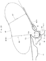
- FIG. 1 is a plan view of a vehicle equipped with an airbag device for pedestrian protection embodying the invention
- FIG. 2 is a schematic vertical sectional view of the airbag device of FIG. 1 taken along a front and rear direction;
- FIG. 3 is a schematic enlarged vertical sectional view of the airbag device of FIG. 1 taken along the front and rear direction, especially showing an inflator;
- FIG. 4 is a schematic vertical sectional view of the airbag device of FIG. 1 taken along a left and right direction, especially showing the inflator;
- FIG. 5 is a plan view of an airbag for use in the airbag device of the embodiment as laid flat;
- FIG. 6 is a bottom view of the airbag of FIG. 5 ;
- FIG. 7 is a sectional view of the airbag of FIG. 5 as inflated by itself, taken along line VII-VII of FIG. 6 ;
- FIG. 8 is a sectional view of the airbag of FIG. 5 as inflated by itself, taken along line VIII-VIII of FIG. 6 ;
- FIG. 9 is a partial enlarged bottom view of an insertion region of the airbag of FIG. 5 ;
- FIG. 10 is a partial enlarged sectional view of the airbag of FIG. 5 showing the insertion region and an inner tube;
- FIG. 11 is a schematic exploded perspective view of the insertion region
- FIG. 12 is a bottom view of the inner tube as laid flat
- FIG. 13 is a vertical sectional view of the inner tube of FIG. 12 ;
- FIG. 14 is a partial enlarged bottom view of the airbag of FIG. 5 showing a mounting tongue
- FIG. 15 is a sectional view taken along line XV-XV of FIG. 14 ;
- FIG. 16 is a sectional view taken along line XVI-XVI of FIG. 14 ;
- FIG. 17 is a vertical sectional view of the mounting tongue as mounted on a case, taken along a front and rear direction;
- FIG. 18 is a vertical sectional view of the mounting tongue as mounted on the case, taken along a left and right direction;
- FIGS. 19 and 20 depict base cloths of the airbag of FIG. 5 in plan views
- FIG. 21 is a schematic plan view of the airbag device of the embodiment as has completed airbag deployment
- FIG. 22 is a schematic partial enlarged vertical sectional view of the airbag device as has completed airbag deployment, especially showing the inflator and its vicinity;
- FIG. 23 is a schematic vertical sectional view of the airbag device as has completed airbag deployment, taken at the location of the mounting tongue;
- FIG. 24 is a partial enlarged bottom view of an insertion region in a modification of the airbag of the invention.
- FIG. 25 is a partial enlarged sectional view of the airbag of FIG. 24 showing the insertion region and an inner tube;
- FIG. 26 is a schematic exploded perspective view of the insertion region in the airbag of FIG. 24 ;
- FIG. 27 is a partial enlarged sectional view of another modification of the airbag of the invention showing an insertion region and an inner tube;
- FIG. 28 is a partial enlarged sectional view of yet another modification of the airbag of the invention showing an insertion region and an inner tube;
- FIG. 29 is a partial enlarged bottom view of an insertion region of a further modification of the airbag of the invention.
- the airbag device M is disposed in a vicinity of a rear end 15 c of a hood 15 of a vehicle V, as shown in FIGS. 1 to 3 . More particularly, the airbag device M is disposed proximate to and at the rear of the rear end 15 c of the hood 15 , generally at the center in a left and right direction of the vehicle V between left and right front pillars 5 L and 5 R. Unless otherwise specified, front/rear, up/down and left/right directions in this description are intended to refer to front/rear, up/down and left/right directions of the vehicle V.
- the vehicle V is provided, inside the front bumper 6 ( FIG. 1 ), with a not-shown sensor for detecting an impact against a pedestrian.
- the vehicle V is also provided with a not-shown actuating circuit which is connected with the sensor.
- the actuating circuit actuates an inflator 30 of the airbag device M in response to a signal fed from the sensor that has detected an impact against a pedestrian.
- the hood 15 covers an engine room of the vehicle V and is joined to the body structure 1 of the vehicle V with not-shown hinge sections in such a manner as to be openable forward.
- the hinge sections are located at the left and right edges of the rear end 15 c region of the hood 15 .
- the hood 15 of the illustrated embodiment is fabricated of a steel plate, a plate material of aluminum (aluminum alloy) or the like, and is composed of an outer panel 15 a , which forms a top face, and an inner panel 15 b , which forms a lower face and has a higher strength than the outer panel 15 a , as shown in FIGS. 2 and 3 . As shown in FIG.
- the rear end 15 c region of the hood 15 is so shaped as to curve with respect to a left and right direction such that the center in a left and right direction is disposed forward whereas left and right end regions are disposed rearward.
- the cowl 7 is composed of a cowl panel 7 a which has high rigidity and belongs to the vehicle body structure 1 , and a cowl louver 7 b which is disposed above the cowl panel 7 a and is fabricated of synthetic resin.
- the cowl louver 7 b is continuous with a lower region 4 a of the front windshield 4 at the rear end.
- the cowl 7 is also shaped along the curvature of the rear end 15 c of the hood 15 to curve relative to the left and right direction such that the central region in a left and right direction is disposed forward whereas the left and right end regions are disposed rearward ( FIG. 1 ). As shown in FIG.
- a pair of wipers 8 are disposed on the cowl 7 . As indicated with double-dotted lines in FIGS. 2 and 3 , the wipers 8 are so disposed as to protrude upward from the cowl louver 7 b .
- the front pillars 5 L and 5 R are disposed on the left and right of the front windshield 4 .
- the airbag device M includes an airbag 45 , an inflator 30 that feeds an inflation gas to the airbag 45 , a case 20 that houses the airbag 45 and inflator 30 , an airbag cover 25 for covering the airbag 45 , and a mounting bracket 100 that mounts later-described mounting tongues 72 ( 72 L, 72 R) of the airbag 45 on the case 20 .
- the case 20 is formed of a sheet metal into an open-topped box shape.
- the case 20 is formed of a sheet metal, and includes a bottom wall 21 , a circumferential wall 22 which rises from the circumferential edge of the bottom wall 21 in a generally square tubular shape, and an emergence opening 20 a which is disposed at the top of the circumferential wall 22 for allowing airbag emergence.
- the bottom wall 21 is provided with a plurality of mounting holes 21 a for receiving later-described mounting bolts 39 for mounting the inflator 30 and later-described mounting bolts 102 for mounting the mounting tongues 72 of the airbag 45 , as shown in FIGS. 2 to 4, 17, 18 and 22 .
- the bottom wall 21 of the case 20 serves as a member of the vehicle body structure 1 on which the inflator 30 is mounted.
- the case 20 is mounted on the cowl panel 7 a through the use of not-shown mounting brackets such that a front region of the case 20 is disposed immediately beneath the rear end 15 c of the hood 15 and a rear region of the case 20 is disposed at the rear of the hood 15 .
- the case 20 is also shaped along the curvature of the rear end 15 c of the hood 15 to curve relative to the left and right direction such that the central region in a left and right direction is disposed forward whereas the left and right end regions are disposed rearward ( FIG. 1 ).
- the airbag cover 25 is formed from soft synthetic resin such as thermoplastic elastomer of polyolefin (TPO). As shown in FIGS. 2, 3, 22 and 23 , the airbag cover 25 covers the emergence opening 20 a of the case 20 , and includes a door section 26 which is openable for allowing airbag emergence when pushed by the airbag 45 .
- the airbag cover 25 is fixed to the case 20 at predetermined portions with not-shown mounting means.
- the inflator 30 includes a body 31 and a mounting bracket 35 used to mount the body 31 to the case 20 .
- the inflator body 31 is formed generally into a cylinder, and placed inside a later-described airbag body 46 of the airbag 46 . More specifically, as indicated with double-dotted lines in FIGS. 5 and 6 , the inflator body 31 is arranged to extend along a left and right direction at a generally center in a front and rear direction and in a left and right direction of a later-described transverse inflatable portion 48 of the airbag 45 , inside the airbag 45 .
- the inflator body 31 includes a gas releasing region 32 at the first end in the axial direction (or leading end, or left end, in the illustrated embodiment) 31 a .
- the gas releasing section 32 is provided with numerous gas releasing ports which discharge an inflation gas.
- the second end (or root end, or right end, in the illustrated embodiment) 31 b of the inflator 30 is electrically connected to the actuating circuit through a not-shown lead wire.
- the mounting bracket 35 includes a supporting section 36 which supports an underside of the inflator body 31 and a plurality of (three, in the illustrated embodiment) mounting bolts 39 which protrude downwardly from the supporting section 36 .
- the supporting section 36 is formed of a sheet metal into a band extending generally along a left and right direction (or along an axial direction of the inflator body 31 ).
- the supporting section 36 is provided, at more than one (three, in the illustrated embodiment) positions in the left and right direction, with a plurality of pairs of support tongues 37 which support the inflator 30 .
- the support tongues 37 extend diagonally upward and outwardly in a front and rear direction from the front and rear edges of the supporting section 36 so as to support an outer circumference 31 c of the inflator body 31 .
- the front and rear support tongues 37 are symmetrical in the front and rear direction, as shown in FIG. 3 .
- the three pairs of the supporting tongues 37 are disposed at the same location as the mounting bolts 39 .
- the mounting bolts 39 are disposed at three positions; at a vicinity of each of left and right ends of the supporting section 36 , and at a generally center in a left and right direction of the supporting section 36 .
- the mounting bracket 35 and inflator body 31 are coupled together with the aid of a plurality of (two, in the illustrated embodiment) clamps 40 ( FIG. 4 ), which are mounted around the mounting bracket 35 and inflator body 31 at a vicinity of each of left and right ends of the inflator body 31 .
- the inflator 30 of the illustrated embodiment is an assembled structure of the inflator body 31 and mounting bracket 35 .
- the mounting bolts (i.e. mounting member) 39 protrude from the outer circumference 31 c of the inflator body 31 generally orthogonally to the axis of the inflator body 31 (i.e. downwardly).
- the inflator 30 is stored inside the airbag 45 such that the mounting bolts 39 protrude from later-described insert holes 55 of the airbag 45 and later-described mounting holes 62 of a lid panel 58 , as indicated with double-dotted lines in FIG. 7 .
- the inflator body 31 and the supporting section 36 of the mounting bracket 35 are stored inside the airbag 45 .
- the inflator 30 is mounted on the bottom wall 21 of the case 20 (i.e. on a part of the vehicle body structure), together with the airbag 45 . More particularly, the inflator 30 and airbag 45 are mounted on the bottom wall 21 of the case 20 by nut 42 fastening of the mounting bolts 39 which protrude from the bottom wall 21 of the case 20 via the mounting holes 62 of the lid panel 58 , as shown in FIG. 3 . Further, in the illustrated embodiment, the inflator 30 , i.e. the assembled structure of the inflator body 31 and mounting bracket 35 , are covered with a tube body 81 of a later-described inner tube 80 inside the airbag 45 , as best shown in FIG. 7 .
- the airbag 45 includes a bag body 46 which is inflatable with an inflation gas, a mounting tongue 72 by which the bag body 46 is mounted on the case 20 , and an inner tube 80 which covers an outer circumference of the inflator 30 inside the bag body 46 .
- the bag body 46 includes an insertion region 49 via which the inflator 30 is inserted into the bag body 46 .
- the bag body 46 is designed to be inflated into a generally U shape elongated in a left and right direction, as viewed from the front.
- the bag body 46 as deployed includes a transverse inflatable portion 48 that extends generally along the left and right direction, along the lower region 4 a of the front windshield 4 , and a pair of vertical inflatable portions 65 L and 65 R that extend rearward from opposite ends of the transverse inflatable portion 48 and cover the lower regions 5 a of the front pillars 5 L and 5 R.
- the bag body 46 includes a pedestrian-side wall 46 b deployable on the upper side and a vehicle-side wall 46 a deployable on the lower side and opposed to the pedestrian-side wall 46 b .
- the bag body 46 is formed by joining (sewing) outer circumferential edges of the pedestrian-side wall 46 b and vehicle-side wall 46 a together.
- the transverse inflatable portion 48 is designed to be deployed over the rear end 15 c region of the hood 15 , the cowl 7 and the lower region 4 a of the front windshield 4 including the wipers 8 , as shown in FIGS. 21 and 23 .
- the inflator 30 is to be stored in a central area in the front and rear direction and in the left and right direction of the transverse inflatable portion 48 , and a generally central area in the front and rear direction and in the left and right direction of the vehicle-side wall 46 a in the transverse inflatable portion 48 serves as an insertion region 49 , via which the inflator 30 is inserted into the airbag 45 ( FIG. 6 ).
- the insertion region 49 is disposed between a front center tether 68 and a rear center tether 67 and between side tethers 69 L and 69 R as described later, i.e. generally in the central area in the front and rear direction and in the left and right direction of the vehicle-side wall 46 a .
- the insertion region 49 is reinforced by a reinforcing panel 51 on the inner side. That is, the insertion region 49 has a double wall structure of the vehicle-side wall (outer panel) 46 a and the reinforcing panel (inner panel) 51 , as shown in FIGS. 9 and 10 .
- the reinforcing panel 51 serving as the inner panel has a rectangular shape large enough to cover the insertion region 49 all over.
- the front edge 51 a and rear edge 51 b of the reinforcing panel 51 are joined (sewn) to the vehicle-side wall 46 a together with the front center tether 68 and rear center tether 67 , as shown in FIG. 7 .
- the width W 1 ( FIG. 9 ) in a left and right direction of the reinforcing panel 51 is greater than the length L 1 ( FIG. 4 ) of the inflator body 31 and the width W 4 ( FIG. 12 ) in a left and right direction of the tube body 81 of the inner tube 80 , and is approximately one third of the width W 2 ( FIG. 6 ) in the left and right direction of the bag body 46 as laid flat.
- the insertion region 49 includes an outer slit 53 which is formed on the vehicle-side wall (i.e. outer panel) 46 a , an inner slit 54 which is formed on the reinforcing panel (i.e. inner panel) 51 , three through holes 55 which are formed through the vehicle-side wall 46 a and reinforcing panel 51 , and a lid panel 58 which is disposed on outside of the vehicle-side wall 46 a.
- the outer slit 53 and inner slit 54 constitute an inlet of the inflator 30 (or inflator body 31 ) in combination.
- each of the outer slit 53 and inner slit 54 is formed into a straight line extending along the axial direction of the inflator body 31 , i.e. generally along a left and right direction.
- the outer slit 53 and inner slit 54 are dislocated from each other in a front and rear direction (in other words, in a circumferential direction of the inflator body 31 as mounted on board) and arranged in a non-intersecting fashion.
- the outer slit 53 and inner slit 54 are generally in parallel.
- the inner slit 54 formed on the reinforcing panel 51 is disposed farther to the front than the outer slit 53 .
- the outer slit 53 and inner slit 54 have different length. Specifically, the length L 2 of the outer slit 53 is slightly smaller than the length L 3 of the inner slit 54 , as shown in FIGS. 9 and 11 .
- the length L 2 of the outer slit 53 is smaller than the length of a joint 59 which joins (sews) a rear end 58 b region of the lid panel 58 to the vehicle-side wall 46 a .
- the length L 3 of the inner slit 54 is generally identical to a distance D 1 ( FIG.
- the length L 3 of the inner slit 54 is smaller than the length L 1 of the inflator body 31 and smaller than the width W 3 in a left and right direction of the lid panel 58 . More particularly, the length L 3 is approximately four sevenths of the length L 1 of the inflator body 31 , and the length L 2 of the outer slit 53 is approximately a half of the length L 1 of the inflator body 31 .
- the lengths L 2 and L 3 of the outer slit 53 and inner slit 54 are determined to be as small as possible to such an extent that enables a smooth entry of the inflator 30 (i.e. the assembled structure of the inflator body 31 and mounting bracket 35 ).
- the inner slit 54 is slightly greater in length than the outer slit 53 in consideration of easiness of insertion of the inflator 30 after having passed through the outer slit 53 .
- the outer slit 53 and inner slit 54 are disposed at the rear of the inflator body 31 , within a range of the width of the inflator body 31 in the left and right direction, as shown in FIGS. 9 and 10 .
- the distance D 2 ( FIG. 9 ) between the outer slit 53 and inner slit 54 as the bag body 46 is laid flat is generally identical to the outer diameter D 3 ( FIG. 3 ) of the inflator body 31 .
- Each of the through holes 55 is formed through the reinforcing panel 51 and vehicle-side wall 46 a at three positions in the left and right direction for receiving the mounting bolt 39 of the inflator 30 .
- the through holes 55 are disposed in a front area of the inner slit 54 in the bag body 46 as laid flat, as shown in FIG. 9 . That is, in the illustrated embodiment, the inner slit 54 is positioned closer to the through holes 55 than the outer slit 53 . Further, the outer slit 53 and inner slit 54 are disposed at the rear of the through holes 55 in the bag body 46 as laid flat.
- both of the outer slit 53 and inner slit 54 are disposed on the same side with respect to the through holes 55 as viewed from the axial direction of the inflator body 31 (i.e. at the rear of the through holes 55 ), as shown in FIG. 10 .
- the lid panel 58 is formed of a flexible sheet material. As shown in FIG. 9 , the lid panel 58 is disposed on outside of the vehicle-side wall 46 a and cover the outer slit 53 . The lid panel 58 is formed into a rectangle elongated in the left and right direction.
- the width W 3 ( FIG. 9 ) in the left and right direction of the lid panel 58 is greater than the length L 2 of the outer slit 53 and smaller than the length L 1 of the inflator body 31 .
- the width W 3 is greater than the length L 3 of the inner slit 54 and is approximately double of the length L 2 of the outer slit 53 .
- the width W 3 is approximately seven tenths of the width W 1 in the left and right direction of the reinforcing panel 51 .
- the width in the front and rear direction of the lid panel 58 is smaller than that of the reinforcing panel 51 .
- the lid panel 58 is joined (sewn) to the vehicle-side wall 46 a and reinforcing panel 51 by the rear end 58 b region (i.e. by the first end region). More specifically, the rear end 58 b region of the lid panel 58 is joined to the vehicle-side wall 46 a and reinforcing panel 51 generally all over with a joint 59 ( FIG. 9 ) at a position at the rear of and proximate to the outer slit 53 (i.e. at a position between the outer slit 53 and rear central tether 67 ).
- the joint 59 which joins (sews) the rear end 58 b region of the lid panel 58 to the vehicle-side wall 46 a and reinforcing panel 51 , includes a main body 60 which extends straightly and continuously along the left and right direction (generally in parallel to the outer slit 53 ), and a pair of terminal regions 61 which extend forward from left and right ends of the main body 60 .
- the main body 60 is greater in length than the outer slit 53 such that the left and right ends are disposed farther to the left and right than the outer slit 53 .
- Each of the terminal regions 61 is formed into a generally straight line extending in the front and rear direction, and is disposed farther to the left/right than the outer slit 53 .
- the leading ends 61 a of the terminal regions 61 are disposed farther to the front than the outer slit 53 , as shown in FIG. 9 . That is, the outer slit 53 is surrounded by the joint 59 on the three sides, except on the front side.
- the clearance D 6 ( FIG. 9 ) between the main body 60 of the joint 59 and outer slit 53 in the bag body 46 as laid flat is such as to permit a smooth insertion of the inflator 30 .
- the lid panel 58 is provided, in a vicinity of the front or second end 58 a , with three mounting holes 62 each of which communicates with each of the through holes 55 and receives the mounting bolt 39 of the inflator 30 . That is, the lid panel 58 is disposed to cover the location of the inner slit 54 and outer slit 53 entirely in the bag body 46 as laid flat.
- the lid panel 58 is composed of two base cloths 92 shown in FIG. 20 , and formed by laying the base cloths 92 over each other and doubling the front region. That is, the area of the lid panel 58 where the mounting holes 62 are disposed has a quadruple wall structure, as shown in FIG. 10 .
- the bag body 46 internally includes a rear center tether 67 , a front center tether 68 and a pair of side tethers 69 ( 69 L and 69 R) each of which connects the pedestrian-side wall 46 b and vehicle-side wall 46 a and limits a clearance between the pedestrian-side wall 46 b and vehicle-side wall 46 a at airbag deployment.
- the rear center tether 67 is disposed across the transverse inflatable portion 48 and left and right vertical inflatable portions 65 L and 65 R.
- the rear center tether 67 is arranged in such a manner as to curve gently generally along the rear edge of the bag body 46 as laid flat, at the rear of the center in a front and rear direction of the transverse inflatable portion 48 .
- the rear center tether 67 is composed of two pieces of base cloths 93 , i.e. a vehicle-side member 93 a disposed towards the vehicle-side wall 46 a and a pedestrian-side member 93 b disposed towards the pedestrian-side wall 46 b .
- the front center tether 68 is arranged generally straightly generally along the front edge of the bag body 46 as laid flat (i.e.
- the front center tether 68 is composed of two pieces of base cloths 94 , i.e. a vehicle-side member 94 a disposed towards the vehicle-side wall 46 a and a pedestrian-side member 94 b disposed towards the pedestrian-side wall 46 b .
- the side tethers 69 ( 69 L and 69 R) are disposed in an area between the rear center tether 67 and front center tether 68 (on the left and right sides of the insertion region 49 ), in front of the vertical inflatable portions 65 L and 65 R.
- the side tethers 69 L and 69 R are each formed into a generally straight line extending along the left and right direction, and are generally symmetrical to each other.
- each of the side tethers 69 L and 69 R is also composed of two pieces of base cloths 95 , i.e. a vehicle-side member 95 a disposed towards the vehicle-side wall 46 a and a pedestrian-side member 95 b disposed towards the pedestrian-side wall 46 b.
- the mounting tongues 72 ( 72 L and 72 R), by which the bag body 46 is mounted on the case 20 , are prepared separate from the bag body 46 and joined to the vehicle-side wall 46 a of the bag body 46 , as shown in FIGS. 6 and 14 to 16 .
- the mounting tongues 72 are formed of a flexible sheet material. As shown in FIGS. 17 and 18 , the mounting tongues 72 are mounted on the bottom wall 21 of the case 20 each with the aid of a mounting bracket 100 as described later.
- the airbag 45 of the illustrated embodiment includes two mounting tongues 72 ( 72 L and 72 R), which are disposed at generally symmetrical positions between the insertion region 49 and side tethers 69 L and 69 R in the bag body 46 as laid flat. Further, the mounting tongues 72 are disposed generally at the center in a front and rear direction of an area between the front center tether 68 and rear center tether 67 .
- each of the mounting tongues 72 includes a mounting body 73 and a reinforcing section 77 disposed between the mounting body 73 and vehicle-side wall 46 a .
- the mounting body 73 of the illustrated embodiment is formed into a generally rectangle a little elongated in the front and rear direction.
- the mounting body 73 includes two through holes 74 for receiving later-described mounting bolts 102 of the mounting bracket 100 .
- the through holes 74 are disposed side by side in the left and right direction, generally at the center in the front and rear direction.
- the reinforcing section 77 is greater than the mounting body 73 , and is formed into a rectangle a little elongated in the left and right direction.
- the reinforcing section 77 is joined (sewn) to the vehicle-side wall 46 by a joint 78 that is formed along an outer circumferential edge of the reinforcing section 77 .
- the joint 78 is formed continuously over an entire outer circumferential edge of the reinforcing section 77 , at an outside of the mounting body 73 .
- the mounting body 73 is joined (sewn) to the vehicle-side wall 46 a by two joints 75 F and 75 R which are each formed in a vicinity of the front edge 73 a and in a vicinity of the rear edge 73 b (i.e. in front of and at the rear of the through holes 74 ).
- the joints 75 F and 75 R are disposed at farther inward positions than the joint 78 of the reinforcing section 77 , and join the reinforcing section 77 together to the vehicle-side wall 46 a .
- Each of the joints 75 F and 75 R is formed into a straight line extending over a generally entire area in the left and right direction of the mounting body 73 . As indicated with double-dotted lines in FIGS.
- a mounting bracket 100 is attached to each of the mounting tongues 72 via a left edge 73 c or right edge 73 d , which is not joined to the vehicle-side wall 46 a , such that a mounting plate 101 of the mounting bracket 100 is disposed between the reinforcing section 77 and mounting body 73 and the mounting bolts 102 protrude from the through holes 74 .
- the clearance D 4 ( FIG. 14 ) between the joints 75 F and 75 R is so determined as to permit a smooth insertion of the mounting plate 101 and the mounting bolts 102 , and to keep the mounting bolts 102 protruded from the through holes 74 .
- the inner tube 80 is formed of a flexible sheet material, and includes a tube body 81 which covers the inflator 30 (more specifically, the inflator body 31 and the supporting section 36 of the mounting bracket 35 ), and a cover region 85 which extends from the tube body 81 .
- the tube body 81 of the illustrated embodiment is a tube open at the right end 81 b and left end 81 a , and the right end 81 b region of the tube body 81 as laid flat serves as a root region from which the inflator 30 is inserted into the tube body 81 , and the left end 81 a region serves as the leading end region which is provided with two outlet ports 82 A and 82 B.
- the left end (i.e. leading end) 81 a region is bifurcate into an outlet port 82 A which releases an inflation gas as exited the inflator body 31 obliquely upward towards the right and an outlet port 82 B which releases the inflation gas towards the left.
- the tube body 81 is further provided with three through holes 83 for receiving the mounting bolts 39 of the mounting bracket 35 as holds the inflator body 31 .
- the through holes 83 are arranged along the left and right direction.
- the tube body 81 is so sized to cover the inflator body 31 entirely, and the width W 4 ( FIG. 12 ) in the left and right direction of the tube body 81 as laid flat is greater than the length L 1 of the inflator body 31 .
- the width W 4 is greater than the width W 3 in the left and right direction of the lid panel 58 of the insertion region 49 as the bag body 46 is laid flat, such that the tube body 81 as stored inside the bag body 46 extends farther towards the left and right than the lid panel 58 , as shown in FIG. 9 .
- the tube body 81 is formed by folding a base cloth 96 shown in FIG. 20 into two and joining (sewing) the mated outer circumferential edges together.
- the cover region 85 extends rearward from the tube body 81 as shown in FIG. 10 , with the first end (root end) 85 a region joined (sewn) to a region of the tube body 81 in front of and in a vicinity of the through holes 83 , leaving the second end (leading end) 85 b unjoined, as a free end.
- At positions in a vicinity of the root end 85 a and corresponding to the through holes 83 of the tube body 81 there are formed three through holes 86 for receiving the mounting bolts 39 of the mounting bracket 35 , as shown in FIGS. 12 and 13 .
- the length L 4 of the cover region 85 i.e. a distance between one of the through holes 86 and leading end 85 b , FIG.
- the cover region 85 is greater than a distance D 5 ( FIG. 9 ) between one of the through holes 55 and the outer slit 53 in the bag body 46 as laid flat, such that the cover region 85 extends rearward beyond the inner slit 54 , and further extends beyond the outer slit 53 , on the reinforcing panel 51 , as shown in FIG. 10 . That is, in the illustrated embodiment, the leading end 85 b of the cover region 85 is disposed at the rear of not only the inner slit 54 but also the outer slit 53 .
- the width in the left and right direction of the cover region 85 is generally identical to that of the tube body 81 .
- the width is greater than the width W 3 in the left and right direction of the lid panel 58 , and greater than the length L 3 of the inner slit 54 . That is, the cover region 85 covers the inner slit 54 formed in the reinforcing panel 51 entirely from the inside.
- the airbag 45 is composed of a vehicle-side base cloth 90 for forming the vehicle-side wall 46 a , a pedestrian-side base cloth 91 for forming the pedestrian-side wall 46 b , two base cloths 93 for forming the rear center tether 67 , two base cloths 94 for forming the front center tether 68 , four base cloths 95 for forming the side tethers 69 , a base cloth 96 for forming the tube body 81 of the inner tube 80 , a base cloth 97 for forming the cover region 85 of the inner tube 80 , the reinforcing panel 51 and two sets of the mounting body 73 and reinforcing section 77 for forming the mounting tongues 72 , and two base cloths 92 for forming the lid panel 58 .
- Each of these base cloths is fabricated of a woven fabric of polyamide yarn, polyester yarn or the like, and provided in a predetermined cut shape.
- Each of the base cloths is coated with a woven fabric of poly
- the mounting bracket 100 which is used to mount the mounting tongue 72 on the bottom wall 21 of the case 20 , includes a mounting plate 101 and two mounting bolts 102 protruding downwardly from the mounting plate 101 .
- the mounting plate 101 is a generally rectangular plate elongated in a left and right direction as indicated with double-dotted lines in FIG. 14 .
- the underside of the mounting plate 101 is covered with the mounting body 73 of the mounting tongue 72 generally entirely when attached to the mounting tongue 72 .
- the mounting bolts 102 are arranged along the left and right direction.
- the mounting bracket 100 is attached to the mounting tongue 72 such that the mounting bolts 102 protrude from mounting body 73 , and when the airbag 45 is stored inside the case 20 such that the mounting bolts 102 protrude from the bottom wall 21 of the case 20 , the mounting bolts 102 are fastened with nuts 104 , such that the mounting tongues 72 or airbag 45 is mounted on the case 20 , as shown in FIGS. 17 and 18 .
- the inflator 30 is preliminarily prepared by assembling the inflator body 31 and mounting bracket 85 with the clamps 40 , and is stored inside the tube body 81 of the inner tube 80 such that the mounting bolts 39 protrude from the through holes 83 of the tube body 81 as well as the through holes 86 of the cover region 85 . Then firstly, the airbag 45 is folded up and wrapped up with a not-shown breakable wrapping member for keeping the folded-up configuration. At this time, the insertion region 49 and mounting tongues 72 are kept free from binding by the wrapping member.
- the lid panel 58 of the insertion region 49 is opened, and the inflator 30 as covered with the inner tube 80 is inserted into the bag body 46 via the outer slit 53 and inner slit 54 , and the mounting bolts 39 of the inflator 30 are taken out of the through holes 55 .
- the cover region 85 of the inner tube 80 is laid flat inside the bag body 46 .
- the lid panel 58 is closed to lid the outer slit 53 such that the mounting bolts 39 go through the mounting holes 62 disposed in the front end 58 a region of the lid panel 58 . If the mounting brackets 100 are attached to the mounting tongues 72 such that the mounting bolts 102 protrude from the through holes 74 , an airbag module AM is completed.
- the airbag module AM is stored in the case 20 such that the mounting bolts 39 and 102 go through the bottom wall 21 and protrude downwardly, and the mounting bolts 39 and 102 are fastened with the nuts 42 and 104 , respectively.
- the mounting tongues 72 are coupled with the case 20
- the airbag 45 (or bag body 46 ) and the inflator 30 are mounted on the case 20 .
- the airbag cover 25 is mounted on the case 20
- not-shown brackets extending from the case 20 are mounted on the cowl panel 7 a
- the inflator 30 is connected to the actuating circuit
- the airbag device M is mounted on the vehicle V.
- the inflator 30 When the actuating circuit detects an impact against a pedestrian based on a signal fed from the sensor mounted on the front bumper 6 , the inflator 30 will be actuated and inflate the airbag 45 , and the airbag 45 will push and open the door 26 of the airbag cover 25 and emerge from the emergence opening 20 a of the case 20 formed by opening of the door 26 , then protrude upwardly and be deployed over the rear end 5 a region of the hood 5 , the cowl 7 and the lower regions of the front pillars 5 L and 5 R, as shown in FIGS. 1 (with double-dotted lines), 21 and 23 .
- the insertion region 49 of the airbag 45 has a double wall structure of the vehicle-side wall (i.e. outer panel) 46 a and reinforcing panel (i.e. inner panel) 51 .
- the outer slit 53 formed on the vehicle-side wall 46 a and the inner slit 54 formed on the reinforcing panel 51 are disposed at different positions in the circumferential direction of the inflator body 31 (in the front and rear direction of the bag body 46 as laid flat), so as not to intersect with each other. That is, the outer slit 53 and inner slit 54 do not overlap each other.
- This configuration will prevent an inflation gas which has flown into the airbag 45 (airbag body 46 ) from leaking from the inner silt 54 or outer slit 53 , since the outer slit 53 and its peripheral area disposed on the vehicle-side panel 46 a is covered by the reinforcing panel 51 whereas the inner slit 54 and its peripheral area disposed on the reinforcing panel 51 is covered by the vehicle-side wall 46 a.
- the airbag device M is capable of preventing a gas leakage from the airbag 45 adequately despite the configuration that the inflator 30 is stored inside the airbag 45 .
- the outer slit 53 and inner slit 54 are each formed into straight lines which are generally parallel to each other. This configuration will facilitate an inserting work of the inflator body 31 in comparison with an instance where the slits 53 and 54 are not parallel. If such an advantageous effect does not have to be considered, the slits 53 and 54 do not necessarily have to be parallel to each other, but have only to be non-intersecting to each other.
- the outer slit 53 and inner slit 54 are formed to extend generally in parallel to an axial direction of the inflator body 31 at positions dislocated from the inflator body 31 in a circumferential direction of the inflator body 31 .
- the inflator 30 can be stored in the airbag 45 with little fear that the mounting bolts 39 , which protrude from the inflator body 31 , would be engaged with peripheral areas of the outer slit 53 and inner slit 54 . That is, with the configuration of the airbag device M of the illustrated embodiment, the inserting work of the inflator body 31 into the outer slit 53 and inner slit 54 and the work of taking the mounting bolts (mounting members) 39 out of the through holes 55 can be easily conducted merely by rotating the inflator body 31 and by moving the inflator body 31 back and forth about the center in the axial direction.
- the outer slit and inner slit may be configured like an outer slit 53 D and an inner slit 54 D in an airbag 45 D shown in FIG. 29 .
- the outer slit 53 D and inner slit 54 D are formed at positions dislocated from the inflator body 31 in an axial direction of the inflator body 31 (i.e. formed on the left side, in FIG. 29 ) in such a manner as to intersect the axial direction.
- the outer slit 53 D and inner slit 54 D may be formed generally perpendicularly to the axial direction of the inflator body 31 . Even in such an instance, it is desirable to provide a lid panel 58 D that covers the outer slit 53 D and inner slit 54 D.
- the insertion region 49 includes the lid panel 58 that is disposed on outside of the vehicle-side panel 46 a to cover the outer slit 53 .
- the lid panel 58 is joined to the vehicle-side panel 46 a and reinforcing panel 51 by the rear end 58 b region, and is provided, in a vicinity of the front end 58 a region, with the mounting holes 62 communicating with the through holes 55 and receiving the mounting bolts 39 of the inflator 30 . Covering the outer slit 53 from the outside, the lid panel 58 prevents an inflation gas which has flown into the airbag 45 from leaking from the outer slit 53 , thus further helps prevent a gas leakage from the airbag 45 .
- the joint 59 which joins the rear end 58 b region of the lid panel 58 to the vehicle-side wall 46 a includes the main body 60 which is disposed proximate to and at the rear of the outer slit 53 , and a pair of the terminal regions 61 which extend from left and right ends of the main body 60 in such a manner as to surround the outer slit 53 . That is, the outer slit 53 is surrounded by the joint 59 on the three sides except the front side.
- This configuration will hardly form a gap between the lid panel 58 and the peripheral area of the outer slit 53 in the vehicle-side wall 46 a at airbag deployment, and prevent the peripheral area of the outer slit 53 from being subjected to such a pulling force as to open the outer slit 53 . Therefore, a gas leakage from the outer slit 53 will be further adequately prevented. If such an advantageous effect does not have to be considered, the airbag may be formed without the lid panel 58 .
- the airbag 45 further includes the inner tube 80 that covers the outer circumference of the inflator body 31 inside the airbag 45 .
- the inner tube 80 is formed into a tube having flexibility and includes the tube body 81 that covers the inflator body 31 and the cover region 85 that extends from the tube body 81 and covers the inner slit 54 from an inner side of the airbag 45 .
- the cover region 85 is joined to the tube body 81 at the root end (i.e. first end) region 85 a , and the leading end (second end) 85 b is left unjoined as a free end.
- the inner tube 80 configured as described above will deliver the gas into the airbag 45 (bag body 46 ) via the outlet ports 82 A and 82 B of the tube body 81 such that the gas may not head towards the inner slit 54 . Further, since the leading end 85 b of the cover region 85 is a free end, the inflation gas will press the cover region 85 against the inner surface of the reinforcing panel 51 to close off the inner slit 54 , such that the gas will be prevented from leaking from the inner slit 54 . Thus, a gas leakage from the airbag 45 will be further adequately prevented.
- the cover region 85 is so elongated as to extend beyond the outer slit 53 disposed at the rear of the inner slit 54 . Accordingly, the cover region 85 will be pressed against the vehicle-side wall 46 a over an extended area and prevented from floating up inside the bag body 46 , such that the cover region 85 will lid the inner slit 54 adequately. If such an advantageous effect does not have to be considered, the cover region does not necessarily have to be so long as to extend beyond the outer slit.
- the inner tube may be formed without such a cover region as the cover region 85 of the foregoing embodiment. Further alternatively, the airbag may even be formed without an inner tube.
- the outer slit 53 and inner slit 54 are both disposed at the rear of the through holes 55 in the bag body 46 as laid flat. That is, the outer slit 53 and inner slit 54 are both disposed on the same side with respect to the through holes 55 , as viewed from the axial direction of the inflator body 31 .
- this configuration enhances a strength of a peripheral area of the through holes 55 in the airbag 45 . If such an advantageous effect does not have to be considered, the outer slit and inner slit may be formed on one side and the other with respect to the through holes.
- the inner slit 54 is positioned closer to the through holes 55 than the outer slit 53 .
- This configuration will facilitate the inserting work of the inflator 30 , which is composed of inserting the inflator 30 through the outer slit 53 , then the inner slit 54 , and taking the mounting bolts 39 of the inflator 30 out of the through holes 55 , in comparison with an instance where the outer slit is positioned closer to the through holes 55 than the inner slit.
- the mounting bolts 39 are disposed near the through holes 55 , thus can be taken out of the through holes 55 easily. If such an advantageous effect does not have to be considered, the positions of the outer slit and inner slit may be reversed.
- An airbag 45 A of the alternative embodiment has a similar configuration to the airbag 45 except in that the airbag 45 A includes a guide member 110 which is disposed between the vehicle-side wall 46 a (i.e. outer panel) and the reinforcing panel 51 A (i.e. inner panel) in the insertion region 49 A. Therefore, common members will be given a reference sign “A” at the end of common reference numerals, and detailed descriptions of the common members will be omitted.
- the guide member 110 is provided for assisting with the inserting work of the inflator 30 (inflator body 31 ) into the airbag 45 A, and is formed of a flexible sheet member.
- the guide member 110 is formed of the same material as that of the airbag 45 A, i.e. a woven fabric of polyamide yarn, polyester yarn or the like, coated with a suitable coating agent for preventing gas leakage.
- the guide member 110 is put through the inner slit 54 A and arranged such that the rear end 110 b is disposed on an inner surface of the vehicle-side wall 46 a (i.e.
- the guide member 110 is provided with through holes 110 d corresponding to the through holes 55 A.
- the front end 110 a region of the guide member 110 is sewn to the vehicle-side wall 46 a together with the front edge 51 a of the reinforcing panel 51 A and the front center tether 68 A, that is, joined to the reinforcing panel 51 A, as shown in FIG. 25 .
- the guide member 110 of this specific embodiment is formed generally into a rectangle elongated in a left and right direction, and the width W 5 in the left and right direction of the guide member 110 ( FIG. 24 ) is slightly smaller than the length of the inner slit 54 A so as to allow the guide member 110 to go through the inner slit 54 A.
- such a guide member 110 closes off a gap between the vehicle-side wall (i.e. outer panel) 46 a and reinforcing panel 51 A (i.e. inner panel), prevents the inflator 30 (inflator body 31 ) from going into the gap between the vehicle-side wall 46 a and reinforcing panel 51 A and smoothly guide the inflator 30 into the inner slit 54 A. That is, the guide member 110 will facilitate the inserting work of the inflator 30 (inflator body 31 ) into the airbag 45 A (bag body 46 ).
- the guide member 110 of the above-described embodiment is formed into a rectangle whose width W 5 in the left and right direction is slightly smaller than the length of the inner slit 54 A, the outer contour of the guide member should not be limited thereby. As long as it can prevent a wrong insertion of the inflator, the guide member may be formed into a band with a less width in the left and right direction and elongated in a front and rear direction.
- the insertion region 49 A of the airbag 45 A also includes a lid panel 58 A that is disposed on outside of the vehicle-side panel 46 a to cover the outer slit 53 A.
- the lid panel 58 A is joined to the vehicle-side panel 46 a and reinforcing panel 51 A by the rear end 58 b region, and is provided, in a vicinity of the front end 58 a region, with mounting holes 62 each of which communicates with each of the through holes 55 A and receives the mounting bolt 39 of the inflator 30 .
- the lid panel 58 A prevents an inflation gas which has flown into the airbag 45 A from leaking from the outer slit 53 A, thus further helps prevent a gas leakage from the airbag 45 A.
- the lid panel may be configured like a lid panel 58 B in an airbag 45 B shown in FIG. 27 .
- the rear end 58 b region of the lid panel 58 B is put through the outer slit 53 B and disposed on the inner surface of the vehicle-side wall 46 a , and joined to the vehicle-side wall 46 a and reinforcing panel 51 B in that state.
- the outer slit 53 A and the inner slit 54 A are formed into straight lines which are generally parallel to each other, in the airbag 45 A as well. This configuration will facilitate the inserting work of the inflator body in comparison with an instance where the slits 53 A and 54 A are not parallel.
- the outer slit 53 A and inner slit 54 A are formed generally in parallel to an axial direction of the inflator body 31 at positions dislocated from the inflator body 31 in a circumferential direction of the inflator body 31 , in the airbag 45 A as well.
- the inflator 30 can be stored in the airbag 45 A with little fear that the mounting bolts 39 , which protrude from the inflator body 31 , would be engaged with peripheral areas of the outer slit 53 A and inner slit 54 A. That is, also with the configuration of the airbag 45 A, the inserting work of the inflator body 31 into the outer slit 53 A and inner slit 54 A and the work of taking the mounting bolts (mounting members) 39 out of the through holes 55 A can be easily conducted merely by rotating the inflator body 31 and by moving the inflator body 31 back and forth about the center in the axial direction.
- the outer slit 53 A and inner slit 54 A are both disposed at the rear of the through holes 55 A in the bag body 46 A as laid flat. That is, the outer slit 53 A and inner slit 54 A are both disposed on the same side with respect to the through holes 55 A, as viewed from the axial direction of the inflator body 31 . In comparison with a configuration in which the outer slit and inner slit are each disposed on one side and the other with respect to the through holes 55 A, this configuration enhances a strength of a peripheral area of the through holes 55 A in the airbag 45 A.
- an outer slit 53 C and an inner slit 54 C on one side and the other with respect to the through holes 55 C as viewed from an axial direction of the inflator body 31 , such that the though holes 55 C are disposed between the outer slit 53 C and the inner slit 54 C, as in an airbag 45 C shown in FIG. 28 .
- the airbag 45 C is not provided with a lid panel. With this configuration, when the airbag 45 C is mounted on a vehicle body structure, the region of the airbag 45 C between the outer slit 53 C and inner slit 54 C is held down by the inflator body 31 . Therefore, a gas leakage will be adequately prevented even without a lid panel.
- an airbag device for pedestrian protection like the airbag device M of the foregoing embodiments is required to keep a high internal pressure of the airbag for a longer time period after completion of inflation because it takes a longer time until the airbag catches a pedestrian (i.e. object of protection) than in other airbag devices.
- the insertion region 49 of the airbag is designed to prevent a gas leakage.
- the length L 2 of the outer slit 53 and length L 3 of the inner slit 54 are both smaller than the length L 1 of the inflator body 31 , and the length L 2 of the outer slit 53 is smaller than the length L 3 of the inner slit 54 .
- the lengths L 2 and L 3 are determined to be as small as possible to such an extent that enables a smooth entry of the inflator 30 provided with the mounting bolts 39 .
- the joint 59 which joins the lid panel 58 to the vehicle-side wall 46 a is so formed as to surround the outer slit 53 on three sides, and the cover region 85 of the inner tube 80 covers the inner slit 54 from the inner side.
- the vehicle-side wall 46 a of the airbag 45 is mounted on the bottom wall 21 of the case 20 through the use of the mounting tongues 72 , which are provided separate from the bag body 46 .
- the mounting bracket 100 is attached to each of the mounting tongues 72 and then fastened to the case 20 in order to mount the vehicle-side wall 46 a on the case 20 (i.e. to the vehicle body structure). That is, the mounting bracket 100 is not directly attached to the vehicle-body wall 46 a .
- This configuration prevents a gas leakage which would otherwise occur from the joint of the mounting bracket. Therefore, with the airbag device M of the foregoing embodiments, the airbag 45 will maintain a high pressure for a certain time period after completion of inflation, and catch a pedestrian with a sufficient internal pressure.
- the invention is applied to an airbag device for pedestrian protection mountable on a vicinity of a cowl of a vehicle.
- the invention can be applied to any airbag devices in which an inflator is stored inside an airbag, such as a side airbag device mountable on a backrest of a seat of a vehicle.
Abstract
Description
Claims (14)
Applications Claiming Priority (4)
| Application Number | Priority Date | Filing Date | Title |
|---|---|---|---|
| JP2017-151111 | 2017-08-03 | ||
| JP2017151111 | 2017-08-03 | ||
| JP2018053154A JP6922803B2 (en) | 2017-08-03 | 2018-03-20 | Airbag device |
| JP2018-53154 | 2018-03-20 |
Publications (2)
| Publication Number | Publication Date |
|---|---|
| US20190039560A1 US20190039560A1 (en) | 2019-02-07 |
| US10793101B2 true US10793101B2 (en) | 2020-10-06 |
Family
ID=65019811
Family Applications (1)
| Application Number | Title | Priority Date | Filing Date |
|---|---|---|---|
| US16/045,854 Active 2038-10-17 US10793101B2 (en) | 2017-08-03 | 2018-07-26 | Airbag device |
Country Status (2)
| Country | Link |
|---|---|
| US (1) | US10793101B2 (en) |
| DE (1) | DE102018118700A1 (en) |
Families Citing this family (5)
| Publication number | Priority date | Publication date | Assignee | Title |
|---|---|---|---|---|
| US10793101B2 (en) * | 2017-08-03 | 2020-10-06 | Toyoda Gosei Co., Ltd. | Airbag device |
| JP6919613B2 (en) * | 2018-03-28 | 2021-08-18 | 豊田合成株式会社 | Airbag device |
| JP6879246B2 (en) * | 2018-03-29 | 2021-06-02 | 豊田合成株式会社 | Airbag |
| JP7338649B2 (en) * | 2021-02-08 | 2023-09-05 | 豊田合成株式会社 | Pedestrian airbag device |
| JP7380610B2 (en) * | 2021-02-08 | 2023-11-15 | 豊田合成株式会社 | Pedestrian airbag device |
Citations (20)
| Publication number | Priority date | Publication date | Assignee | Title |
|---|---|---|---|---|
| US5765867A (en) * | 1996-05-03 | 1998-06-16 | Alliedsignal Inc. | Air bag with externally mounted tether |
| US20070085305A1 (en) * | 2005-10-10 | 2007-04-19 | Takata-Petri Ag | Airbag module |
| US20100096841A1 (en) * | 2008-10-20 | 2010-04-22 | Toyoda Gosei Co., Ltd. | Airbag apparatus |
| JP2011500438A (en) | 2007-10-30 | 2011-01-06 | タカタ・ペトリ アーゲー | Airbag module |
| WO2011065385A1 (en) * | 2009-11-30 | 2011-06-03 | オートリブ ディベロップメント エービー | Airbag device |
| US20120025498A1 (en) * | 2010-07-30 | 2012-02-02 | Toyoda Gosei Co., Ltd. | Airbag apparatus |
| US8628111B2 (en) * | 2009-12-04 | 2014-01-14 | Takata Corporation | Side airbag device |
| US8641085B2 (en) * | 2010-04-22 | 2014-02-04 | Autoliv Development Ab | Airbag comprising at least a first sidewall and a second sidewall and at least one retaining strap |
| US20140333051A1 (en) * | 2013-05-07 | 2014-11-13 | Hyundai Mobis Co., Ltd. | Airbag for vehicle |
| US9487176B2 (en) * | 2013-03-07 | 2016-11-08 | Trw Automotive Gmbh | Airbag and airbag module |
| US20170057386A1 (en) * | 2015-08-28 | 2017-03-02 | Toyoda Gosei Co., Ltd. | Seat cushion airbag device |
| JP2017081248A (en) | 2015-10-23 | 2017-05-18 | タカタ株式会社 | Airbag and airbag device |
| US9731634B2 (en) * | 2015-08-28 | 2017-08-15 | Toyoda Gosei Co., Ltd. | Seat cushion airbag apparatus |
| US10035488B2 (en) * | 2016-06-03 | 2018-07-31 | Toyoda Gosei Co., Ltd. | Airbag apparatus |
| WO2018228831A1 (en) * | 2017-06-14 | 2018-12-20 | Autoliv Development Ab | Side airbag module and vehicle seat |
| DE102018118700A1 (en) * | 2017-08-03 | 2019-02-07 | Toyoda Gosei Co., Ltd. | airbag device |
| US20190100165A1 (en) * | 2017-09-29 | 2019-04-04 | Toyoda Gosei Co., Ltd. | Airbag device |
| US20190299918A1 (en) * | 2018-03-29 | 2019-10-03 | Toyoda Gosei Co., Ltd. | Airbag |
| US10486633B2 (en) * | 2016-09-28 | 2019-11-26 | Toyoda Gosei Co., Ltd. | Vehicle airbag device and wrapping material used in vehicle airbag device |
| US20190359165A1 (en) * | 2016-12-26 | 2019-11-28 | Autoliv Development Ab | Side air bag device |
-
2018
- 2018-07-26 US US16/045,854 patent/US10793101B2/en active Active
- 2018-08-01 DE DE102018118700.9A patent/DE102018118700A1/en active Pending
Patent Citations (20)
| Publication number | Priority date | Publication date | Assignee | Title |
|---|---|---|---|---|
| US5765867A (en) * | 1996-05-03 | 1998-06-16 | Alliedsignal Inc. | Air bag with externally mounted tether |
| US20070085305A1 (en) * | 2005-10-10 | 2007-04-19 | Takata-Petri Ag | Airbag module |
| JP2011500438A (en) | 2007-10-30 | 2011-01-06 | タカタ・ペトリ アーゲー | Airbag module |
| US20100096841A1 (en) * | 2008-10-20 | 2010-04-22 | Toyoda Gosei Co., Ltd. | Airbag apparatus |
| WO2011065385A1 (en) * | 2009-11-30 | 2011-06-03 | オートリブ ディベロップメント エービー | Airbag device |
| US8628111B2 (en) * | 2009-12-04 | 2014-01-14 | Takata Corporation | Side airbag device |
| US8641085B2 (en) * | 2010-04-22 | 2014-02-04 | Autoliv Development Ab | Airbag comprising at least a first sidewall and a second sidewall and at least one retaining strap |
| US20120025498A1 (en) * | 2010-07-30 | 2012-02-02 | Toyoda Gosei Co., Ltd. | Airbag apparatus |
| US9487176B2 (en) * | 2013-03-07 | 2016-11-08 | Trw Automotive Gmbh | Airbag and airbag module |
| US20140333051A1 (en) * | 2013-05-07 | 2014-11-13 | Hyundai Mobis Co., Ltd. | Airbag for vehicle |
| US20170057386A1 (en) * | 2015-08-28 | 2017-03-02 | Toyoda Gosei Co., Ltd. | Seat cushion airbag device |
| US9731634B2 (en) * | 2015-08-28 | 2017-08-15 | Toyoda Gosei Co., Ltd. | Seat cushion airbag apparatus |
| JP2017081248A (en) | 2015-10-23 | 2017-05-18 | タカタ株式会社 | Airbag and airbag device |
| US10035488B2 (en) * | 2016-06-03 | 2018-07-31 | Toyoda Gosei Co., Ltd. | Airbag apparatus |
| US10486633B2 (en) * | 2016-09-28 | 2019-11-26 | Toyoda Gosei Co., Ltd. | Vehicle airbag device and wrapping material used in vehicle airbag device |
| US20190359165A1 (en) * | 2016-12-26 | 2019-11-28 | Autoliv Development Ab | Side air bag device |
| WO2018228831A1 (en) * | 2017-06-14 | 2018-12-20 | Autoliv Development Ab | Side airbag module and vehicle seat |
| DE102018118700A1 (en) * | 2017-08-03 | 2019-02-07 | Toyoda Gosei Co., Ltd. | airbag device |
| US20190100165A1 (en) * | 2017-09-29 | 2019-04-04 | Toyoda Gosei Co., Ltd. | Airbag device |
| US20190299918A1 (en) * | 2018-03-29 | 2019-10-03 | Toyoda Gosei Co., Ltd. | Airbag |
Also Published As
| Publication number | Publication date |
|---|---|
| DE102018118700A1 (en) | 2019-02-07 |
| US20190039560A1 (en) | 2019-02-07 |
Similar Documents
| Publication | Publication Date | Title |
|---|---|---|
| US10793101B2 (en) | Airbag device | |
| US10632953B2 (en) | Airbag device | |
| US7549671B2 (en) | Knee-protecting airbag apparatus | |
| US8696020B2 (en) | Airbag apparatus | |
| US10710541B2 (en) | Airbag device | |
| US10780858B2 (en) | Airbag device | |
| US11034324B2 (en) | Airbag device | |
| US7891700B2 (en) | Airbag for knee protection | |
| US20050073134A1 (en) | Knee protection airbag device | |
| US10696263B2 (en) | Airbag device | |
| US20160288758A1 (en) | Knee-protecting airbag device | |
| US20140291054A1 (en) | Pedestrian protection airbag device | |
| US10053043B2 (en) | Airbag for a front passenger seat | |
| US6447005B2 (en) | Gas bag module | |
| US9102306B2 (en) | Pedestrian airbag apparatus | |
| US11260823B2 (en) | Airbag for a passenger seat | |
| US11485314B2 (en) | Airbag device for pedestrian protection | |
| JP6819508B2 (en) | Airbag device | |
| JP6922803B2 (en) | Airbag device | |
| US20160288757A1 (en) | Knee-protecting airbag device | |
| US11059446B2 (en) | Airbag | |
| US20190054889A1 (en) | Airbag and method of production of airbag | |
| US20220371542A1 (en) | Pedestrian airbag device | |
| US20190092266A1 (en) | Airbag | |
| US20220396234A1 (en) | Airbag device |
Legal Events
| Date | Code | Title | Description |
|---|---|---|---|
| FEPP | Fee payment procedure |
Free format text: ENTITY STATUS SET TO UNDISCOUNTED (ORIGINAL EVENT CODE: BIG.); ENTITY STATUS OF PATENT OWNER: LARGE ENTITY |
|
| AS | Assignment |
Owner name: TOYODA GOSEI CO., LTD., JAPAN Free format text: ASSIGNMENT OF ASSIGNORS INTEREST;ASSIGNORS:OZEKI, MAKOTO;SASAKI, TAKASHI;REEL/FRAME:046497/0214 Effective date: 20180711 |
|
| STPP | Information on status: patent application and granting procedure in general |
Free format text: DOCKETED NEW CASE - READY FOR EXAMINATION |
|
| STPP | Information on status: patent application and granting procedure in general |
Free format text: NON FINAL ACTION MAILED |
|
| STPP | Information on status: patent application and granting procedure in general |
Free format text: RESPONSE TO NON-FINAL OFFICE ACTION ENTERED AND FORWARDED TO EXAMINER |
|
| STPP | Information on status: patent application and granting procedure in general |
Free format text: RESPONSE TO NON-FINAL OFFICE ACTION ENTERED AND FORWARDED TO EXAMINER |
|
| STPP | Information on status: patent application and granting procedure in general |
Free format text: NOTICE OF ALLOWANCE MAILED -- APPLICATION RECEIVED IN OFFICE OF PUBLICATIONS |
|
| STPP | Information on status: patent application and granting procedure in general |
Free format text: PUBLICATIONS -- ISSUE FEE PAYMENT VERIFIED |
|
| STCF | Information on status: patent grant |
Free format text: PATENTED CASE |
|
| MAFP | Maintenance fee payment |
Free format text: PAYMENT OF MAINTENANCE FEE, 4TH YEAR, LARGE ENTITY (ORIGINAL EVENT CODE: M1551); ENTITY STATUS OF PATENT OWNER: LARGE ENTITY Year of fee payment: 4 |