WO2011061952A1 - ループ型ヒートパイプシステム及び情報処理装置 - Google Patents
ループ型ヒートパイプシステム及び情報処理装置 Download PDFInfo
- Publication number
- WO2011061952A1 WO2011061952A1 PCT/JP2010/058500 JP2010058500W WO2011061952A1 WO 2011061952 A1 WO2011061952 A1 WO 2011061952A1 JP 2010058500 W JP2010058500 W JP 2010058500W WO 2011061952 A1 WO2011061952 A1 WO 2011061952A1
- Authority
- WO
- WIPO (PCT)
- Prior art keywords
- pipe
- heat pipe
- heating
- evaporator
- working fluid
- Prior art date
- Legal status (The legal status is an assumption and is not a legal conclusion. Google has not performed a legal analysis and makes no representation as to the accuracy of the status listed.)
- Ceased
Links
Images















Classifications
-
- H—ELECTRICITY
- H10—SEMICONDUCTOR DEVICES; ELECTRIC SOLID-STATE DEVICES NOT OTHERWISE PROVIDED FOR
- H10W—GENERIC PACKAGES, INTERCONNECTIONS, CONNECTORS OR OTHER CONSTRUCTIONAL DETAILS OF DEVICES COVERED BY CLASS H10
- H10W40/00—Arrangements for thermal protection or thermal control
- H10W40/70—Fillings or auxiliary members in containers or in encapsulations for thermal protection or control
- H10W40/73—Fillings or auxiliary members in containers or in encapsulations for thermal protection or control for cooling by change of state
-
- F—MECHANICAL ENGINEERING; LIGHTING; HEATING; WEAPONS; BLASTING
- F28—HEAT EXCHANGE IN GENERAL
- F28D—HEAT-EXCHANGE APPARATUS, NOT PROVIDED FOR IN ANOTHER SUBCLASS, IN WHICH THE HEAT-EXCHANGE MEDIA DO NOT COME INTO DIRECT CONTACT
- F28D15/00—Heat-exchange apparatus with the intermediate heat-transfer medium in closed tubes passing into or through the conduit walls ; Heat-exchange apparatus employing intermediate heat-transfer medium or bodies
- F28D15/02—Heat-exchange apparatus with the intermediate heat-transfer medium in closed tubes passing into or through the conduit walls ; Heat-exchange apparatus employing intermediate heat-transfer medium or bodies in which the medium condenses and evaporates, e.g. heat pipes
- F28D15/0266—Heat-exchange apparatus with the intermediate heat-transfer medium in closed tubes passing into or through the conduit walls ; Heat-exchange apparatus employing intermediate heat-transfer medium or bodies in which the medium condenses and evaporates, e.g. heat pipes with separate evaporating and condensing chambers connected by at least one conduit; Loop-type heat pipes; with multiple or common evaporating or condensing chambers
-
- F—MECHANICAL ENGINEERING; LIGHTING; HEATING; WEAPONS; BLASTING
- F28—HEAT EXCHANGE IN GENERAL
- F28D—HEAT-EXCHANGE APPARATUS, NOT PROVIDED FOR IN ANOTHER SUBCLASS, IN WHICH THE HEAT-EXCHANGE MEDIA DO NOT COME INTO DIRECT CONTACT
- F28D15/00—Heat-exchange apparatus with the intermediate heat-transfer medium in closed tubes passing into or through the conduit walls ; Heat-exchange apparatus employing intermediate heat-transfer medium or bodies
- F28D15/02—Heat-exchange apparatus with the intermediate heat-transfer medium in closed tubes passing into or through the conduit walls ; Heat-exchange apparatus employing intermediate heat-transfer medium or bodies in which the medium condenses and evaporates, e.g. heat pipes
- F28D15/04—Heat-exchange apparatus with the intermediate heat-transfer medium in closed tubes passing into or through the conduit walls ; Heat-exchange apparatus employing intermediate heat-transfer medium or bodies in which the medium condenses and evaporates, e.g. heat pipes with tubes having a capillary structure
- F28D15/043—Heat-exchange apparatus with the intermediate heat-transfer medium in closed tubes passing into or through the conduit walls ; Heat-exchange apparatus employing intermediate heat-transfer medium or bodies in which the medium condenses and evaporates, e.g. heat pipes with tubes having a capillary structure forming loops, e.g. capillary pumped loops
-
- F—MECHANICAL ENGINEERING; LIGHTING; HEATING; WEAPONS; BLASTING
- F28—HEAT EXCHANGE IN GENERAL
- F28D—HEAT-EXCHANGE APPARATUS, NOT PROVIDED FOR IN ANOTHER SUBCLASS, IN WHICH THE HEAT-EXCHANGE MEDIA DO NOT COME INTO DIRECT CONTACT
- F28D15/00—Heat-exchange apparatus with the intermediate heat-transfer medium in closed tubes passing into or through the conduit walls ; Heat-exchange apparatus employing intermediate heat-transfer medium or bodies
- F28D15/02—Heat-exchange apparatus with the intermediate heat-transfer medium in closed tubes passing into or through the conduit walls ; Heat-exchange apparatus employing intermediate heat-transfer medium or bodies in which the medium condenses and evaporates, e.g. heat pipes
- F28D15/06—Control arrangements therefor
-
- H—ELECTRICITY
- H10—SEMICONDUCTOR DEVICES; ELECTRIC SOLID-STATE DEVICES NOT OTHERWISE PROVIDED FOR
- H10W—GENERIC PACKAGES, INTERCONNECTIONS, CONNECTORS OR OTHER CONSTRUCTIONAL DETAILS OF DEVICES COVERED BY CLASS H10
- H10W40/00—Arrangements for thermal protection or thermal control
- H10W40/10—Arrangements for heating
Definitions
- the present invention relates to a loop heat pipe system and an information processing apparatus including the loop heat pipe.
- a loop heat pipe in which a pipe and a liquid pipe are connected in a loop shape.
- the loop heat pipe Due to the operating principle of this loop heat pipe, if there is no working fluid in the evaporator, it will not start even if the temperature of the evaporator rises due to the temperature rise of the heating element (operation as a heat transport device). It does not start / the working fluid inside does not start to circulate). Therefore, the loop heat pipe is normally configured such that the height (vertical position) of the evaporator is lower than that of the condenser (incorporated into the object to be incorporated). However, depending on the object of incorporation of the loop heat pipe, the height of the evaporator may have to be higher than that of the condenser.
- a heater is provided in a part of the steam pipe (part near the condenser), and a heating element (cooling target) It has been proposed to heat a part of the steam pipe with a heater for a predetermined time before starting.
- a loop heat pipe can be activated.
- the distribution of the hydraulic fluid in the loop heat pipe changes according to the elapsed time after the cooling target is stopped even if the positional relationship between the evaporator and the condenser does not change.
- the distribution of the working fluid in the loop heat pipe incorporated in a portable information processing apparatus also changes depending on the posture at the time of transportation / unuse.
- the loop heat pipe may be activated by heating the steam pipe for a short time. Therefore, if the heating time of the steam pipe is fixed, more energy than necessary for heating the steam pipe is consumed, and the start time of the cooling target is delayed more than necessary. Become.
- an object of the disclosed technique is to provide a loop heat pipe system and an information processing apparatus that can efficiently start a loop heat pipe that does not start when the temperature of the evaporator rises.
- a loop heat pipe system includes an evaporator that vaporizes a working fluid in a liquid state with heat from a heating element, and heat dissipation of the working fluid in a gaseous state.
- a condenser to be condensed a loop type heat pipe connected in a loop by a vapor pipe for supplying the working fluid from the evaporator to the condenser and a liquid pipe for supplying the working fluid from the condenser to the evaporator; and a loop type A situation in which the heat pipe is operating as a heat transport device, and a situation in which the loop heat pipe is not operating as a heat transport device and there is no working fluid in the liquid state in the evaporator.
- a temperature sensor for measuring the temperature of a portion of the loop heat pipe, the phase state of the working fluid inside of which is different, a heating device for heating a portion to be heated that is a part of the steam pipe, A control device that controls the heating device to start the operation as a heat transport device in a loop heat pipe that does not start the operation as a heat transport device when the temperature of the generator rises. While the target part is heated, the temperature of the above part of the loop heat pipe is monitored using a temperature sensor, and the temperature changes due to the condensation of the working fluid in the loop heat pipe. And a control device for stopping the heating operation of the heating device.
- a loop heat pipe system includes an evaporator that vaporizes a working fluid in a liquid state by heat from a heating element, and a working fluid in a gaseous state.
- a condenser for condensing by heat radiation a liquid pipe for supplying the working fluid from the condenser to the evaporator, a main pipe and a plurality of branch pipes branched from the main pipe, and an open end of each branch pipe being an evaporator
- an information processing apparatus includes an electronic component to be cooled during operation, an evaporator that vaporizes a working fluid in a liquid state with heat from the electronic component, A condenser that condenses the working fluid in a gaseous state by heat dissipation is connected in a loop with a vapor pipe that introduces the working fluid from the evaporator into the condenser and a liquid pipe that introduces the working fluid from the condenser into the evaporator.
- a looped heat pipe a situation where the loop heat pipe is operating as a heat transport device, and a liquid working fluid in the evaporator where the loop heat pipe is not operating as a heat transport device.
- the temperature sensor that measures the temperature of the loop type heat pipe and the part to be heated that is a part of the steam pipe are heated, in which the phase state of the working fluid is different in the absence of
- a control device for controlling the heating device in order to start the operation as the heat transport device in the loop heat pipe that does not start the operation as the heat transport device when the evaporator temperature rises. While the part to be heated is heated by the heating device, the temperature of the above part of the loop heat pipe is monitored using a temperature sensor, and the working fluid is condensed and liquefied in the loop heat pipe. And a control device that stops the heating operation of the heating device when a change due to the occurrence occurs.
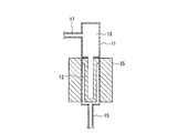
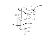
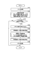
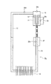
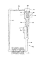
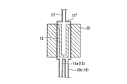
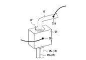
- the lineblock diagram of the information processor concerning a 1st embodiment Explanatory drawing of the evaporator in the loop type heat pipe with which the information processing apparatus which concerns on 1st Embodiment is provided. Explanatory drawing of the attachment position of the temperature sensor around an evaporator in the information processing apparatus which concerns on 1st Embodiment. Explanatory drawing of the heating apparatus attached to the steam pipe of the loop type heat pipe in the information processing apparatus which concerns on 1st Embodiment. The simplified block diagram of the information processing apparatus which concerns on 1st Embodiment. The flowchart of the process at the time of starting which the control apparatus in the information processing apparatus which concerns on 1st Embodiment performs.
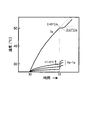
- Explanatory drawing of the change pattern of the temperature of each part of a loop type heat pipe when the heating object part of a steam pipe is heated Explanatory drawing of the state of the hydraulic fluid in a loop type heat pipe when a certain time passes after the heating start of the heating object part of a steam pipe.
- Explanatory drawing of the control content which a control apparatus performs with respect to CPU and a heating apparatus before starting completion monitoring processing The simplified block diagram of the information processing apparatus which concerns on 2nd Embodiment.
- the lineblock diagram of the information processor concerning a 3rd embodiment Explanatory drawing of the evaporator in the loop type heat pipe with which the information processing apparatus which concerns on 3rd Embodiment is provided. Explanatory drawing of the attachment position of the temperature sensor around an evaporator in the information processing apparatus which concerns on 3rd Embodiment. Explanatory drawing of the heating apparatus attached to the steam pipe of the loop type heat pipe in the information processing apparatus which concerns on 3rd Embodiment. The simplified block diagram of the information processing apparatus which concerns on 3rd Embodiment. Explanatory drawing of the control content which a control apparatus performs with respect to CPU and a heating apparatus before starting completion monitoring processing.
- Explanatory drawing of the attachment position of the temperature sensor around an evaporator in the information processing apparatus which concerns on 4th Embodiment Explanatory drawing of the apparatus which can be used as a heating apparatus.
- Explanatory drawing of an experimental result Explanatory drawing of an experimental result.
- the information processing apparatus 1 is a so-called notebook PC, the printed circuit board 30, and a loop heat pipe 10 1 and the like.
- the printed circuit board 30 is a unit in which a CPU 32 (in this embodiment, the maximum heat generation amount is 80 W) or the like is attached to the printed wiring board.
- a loop heat pipe (hereinafter referred to as LHP) 10 1 connects an evaporator 11 and a condenser 16 in a loop shape by a steam pipe 15 and a liquid pipe 17, and a predetermined amount of working fluid ( It is a heat transport device that encloses water, alternative chlorofluorocarbon, etc.).
- the evaporator 11 is a unit for vaporizing a working fluid in a liquid state (hereinafter referred to as a working fluid) existing inside the evaporator 11 with heat from the CPU 32.
- LHP10 to 1 as the evaporator 11, which is used one having a structure shown in FIG. That is, the LHP10 1, a built-in wick 12, a body portion for vaporizing the working fluid therein, the evaporator 11 and a Ekitamarishitsu 13 is for storing hydraulic fluid temporarily using It has been.
- the main body portion (FIG. 1) of the evaporator 11 is in thermal contact with the CPU 32 via a heat receiving block 25 made of a high thermal conductivity material (copper in this embodiment).
- the information processing apparatus 1 is an apparatus configured so that the evaporator 11 and the condenser 16 are substantially horizontal in a normal usage pattern (when not intentionally tilted).
- the evaporator 11 is attached with a temperature sensor 22c for measuring the temperature of the liquid storage chamber 13 (in this embodiment, a thermocouple: the same applies to other temperature sensors described later). ing. Further, a temperature sensor 22b for measuring the temperature of the main body portion of the evaporator 11 (the temperature of the CPU 32) is attached to the surface of the heat receiving block 25 on the side in contact with the CPU 32. Further, a portion of the liquid pipe 17 near the evaporator 11 (in this embodiment, a portion 30 mm away from the end of the liquid pipe 17 on the evaporator 11 side) is a temperature sensor 22d for measuring the temperature of the portion. Is attached.
- the condenser 16 (FIG. 1) is a unit for condensing the hydraulic fluid supplied by the evaporator 11 and vaporized by the evaporator 11 by heat radiation.
- the condenser 16 has a plurality of radiating fins attached to a pipe bent so as to meander (not shown; hereinafter referred to as a condenser pipe).
- the information processing apparatus 1 is provided with a cooling fan 33 for air-cooling the condenser 16.
- LHP10 1 of the information processing apparatus 1 is a device for condensing tube described above, the steam pipe 15, the length of the liquid pipe 17 has a both about 200 mm. Further, LHP10 1 as each tube, the outer diameter of 4 mm, a copper tube with an inner diameter 3mm adopted, as an evaporator 11, the size of the body portion (outer) is approximately 15 mm ⁇ 60 mm, Ekitamarishitsu 13 parts size The device adopts a device having a diameter of 15 mm ⁇ 50 mm.
- the heating device 21 includes a heater 21h (a member made of a high thermal conductivity material (a member made of copper and having a length in the length direction of the steam pipe 15 of about 50 mm in this embodiment)). It has a configuration in which a heating wire is embedded. And as shown in the figure, the temperature sensor 22a for measuring the temperature of the said part (henceforth a heating object part) is provided in the part to which the heating apparatus 21 of the steam pipe 15 is attached. It is attached.
- a control device 31 (in this embodiment, a relatively low-function microcontroller incorporating an A / D converter or the like) is provided on the printed circuit board 30 of the information processing apparatus 1 (FIG. 1).
- the control device 31 is electrically connected to the heating device 21 and the temperature sensors 22a to 22d described above.
- the printed circuit board 30 is configured (the circuit is designed) so that the control device 31 can start / stop the CPU 32.
- the temperatures measured by the temperature sensors 22a, 22b, 22c, and 22d are expressed as Ta, Tb, Tc, and Td, respectively.
- the control device 31 in the information processing apparatus 1 performs the startup process of the procedure illustrated in FIG. It is configured (programmed) to execute.
- step S101 when the information processing device 1 is activated, the control device 31 first performs a process of starting the CPU 32 (step S101).
- the processing actually performed by the control device 31 in this step S101 is a semiconductor for turning ON / OFF the power supply from the power supply device in the information processing device 1 to the main part of the printed circuit board 30 (the part excluding its own device). This is a process of controlling (turning on) the switch.
- control unit 31 based on the rate of increase of Tb (temperature of the body portion of the evaporator 11 is measured by the temperature sensor 22b), LHP10 1 state, even if the temperature of the body portion of the evaporator 11 is raised LHP10 1 within working fluid does not begin to circulate start disabled state, it performs determining state determination process which of activation state is not a start disabled state (step S102).
- the state determination process the method comprising the set time elapses, if Tb is monitored and that the above set temperature, Tb before the elapse of the set time is equal to or greater than the set temperature, LHP10 1 state Is a process of determining that the activation is impossible and ending. Furthermore, the state determination process, if Tb is set time has elapsed before the above set temperature, has a processing LHP10 1 state is completed is determined that the state can be activated.
- the time setting, the setting temperature, the state determination process of the above procedures / content, time LHP10 1 state can be determined whether a start disabled state or the state can be started, as the temperature is preset It is a value.
- Controller finished state determination processing 31 if in the state determination process is LHP10 1 state is determined that the state can be activated; (step S103 NO), in particular without performing processing, the startup process (Processing in FIG. 6) is terminated.
- step S104 the control unit 31 performs processing for stopping the operation of the CPU32 a (step S104). More specifically, in this step S104, the control device 31 performs a process for causing the CPU 32 to execute a process executed by the CPU 32 during a normal end operation.
- the control device 31 that has finished the process of step S104 starts supplying power to the heating device 21 (heater 21h) (step S105). Thereafter, the control unit 31, based on the rate of change of Ta ⁇ Td, LHP10 1 activation is completed (LHP10 1 state becomes activated state) of the monitor (wait) to start completion monitoring process (step S106) To start.
- the temperature Ta of the heating target portion increases at a speed corresponding to the heat generation amount of the heating device 21.
- the temperatures Tb to Td of the respective parts apart from the heating target part rise at a slower rate.
- Each temperature is shown in FIG. 7, by directing the condenser 16 of the information processing apparatus 1 vertically downward, forming a state in which the working fluid is present only in the condenser 16 side of LHP10 1 Then, the temperature is measured by causing the heating device 21 to actually function.
- the working fluid in the heating target portion is vaporized, the vaporized, high-temperature working fluid vapor flows to the evaporator 11 having the low temperature and is condensed and liquefied. Therefore, when Ta rises to some extent, the working fluid vapor condenses and liquefies in the evaporator 11 and in the vicinity of the evaporator 11 of the liquid pipe 17 as schematically shown in FIG.
- the state of LHP10 1 a state in which there is hydraulic fluid into the evaporator 11 (i.e., activation state) to be I can do it. Further, when the LHP10 1 state is bootable state, characteristic temperature variation (variation of temperature rate of change) in LHP10 1 of each portion occurs.
- the start completion monitoring process (FIG. 6: step S106) executed by the control device 31 is a process for monitoring such a characteristic temperature change occurring in any part where the temperature sensors 22a to 22d are attached. It is.
- the start completion monitoring process monitors for Ta that the condition that “the temperature rise per second falls by 30% or more” is satisfied, and for each of the other temperatures Tb to Td. , A process for monitoring that the condition that “a temperature change of 1 ° C. or more occurs in 5 seconds” is satisfied.
- the control device 31 after starting the CPU 32, when the LHP10 1 state is found to be a start disabled state, stops the operation of the CPU 32
- This is a device that causes the heating device 21 to function (see steps S101 to S105 in FIG. 6). That is, the control device 31 is a device that starts heating the portion to be heated of the steam pipe 15 in a state where Tb is high. Therefore, the above-mentioned conditions are not obtained from the temperature measurement results shown in FIG. 7, but “obtained by stopping the operation of the CPU 32 and causing the heating device 21 to function after raising Tb to the set temperature. It is determined from “Measurement results of Ta to Td”.
- the control device 31 that has finished the startup completion monitoring process (FIG. 6: step S106) stops the power supply to the heating device 21 (step S107), and then starts (restarts) the CPU 32 (step S108). And the control apparatus 31 complete
- control device 31 when operating the heating device 21 for LHP10 1 activation in the inactivatable state, the evaporation of the liquid pipe 17 based on the temperature change pattern portion or the like of the vessel 11 near to monitor the LHP10 1 state is bootable state, when the LHP10 1 state becomes activated state, stops the operation of the heating device 21 It is a device.
- the information processing apparatus 1, the LHP10 1 in the start disabled state efficiently (that such energy than necessary to heat the steam pipe 15 is consumed or, delayed unnecessarily start timing of CPU32 This is a device that can be activated.
- Second Embodiment >> Hereinafter, the configuration and operation of the information processing apparatus 1 according to the second embodiment will be described focusing on differences from the information processing apparatus 1 according to the first embodiment.
- the information processing apparatus 1 includes an LHP (loop heat pipe) 10 2 for cooling the CPU 32, a heating device 21, a control device 31, and the like. Device.
- LHP loop heat pipe
- This information processing apparatus 1 (hereinafter also referred to as the second information processing apparatus 1) is a so-called information processing apparatus 1 according to the first embodiment (hereinafter also referred to as the first information processing apparatus 1). It is a notebook PC.
- LHP10 2 is the evaporator 11 shown in FIG. 11 (and 10 '), i.e., the evaporator 11 without a Ekitamarishitsu 13' is a LHP equipped with.
- the second information processing apparatus 1 is an apparatus configured without attaching an evaporator 11 ′ equivalent to the temperature sensor 22c (see FIG. 3), as well as a start completion monitoring process.
- a device different from the above-described control device 31 only in that the change pattern of Tc is not sometimes monitored is mounted on the printed wiring board 30 as the control device 31.
- the second information processing apparatus 1 changes the evaporator 11 in the first information processing apparatus 1 to the evaporator 11 ′, and removes the configuration and functions that are unnecessary due to the change from the first information processing apparatus 1. It has a configuration.
- the information processing apparatus 1 Even if Tc is not known, if Ta or the like is known, it can be detected that the state of LHP 10 2 has become a startable state. Accordingly, the information processing apparatus 1 according to the second embodiment also, the LHP10 2 in the start disabled state efficiently activated can can be said to be a device.
- the third information processing apparatus 1 is also a so-called notebook PC, and a printed circuit board 30, LHP10 3 like.
- the LHP 10 3 connects the evaporator 11 and the condenser 16 in a loop with a steam pipe 15 and a liquid pipe 17, and a predetermined amount of working fluid is placed inside them. Is a heat transport device encapsulating
- the evaporator 11 and the liquid pipe 17 of the LHP 10 3 are the same as the evaporator 11 and the liquid pipe 17 of the LHP 10 1 , respectively.
- the steam pipe 15 of the LHP 10 3 is a manifold consisting of a main pipe 15c, and two branch pipes 15a and 15b branched from the main pipe 15c.
- the steam pipe 15 is manufactured by adopting a copper pipe having an outer diameter of 4 mm and an inner diameter of 3 mm as each pipe.
- the evaporator 11 of the LHP 10 3 is essentially the same as the evaporator 11 of the LHP 10 1 . However, the evaporator 11 (see FIGS. 13 to 15) of the LHP 10 3 is connected to the branch pipe 15a and the branch pipe 15b of the steam pipe 15 (there are two places where the steam pipe 15 is connected). ing.
- the LHP 10 3 evaporator 11 (FIG. 13) is located on the CPU 32 on the printed circuit board 30.
- the main body portion of the evaporator 11 is accommodated in a heat receiving block 25 made of a high thermal conductivity material (copper in this embodiment), and the heat receiving block 25 is fixed to the upper surface of the CPU 32.
- the evaporator 11 is provided with a temperature sensor 22c for measuring the temperature of the liquid storage chamber 13. Further, a temperature sensor 22b for measuring the temperature of the main body portion of the evaporator 11 (the temperature of the CPU 32) is attached to the surface of the heat receiving block 25 on the side in contact with the CPU 32. Further, a portion of the liquid pipe 17 near the evaporator 11 (in this embodiment, a portion 30 mm away from the end of the liquid pipe 17 on the evaporator 11 side) is a temperature sensor 22d for measuring the temperature of the portion. Is attached.
- a heating device 21 is attached to the branch pipe 15a (FIG. 13) of the steam pipe 15.
- the heating device 21 includes a heater 21 h on a member made of a high thermal conductivity material (in this embodiment, a member made of copper and having a length in the length direction of the steam pipe 15 of about 50 mm). It has an embedded configuration.
- the temperature sensor 22a for measuring the temperature of the said part is provided in the part to which the heating apparatus 21 of the steam pipe 15 is attached. It is attached.
- the heating device 21 is attached to the branch pipe 15a so that the surface on the evaporator 11 side substantially coincides with the liquid level position.
- the printed circuit board 30 included in the third information processing apparatus 1 is the same as the printed circuit board 30 included in the first information processing apparatus 1.
- a control device 31 that is electrically connected to the heating device 21 and the temperature sensors 22a to 22d is provided on the printed circuit board 30 included in the third information processing apparatus 1 (see FIGS. 13 and 17). Then, when the third information processing apparatus 1 is activated, the control device 31 executes the activation process (see FIG. 6) having the contents already described. Therefore, when the LHP 10 3 is in a non-startable state when the third information processing apparatus 1 is started, the control device 31 temporarily stops the operation of the CPU 32 as schematically shown in FIG. Power supply to the heating device 21 is started.
- the power supply to the heating device 21 When the power supply to the heating device 21 is started, as in the first information processing device 1 (see FIG. 9), after a while, it operates in the evaporator 11 and in the portion near the evaporator 11 of the liquid pipe 17.
- the liquid vapor is condensed and liquefied.
- the temperatures Tb to Td of the portions where the working fluid vapor is condensed and liquefied increase by about 1 to 5 ° C. due to the release of heat during condensation.
- the control device 31 stops the power supply to the heating device 21 and restarts the CPU 32 when such a temperature change occurs. It has a function (see FIG. 6).
- the third information processing apparatus 1 also efficiently uses the LHP 10 3 that is in a non-startable state (e.g., energy more than necessary for heating the steam pipe 15 is consumed or the start time of the CPU 32 is more than necessary. It is a device that can be started up in a manner that does not cause delays.
- a non-startable state e.g., energy more than necessary for heating the steam pipe 15 is consumed or the start time of the CPU 32 is more than necessary. It is a device that can be started up in a manner that does not cause delays.
- the third information processing apparatus 1 is also an apparatus that can start the LHP 10 3 that is in the unbootable state earlier (in a shorter time) than the first information processing apparatus 1.
- LHP10 1 of the evaporator 11 while the condenser 16 is connected by one of the steam pipe 15. Therefore, when the heating of LHP10 1 steam pipe 15, as schematically shown in FIG. 19, generated in the heat target portion, working fluid steam temperature is high (open arrow), from the evaporator 11 side Since it is obstructed by the flow of the low-temperature working fluid vapor (black arrow), it does not flow smoothly to the vicinity of the wick 12 of the evaporation section 11.
- the evaporator 11 and the condenser 16 of the LHP 10 3 are connected by a branch pipe 15 a that is heated by the heating device 21 and a branch pipe 15 b that is not heated by the heating device 21. Therefore, when the steam pipe 15 (branch pipe 15a) of the LHP 10 3 is heated, the hydraulic fluid vapor having a high temperature generated in the heating target portion evaporates through the branch pipe 15a as schematically shown in FIG. The low-temperature working fluid vapor from the evaporator 11 side flows to the condenser 11 side through the branch pipe 15b.
- the third information processing apparatus 1 is an apparatus that can start LHP 10 3 (10 1 ) earlier than the first information processing apparatus 1.
- the evaporator 11 was completely dried out from the start-up experiment (power supplied to the heating device 21: 10 W) of the first and third information processing apparatuses 1 with the condenser 16 oriented vertically downward. It has been confirmed that the time required for starting the LHP 10 1 is about 30 seconds, and the time required for starting the LHP 10 3 with the evaporator 11 completely dried out is about 10 seconds. Therefore, it can be said that the above configuration adopted in the third information processing apparatus 1 is extremely effective in shortening the LHP activation time.
- the steam pipe 15 of the LHP 10 3 has a portion having a larger flow path cross-sectional area than the steam pipe 15 of the LHP 10 1 .
- the LHP 10 3 has a configuration in which the working fluid vapor from the evaporator 11 easily flows, as schematically shown in FIG. Accordingly, the LHP 10 3 has a higher operational stability after startup.
- the fourth information processing apparatus 1 is an apparatus including an LHP 10 4 for cooling the CPU 32, a heating device 21, a control device 31, and the like.
- the fourth information processing apparatus 1 is also a so-called notebook PC, like the first to third information processing apparatuses 1 described above.
- the LHP 10 4 included in the fourth information processing apparatus 1 corresponds to the LHP 10 3 in which the evaporator 11 is changed to the evaporator 11 ′, as is apparent from a comparison between FIG. 22 and FIG.
- LHP10 4 evaporator 11 used in 'is, LHP10 evaporator 11 2 are used' (FIG. 10, see FIG. 11) is the same as in the nature. However, as shown in FIG. 23 (and FIG. 22), the evaporator 11 ′ of the LHP 10 4 is connected to the branch pipe 15a and the branch pipe 15b of the steam pipe 15 (the connection point with the steam pipe 15 is There are two places).
- the fourth information processing apparatus 1 is an apparatus in which an evaporator 11 ′ is not attached with a temperature sensor 22c (see FIG. 3), and the second information processing apparatus. 1 is a device in which a device having the same function as the control device 31 in 1 is mounted on the printed wiring board 30 as the control device 31.
- the fourth information processing apparatus 1 changes the evaporator 11 in the third information processing apparatus 1 to the evaporator 11 ′, and removes the configuration and functions that are unnecessary due to the change from the third information processing apparatus 1. It has a configuration.
- the information processing apparatus 1 Even if Tc is not known, if Ta or the like is known, it can be detected that the state of LHP 10 4 has become a startable state. Accordingly, the information processing apparatus 1 according to the fourth embodiment also, the LHP10 2 in the start disabled state efficiently activated can can be said to be a device.
- the information processing apparatus 1 according to each of the above-described embodiments can perform various modifications.
- the information processing apparatus 1 according to each embodiment can be transformed into a tower-type PC in which the evaporator 11 (11 ′) is located above the condenser 16.
- the control device 31 can be configured to execute “a start-up process for causing the heating device 21 to function before the CPU 32 is started”.
- a Peltier element can be used instead of the heating device 21 (FIG. 4) incorporating the heater 21h.
- the shape of the steam pipe 15 and the liquid pipe 17 is devised to heat the portion to be heated of the steam pipe 15 and the liquid pipe 17 with one Peltier element.
- the portion near the evaporator 11 (11 ′) can be cooled.
- a highly heat conductive member 43 is provided at the heating target portion of the steam pipe 15 and heat transfer from the heat receiving block 25 to the member 43 is performed. It is also possible to provide a heat medium circulation channel 42 equipped with a pump 41 for carrying out.
- an LHP having a size slightly larger than that described above was attached with eight temperature sensors 22a to 22h, and the results shown in FIGS. 26A and 26B were obtained. Is obtained.
- Ta to Te are temperatures measured by the temperature sensors 22a to 22h.
- each temperature sensor 22x The temperature of each part of the LHP 10 (LHP 10 1 to LHP 10 4 ) measured by each temperature sensor 22x only needs to correspond to the temperature of the working fluid in each part. Therefore, it is not necessary to attach each temperature sensor 22x to a pipe wall (see FIG. 3 etc.), etc., and each temperature sensor 22x (the part of the temperature sensor 22x that actually measures the temperature; Can also be placed in the tube.
- the information processing apparatus 1 according to each embodiment has a plurality of temperature sensors 22x attached to the LHP 10, the state of the LHP 10 can be activated only from the temperature measurement result by one temperature sensor 22x. It can be determined whether or not. Therefore, the information processing apparatus 1 according to each embodiment can be modified to one in which only one temperature sensor 22x is attached to the LHP 10.
- the temperature change amount (change amount of the temperature change rate) resulting from the condensation of the working fluid vapor becomes smaller in the order of Ta, Tb, Tc, and Td (see FIG. 7). Therefore, when only one temperature sensor 22x is attached to the LHP 10, it is desirable to attach only the temperature sensor 22a for measuring the temperature of the portion to be heated.
- the above-described start completion monitoring process is a process for determining whether or not the LHP 10 is in a startable state based on the changing speed of Ta to Td. Can correspond to the contents of the actual temperature change caused by the condensation of the working fluid vapor.
- Ta, Tb, Tc, and Td are as shown in FIG. It may change.
- the start completion monitoring process is performed.
- Ta is periodically measured and its maximum value is managed, and the current measurement result is managed.
- the maximum value ⁇ for example, 3 ° C.
- a startup completion monitoring process of determining whether or not the state of the LHP 10 has become a startable state based on the changing speed of Ta to Td should be adopted. I can do it.
- the start completion monitoring process is performed at a temperature at which Ta is sure that the working fluid vapor is condensed and liquefied (for example, 50 ° C. ; See FIG. 7), the processing of determining that the state of the LHP 10 has become a startable state can also be made.
- Each LHP 10 is provided with several evaporators 11 (11 ′) in parallel with the evaporators 11 (11 ′) (a plurality of evaporators 11 (11 between the steam pipe 15 and the liquid pipe 17). ′) Can be transformed into a parallel connection). Further, the LHPs 10 2 and 10 4 can be modified into those using the steam pipes 15 having three or more branch pipes. Furthermore, the information processing apparatus 1 (notebook PC) detects whether or not there is working fluid in the evaporator 11 by detecting the attitude of the apparatus while the LHP 10 is stopped by using an accelerometer (a steam pipe at startup). It is also possible to change to a device that manages whether or not 15 heating is necessary.
- the disclosed technology can be used in various fields that require cooling.
Landscapes
- Engineering & Computer Science (AREA)
- Life Sciences & Earth Sciences (AREA)
- Sustainable Development (AREA)
- Physics & Mathematics (AREA)
- Thermal Sciences (AREA)
- Mechanical Engineering (AREA)
- General Engineering & Computer Science (AREA)
- Cooling Or The Like Of Semiconductors Or Solid State Devices (AREA)
Abstract
蒸発器の温度上昇では起動しない状態にあるループ型ヒートパイプを、効率的に起動できるループ型ヒートパイプシステム。ループ型ヒートパイプシステムは、CPU32等を冷却するためのループ型ヒートパイプ101、そのの蒸気管15に設けられた加熱装置21、及び、蒸発器11の温度上昇では起動しない状態にあるループ型ヒートパイプ101を起動するために加熱装置21を動作させ、その後、ループ型ヒートパイプ101の液管17の蒸発器11近傍の部分等で作動流体の凝縮液化に起因する温度変化が生じたときに加熱装置21の動作を停止させる制御装置31を備える。
Description
本発明は、ループ型ヒートパイプシステムと、ループ型ヒートパイプを備えた情報処理装置とに関する。
各種発熱体を冷却するためのデバイスとして、作動液(液体状態にある作動流体)を発熱体からの熱で気化させるための蒸発器と、気化した作動液を放熱により凝縮させるための凝縮器とを、蒸気管及び液管によりループ状に接続したループ型ヒートパイプが知られている。
このループ型ヒートパイプは、その動作原理上、蒸発器内に作動液が存在していないと、発熱体の温度上昇により蒸発器の温度が上昇しても起動しない(熱輸送デバイスとしての動作を開始しない/内部の作動流体が循環し始めない)デバイスとなっている。従って、ループ型ヒートパイプは、通常、蒸発器の高さ(鉛直方向位置)が凝縮器よりも低くなるように構成されている(組込対象に組み込まれている)。しかしながら、ループ型ヒートパイプの組込対象によっては、蒸発器の高さを凝縮器よりも高くせざるを得ない場合もある。
そのため、蒸発器の高さが凝縮器よりも低いループ型ヒートパイプを起動できるようにするために、その蒸気管の一部(凝縮器近傍の部分)にヒーターを設け、発熱体(冷却対象)の始動前に、所定時間の間だけ、蒸気管の一部をヒーターで加熱することが提案されている。
発熱体の始動前(ループ型ヒートパイプを起動する必要が生じた時)に、蒸気管の一部が加熱されるようにしておけば、蒸発器内に作動液が存在していない状態にあるループ型ヒートパイプを起動することができる。
ただし、ループ型ヒートパイプ内の作動液の分布は、蒸発器、凝縮器の位置関係が変わらないものであっても、冷却対象を停止させた後の経過時間に応じて変化する。また、可搬型の情報処理装置(ノートPC(Personal Computer)等)に組み込まれたループ型ヒートパイプ内の作動液の分布は、運搬時/未使用時の姿勢によっても変化する。そして、ループ型ヒートパイプ内の作動液の分布によっては、蒸気管の短時間の加熱でループ型ヒートパイプを起動することが出来る場合がある。従って、蒸気管の加熱時間を固定しておいたのでは、蒸気管の加熱に必要以上のエネルギーが消費されてしまう、冷却対象の起動時期が必要以上に遅れる、といった問題が生じてしまうことになる。
そこで、開示の技術の課題は、蒸発器の温度上昇では起動しない状態にあるループ型ヒートパイプを効率的に起動できるループ型ヒートパイプシステム及び情報処理装置を提供することにある。
上記課題を解決するために、開示の技術の一態様のループ型ヒートパイプシステムは、液体状態にある作動流体を発熱体からの熱で気化させる蒸発器と、気体状態にある作動流体を放熱により凝縮させる凝縮器とを、蒸発器からの作動流体を凝縮器に供給する蒸気管及び凝縮器からの作動流体を蒸発器に供給する液管によりループ状に接続したループ型ヒートパイプと、ループ型ヒートパイプが熱輸送デバイスとして動作している状況下と、ループ型ヒートパイプが熱輸送デバイスとして動作しておらず,且つ,蒸発器内に液体状態にある作動流体が存在していない状況下とで、その内部の作動流体の相状態が異なる,ループ型ヒートパイプの部分の温度を測定する温度センサと、蒸気管の一部である加熱対象部分を加熱する加熱装置と、蒸発器の温度上昇では熱輸送デバイスとしての動作を開始しない状態にあるループ型ヒートパイプに熱輸送デバイスとしての動作を開始させるために、加熱装置を制御する制御装置であって、加熱装置に加熱対象部分を加熱させている間、温度センサを利用してループ型ヒートパイプの上記部分の温度を監視し、当該温度に、ループ型ヒートパイプ内での作動流体の凝縮液化に起因する変化が生じたときに、加熱装置の加熱動作を停止させる制御装置とを備える。
また、上記課題を解決するために、開示の技術の他の態様のループ型ヒートパイプシステムは、液体状態にある作動流体を発熱体からの熱で気化させる蒸発器と、気体状態にある作動流体を放熱により凝縮させる凝縮器と、凝縮器からの作動流体を蒸発器に供給する液管と、本管及び本管から枝分かれした複数の枝管を有し,各枝管の開口端が蒸発器に接続され,本管の開口端が凝縮器と接続された蒸気管とを含むループ型ヒートパイプと、ループ型ヒートパイプの複数の枝管の中の一部の枝管を加熱する加熱装置とを備える。
また、上記課題を解決するために、開示の技術の一態様の情報処理装置は、動作時に冷却すべき電子部品と、液体状態にある作動流体を電子部品からの熱で気化させる蒸発器と、気体状態にある作動流体を放熱により凝縮させる凝縮器とを、蒸発器からの作動流体を凝縮器に導入する蒸気管及び凝縮器からの作動流体を蒸発器に導入する液管によりループ状に接続したループ型ヒートパイプと、ループ型ヒートパイプが熱輸送デバイスとして動作している状況下と、ループ型ヒートパイプが熱輸送デバイスとして動作しておらず,且つ,蒸発器内に液体状の作動流体が存在していない状況下とで、その内部の作動流体の相状態が異なる,ループ型ヒートパイプの部分の温度を測定する温度センサと、蒸気管の一部である加熱対象部分を加熱する加熱装置と、蒸発器の温度上昇では熱輸送デバイスとしての動作を開始しない状態にあるループ型ヒートパイプに熱輸送デバイスとしての動作を開始させるために、加熱装置を制御する制御装置であって、加熱装置に加熱対象部分を加熱させている間、温度センサを利用してループ型ヒートパイプの上記部分の温度を監視し、当該温度に、ループ型ヒートパイプ内での作動流体の凝縮液化に起因する変化が生じたときに、加熱装置の加熱動作を停止させる制御装置とを備える。
上記構成を採用しておけば、蒸発器内の作動液が存在していない状態にあるループ型ヒートパイプを効率的に起動できるループ型ヒートパイプシステム及び情報処理装置を実現することが出来る。
以下、発明者らが開発した4タイプの情報処理装置(以下、第1~第4実施形態に係る情報処理装置と表記する)を、図面を参照して詳細に説明する。
《第1実施形態》
まず、図1乃至図4を用いて、第1実施形態に係る情報処理装置1の構成を説明する。
まず、図1乃至図4を用いて、第1実施形態に係る情報処理装置1の構成を説明する。
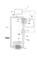
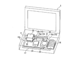
図1に模式的に示してあるように、第1実施形態に係る情報処理装置1は、いわゆるノートPCであり、プリント回路板30、ループ型ヒートパイプ101等を備えている。
プリント回路板30は、CPU32(本実施形態では、最大発熱量が80Wのもの)等を、プリント配線板に取り付けたユニットである。
ループ型ヒートパイプ(以下、LHPと表記する)101は、蒸発器11と凝縮器16とを、蒸気管15及び液管17によってループ状に接続し、それらの内部に所定量の作動流体(水、代替フロン等)を封入した熱輸送デバイスである。
蒸発器11は、その内部に存在する,液体状態にある作動流体(以下、作動液と表記する)を、CPU32からの熱で気化させるためのユニットである。
LHP101には、この蒸発器11として、図2に示した構成を有するものが用いられている。すなわち、LHP101には、ウィック12を内蔵した,作動液をその内部で気化させるための本体部分と、作動液を一時的に溜めておくための液溜室13とを有する蒸発器11が用いられている。
蒸発器11の本体部分(図1)は、高熱伝導性材料(本実施形態では、銅)からなる受熱ブロック25を介してCPU32と熱的に接触している。そして、情報処理装置1は、通常の使用形態では(意図的に傾けない場合には)、蒸発器11と凝縮器16とがほぼ水平となるように構成された装置となっている。
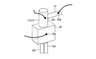
図3に示したように、蒸発器11には、液溜室13の温度を測定するための温度センサ22c(本実施形態では、熱電対:後述する他の各温度センサも同様)が取り付けられている。また、受熱ブロック25の,CPU32と接する側の面には、蒸発器11の本体部分の温度(CPU32の温度)を測定するための温度センサ22bが取り付けられている。さらに、液管17の,蒸発器11近傍の部分(本実施形態では、液管17の蒸発器11側の端から30mm離れた部分)には、当該部分の温度を測定するための温度センサ22dが取り付けられている。
凝縮器16(図1)は、蒸気管15を介して供給される,蒸発器11により気化された作動液を、放熱により、凝縮させるためのユニットである。この凝縮器16は、蛇行するように曲げた管(図示略;以下、凝縮管と表記する)に複数の放熱フィンを取り付けたものとなっている。情報処理装置1には、この凝縮器16を空冷するための冷却用ファン33が設けられている。
なお、本情報処理装置1が備えるLHP101は、上記した凝縮管、蒸気管15、液管17の長さがいずれもおよそ200mmとなっているデバイスである。また、LHP101は、各管として、外径4mm、内径3mmの銅管を採用し、蒸発器11として、本体部分のサイズ(外形)がおよそφ15mm×60mmであり、液溜室13部分のサイズがφ15mm×50mmであるものを採用したデバイスとなっている。
LHP101の蒸気管15の途中(詳細は後述)には、蒸気管15を加熱するための加熱装置21が取り付けられている。この加熱装置21は、図4に示したように、高熱伝導性材料製の部材(本実施形態では、銅製の,蒸気管15の長さ方向の長さがおよそ50mmの部材)にヒーター21h(発熱用電線)を埋め込んだ構成を有している。そして、同図に示してあるように、蒸気管15の加熱装置21が取り付けられている部分には、当該部分(以下、加熱対象部分と表記する)の温度を測定するための温度センサ22aが取り付けられている。
情報処理装置1(図1)のプリント回路板30上には、制御装置31(本実施形態では、A/D変換器等を内蔵した、比較的に低機能のマイクロコントローラ)が設けられている。この制御装置31は、上記した加熱装置21及び温度センサ22a~22dと電気的に接続されている。そして、プリント回路板30は、制御装置31が、CPU32を始動/停止させることが出来るように構成された(回路設計がなされた)ものとなっている。
以上のことを前提に、以下、第1実施形態に係る情報処理装置1の構成及び動作をさらに具体的に説明する。なお、以下の説明では、温度センサ22a、22b、22c、22dによって測定される温度のことを、それぞれ、Ta、Tb、Tc、Tdと表記する。
加熱装置21(図4参照)の蒸気管15への取り付け位置は、凝縮器16を鉛直下方向に向けることにより全作動液をLHP101内の凝縮器16側に集めた場合に、図5に模式的に示した状態が形成されることになるように、定められている。すなわち、情報処理装置1は、加熱装置21を、その蒸発器11側の面位置が、全作動液をLHP101内の凝縮器16側に集めた場合における蒸気管15内の作動液の液面位置とほぼ一致するように、蒸気管15に取り付けたものとなっている。
そして、情報処理装置1内の制御装置31は、情報処理装置1が起動される(情報処理装置1の図示せぬ電源スイッチが投入される)と、図6に示した手順の起動時処理を実行するように、構成(プログラミング)されている。
すなわち、情報処理装置1が起動されると、制御装置31は、まず、CPU32を始動する処理(ステップS101)を行う。このステップS101で制御装置31が実際に行う処理は、情報処理装置1内の電源装置からプリント回路板30の主要部分(自装置を除いた部分)への電力供給をON/OFFするための半導体スイッチを制御する(オンにする)処理である。
次いで、制御装置31は、Tb(温度センサ22bによって測定される蒸発器11の本体部分の温度)の上昇速度に基づき、LHP101の状態が、蒸発器11の本体部分の温度が上昇してもLHP101内で作動流体が循環し始めない起動不可状態、起動不可状態ではない起動可能状態のいずれであるかを判定する状態判定処理(ステップS102)を行う。
この状態判定処理は、設定時間が経過することと、Tbが設定温度以上となることとを監視し、設定時間が経過する前にTbが設定温度以上となった場合には、LHP101の状態が起動不可状態であると判定して終了する処理である。また、状態判定処理は、Tbが設定温度以上となる前に設定時間が経過した場合には、LHP101の状態が起動可能状態であると判定して終了する処理となっている。なお、設定時間、設定温度とは、上記手順/内容の状態判定処理により、LHP101の状態が起動可能状態であるか起動不可状態であるかを判定できる時間、温度として、予め設定されている値のことである。本実施形態に係る情報処理装置1は、これらの値を、『LHP101の状態が、蒸発器11内に作動液が存在していない状態となっている情報処理装置1』(起動時処理が行われないもの)についてのTbの変化パターンの測定結果と、『LHP101の状態が、蒸発器11内に作動液が存在している状態となっている情報処理装置1』についてのTbの変化パターンの測定結果とから、決定したものとなっている。
状態判定処理を終えた制御装置31は、状態判定処理にてLHP101の状態が起動可能状態であると判定した場合(ステップS103;NO)には、特に処理を行うことなく、この起動時処理(図6の処理)を終了する。
一方、状態判定処理にてLHP101の状態が起動不可状態であると判定した場合(ステップS103;YES)、制御装置31は、CPU32の動作を停止させるための処理(ステップS104)を行う。より具体的には、このステップS104にて、制御装置31は、通常の終了操作時にCPU32が実行する処理をCPU32に実行させるための処理を行う。
ステップS104の処理を終えた制御装置31は、加熱装置21(ヒーター21h)への電力供給を開始する(ステップS105)。その後、制御装置31は、Ta~Tdの変化速度に基づき、LHP101の起動が完了する(LHP101の状態が起動可能状態となる)のを監視(待機)する起動完了監視処理(ステップS106)を開始する。
この起動完了監視処理の詳細を説明する前に、図7及び図8を用いて、起動不可状態にあるLHP101の蒸気管15の加熱対象部分を加熱した場合に生ずる現象を説明しておくことにする。
作動液がLHP101内の凝縮器16側にのみ存在している状況下(図5参照)、時間t0に、CPU32を機能させることなく、蒸気管15の加熱対象部分の加熱を開始した場合を考える。
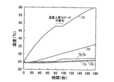
この場合、図7に示したように、加熱対象部分の温度Taは、加熱装置21の発熱量に応じた速度で上昇することになる。また、加熱対象部分から離れた各部の温度Tb~Tdは、より遅い速度で上昇することになる。なお、この図7に示してある各温度は、情報処理装置1の凝縮器16を鉛直下方向に向けることにより、作動液がLHP101内の凝縮器16側にのみ存在している状態を形成した後、加熱装置21を実際に機能させることにより測定した温度である。
加熱対象部分の温度Taが上昇すると、加熱対象部分内の作動液が気化することにより、加熱対象部分内の圧力が上昇する。そのため、LHP101内の,加熱対象部分とは異なる部分(作動液蒸気が存在している各部分)の圧力も上昇し、その結果として、温度が比較的に低い部分で作動液蒸気が凝縮液化することになる。
また、加熱対象部分内の作動液が気化すると、気化した,温度の高い作動液蒸気が、温度の低い蒸発器11側に流れて、凝縮液化することにもなる。従って、Taが或る程度上昇すると、図8に模式的に示したように、蒸発器11内や、液管17の蒸発器11近傍の部分で、作動液蒸気が凝縮液化する。
そして、作動液蒸気の凝縮液化時には、熱が放出されるので、作動液蒸気が或る時間t1に凝縮液化した場合、図7に示してあるように、作動液蒸気が凝縮液化した各部分の温度Tb~Tdが、凝縮液化時の熱量放出により1~5℃程度上昇することになる。
また、作動液蒸気が凝縮液化すると、各部の内圧が急激に減少する。そのため(PV=nRTにより圧力が下がると温度が下がるため)、加熱対象部分の温度Taの上昇速度が低下する(情報処理装置1では、0.45℃/sec→0.07℃/sec)ことにもなる。
このように、起動不可状態にあるLHP101の蒸気管15の加熱対象部分を加熱すると、LHP101の状態を、蒸発器11内に作動液が存在する状態(つまり、起動可能状態)とすることが出来る。また、LHP101の状態が起動可能状態となる際には、LHP101の各部で特徴的な温度変化(温度の変化速度の変化)が生ずる。
制御装置31が実行する起動完了監視処理(図6:ステップS106)は、そのような特徴的な温度変化が、温度センサ22a~22dが取り付けられているいずれかの部分で生ずるのを監視する処理である。
より具体的には、起動完了監視処理は、Taについては、『1秒あたりの温度上昇幅が30%以上低下する』という条件が満たされるのを監視し、他の各温度Tb~Tdについては、『5秒間の間に1℃以上の温度変化が生ずる』という条件が満たされるのを監視する処理となっている。
なお、制御装置31は、図9に模式的に示したように、CPU32を起動した後、LHP101の状態が起動不可状態となっていることが分かったときに、CPU32の動作を停止させて加熱装置21を機能させる装置(図6のステップS101~S105参照)である。すなわち、制御装置31は、Tbが高い状態で、蒸気管15の加熱対象部分の加熱を開始する装置となっている。そのため、上記した各条件は、図7に示した温度の測定結果からではなく、『Tbを設定温度まで上昇させた後、CPU32の動作を停止させると共に加熱装置21を機能させることにより得られたTa~Tdの測定結果』から定めたものとなっている。
起動完了監視処理(図6:ステップS106)を終えた制御装置31は、加熱装置21への電力供給を停止(ステップS107)してから、CPU32を始動(再始動)する(ステップS108)。そして、制御装置31は、この起動時処理を終了する。
以上の説明から明らかなように、本実施形態に係る情報処理装置1(制御装置31)は、起動不可状態にあるLHP101の起動のために加熱装置21を動作させる場合、液管17の蒸発器11近傍の部分等の温度変化パターンに基づき、LHP101の状態が起動可能状態になるのを監視し、LHP101の状態が起動可能状態になったときに、加熱装置21の動作を停止させる装置となっている。
従って、この情報処理装置1は、起動不可状態にあるLHP101を、効率的に(蒸気管15の加熱に必要以上のエネルギーが消費されてしまうといったことや、CPU32の起動時期が必要以上に遅れるといったことが生じない形で)、起動できる装置となっていることになる。
《第2実施形態》
以下、第1実施形態に係る情報処理装置1と異なっている点を中心に、第2実施形態に係る情報処理装置1の構成、動作を説明する。
以下、第1実施形態に係る情報処理装置1と異なっている点を中心に、第2実施形態に係る情報処理装置1の構成、動作を説明する。
図10に模式的に示してあるように、第2実施形態に係る情報処理装置1は、CPU32を冷却するためのLHP(ループ型ヒートパイプ)102、加熱装置21、制御装置31等を備えた装置である。
この情報処理装置1(以下、第2情報処理装置1とも表記する)は、上記した第1実施形態に係る情報処理装置1(以下、第1情報処理装置1とも表記する)と同様に、いわゆるノートPCである。
LHP102は、図11(及び図10)に示した蒸発器11′、すなわち、液溜室13を有さない蒸発器11′を備えたLHPである。
そして、第2情報処理装置1は、図12に示したように、蒸発器11′に、温度センサ22c(図3参照)相当のものを取り付けずに構成した装置であると共に、起動完了監視処理時にTcの変化パターンを監視しない点のみが上記した制御装置31と異なる装置を、制御装置31として、プリント配線板30上に実装した装置となっている。
要するに、第2情報処理装置1は、第1情報処理装置1内の蒸発器11を蒸発器11′に変更すると共に、その変更により不要となった構成及び機能を第1情報処理装置1から取り除いた構成を有している。
そして、Tcが分からなくても、Ta等が分かれば、LHP102の状態が起動可能状態になったことを検出できる。従って、この第2実施形態に係る情報処理装置1も、起動不可状態にあるLHP102を効率的に起動できる装置となっていると言うことが出来る。
《第3実施形態》
以下、図13乃至図21を用いて、第3実施形態に係る情報処理装置1(以下、第3情報処理装置1とも表記する)の構成及び動作を、説明する。
以下、図13乃至図21を用いて、第3実施形態に係る情報処理装置1(以下、第3情報処理装置1とも表記する)の構成及び動作を、説明する。
図13に模式的に示してあるように、第3情報処理装置1も、いわゆるノートPCであり、プリント回路板30、LHP103等を備えている。
LHP103は、LHP101(図1、図5参照)と同様に、蒸発器11と凝縮器16とを蒸気管15及び液管17によってループ状に接続し、それらの内部に所定量の作動流体を封入した熱輸送デバイスである。
このLHP103の蒸発器11、液管17は、それぞれ、LHP101の蒸発器11、液管17と同じものである。LHP103の蒸気管15は、本管15cと、本管15cから枝分かれした2本の枝管15a及び枝管15bとからなる多岐管である。この蒸気管15は、各管として、外径4mm、内径3mmの銅管を採用して製造したものとなっている。
LHP103の蒸発器11は、LHP101の蒸発器11と本質的には同じものである。ただし、LHP103の蒸発器11(図13~図15参照)は、蒸気管15の枝管15a及び枝管15bに接続されたもの(蒸気管15との接続箇所が2箇所あるもの)となっている。
LHP103の蒸発器11(図13)は、プリント回路板30上のCPU32上に位置している。蒸発器11の本体部分は、高熱伝導性材料(本実施形態では、銅)からなる受熱ブロック25に収容されており、受熱ブロック25は、CPU32の上面に固定されている。
図15に示してあるように、蒸発器11には、液溜室13の温度を測定するための温度センサ22cが取り付けられている。また、受熱ブロック25の,CPU32と接する側の面には、蒸発器11の本体部分の温度(CPU32の温度)を測定するための温度センサ22bが取り付けられている。さらに、液管17の,蒸発器11近傍の部分(本実施形態では、液管17の蒸発器11側の端から30mm離れた部分)には、当該部分の温度を測定するための温度センサ22dが取り付けられている。
蒸気管15の枝管15a(図13)には、加熱装置21が取り付けられている。この加熱装置21は、図16に示したように、高熱伝導性材料製の部材(本実施形態では、銅製の,蒸気管15の長さ方向の長さがおよそ50mmの部材)にヒーター21hを埋め込んだ構成を有している。そして、同図に示してあるように、蒸気管15の加熱装置21が取り付けられている部分には、当該部分(以下、加熱対象部分と表記する)の温度を測定するための温度センサ22aが取り付けられている。
蒸気管15の形状は、第3情報処理装置1の凝縮器16側を鉛直下方向に向けることにより全作動液をLHP103内の凝縮器16側に集めた場合に、図17に示した状態が形成されることになるように、定められている。すなわち、蒸気管15の形状は、凝縮器16側を鉛直下方向に向けることにより全作動液を凝縮器16側に集めた場合における作動液の液面位置が、蒸気管15の分岐部よりも高くなるように、定められている。
そして、加熱装置21は、蒸発器11側の面が、上記液面位置とほぼ一致するように、枝管15aに対して取り付けられている。
第3情報処理装置1が備えるプリント回路板30は、第1情報処理装置1が備えるプリント回路板30と同じものである。
すなわち、第3情報処理装置1が備えるプリント回路板30上には(図13、図17参照)、加熱装置21及び温度センサ22a~22dと電気的に接続された制御装置31が設けられている。そして、この制御装置31は、第3情報処理装置1が起動されると、既に説明した内容の起動時処理(図6参照)を実行する。従って、制御装置31は、第3情報処理装置1の起動時にLHP103が起動不可状態にあった場合には、図18に模式的に示したように、CPU32の動作を一旦停止させてから、加熱装置21への電力供給を開始することになる。
加熱装置21への電力供給が開始されると、第1情報処理装置1と同様に(図9参照)、暫くしてから、蒸発器11内や液管17の蒸発器11近傍の部分で作動液蒸気が凝縮液化する。そして、作動液蒸気が凝縮液化した際(図7参照)には、作動液蒸気が凝縮液化した各部分の温度Tb~Tdが、凝縮液化時の熱量放出により1~5℃程度上昇する。また、加熱対象部分の温度Taの上昇速度が低下するが、制御装置31は、そのような温度変化が生じたときに、加熱装置21への電力供給を停止してから、CPU32を再始動する機能(図6参照)を有している。
従って、この第3情報処理装置1も、起動不可状態にあるLHP103を、効率的に(蒸気管15の加熱に必要以上のエネルギーが消費されてしまうといったことや、CPU32の起動時期が必要以上に遅れるといったことが生じない形で)、起動できる装置となっていることになる。
さらに、LHP103の蒸発器11、凝縮器16間は、加熱装置21によって加熱される枝管15aと、加熱装置21によって加熱されない枝管15bとにより接続されている。そのため、第3情報処理装置1は、起動不可状態にあるLHP103を、第1情報処理装置1よりも早く(短時間で)起動できる装置となっていることにもなる。
具体的には、LHP101の蒸発器11、凝縮器16間は、1本の蒸気管15により接続されている。そのため、LHP101の蒸気管15の加熱時には、図19に模式的に示したように、加熱対象部分にて発生した,温度が高い作動液蒸気(白抜き矢印)が、蒸発器11側からの低い温度の作動液蒸気(黒矢印)の流れに邪魔されるため、スムーズに蒸発部11のウィック12付近まで流れないことになる。
一方、LHP103の蒸発器11、凝縮器16間は、加熱装置21によって加熱される枝管15aと、加熱装置21によって加熱されない枝管15bとにより接続されている。そのため、LHP103の蒸気管15(枝管15a)の加熱時には、図20に模式的に示したように、加熱対象部分にて発生した温度が高い作動液蒸気は、枝管15aを通って蒸発器11側に流れ、蒸発器11側からの低い温度の作動液蒸気は、枝管15bを通って凝縮器16側に流れることになる。
そして、加熱により発生した作動液蒸気が蒸発器11側に流れ易い方が、作動液蒸気の凝縮液化が早く生ずる。そのため、第3情報処理装置1の方が、第1情報処理装置1よりも、LHP103(101)を早く起動できる装置となっているのである。
なお、凝縮器16を鉛直下方向を向けた姿勢での第1、第3情報処理装置1の起動実験(加熱装置21への供給電力:10W)から、蒸発器11を完全にドライアウトさせたLHP101の起動に要する時間がおよそ30秒であることや、蒸発器11を完全にドライアウトさせたLHP103の起動に要する時間がおよそ10秒であることが、確認できている。従って、第3情報処理装置1に採用されている上記構成は、LHPの起動時間の短縮に極めて効果があるものとなっていると言うことが出来る。
また、LHP103の蒸気管15は、LHP101の蒸気管15よりも、流路断面積が大きな部分を有している。換言すれば、LHP103は、図22に模式的に示したように、蒸発器11からの作動液蒸気が流れやすい構成を有している。従って、LHP103は、その分、スタートアップ後の作動安定性が高いものとなっていることにもなる。
《第4実施形態》
以下、第4実施形態に係る情報処理装置1(以下、第4情報処理装置1とも表記する)の構成、動作を説明する。
以下、第4実施形態に係る情報処理装置1(以下、第4情報処理装置1とも表記する)の構成、動作を説明する。
図22に模式的に示してあるように、第4情報処理装置1は、CPU32を冷却するためのLHP104、加熱装置21、制御装置31等を備えた装置である。
この第4情報処理装置1も、上記した第1~第3情報処理装置1と同様に、いわゆるノートPCである。第4情報処理装置1が備えるLHP104は、図22と図17とを比較すれば明らかなように、蒸発器11を蒸発器11′に変更したLHP103に相当するものである。
LHP104に使用されている蒸発器11′は、LHP102に使用されている蒸発器11′(図10、図11参照)と本質的には同じものである。ただし、図23(及び図22)に示してあるように、LHP104の蒸発器11′は、蒸気管15の枝管15a及び枝管15bに接続されたもの(蒸気管15との接続箇所が2箇所あるもの)となっている。
そして、第4情報処理装置1は、図24に示してあるように、蒸発器11′に温度センサ22c(図3参照)相当のものが取り付けられていない装置であると共に、第2情報処理装置1内の制御装置31と同機能の装置を、制御装置31として、プリント配線板30上に実装した装置となっている。
要するに、第4情報処理装置1は、第3情報処理装置1内の蒸発器11を蒸発器11′に変更すると共に、その変更により不要となった構成及び機能を第3情報処理装置1から取り除いた構成を有している。
そして、Tcが分からなくても、Ta等が分かれば、LHP104の状態が起動可能状態になったことを検出できる。従って、この第4実施形態に係る情報処理装置1も、起動不可状態にあるLHP102を効率的に起動できる装置となっていると言うことが出来る。
《変形形態》
上記した各実施形態に係る情報処理装置1は、各種の変形を行うことが出来る。例えば、各実施形態に係る情報処理装置1を、蒸発器11(11′)が凝縮器16よりも上方に位置しているタワー型PCに変形することが出来る。なお、情報処理装置1をそのように変形した場合、情報処理装置1の起動時のLHP10の状態が、通常は(短時間の間に再起動されない限り)、起動不可状態となっていることになる。従って、この場合、制御装置31を、『CPU32の始動前に加熱装置21を機能させる起動時処理』を実行するものとしておくことが出来る。
上記した各実施形態に係る情報処理装置1は、各種の変形を行うことが出来る。例えば、各実施形態に係る情報処理装置1を、蒸発器11(11′)が凝縮器16よりも上方に位置しているタワー型PCに変形することが出来る。なお、情報処理装置1をそのように変形した場合、情報処理装置1の起動時のLHP10の状態が、通常は(短時間の間に再起動されない限り)、起動不可状態となっていることになる。従って、この場合、制御装置31を、『CPU32の始動前に加熱装置21を機能させる起動時処理』を実行するものとしておくことが出来る。
また、ヒーター21hを内蔵した加熱装置21(図4)の代わりに、ペルチェ素子を用いることも出来る。なお、加熱装置21の代わりにペルチェ素子を用いる場合には、蒸気管15及び液管17の形状を工夫することにより、1つのペルチェ素子で蒸気管15の加熱対象部分の加熱と液管17の蒸発器11(11′)近傍の部分の冷却が行われるようにしておくことも出来る。
また、図25に模式的に示したように、加熱装置21を設ける代わりに、蒸気管15の加熱対象部分に高熱伝導性の部材43を設ける共に、受熱ブロック25から部材43への熱輸送を行うための,ポンプ41を備えた熱媒体循環流路42を設けておくことも出来る。
また、各温度センサ22x(x=a~d)の取り付け位置は、LHP10が熱輸送デバイスとして動作している状況下と、LHP10が熱輸送デバイスとして動作しておらず,且つ,蒸発器11(11′)内に作動液が存在していない状況下(LHP10の状態が起動不可状態となっている状況下)とで、その内部の作動流体の相状態が異なる箇所でありさえすれば良い。
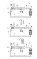
より具体的には、上記したものよりも若干大きなサイズのLHPに、図25に示したように、8つの温度センサ22a~22hを取り付けて行った実験から、図26A、図26Bに示した結果が得られている。なお、図25A、図25Bにおいて、Ta~Teとは、温度センサ22a~22hによって測定された温度のことである。
この結果は、液管17の,蒸発器11から離れた部分の温度Te、Tfや、蒸気管15の,凝縮器16近傍の部分の温度Thでは、作動液蒸気の凝縮液化を検出しにくいが、加熱対象部分の温度Taや、蒸発器11近傍部分の温度Tb、Tc、Td、Tgを用いれば、作動液蒸気の凝縮液化を検出できることを示すものである。
従って、各温度センサ22x(x=a~d)は、上記2状況で作動流体の相状態が異なる箇所、特に、加熱対象部分や蒸発器11近傍に取り付けておくことが望ましい。
なお、各温度センサ22xによって測定される,LHP10(LHP101~LHP104)の各部分の温度は、各部分内の作動流体の温度に相当するものでありさえすれば良い。従って、各温度センサ22xを、管壁(図3等参照)等に取り付けておく必要はなく、各温度センサ22x(温度センサ22xの,実際に温度を測定する部分;熱電対の先端部分等)を、管内に配置しておくことも出来る。
また、各実施形態に係る情報処理装置1は、LHP10に温度センサ22xを複数個取り付けたものであったが、1つの温度センサ22xによる温度の測定結果のみからでも、LHP10の状態が起動可能状態になったか否かを判定できる。従って、各実施形態に係る情報処理装置1を、1つの温度センサ22xのみがLHP10に取り付けられているものに変形することも出来る。なお、作動液蒸気の凝縮液化に起因する温度変化量(温度の変化速度の変化量)は、Ta、Tb、Tc、Tdの順で、小さくなっていく(図7参照)。そのため、1つの温度センサ22xのみをLHP10に取り付ける場合には、加熱対象部分の温度を測定するための温度センサ22aのみを取り付けておくことが望ましい。
また、上記した起動完了監視処理は、Ta~Tdの変化速度に基づき、LHP10の状態が起動可能状態となったか否かを判定する処理であったが、この起動完了監視処理の具体的な内容は、作動流体蒸気の凝縮液化に起因して実際に生ずる温度変化の内容に応じたものとすることが出来る。
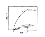
具体的には、LHP10の構成〔各部(蒸気管15等)のサイズ、LHP10の各部のプリント回路板30に対する位置関係等〕によっては、Ta、Tb、Tc、Tdが図27に示したように変化する場合もある。Ta、Tb、Tc、Tdがこのように変化する場合、起動完了監視処理を、Taについては、Taを周期的に測定すると共に、その最大値を管理し、今回の測定結果が、管理している最大値-α(例えば、3℃)以下となったときに、LHP10の状態が起動可能状態になったと判定する処理としておくことが出来る。なお、当然のことではあるが、この場合にも、Ta~Tdの変化速度に基づき、LHP10の状態が起動可能状態となったか否かを判定するタイプの起動完了監視処理を採用しておくことが出来る。
さらに、蒸気管15の加熱に必要以上のエネルギーが消費されてしまうことになるが、起動完了監視処理を、Taが、作動液蒸気が凝縮液化していることが確実な温度(例えば、50℃;図7参照。)になったときに、LHP10の状態が起動可能状態になったと判定する処理としておくことも出来る。
各LHP10を、蒸発器11(11′)と並列に幾つかの蒸発器11(11′)が設けられているもの(蒸気管15と液管17との間に、複数の蒸発器11(11′)が並列接続されているもの)に変形することも出来る。また、LHP102、104を、枝管の本数が3本以上の蒸気管15が用いられたものに変形することも出来る。さらに、情報処理装置1(ノートPC)を、LHP10が停止している間の自装置の姿勢を加速度計により検出することにより、蒸発器11内に作動液があるか否か(起動時に蒸気管15の加熱が必要であるか否か)を管理する装置に変形することも出来る。
開示の技術は、冷却が必要とされる各種分野で利用できる。
1 情報処理装置
101、102、103、104 ループ型ヒートパイプ(LHP)
11 蒸発器
12 ウィック
13 液溜室
15 蒸気管
15a、15b 枝管
15c 本管
16 凝縮器
17 液管
21 加熱装置
22a、22b、22c、22d 温度センサ
25 受熱ブロック
30 プリント回路板
31 制御装置
32 CPU
33 冷却用ファン
41 ポンプ
42 熱媒体循環流路
43 部材
101、102、103、104 ループ型ヒートパイプ(LHP)
11 蒸発器
12 ウィック
13 液溜室
15 蒸気管
15a、15b 枝管
15c 本管
16 凝縮器
17 液管
21 加熱装置
22a、22b、22c、22d 温度センサ
25 受熱ブロック
30 プリント回路板
31 制御装置
32 CPU
33 冷却用ファン
41 ポンプ
42 熱媒体循環流路
43 部材
Claims (14)
- 液体状態にある作動流体を発熱体からの熱で気化させる蒸発器と、気体状態にある作動流体を放熱により凝縮させる凝縮器とを、前記蒸発器からの作動流体を前記凝縮器に供給する蒸気管及び前記凝縮器からの作動流体を前記蒸発器に供給する液管によりループ状に接続したループ型ヒートパイプと、
前記ループ型ヒートパイプが熱輸送デバイスとして動作している状況下と、前記ループ型ヒートパイプが熱輸送デバイスとして動作しておらず,且つ,前記蒸発器内に液体状態にある作動流体が存在していない状況下とで、その内部の作動流体の相状態が異なる,前記ループ型ヒートパイプの部分の温度を測定する温度センサと、
前記蒸気管の一部である加熱対象部分を加熱する加熱装置と、
前記蒸発器の温度上昇では熱輸送デバイスとしての動作を開始しない状態にある前記ループ型ヒートパイプに熱輸送デバイスとしての動作を開始させるために、前記加熱装置を制御する制御装置であって、前記加熱装置に前記加熱対象部分を加熱させている間、前記温度センサを利用して前記ループ型ヒートパイプの前記部分の温度を監視し、当該温度に、前記ループ型ヒートパイプ内での作動流体の凝縮液化に起因する変化が生じたときに、前記加熱装置の加熱動作を停止させる制御装置と、
を備えることを特徴とするループ型ヒートパイプシステム。 - 前記ループ型ヒートパイプの前記蒸気管が、
本管及び前記本管から枝分かれした複数の枝管を有する,各枝管の開口端が前記蒸発器に接続され,前記本管の開口端が前記凝縮器と接続された部材であり、
前記加熱装置が、
前記ループ型ヒートパイプの前記複数の枝管の中の一部の枝管を加熱する装置である
ことを特徴とする請求項1に記載のループ型ヒートパイプシステム。 - 前記ループ型ヒートパイプが熱輸送デバイスとして動作している状況下と、前記ループ型ヒートパイプが熱輸送デバイスとして動作しておらず,且つ,前記蒸発器内に液体状の作動流体が存在していない状況下とで、その内部の作動流体の相状態が異なる,前記ループ型ヒートパイプの複数の部分のそれぞれについて、その温度を測定する温度センサを、備え、
前記制御装置が、
前記加熱装置に前記加熱対象部分を加熱させている間、各温度センサを利用して前記ループ型ヒートパイプの前記複数の部分のそれぞれの温度を監視し、いずれかの温度に、前記ループ型ヒートパイプ内での作動流体の凝縮液化に起因する変化が生じたときに、前記加熱装置の加熱動作を停止させる装置である
ことを特徴とする請求項1に記載のループ型ヒートパイプシステム。 - 前記温度センサが、前記蒸気管の途中に設けられている
ことを特徴とする請求項1に記載のループ型ヒートパイプシステム。 - 前記制御装置が、
前記ループ型ヒートパイプの状態が、前記加熱対象部分の加熱を行わなくても熱輸送デバイスとしての動作を開始する起動可能状態にあるか否かを判断し、前記ループ型ヒートパイプの状態が起動可能状態ではなかった場合に、前記加熱装置を制御する装置である
ことを特徴とする請求項1に記載のループ型ヒートパイプシステム。 - 前記蒸発器が、作動流体を一時的に貯留する液溜室を備えている
ことを特徴とする請求項1に記載のループ型ヒートパイプシステム。 - 前記加熱装置が、
前記ループ型ヒートパイプに、前記凝縮器が鉛直下側を向き、且つ、液体状の作動流体が前記凝縮器側にのみ存在する状態を取らせた場合における前記蒸気管内の作動流体の液面位置より鉛直下方側の部分を前記加熱対象部分として加熱する装置である
ことを特徴とする請求項1に記載のループ型ヒートパイプシステム。 - 前記加熱装置が、
その内部を熱媒体が循環可能な、前記発熱体が発生した熱を前記加熱対象部分に伝える熱媒体循環流路と、前記熱媒体循環流路内の熱媒体を循環させる、前記制御装置により制御されるポンプとを備えた装置である
ことを特徴とする請求項1に記載のループ型ヒートパイプシステム。 - 液体状態にある作動流体を発熱体からの熱で気化させる蒸発器と、気体状態にある作動流体を放熱により凝縮させる凝縮器と、前記凝縮器からの作動流体を前記蒸発器に供給する液管と、本管及び前記本管から枝分かれした複数の枝管を有し,各枝管の開口端が前記蒸発器に接続され,前記本管の開口端が前記凝縮器と接続された蒸気管とを含むループ型ヒートパイプと、
前記ループ型ヒートパイプの前記複数の枝管の中の一部の枝管を加熱する加熱装置と、
を備えることを特徴とするループ型ヒートパイプシステム。 - 動作時に冷却すべき電子部品と、
液体状態にある作動流体を前記電子部品からの熱で気化させる蒸発器と、気体状態にある作動流体を放熱により凝縮させる凝縮器とを、前記蒸発器からの作動流体を前記凝縮器に導入する蒸気管及び前記凝縮器からの作動流体を前記蒸発器に導入する液管によりループ状に接続したループ型ヒートパイプと、
前記ループ型ヒートパイプが熱輸送デバイスとして動作している状況下と、前記ループ型ヒートパイプが熱輸送デバイスとして動作しておらず,且つ,前記蒸発器内に液体状の作動流体が存在していない状況下とで、その内部の作動流体の相状態が異なる,前記ループ型ヒートパイプの部分の温度を測定する温度センサと、
前記蒸気管の一部である加熱対象部分を加熱する加熱装置と、
前記蒸発器の温度上昇では熱輸送デバイスとしての動作を開始しない状態にある前記ループ型ヒートパイプに熱輸送デバイスとしての動作を開始させるために、前記加熱装置を制御する制御装置であって、前記加熱装置に前記加熱対象部分を加熱させている間、前記温度センサを利用して前記ループ型ヒートパイプの前記部分の温度を監視し、当該温度に、前記ループ型ヒートパイプ内での作動流体の凝縮液化に起因する変化が生じたときに、前記加熱装置の加熱動作を停止させる制御装置と
を備えることを特徴とする情報処理装置。 - 前記制御装置が、
前記ループ型ヒートパイプの状態が、前記加熱対象部分の加熱を行わなくても熱輸送デバイスとしての動作を開始する起動可能状態にあるか否かを判断し、前記ループ型ヒートパイプの状態が前記起動可能状態ではなかった場合に、前記加熱装置を制御する装置である
ことを特徴とする請求項10に記載の情報処理装置。 - 前記制御装置が、
動作開始後の前記電子部品の温度変化パターンに基づき、前記ループ型ヒートパイプの状態が前記起動可能状態にあるか否かを判断する装置である
ことを特徴とする請求項11に記載の情報処理装置。 - 前記制御装置が、
前記加熱装置による前記加熱対象部分の加熱開始時に、前記電子部品の動作を停止させ、前記加熱装置による前記加熱対象部分の加熱停止時に、前記電子部品の動作を開始させる装置である
ことを特徴とする請求項10に記載の情報処理装置。 - 前記ループ型ヒートパイプの前記蒸気管が、
本管及び前記本管から枝分かれした複数の枝管を有する,各枝管の開口端が前記蒸発器に接続され,前記本管の開口端が前記凝縮器と接続された部材であり、
前記加熱装置が、
前記ループ型ヒートパイプの前記複数の枝管の中の一部の枝管を加熱する装置である
ことを特徴とする請求項11に記載の情報処理装置。
Priority Applications (2)
| Application Number | Priority Date | Filing Date | Title |
|---|---|---|---|
| JP2011541824A JP5360226B2 (ja) | 2009-11-19 | 2010-05-20 | ループ型ヒートパイプシステム及び情報処理装置 |
| US13/473,922 US9455212B2 (en) | 2009-11-19 | 2012-05-17 | Loop heat pipe system and information processing apparatus |
Applications Claiming Priority (2)
| Application Number | Priority Date | Filing Date | Title |
|---|---|---|---|
| JP2009-263888 | 2009-11-19 | ||
| JP2009263888 | 2009-11-19 |
Related Child Applications (1)
| Application Number | Title | Priority Date | Filing Date |
|---|---|---|---|
| US13/473,922 Continuation US9455212B2 (en) | 2009-11-19 | 2012-05-17 | Loop heat pipe system and information processing apparatus |
Publications (1)
| Publication Number | Publication Date |
|---|---|
| WO2011061952A1 true WO2011061952A1 (ja) | 2011-05-26 |
Family
ID=44059438
Family Applications (1)
| Application Number | Title | Priority Date | Filing Date |
|---|---|---|---|
| PCT/JP2010/058500 Ceased WO2011061952A1 (ja) | 2009-11-19 | 2010-05-20 | ループ型ヒートパイプシステム及び情報処理装置 |
Country Status (3)
| Country | Link |
|---|---|
| US (1) | US9455212B2 (ja) |
| JP (1) | JP5360226B2 (ja) |
| WO (1) | WO2011061952A1 (ja) |
Cited By (2)
| Publication number | Priority date | Publication date | Assignee | Title |
|---|---|---|---|---|
| US10412350B2 (en) | 2017-01-06 | 2019-09-10 | Seiko Epson Corporation | Heat transport device and projector |
| KR20210114030A (ko) * | 2019-03-15 | 2021-09-17 | 가부시기 가이샤 시마즈 세이사구쇼 | 냉각 장치 |
Families Citing this family (6)
| Publication number | Priority date | Publication date | Assignee | Title |
|---|---|---|---|---|
| GB2507732A (en) * | 2012-11-07 | 2014-05-14 | Oclaro Technology Ltd | Laser temperature control |
| ES2648877T3 (es) * | 2012-12-28 | 2018-01-08 | Ibérica Del Espacio, S.A. | Aparato de tubo de calor en bucle para transmisión de calor y control térmico |
| DE102013010088A1 (de) * | 2013-06-18 | 2014-12-18 | VENSYS Elektrotechnik GmbH | Kühlvorrichtung für ein Stromumrichtermodul |
| CN103868282A (zh) * | 2014-04-02 | 2014-06-18 | 深圳市庄合智能产业科技有限公司 | 一种超导蒸发式热泵机组 |
| KR102015917B1 (ko) * | 2018-01-02 | 2019-08-29 | 엘지전자 주식회사 | 열전 모듈을 이용하는 냉각 장치 |
| US11143429B2 (en) * | 2018-04-06 | 2021-10-12 | Ecobee Inc. | Control device for HVAC fan coil units |
Citations (4)
| Publication number | Priority date | Publication date | Assignee | Title |
|---|---|---|---|---|
| JPS5719779U (ja) * | 1980-07-04 | 1982-02-01 | ||
| FR2755219A3 (fr) * | 1996-10-30 | 1998-04-30 | N Proizv Objedinenie Im Sa Lav | Tube thermique de circuit |
| JP2002340489A (ja) * | 2001-05-15 | 2002-11-27 | Hitachi Ltd | ループ型ヒートパイプ |
| US20030205364A1 (en) * | 2001-06-29 | 2003-11-06 | Ioan Sauciuc | Method and apparatus for dissipating heat from an electronic device |
Family Cites Families (25)
| Publication number | Priority date | Publication date | Assignee | Title |
|---|---|---|---|---|
| US3934643A (en) * | 1971-07-26 | 1976-01-27 | Nikolaus Laing | Controllable heat pipe |
| US4067237A (en) * | 1976-08-10 | 1978-01-10 | Westinghouse Electric Corporation | Novel heat pipe combination |
| US4222436A (en) * | 1978-12-21 | 1980-09-16 | Dynatherm Corporation | Heat exchange apparatus |
| US4370547A (en) * | 1979-11-28 | 1983-01-25 | Varian Associates, Inc. | Variable thermal impedance |
| JPS5719779A (en) | 1980-07-11 | 1982-02-02 | Canon Kk | Electronic geography learning machine |
| US4898231A (en) | 1985-09-30 | 1990-02-06 | Kabushiki Kaisha Toshiba | Heat-pipe system and method of and apparatus for controlling a flow rate of a working fluid in a liquid pipe of the heat pipe system |
| JPS62284191A (ja) | 1986-06-02 | 1987-12-10 | Toshiba Corp | ヒ−トパイプ |
| US4765396A (en) | 1986-12-16 | 1988-08-23 | The United States Of America As Represented By The Administrator Of The National Aeronautics And Space Administration | Polymeric heat pipe wick |
| US5289869A (en) * | 1992-12-17 | 1994-03-01 | Klein John F | Closed loop feedback control variable conductance heat pipe |
| JP2609217B2 (ja) | 1995-04-19 | 1997-05-14 | 株式会社フジクラ | ループ式ヒートパイプの作動液の循環制御装置 |
| US7931072B1 (en) | 2002-10-02 | 2011-04-26 | Alliant Techsystems Inc. | High heat flux evaporator, heat transfer systems |
| US8136580B2 (en) | 2000-06-30 | 2012-03-20 | Alliant Techsystems Inc. | Evaporator for a heat transfer system |
| US8047268B1 (en) | 2002-10-02 | 2011-11-01 | Alliant Techsystems Inc. | Two-phase heat transfer system and evaporators and condensers for use in heat transfer systems |
| US7708053B2 (en) | 2000-06-30 | 2010-05-04 | Alliant Techsystems Inc. | Heat transfer system |
| US7251889B2 (en) | 2000-06-30 | 2007-08-07 | Swales & Associates, Inc. | Manufacture of a heat transfer system |
| US7549461B2 (en) | 2000-06-30 | 2009-06-23 | Alliant Techsystems Inc. | Thermal management system |
| ATE319972T1 (de) | 2000-06-30 | 2006-03-15 | Swales Aerospace | Phasenregelung in einem kapillarverdampfer |
| US7004240B1 (en) | 2002-06-24 | 2006-02-28 | Swales & Associates, Inc. | Heat transport system |
| US8109325B2 (en) | 2000-06-30 | 2012-02-07 | Alliant Techsystems Inc. | Heat transfer system |
| JP4204187B2 (ja) | 2000-12-07 | 2009-01-07 | 三菱電機株式会社 | ループヒートパイプ |
| US7061446B1 (en) * | 2002-10-24 | 2006-06-13 | Raytheon Company | Method and apparatus for controlling temperature gradients within a structure being cooled |
| WO2004040218A2 (en) | 2002-10-28 | 2004-05-13 | Swales & Associates, Inc. | Heat transfer system |
| JP2009115396A (ja) | 2007-11-07 | 2009-05-28 | Fujitsu Ltd | ループ型ヒートパイプ |
| JP5061911B2 (ja) | 2008-01-11 | 2012-10-31 | 富士通株式会社 | ループ型ヒートパイプおよび電子機器 |
| JP5125889B2 (ja) * | 2008-08-28 | 2013-01-23 | 三菱電機株式会社 | 可変コンダクタンスヒートパイプ |
-
2010
- 2010-05-20 WO PCT/JP2010/058500 patent/WO2011061952A1/ja not_active Ceased
- 2010-05-20 JP JP2011541824A patent/JP5360226B2/ja active Active
-
2012
- 2012-05-17 US US13/473,922 patent/US9455212B2/en active Active
Patent Citations (4)
| Publication number | Priority date | Publication date | Assignee | Title |
|---|---|---|---|---|
| JPS5719779U (ja) * | 1980-07-04 | 1982-02-01 | ||
| FR2755219A3 (fr) * | 1996-10-30 | 1998-04-30 | N Proizv Objedinenie Im Sa Lav | Tube thermique de circuit |
| JP2002340489A (ja) * | 2001-05-15 | 2002-11-27 | Hitachi Ltd | ループ型ヒートパイプ |
| US20030205364A1 (en) * | 2001-06-29 | 2003-11-06 | Ioan Sauciuc | Method and apparatus for dissipating heat from an electronic device |
Cited By (4)
| Publication number | Priority date | Publication date | Assignee | Title |
|---|---|---|---|---|
| US10412350B2 (en) | 2017-01-06 | 2019-09-10 | Seiko Epson Corporation | Heat transport device and projector |
| KR20210114030A (ko) * | 2019-03-15 | 2021-09-17 | 가부시기 가이샤 시마즈 세이사구쇼 | 냉각 장치 |
| KR102565929B1 (ko) * | 2019-03-15 | 2023-08-10 | 가부시기 가이샤 시마즈 세이사구쇼 | 냉각 장치 |
| US12359878B2 (en) | 2019-03-15 | 2025-07-15 | Shimadzu Corporation | Dryout detection for cooling device |
Also Published As
| Publication number | Publication date |
|---|---|
| US9455212B2 (en) | 2016-09-27 |
| JPWO2011061952A1 (ja) | 2013-04-04 |
| US20120227954A1 (en) | 2012-09-13 |
| JP5360226B2 (ja) | 2013-12-04 |
Similar Documents
| Publication | Publication Date | Title |
|---|---|---|
| JP5360226B2 (ja) | ループ型ヒートパイプシステム及び情報処理装置 | |
| JP5061911B2 (ja) | ループ型ヒートパイプおよび電子機器 | |
| CN102472597A (zh) | 环型热导管及其起动方法 | |
| CN104246649B (zh) | 服务器用油冷式冷却装置及其驱动方法 | |
| JP4767879B2 (ja) | 恒温恒湿器 | |
| JP2010054122A (ja) | 可変コンダクタンスヒートパイプ | |
| US20120216992A1 (en) | Dew-condensation detecting apparatus, electronic equipment cooling system, and dew-condensation detecting method | |
| JP5304479B2 (ja) | 熱輸送デバイス、電子機器 | |
| JP5321716B2 (ja) | ループ型ヒートパイプおよび電子機器 | |
| US20150068702A1 (en) | Dew condensation detecting device, cooling system and cooling medium flow rate controlling method | |
| JP2010008025A (ja) | ループヒートパイプおよび電子機器 | |
| JP4645373B2 (ja) | 電子部品の温度制御装置並びにハンドラ装置 | |
| JP2010225111A (ja) | 電子機器 | |
| JP2013194919A (ja) | 自励振動ヒートパイプ及びプログラム | |
| JP2012185184A (ja) | 電子部品の温度制御装置並びにハンドラ装置 | |
| JP6015209B2 (ja) | 温度調節装置、温度調節方法、電子装置の製造方法及び温度調節プログラム | |
| KR100736354B1 (ko) | 급냉·급가열이 가능한 히트파이프 구조 및 이를 이용한탱크구조 | |
| JP5189776B2 (ja) | 冷却装置 | |
| CN101304718B (zh) | 蒸汽发生器 | |
| JP2015095614A (ja) | 冷却装置およびこれを搭載した電子機器 | |
| JP5071531B2 (ja) | 電子部品の温度制御装置並びにハンドラ装置 | |
| JP4964614B2 (ja) | 冷却装置 | |
| JP6588388B2 (ja) | 発熱体冷却システム | |
| JP2001091170A (ja) | 熱搬送装置 | |
| KR20090130911A (ko) | 열매체를 이용한 온풍 장치 |
Legal Events
| Date | Code | Title | Description |
|---|---|---|---|
| 121 | Ep: the epo has been informed by wipo that ep was designated in this application |
Ref document number: 10831351 Country of ref document: EP Kind code of ref document: A1 |
|
| WWE | Wipo information: entry into national phase |
Ref document number: 2011541824 Country of ref document: JP |
|
| NENP | Non-entry into the national phase |
Ref country code: DE |
|
| 122 | Ep: pct application non-entry in european phase |
Ref document number: 10831351 Country of ref document: EP Kind code of ref document: A1 |