WO2011059005A1 - 電子血圧計 - Google Patents
電子血圧計 Download PDFInfo
- Publication number
- WO2011059005A1 WO2011059005A1 PCT/JP2010/070035 JP2010070035W WO2011059005A1 WO 2011059005 A1 WO2011059005 A1 WO 2011059005A1 JP 2010070035 W JP2010070035 W JP 2010070035W WO 2011059005 A1 WO2011059005 A1 WO 2011059005A1
- Authority
- WO
- WIPO (PCT)
- Prior art keywords
- air port
- pressure
- pressure sensor
- air
- connection head
- Prior art date
- Legal status (The legal status is an assumption and is not a legal conclusion. Google has not performed a legal analysis and makes no representation as to the accuracy of the status listed.)
- Ceased
Links
Images






Classifications
-
- A—HUMAN NECESSITIES
- A61—MEDICAL OR VETERINARY SCIENCE; HYGIENE
- A61B—DIAGNOSIS; SURGERY; IDENTIFICATION
- A61B5/00—Measuring for diagnostic purposes; Identification of persons
- A61B5/02—Detecting, measuring or recording for evaluating the cardiovascular system, e.g. pulse, heart rate, blood pressure or blood flow
- A61B5/021—Measuring pressure in heart or blood vessels
- A61B5/022—Measuring pressure in heart or blood vessels by applying pressure to close blood vessels, e.g. against the skin; Ophthalmodynamometers
-
- A—HUMAN NECESSITIES
- A61—MEDICAL OR VETERINARY SCIENCE; HYGIENE
- A61B—DIAGNOSIS; SURGERY; IDENTIFICATION
- A61B5/00—Measuring for diagnostic purposes; Identification of persons
- A61B5/02—Detecting, measuring or recording for evaluating the cardiovascular system, e.g. pulse, heart rate, blood pressure or blood flow
- A61B5/021—Measuring pressure in heart or blood vessels
- A61B5/02141—Details of apparatus construction, e.g. pump units or housings therefor, cuff pressurising systems, arrangements of fluid conduits or circuits
-
- A—HUMAN NECESSITIES
- A61—MEDICAL OR VETERINARY SCIENCE; HYGIENE
- A61B—DIAGNOSIS; SURGERY; IDENTIFICATION
- A61B5/00—Measuring for diagnostic purposes; Identification of persons
- A61B5/68—Arrangements of detecting, measuring or recording means, e.g. sensors, in relation to patient
- A61B5/6801—Arrangements of detecting, measuring or recording means, e.g. sensors, in relation to patient specially adapted to be attached to or worn on the body surface
- A61B5/6813—Specially adapted to be attached to a specific body part
- A61B5/6824—Arm or wrist
Definitions
- the present invention relates to an electronic sphygmomanometer, and more particularly to an electronic sphygmomanometer that improves the reliability of blood pressure measurement values.
- Blood pressure is one of the indicators for analyzing cardiovascular diseases. Analyzing the risk of cardiovascular disease based on blood pressure is effective in preventing cardiovascular diseases such as stroke, heart failure and myocardial infarction.
- cardiovascular diseases such as stroke, heart failure and myocardial infarction.
- early morning hypertension in which blood pressure rises in the early morning, is related to heart disease and stroke.
- morning surge a symptom of a sudden rise in blood pressure between 1 hour and 1.5 hours after waking up, called morning surge, has a causal relationship with stroke.
- grasping the correlation between time (lifestyle) and blood pressure change is useful for risk analysis of cardiovascular diseases. Therefore, it is necessary to continuously measure blood pressure over a long period of time.
- Patent Document 1 In order to improve the measurement accuracy by the sphygmomanometer, according to the invention disclosed in Japanese Patent Application Laid-Open No. 7-51233 (hereinafter referred to as Patent Document 1), an error in the measured value depending on the characteristics of the pressure sensor for blood pressure measurement is reduced. Processing for correction is performed at the time of production of the electronic blood pressure monitor.
- Patent Document 2 Japanese Patent Laid-Open No. 2-19133
- Patent Document 3 US Pat. No. 7,594,892
- blood pressure measurement is performed using two pressure sensors. Techniques for improving the reliability of values are disclosed.
- correction for the pressure sensor is performed based on the difference in characteristics of individual electronic sphygmomanometers at the time of production of the electronic sphygmomanometer.
- regular calibration is not performed except in certain situations, such as when it breaks down.
- some blood pressure monitors for medical facilities are equipped with two pressure sensors and monitor pressure based on the output of these pressure sensors.
- the functions of the two pressure sensors have been used for other purposes. That is, the blood pressure is calculated based on the cuff pressure information obtained by one pressure sensor, and abnormality is detected based on the output of the other pressure sensor.
- an abnormality is detected when the detected pressure value of the pressure sensor greatly exceeds 300 mmHg, for example.
- the pump is stopped and the valve is opened to ensure safety. Therefore, the other pressure sensor is applied for safety measures stipulated in the Japanese medical standard IEC 60601-2-30, and does not guarantee the accuracy of one pressure sensor used for blood pressure measurement. It was.
- the accuracy of one pressure sensor for blood pressure calculation needs to be guaranteed by the pressure sensor itself.
- the pressure sensor is expensive because a highly accurate pressure sensor with little secular change is required without being affected by disturbances such as temperature changes.
- the failure rate of the sphygmomanometer due to the failure of the pressure sensor is simply doubled compared to a sphygmomanometer having one pressure sensor.
- a pressure sensor used in an electronic sphygmomanometer measures the pressure of a gas or liquid with a pressure sensitive element via a diaphragm (stainless diaphragm, silicon diaphragm, etc.), converts it into an electrical signal, and outputs it.
- a diaphragm stainless diaphragm, silicon diaphragm, etc.
- a semiconductor strain gauge is provided on the surface of the diaphragm, and a change in electric resistance due to a piezoresistance effect generated by deformation of the diaphragm due to external force (pressure) is observed. Convert to electrical signal.
- a capacitance is generated by forming a capacitor by making the glass fixed pole and the silicon movable pole face each other, and deforming the movable pole by external force (pressure). Is converted into an electrical signal.
- Patent Documents 1 to 3 do not disclose or examine a specific structure around the pressure sensor.
- JP 7-51233 A Japanese Patent Laid-Open No. 2-19133 US Pat. No. 7,594,892
- an object of the present invention is to provide an electronic sphygmomanometer having a structure around a pressure sensor that can improve the reliability of blood pressure measurement values in the arrangement structure of the pressure sensor used in the electronic sphygmomanometer. is there.
- An electronic sphygmomanometer includes a cuff attached to a measurement site, a pressurization / decompression device for adjusting a pressure applied to the cuff, and a pressure sensor, and is based on pressure information output from the pressure sensor.
- a pressure detection device for detecting the cuff pressure in the cuff; and a blood pressure calculation device for calculating a blood pressure based on a change in the cuff pressure detected by the pressure detection device.
- the pressure sensor is disposed on a first main surface of an internal substrate, and the pressure sensor has an air port that protrudes to a second main surface side opposite to the first main surface of the internal substrate, A pressure sensor air tube is connected to the air port, and a branch air tube branched from the cuff air tube connected to the cuff is connected to the pressure sensor air tube.
- the pressure sensor air tube has an air port connection head connected to the air port, and an engagement region that engages the air port connection head with the internal substrate between the air port connection head and the internal substrate. Is provided.
- the internal substrate is provided with an opening for exposing the air port on the second main surface side, and is disposed with a predetermined gap from the second main surface.
- the air port connecting head includes a protruding member as the engaging region that engages with the inner surface side of the shield plate at the opening when the air port connecting head is connected to the air port on the outer peripheral surface thereof.
- the pressure sensor includes a first pressure sensor and a second pressure sensor, and the pressure detection device is output from the first pressure sensor and the second pressure sensor.
- the cuff pressure in the cuff is detected based on pressure information
- the air port includes a first air port of the first pressure sensor and a second air port of the second pressure sensor as the air ports.
- a second opening that exposes the second air port, and a second shield plate disposed at a predetermined gap from the second main surface, and the pressure sensor air tube includes the first air port.
- Airpo A first air port connecting head connected to the second air port and a second air port connecting head connected to the second air port, and the first air port connecting head is connected to the first air port on an outer peripheral surface thereof.
- the second air port connecting head is connected to the second air port on the outer peripheral surface thereof.
- the protrusion member that engages with the inner surface side of the second shield plate in the second opening is provided.
- two or more protruding members are provided on the outer surface of the airport connection head.
- the electronic sphygmomanometer based on the present invention, it is possible to provide an electronic sphygmomanometer having a pressure sensor arrangement structure that makes it possible to improve the reliability of blood pressure measurement values.
- FIG. 10 is a cross-sectional view taken along line XX in FIG. 9.
- FIG. 10 is a cross-sectional view showing still another structure of the air tube used in the electronic sphygmomanometer according to the embodiment and corresponding to the XX line arrow in FIG. 9.
- FIG. 10 is a cross-sectional view taken along line XX in FIG. 9.
- FIG. 10 is a cross-sectional view showing still another structure of the air tube used in the electronic sphygmomanometer according to the embodiment and corresponding to the XX line arrow in FIG. 9. It is a perspective view which shows other structure of the air tube used for the electronic blood pressure monitor in embodiment. It is a perspective view which shows other structure of the air tube used for the electronic blood pressure monitor in embodiment. It is sectional drawing which shows the fixation structure of the air tube used for the electronic blood pressure monitor in embodiment. It is a 1st sectional view showing a fixation step of an air tube used for an electronic sphygmomanometer in an embodiment. It is a 2nd sectional view showing the fixation step of the air tube used for the electronic sphygmomanometer in the embodiment.
- an electronic sphygmomanometer will be described in which the measurement site is the upper arm, blood pressure is calculated by the oscillometric method, and two pressure sensors are mounted as an example. Note that the method applied for blood pressure calculation is not limited to the oscillometric method.
- FIG. 1 is a view showing an appearance of an electronic sphygmomanometer 1 according to an embodiment of the present invention.
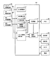
- FIG. 2 is a block diagram showing a hardware configuration of the electronic blood pressure monitor according to the embodiment of the present invention.
- electronic blood pressure monitor 1 includes a main body portion 10, a front cover 11, and a cuff 20 that can be wound around the upper arm of the measurement subject.
- the cuff 20 includes an air bag 21.
- the main body unit 10 includes a CPU (Central Processing Unit) 100 for centrally controlling each unit and performing various arithmetic processes, and for causing the CPU 100 to perform predetermined operations.
- a processing memory 42 for storing programs and data; a data storage memory 43 for storing measured blood pressure data; a power supply 44 for supplying power to each part of the main body 10; And a timer 45 for measuring time and outputting time-measured data to the CPU 100.
- the operation unit 41 includes a measurement / stop switch 41 ⁇ / b> A that receives an instruction to turn on or off the power supply and a measurement start / end instruction, a timer set switch 41 ⁇ / b> B that is operated to set the timer 45, and a memory 43.
- the memory switch 41C for receiving information such as blood pressure data stored in the memory 43 and displaying it on the display unit 40, and instructions for raising / lowering the number when the timer is set and the memory number when calling the memory It has arrow switches 41D and 41E for receiving.
- the main body 10 further has a cuff pressure adjusting mechanism including a pump 51 and an exhaust valve (hereinafter referred to as a valve) 52.
- the air system including the first pressure sensor 321 and the second pressure sensor 322 for detecting the pressure (cuff pressure) in the pump 51, the valve 52, and the air bladder 21 is connected to the cuff 20 via the cuff air tube 31. It is connected to the air bag 21 to be included.
- the main body 10 further includes the air system described above, a cuff pressure adjusting mechanism, a first oscillation circuit 331, and a second oscillation circuit 332.
- the cuff pressure adjusting mechanism includes a pump drive circuit 53 and a valve drive circuit 54 in addition to the pump 51 and the valve 52.
- the pump 51 supplies air to the air bladder 21 in order to increase the cuff pressure.
- the valve 52 is opened and closed to exhaust or seal the air in the air bladder 21.
- the pump drive circuit 53 controls the drive of the pump 51 based on a control signal given from the CPU 100.
- the valve drive circuit 54 performs opening / closing control of the valve 52 based on a control signal given from the CPU 100.
- a capacitance type pressure sensor is used as an example.
- the capacitance value changes according to the cuff pressure to be detected.
- Each of the first oscillation circuit 331 and the second oscillation circuit 332 is connected to a corresponding pressure sensor, and oscillates based on the capacitance value of the corresponding pressure sensor.
- a signal having a frequency corresponding to the capacity value of the corresponding pressure sensor (hereinafter referred to as a frequency signal) is output.
- the output frequency signal is given to the CPU 100.
- the CPU 100 detects the pressure by converting the frequency signal input from the first oscillation circuit 331 or the second oscillation circuit 332 into a pressure.
- FIG. 3 shows a functional configuration of the electronic sphygmomanometer 1 according to the present embodiment.
- the CPU 100 includes a pressure adjustment unit 111, a blood pressure calculation unit 112, a sensor abnormality detection unit 113, a recording unit 114, and a display processing unit 115.
- the pressure adjusting unit 111 controls the pump 51 and the valve 52 via the pump driving circuit 53 and the valve driving circuit 54, and flows the air into and out of the air bag 21 via the cuff air tube 31, whereby the cuff pressure Adjust.
- the blood pressure calculation unit 112 detects pulse wave amplitude information based on a frequency signal input from the first oscillation circuit 331 or the second oscillation circuit 332 (this frequency signal indicates a pressure information signal), and the detected pulse wave amplitude information Based on the oscillometric method, systolic blood pressure and diastolic blood pressure are calculated, and the pulse rate per predetermined time is calculated based on the detected pulse wave amplitude information.
- the pulse wave amplitude is based on the cuff pressure input from the first oscillation circuit 331 or the second oscillation circuit 332.
- Information is detected, and the systolic blood pressure and diastolic blood pressure of the measurement subject are calculated based on the detected pulse wave amplitude information.
- Conventionally known methods can be applied to blood pressure calculation and pulse calculation according to the oscillometric method by the blood pressure calculation unit 112.
- the sensor abnormality detection unit 113 receives the frequency signals output from the first oscillation circuit 331 and the second oscillation circuit 332, and analyzes the input signals to thereby detect abnormalities in the first pressure sensor 321 and the second pressure sensor 322. Is detected.
- the recording unit 114 has a function of reading data from the memory 43 or writing to the memory 43. Specifically, the output data from the blood pressure calculation unit 112 is input, and the input data (blood pressure measurement data) is stored in a predetermined storage area of the memory 43. Further, the output data from the sensor abnormality detection unit 113 is input, and the input data (pressure sensor abnormality detection result) is stored in a predetermined storage area of the memory 43. Further, the recording unit 114 reads out measurement data from a predetermined storage area of the memory 43 based on the operation of the memory switch 41 ⁇ / b> C of the operation unit 41 and outputs it to the display processing unit 115.
- the display processing unit 115 inputs the given data, converts it into a displayable format, and displays it on the display unit 40.
- FIG. 3 shows only a portion of the peripheral circuit of the CPU 100 that directly inputs and outputs with the CPU 100.
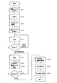
- the flowchart showing the processing procedure in FIG. 4 is stored in advance in the memory 42 as a program, and the blood pressure measurement processing in FIG. 4 is realized by the CPU 100 reading the program from the memory 42 and executing an instruction.
- step ST1 when the measurement subject operates (presses) the measurement / stop switch 41A (step ST1), the CPU 100 initializes a working memory (not shown) (ST2).
- the measurement subject wraps the cuff 20 around the measurement site (upper arm) of the measurement subject and wears it.
- the pressure adjustment unit 111 outputs a control signal to the pump drive circuit 53 and the valve drive circuit 54.
- the pump drive circuit 53 and the valve drive circuit 54 drive the pump 51 after closing the valve 52 based on the control signal.
- the cuff pressure is gradually increased to a predetermined pressure (steps ST5 and ST6).
- the pressure adjusting unit 111 After pressurizing to a predetermined pressure ( ⁇ predetermined pressurization value in step ST6), the pressure adjusting unit 111 outputs a control signal to the pump drive circuit 53 and the valve drive circuit 54.
- the pump drive circuit 53 and the valve drive circuit 54 stop the pump 51 based on the control signal, and then control the valve 52 to open gradually. Thereby, the cuff pressure is gradually reduced (step ST7).
- the blood pressure calculation unit 112 is based on the frequency signal output from the first oscillation circuit 331 or the second oscillation circuit 332, that is, based on the cuff pressure signal detected by the first pressure sensor 321 or the second pressure sensor 322. Based on the detected pulse wave amplitude information, a predetermined calculation is performed on the detected pulse wave amplitude information. By this calculation, systolic blood pressure and diastolic blood pressure are calculated (steps ST8 and ST9).
- the pulse wave amplitude information represents the volume change component of the artery at the measurement site and is included in the detected cuff pressure signal.
- an operation according to the change in the characteristics of the pressure sensor is performed.
- the blood pressure measurement is not limited to the decompression process, and may be performed in the pressurization process (step ST5).
- the pressure adjustment unit 111 When the systolic blood pressure and the diastolic blood pressure are calculated and determined (YES in step ST9), the pressure adjustment unit 111 fully opens the valve 52 via the valve drive circuit 54 and rapidly exhausts the air in the cuff 20 (step ST10). ).
- Blood pressure data calculated by the blood pressure calculation unit 112 is output to the display processing unit 115 and the recording unit 114.
- the display processing unit 115 inputs blood pressure data and displays it on the display unit 40 (step ST11).
- the recording unit 114 inputs blood pressure data, associates the time data input from the timer 45, and stores it in a predetermined storage area of the memory 43 (step ST12).
- the blood pressure calculation unit 112 can also calculate the pulse rate based on the detected pulse wave amplitude information.
- the calculated pulse rate is displayed on the display unit 40 by the display processing unit 115 and stored in the memory 43 in association with the blood pressure data by the recording unit 114.
- the operation so far is the same as that of a conventional blood pressure monitor.
- the blood pressure measurement value is a normal value (for example, If it is significantly different from the previous day's measurement value (measured value at the hospital, etc.) (for example, if it is more than 10mmHg), it is unclear whether it is due to physiological information of the living body or because the pressure sensor has failed There was a sense of anxiety.
- the electronic sphygmomanometer 1 includes the first pressure sensor 321 and the second pressure sensor 322, and calculates the average value of the cuff pressure detected by these pressure sensors as the blood pressure. Therefore, even if the detection accuracy of one of the pressure sensors varies due to secular change, the reliability of the blood pressure measurement value can be improved by calculating the average value.
- FIG. 5 is a perspective view showing the internal structure of the electronic sphygmomanometer 1 according to the present embodiment with the front cover 11 removed from the main body 10.
- the electronic sphygmomanometer 1 according to the present embodiment has a structure in which the surface cover 11 is inclined in a state where it is placed on the placement surface B.
- the user (measured person) side (front side: H1 in FIG. 5).
- the front cover 11 is inclined (Y direction in FIG. 5) so that the side) is low and the back side (H2 side in FIG. 5) is high. Therefore, the internal substrate 12 accommodated in the interior is also arranged in parallel with the surface cover 11, and is inclined so that the front side (H1 side in FIG. 5) is low and the back side (H2 side in FIG. 5) is high. Yes.
- the first pressure sensor 321 and the second pressure sensor 322 intersect the inclination direction of the surface cover 11 of the electronic sphygmomanometer 1 on the surface side 12 a that is the first main surface of the internal substrate 12. It arrange
- the first pressure sensor 321 and the second pressure sensor 322 are arranged in a direction orthogonal to the inclination direction of the surface cover 11 of the electronic sphygmomanometer 1.
- 6 and 7 are views of the internal substrate 12 as viewed from the back surface side, which is the second main surface opposite to the first main surface.
- FIG. 6 shows a state in which the pressure sensor air tube 500 is not attached to the first pressure sensor 321 and the second pressure sensor 322, and FIG. 7 shows the pressure applied to the first pressure sensor 321 and the second pressure sensor 322. The state where the sensor air tube 500 is mounted is shown.
- a predetermined distance (L1) is set so that the first air port 327 of the first pressure sensor 321 and the second air port 328 of the second pressure sensor 322 protrude. They are spaced apart.
- a first oscillation circuit is formed on the back surface 12 b of the internal substrate 12 positioned around the first air port 327, and a first shield plate 323 for protecting the first oscillation circuit is provided on the internal substrate 12. It is attached on the back surface 12b.
- the first shield plate 323 is provided with a first opening 325 for exposing the first air port 327.
- a predetermined gap is formed between the first shield plate 323 and the back surface of the internal substrate 12.
- a second oscillation circuit is also formed on the back surface 12b of the internal substrate 12 positioned around the second air port 328, and a second shield plate 324 for protecting the second oscillation circuit is provided on the internal substrate. 12 is attached on the rear surface 12b.
- the second shield plate 324 is provided with a second opening 326 for exposing the second air port 328.
- a predetermined gap is formed between the second shield plate 324 and the back surface of the internal substrate 12.
- a pressure sensor air tube 500 is attached to the first air port 327 of the first pressure sensor 321 and the second air port 328 of the second pressure sensor 322.
- a branch air tube 401 branched from the cuff air tube 31 is connected to the pressure sensor air tube 500.
- the pressure sensor air tube 500 is provided in the first air port connection head 501 connected to the first air port 327, the second air port connection head 502 connected to the second air port 328, and the first air port connection head 501. It has the 1st connection tube 503 to which the branch air tube 401 is connected, and the 2nd connection tube 504 which connects the 1st air port connection head 501 and the 2nd air port connection head 502.
- an elastomer rubber, thermoplastic elastomer
- the first pressure sensor 321 and the second pressure sensor 322 can make the stress caused by the load of the pressure sensor air tube 500 substantially equal.
- the first pressure sensor 321 and the second pressure sensor 321 and the second pressure sensor 321 are inclined because the internal substrate 12 is inclined.
- the load of the pressure sensor air tube 500 is applied to the pressure sensor 322 non-uniformly.
- the first pressure sensor 321 and the second pressure sensor 322 are arranged on the surface side 12a that is the first main surface of the internal substrate 12 in a lateral direction that intersects the inclination direction of the internal substrate 12 ( By arranging along the X direction in FIG. 5, the first pressure sensor 321 and the second pressure sensor 322 are arranged at the same height position from the placement surface B.
- the first pressure sensor 321 and the second pressure sensor 322 are substantially The load on the pressure sensor air tube 500 is evenly applied, and the stress applied to both pressure sensors can be made substantially equal.
- the first air port connection head 501 and the second air port A first connection tube 503 to which the branch air tube 401 is connected is preferably disposed at an intermediate position with respect to the connection head 502.
- the pressure sensor air tube 500 includes the first air port connection head 501 connected to the first air port 327, the second air port connection head 502 connected to the second air port 328, and the first air port connection head. And a first connection tube 503 to which the branch air tube 401 is connected, and a second connection tube 504 that communicates the first and second air port connection heads 501 and 502 with each other.
- an elastomer rubber, thermoplastic elastomer
- the outer diameter of the first connecting tube 503 is Db, and the inner diameter is Dc.
- the outer diameter (Db) is about 4.5 mm, and the inner diameter (Dc) is about 2 mm.
- the outer diameter of the second connection tube 504 is Da, and the inner diameter is Dc, which is the same as that of the first connection tube 503.
- the outer diameter (Da) is about 4 mm.
- the second connection tube 504 is made thinner than the first connection tube 503 by providing the second connection tube 504 so that the thickness of the second connection tube 504 is thinner than the thickness of the first connection tube 503. It will be very flexible. As a result, even if an error occurs in the manufacturing dimension of the pressure sensor air tube 500 with respect to the distance between the first air port 327 and the second air port 328 (L1: see FIG. 6), the second connection tube By expanding and contracting 504, it becomes possible to absorb manufacturing dimension errors of the pressure sensor air tube 500.
- the second connection tube 504 exhibits a stress relaxation function (Sf), and the first pressure sensor It is possible to alleviate application of unnecessary stress (compressive stress / tensile stress) to the 321 and the second pressure sensor 322. As a result, it becomes possible to improve the reliability of the blood pressure measurement value by the electronic blood pressure monitor using the two first pressure sensors 321 and the second pressure sensor 322.
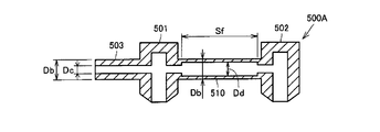
- FIG. 11 is a cross-sectional view corresponding to the arrow XX in FIG.
- the outer diameter of the first connecting tube 503 and the outer diameter of the second connecting tube 510 are the same outer diameter (Db), and the inner diameter (Dd) of the second connecting tube 510 is the same.
- the first connecting tube 503 is provided to be larger than the inner diameter dimension (Dc).
- the inner diameter dimension (Dd) of the second connection tube 510 is about 2.5 mm.
- the thickness of the second connection tube 510 becomes thinner than the thickness of the first connection tube 503, and the stress relaxation function (Sf) similar to that of the pressure sensor air tube 500 is achieved.
- Sf stress relaxation function
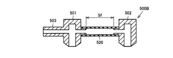
- Can be expected. 12 differs from the second connection tube 510 shown in FIG. 11 in that the second connection tube 520 is replaced by the first connection tube 503, the first air port connection head 501, and the second connection tube 510. It is configured by a different member that is more flexible than the airport connection head 502, and the dimensional relationship is the same as that of the second connection tube 510.
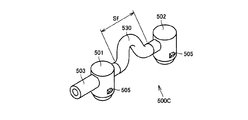
- This pressure sensor air tube 500 ⁇ / b> C employs a tube having a convex structure as the second connection tube 530.
- the second connection tube 530 can be expanded and contracted, and it is possible to expect the same stress relaxation function (Sf) as the pressure sensor air tube 500.
- This pressure sensor air tube 500D employs a bellows-type tube as the second connection tube 540.
- the second connecting tube 540 can be expanded and contracted, and a stress relaxation function (Sf) similar to that of the pressure sensor air tube 500 can be expected.
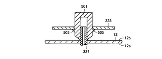
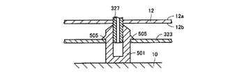
- FIGS. 9 and 15 to 17 The fixing structure of the pressure sensor air tubes 500A to 500D shown in FIGS. 11 to 14 is the same as the fixing structure of the pressure sensor air tube 500. Further, FIG. 15 is illustrated such that the front surface side of the internal substrate 12 is downward and the back surface side is upward.
- a first opening provided in the first shield plate 323 is formed on the outer surface of the first air port connection head 501 of the pressure sensor air tube 500 when the pressure sensor air tube 500 is connected to the first air port 327.
- a protruding member 505 that engages with the inner surface side of the first shield plate 323 is formed.
- a total of two protruding members 505 are provided at positions facing each other by 180 °.
- a second opening 326 provided in the second shield plate 324 has a second opening 326.
- a protruding member 505 that engages with the inner surface of the two shield plate 324 is formed.
- a total of two protruding members 505 are provided at positions facing each other by 180 °.
- the first air port connection head 501 and the second air port connection head 502 can adopt the same structure for the pressure sensor air tube 500 fixing structure. Only the fixing structure of the airport connection head 501 will be described.
- the protruding member 505 provided on the outer peripheral surface of the first air port connection head 501 is Overcoming the first shield plate 323 while elastically deforming, it is located inside the first shield plate 323.
- the first airport connection head 501 can be fixed to the first shield plate 323.
- the fixing of the first airport connection head 501 to the first shield plate 323 in the assembly process of the electronic sphygmomanometer 1 will be described.
- the first air port connection head 501 pressure sensor air tube
- the first air port connection head 501 is previously placed at a predetermined position of the main body 10.
- the internal substrate 12 is placed at a predetermined position of the main body 10 from above the first airport connection head 501.
- the first airport connection head 501 cannot be visually recognized by the operator. Since the first air port connection head 501 has elasticity, it can be said that the first air port connection head 501 can be fixed by pushing the first air port 327 into the first air port connection head 501. However, when the position of the first air port 327 is shifted, it is also conceivable that the internal substrate 12 is pressed against the main body 10 while the first air port connection head 501 is bent.
- the first shield plate 505 is elastically deformed while the projecting member 505 is elastically deformed.
- the operator can obtain a feeling of wearing that accompanies the restoration of the shape of the protruding member 505 when getting over the H.323 and positioning inside the first shield plate 323. Thereby, it becomes possible to confirm the connection of the first air port 327 to the first air port connection head 501 that cannot be visually recognized by the operator.
- a structure in which a protrusion member is provided on the air port connection head and engaged with the shield plate is adopted, but the present invention is not limited to this structure.
- a dedicated plate for engaging the protruding member can be provided on the internal substrate 12.
- the case where the protrusion members are provided at two locations on the outer peripheral surface of the airport connection head is described.
- the operator feels wearing feeling accompanying the restoration of the shape of the protrusion member.
- a configuration in which one protrusion member is provided on the outer peripheral surface of the air port connection head may be used.
- the case where the first air port connection head 501 and the second air port connection head 502 are provided to connect the two pressure sensors to the pressure sensor air tube 500 has been described.
- the configuration of the present embodiment can be adopted for one pressure sensor.
- the first pressure sensor 321 and the second pressure sensor 322 are arranged on the front surface side 12a of the internal substrate 12, and the pressure sensor air tube 500 is arranged on the back surface side 12b of the internal substrate 12.
- the first pressure sensor 321 and the second pressure sensor 322 are arranged on the back surface side 12b of the internal substrate 12, and the pressure sensor air tube 500 is arranged on the front surface side 12a of the internal substrate 12.
- the same effect can be obtained.
Landscapes
- Health & Medical Sciences (AREA)
- Life Sciences & Earth Sciences (AREA)
- Cardiology (AREA)
- Vascular Medicine (AREA)
- Biomedical Technology (AREA)
- Heart & Thoracic Surgery (AREA)
- Physiology (AREA)
- Biophysics (AREA)
- Pathology (AREA)
- Engineering & Computer Science (AREA)
- Veterinary Medicine (AREA)
- Physics & Mathematics (AREA)
- Medical Informatics (AREA)
- Molecular Biology (AREA)
- Surgery (AREA)
- Animal Behavior & Ethology (AREA)
- General Health & Medical Sciences (AREA)
- Public Health (AREA)
- Ophthalmology & Optometry (AREA)
- Measuring Pulse, Heart Rate, Blood Pressure Or Blood Flow (AREA)
Abstract
Description
図1は、この発明の実施の形態に係る電子血圧計1の外観を示す図である。図2は、本発明の実施の形態に係る電子血圧計のハードウェア構成を表わすブロック図である。図1および図2を参照して、電子血圧計1は、本体部10と、表カバー11と、被測定者の上腕に巻付け可能なカフ20とを備える。カフ20は、空気袋21を含む。表カバー11には、たとえば液晶などにより構成される表示部40と、ユーザ(被測定者)からの指示を受付けるための複数のスイッチからなる操作部41とが配置されている。
次に、図5から図7を参照して、第1圧力センサ321と第2圧力センサ322との配置構造について説明する。図5は、本実施の形態における電子血圧計1の本体部10から表カバー11を取り外した状態における内部構造を示す斜視図である。本実施の形態における電子血圧計1は、載置面Bに載置した状態において、表面カバー11が傾斜する構造を有している。
次に、図9から図14を参照して、圧力センサ用エアチューブの詳細構造について説明する。まず、図9および図10を参照して、図7に示す圧力センサ用エアチューブ500の詳細構造について説明する。
次に、図11を参照して、他の形態の圧力センサ用エアチューブ500Aの詳細構造について説明する。図11は、図9中のX-X線矢視に相当する断面図である。この圧力センサ用エアチューブ500Aは、第1連結チューブ503の外径と第2連結チューブ510の外径とは同じ外径寸法(Db)であり、第2連結チューブ510の内径寸法(Dd)が、第1連結チューブ503の内径寸法(Dc)よりも大きくなるように設けられている。具体的な寸法の一例としては、第2連結チューブ510の内径寸法(Dd)は約2.5mmである。
次に、図13を参照して、他の形態の圧力センサ用エアチューブ500Cの詳細構造について説明する。この圧力センサ用エアチューブ500Cは、第2連結チューブ530に凸形状構造のチューブを採用している。この構造を採用することで、第2連結チューブ530は伸縮可能となり、圧力センサ用エアチューブ500と同様の応力緩和機能(Sf)を期待することが可能となる。
次に、図14を参照して、他の形態の圧力センサ用エアチューブ500Dの詳細構造について説明する。この圧力センサ用エアチューブ500Dは、第2連結チューブ540に蛇腹構造のチューブを採用している。この構造を採用することで、第2連結チューブ540は伸縮可能となり、圧力センサ用エアチューブ500と同様の応力緩和機能(Sf)を期待することが可能となる。
次に、図9、および図15から図17を参照して、圧力センサ用エアチューブ500の固定構造について説明する。なお、図11から図14に示した圧力センサ用エアチューブ500A~500Dについての固定構造も、圧力センサ用エアチューブ500の固定構造と同じである。また、図15については、内部基板12の表面側が下方、裏面側が上方となるように図示している。
Claims (5)
- 測定部位に装着するカフ(20)と、
前記カフ(20)に加える圧力を調整する加圧・減圧装置(51)と、
圧力センサ(321,322)を含み、前記圧力センサ(321,322)から出力される圧力情報に基づき前記カフ内(20)のカフ圧を検出するための圧力検出装置(331,332)と、
前記圧力検出装置(331,332)が検出するカフ圧の変化に基づき血圧を算出する血圧算出装置(100)と、を備え、
前記圧力センサ(321,322)は、内部基板(12)の第1主面(12a)上に配設され、
前記圧力センサ(321,322)は、前記内部基板(12)の前記第1主面(12a)とは反対側の第2主面(12b)側に突出するエアポート(327,328)を有し、
前記エアポート(327,328)には、圧力センサ用エアチューブ(500)が連結され、
前記圧力センサ用エアチューブ(500)には、前記カフ(20)に連結するカフ用エアチューブ(31)から分岐する分岐エアチューブ(401)が連結され、
前記圧力センサ用エアチューブ(500)は、前記エアポート(327,328)に連結されるエアポート連結ヘッド(501)を有し、
前記エアポート連結ヘッド(501)と前記内部基板(12)との間には、前記エアポート連結ヘッド(501)を前記内部基板(12)に係合する係合領域(323,324,505)が設けられる、電子血圧計。 - 前記内部基板(12)は、前記第2主面(12b)側に前記エアポート(327,328)を露出させる開口部(325,326)が設けられ、前記第2主面(12b)から所定の間隙を隔てて配設されシールドプレート(323,324)を有し、
前記エアポート連結ヘッド(501)は、その外周面に前記エアポート(327,328)に連結される際に、前記開口部(326)において前記シールドプレート(323,324)の内面側に係合する、前記係合領域としての突起部材(505)を有する、請求の範囲第1項に記載の電子血圧計。 - 前記突起部材(504,505)は、前記エアポート連結ヘッド(501)の外側面に2以上設けられる、請求の範囲第2項に記載の電子血圧計。
- 前記圧力センサとして、第1圧力センサ(321)および第2圧力センサ(322)を有し、
前記圧力検出装置(331,332)は、前記第1圧力センサ(321)および前記第2圧力センサ(322)から出力される圧力情報に基づき前記カフ内(20)のカフ圧を検出し、
前記エアポートとして、前記第1圧力センサ(321)の第1エアポート(327)と、前記第2圧力センサ(322)の第2エアポート(328)とを有し、
前記内部基板(12)は、前記第2主面(12b)側に前記第1エアポート(327)を露出させる第1開口部(325)が設けられ、前記第2主面(12b)から所定の間隙を隔てて配設された第1シールドプレート(323)と、前記第2主面(12b)側に前記第2エアポート(328)を露出させる第2開口部(326)が設けられ、前記第2主面(12b)から所定の間隙を隔てて配設された第2シールドプレート(324)とを有し、
前記圧力センサ用エアチューブ(500)は、前記第1エアポート(327)に連結される第1エアポート連結ヘッド(501)と、前記第2エアポート(328)に連結される第2エアポート連結ヘッド(502)とを有し、
前記第1エアポート連結ヘッド(501)は、その外周面に前記第1エアポート(327)に連結される際に、前記第1開口部(326)において前記第1シールドプレート(323)の内面側に係合する、前記突起部材(505)を有し、
前記第2エアポート連結ヘッド(502)は、その外周面に前記第2エアポート(328)に連結される際に、前記第2開口部(327)において前記第2シールドプレート(324)の内面側に係合する、前記突起部材(505)を有する、請求の範囲第2項に記載の電子血圧計。 - 前記突起部材(504,505)は、前記エアポート連結ヘッド(501)の外側面に2以上設けられる、請求の範囲第4項に記載の電子血圧計。
Priority Applications (5)
| Application Number | Priority Date | Filing Date | Title |
|---|---|---|---|
| DE112010004395.7T DE112010004395B4 (de) | 2009-11-13 | 2010-11-10 | Elektronisches Blutdruckmessgerät |
| RU2012124100/14A RU2551138C2 (ru) | 2009-11-13 | 2010-11-10 | Электронный сфигмоманометр |
| CN201080050227.7A CN102753089B (zh) | 2009-11-13 | 2010-11-10 | 电子血压计 |
| BR112012011417-4A BR112012011417B1 (pt) | 2009-11-13 | 2010-11-10 | Esfigmomanômetro eletrônico |
| US13/468,239 US8998819B2 (en) | 2009-11-13 | 2012-05-10 | Electronic sphygmomanometer |
Applications Claiming Priority (2)
| Application Number | Priority Date | Filing Date | Title |
|---|---|---|---|
| JP2009-259917 | 2009-11-13 | ||
| JP2009259917A JP5195722B2 (ja) | 2009-11-13 | 2009-11-13 | 電子血圧計 |
Related Child Applications (1)
| Application Number | Title | Priority Date | Filing Date |
|---|---|---|---|
| US13/468,239 Continuation US8998819B2 (en) | 2009-11-13 | 2012-05-10 | Electronic sphygmomanometer |
Publications (1)
| Publication Number | Publication Date |
|---|---|
| WO2011059005A1 true WO2011059005A1 (ja) | 2011-05-19 |
Family
ID=43991663
Family Applications (1)
| Application Number | Title | Priority Date | Filing Date |
|---|---|---|---|
| PCT/JP2010/070035 Ceased WO2011059005A1 (ja) | 2009-11-13 | 2010-11-10 | 電子血圧計 |
Country Status (7)
| Country | Link |
|---|---|
| US (1) | US8998819B2 (ja) |
| JP (1) | JP5195722B2 (ja) |
| CN (1) | CN102753089B (ja) |
| BR (1) | BR112012011417B1 (ja) |
| DE (1) | DE112010004395B4 (ja) |
| RU (1) | RU2551138C2 (ja) |
| WO (1) | WO2011059005A1 (ja) |
Families Citing this family (4)
| Publication number | Priority date | Publication date | Assignee | Title |
|---|---|---|---|---|
| TWI558373B (zh) * | 2014-05-08 | 2016-11-21 | 凱健企業股份有限公司 | 電子血壓計之顯示方法 |
| USD802768S1 (en) * | 2016-02-08 | 2017-11-14 | Welch Allyn, Inc. | Medical device |
| JP6750294B2 (ja) * | 2016-04-28 | 2020-09-02 | オムロンヘルスケア株式会社 | 脈波検出装置、及び、生体情報測定装置 |
| CN108888252A (zh) * | 2018-05-03 | 2018-11-27 | 谢娟 | 一种医用血压测量装置 |
Citations (1)
| Publication number | Priority date | Publication date | Assignee | Title |
|---|---|---|---|---|
| JPH0360635A (ja) * | 1989-07-29 | 1991-03-15 | Terumo Corp | 血圧計 |
Family Cites Families (14)
| Publication number | Priority date | Publication date | Assignee | Title |
|---|---|---|---|---|
| EP0329806B1 (en) * | 1988-02-25 | 1990-10-03 | Hewlett-Packard GmbH | Blood pressure monitor and pneumatic connector therefor |
| DE3861517D1 (de) | 1988-05-14 | 1991-02-14 | Hewlett Packard Gmbh | Blutdruckueberwacher. |
| JP2507031Y2 (ja) * | 1990-07-03 | 1996-08-14 | シチズン時計株式会社 | 血圧計用定速排気調節装置 |
| JP3178175B2 (ja) | 1993-08-11 | 2001-06-18 | オムロン株式会社 | 電子血圧計 |
| JP3363261B2 (ja) | 1994-06-27 | 2003-01-08 | 松下電工株式会社 | 血圧計 |
| CN2314735Y (zh) * | 1997-11-28 | 1999-04-21 | 叶健和 | 血压计的排气降压结构 |
| US6168567B1 (en) * | 1998-07-09 | 2001-01-02 | Accusphyg, Llc | Hybrid sphygmomanometer |
| DE20005324U1 (de) | 2000-03-22 | 2000-05-31 | Health & Life Co., Ltd., Chung-Ho | Instrument zur Blutdruckmessung |
| RU2190345C2 (ru) * | 2000-10-24 | 2002-10-10 | Борис Иосифович Синельников | Устройство для измерения артериального давления крови |
| JP4062614B2 (ja) * | 2003-06-11 | 2008-03-19 | 株式会社エー・アンド・デイ | 血圧計用エアソケットおよび電子血圧計 |
| US8454521B2 (en) * | 2004-09-10 | 2013-06-04 | Terumo Kabushiki Kaisha | Sphygmomanometer |
| JP4687323B2 (ja) * | 2005-08-12 | 2011-05-25 | オムロンヘルスケア株式会社 | 血圧計測装置 |
| CN2910109Y (zh) * | 2005-12-14 | 2007-06-13 | 李哲英 | 基于波形特征识别的电子血压计 |
| CN100546537C (zh) | 2006-07-11 | 2009-10-07 | 深圳迈瑞生物医疗电子股份有限公司 | 一种无创血压测量装置及其安全保护方法 |
-
2009
- 2009-11-13 JP JP2009259917A patent/JP5195722B2/ja active Active
-
2010
- 2010-11-10 CN CN201080050227.7A patent/CN102753089B/zh active Active
- 2010-11-10 WO PCT/JP2010/070035 patent/WO2011059005A1/ja not_active Ceased
- 2010-11-10 DE DE112010004395.7T patent/DE112010004395B4/de active Active
- 2010-11-10 BR BR112012011417-4A patent/BR112012011417B1/pt active IP Right Grant
- 2010-11-10 RU RU2012124100/14A patent/RU2551138C2/ru active
-
2012
- 2012-05-10 US US13/468,239 patent/US8998819B2/en active Active
Patent Citations (1)
| Publication number | Priority date | Publication date | Assignee | Title |
|---|---|---|---|---|
| JPH0360635A (ja) * | 1989-07-29 | 1991-03-15 | Terumo Corp | 血圧計 |
Also Published As
| Publication number | Publication date |
|---|---|
| CN102753089A (zh) | 2012-10-24 |
| BR112012011417A2 (pt) | 2016-05-03 |
| BR112012011417A8 (pt) | 2019-11-26 |
| RU2551138C2 (ru) | 2015-05-20 |
| BR112012011417B1 (pt) | 2021-07-13 |
| US8998819B2 (en) | 2015-04-07 |
| RU2012124100A (ru) | 2013-12-20 |
| JP5195722B2 (ja) | 2013-05-15 |
| CN102753089B (zh) | 2014-12-03 |
| US20120226169A1 (en) | 2012-09-06 |
| DE112010004395T5 (de) | 2013-01-03 |
| JP2011103982A (ja) | 2011-06-02 |
| DE112010004395B4 (de) | 2024-05-08 |
Similar Documents
| Publication | Publication Date | Title |
|---|---|---|
| JP5141666B2 (ja) | 電子血圧計 | |
| JP5195723B2 (ja) | 電子血圧計 | |
| CN102143705B (zh) | 提高测定值的可靠性的电子血压计 | |
| JP5152153B2 (ja) | 電子血圧計 | |
| US9326692B2 (en) | Blood pressure measurement device and blood pressure measurement method | |
| US6290650B1 (en) | Tonometry system for monitoring blood pressure | |
| JP5375538B2 (ja) | 電子血圧計 | |
| WO2012014614A1 (ja) | 電子血圧計用モジュールおよび電子血圧計 | |
| JP2011507557A (ja) | 大腿部圧迫装置 | |
| KR20050117825A (ko) | 혈압계 및 이를 이용한 혈압측정방법 | |
| JP5195722B2 (ja) | 電子血圧計 | |
| JP6658332B2 (ja) | 血圧計 | |
| JP4029426B2 (ja) | 血流診断装置 | |
| JP3163340U (ja) | 電子血圧計用モジュールおよび電子血圧計 |
Legal Events
| Date | Code | Title | Description |
|---|---|---|---|
| WWE | Wipo information: entry into national phase |
Ref document number: 201080050227.7 Country of ref document: CN |
|
| 121 | Ep: the epo has been informed by wipo that ep was designated in this application |
Ref document number: 10829964 Country of ref document: EP Kind code of ref document: A1 |
|
| WWE | Wipo information: entry into national phase |
Ref document number: 112010004395 Country of ref document: DE Ref document number: 1120100043957 Country of ref document: DE |
|
| WWE | Wipo information: entry into national phase |
Ref document number: 5054/CHENP/2012 Country of ref document: IN |
|
| WWE | Wipo information: entry into national phase |
Ref document number: 2012124100 Country of ref document: RU |
|
| 122 | Ep: pct application non-entry in european phase |
Ref document number: 10829964 Country of ref document: EP Kind code of ref document: A1 |
|
| REG | Reference to national code |
Ref country code: BR Ref legal event code: B01A Ref document number: 112012011417 Country of ref document: BR |
|
| ENP | Entry into the national phase |
Ref document number: 112012011417 Country of ref document: BR Kind code of ref document: A2 Effective date: 20120514 |