WO2011052265A1 - バイオマスガス化システム及びバイオマスガス化方法 - Google Patents
バイオマスガス化システム及びバイオマスガス化方法 Download PDFInfo
- Publication number
- WO2011052265A1 WO2011052265A1 PCT/JP2010/060900 JP2010060900W WO2011052265A1 WO 2011052265 A1 WO2011052265 A1 WO 2011052265A1 JP 2010060900 W JP2010060900 W JP 2010060900W WO 2011052265 A1 WO2011052265 A1 WO 2011052265A1
- Authority
- WO
- WIPO (PCT)
- Prior art keywords
- biomass
- gas
- gasification
- gas purification
- purification means
- Prior art date
- Legal status (The legal status is an assumption and is not a legal conclusion. Google has not performed a legal analysis and makes no representation as to the accuracy of the status listed.)
- Ceased
Links
Images





Classifications
-
- C—CHEMISTRY; METALLURGY
- C10—PETROLEUM, GAS OR COKE INDUSTRIES; TECHNICAL GASES CONTAINING CARBON MONOXIDE; FUELS; LUBRICANTS; PEAT
- C10J—PRODUCTION OF PRODUCER GAS, WATER-GAS, SYNTHESIS GAS FROM SOLID CARBONACEOUS MATERIAL, OR MIXTURES CONTAINING THESE GASES; CARBURETTING AIR OR OTHER GASES
- C10J3/00—Production of combustible gases containing carbon monoxide from solid carbonaceous fuels
-
- C—CHEMISTRY; METALLURGY
- C10—PETROLEUM, GAS OR COKE INDUSTRIES; TECHNICAL GASES CONTAINING CARBON MONOXIDE; FUELS; LUBRICANTS; PEAT
- C10J—PRODUCTION OF PRODUCER GAS, WATER-GAS, SYNTHESIS GAS FROM SOLID CARBONACEOUS MATERIAL, OR MIXTURES CONTAINING THESE GASES; CARBURETTING AIR OR OTHER GASES
- C10J3/00—Production of combustible gases containing carbon monoxide from solid carbonaceous fuels
- C10J3/46—Gasification of granular or pulverulent flues in suspension
- C10J3/48—Apparatus; Plants
- C10J3/482—Gasifiers with stationary fluidised bed
-
- C—CHEMISTRY; METALLURGY
- C10—PETROLEUM, GAS OR COKE INDUSTRIES; TECHNICAL GASES CONTAINING CARBON MONOXIDE; FUELS; LUBRICANTS; PEAT
- C10J—PRODUCTION OF PRODUCER GAS, WATER-GAS, SYNTHESIS GAS FROM SOLID CARBONACEOUS MATERIAL, OR MIXTURES CONTAINING THESE GASES; CARBURETTING AIR OR OTHER GASES
- C10J3/00—Production of combustible gases containing carbon monoxide from solid carbonaceous fuels
- C10J3/72—Other features
- C10J3/82—Gas withdrawal means
- C10J3/84—Gas withdrawal means with means for removing dust or tar from the gas
-
- C—CHEMISTRY; METALLURGY
- C10—PETROLEUM, GAS OR COKE INDUSTRIES; TECHNICAL GASES CONTAINING CARBON MONOXIDE; FUELS; LUBRICANTS; PEAT
- C10K—PURIFYING OR MODIFYING THE CHEMICAL COMPOSITION OF COMBUSTIBLE GASES CONTAINING CARBON MONOXIDE
- C10K1/00—Purifying combustible gases containing carbon monoxide
- C10K1/02—Dust removal
-
- C—CHEMISTRY; METALLURGY
- C10—PETROLEUM, GAS OR COKE INDUSTRIES; TECHNICAL GASES CONTAINING CARBON MONOXIDE; FUELS; LUBRICANTS; PEAT
- C10K—PURIFYING OR MODIFYING THE CHEMICAL COMPOSITION OF COMBUSTIBLE GASES CONTAINING CARBON MONOXIDE
- C10K1/00—Purifying combustible gases containing carbon monoxide
- C10K1/20—Purifying combustible gases containing carbon monoxide by treating with solids; Regenerating spent purifying masses
-
- C—CHEMISTRY; METALLURGY
- C10—PETROLEUM, GAS OR COKE INDUSTRIES; TECHNICAL GASES CONTAINING CARBON MONOXIDE; FUELS; LUBRICANTS; PEAT
- C10K—PURIFYING OR MODIFYING THE CHEMICAL COMPOSITION OF COMBUSTIBLE GASES CONTAINING CARBON MONOXIDE
- C10K1/00—Purifying combustible gases containing carbon monoxide
- C10K1/20—Purifying combustible gases containing carbon monoxide by treating with solids; Regenerating spent purifying masses
- C10K1/30—Purifying combustible gases containing carbon monoxide by treating with solids; Regenerating spent purifying masses with moving purifying masses
-
- B—PERFORMING OPERATIONS; TRANSPORTING
- B01—PHYSICAL OR CHEMICAL PROCESSES OR APPARATUS IN GENERAL
- B01D—SEPARATION
- B01D2257/00—Components to be removed
- B01D2257/30—Sulfur compounds
- B01D2257/304—Hydrogen sulfide
-
- B—PERFORMING OPERATIONS; TRANSPORTING
- B01—PHYSICAL OR CHEMICAL PROCESSES OR APPARATUS IN GENERAL
- B01D—SEPARATION
- B01D2258/00—Sources of waste gases
- B01D2258/05—Biogas
-
- C—CHEMISTRY; METALLURGY
- C10—PETROLEUM, GAS OR COKE INDUSTRIES; TECHNICAL GASES CONTAINING CARBON MONOXIDE; FUELS; LUBRICANTS; PEAT
- C10J—PRODUCTION OF PRODUCER GAS, WATER-GAS, SYNTHESIS GAS FROM SOLID CARBONACEOUS MATERIAL, OR MIXTURES CONTAINING THESE GASES; CARBURETTING AIR OR OTHER GASES
- C10J2300/00—Details of gasification processes
- C10J2300/09—Details of the feed, e.g. feeding of spent catalyst, inert gas or halogens
- C10J2300/0913—Carbonaceous raw material
- C10J2300/0916—Biomass
-
- C—CHEMISTRY; METALLURGY
- C10—PETROLEUM, GAS OR COKE INDUSTRIES; TECHNICAL GASES CONTAINING CARBON MONOXIDE; FUELS; LUBRICANTS; PEAT
- C10J—PRODUCTION OF PRODUCER GAS, WATER-GAS, SYNTHESIS GAS FROM SOLID CARBONACEOUS MATERIAL, OR MIXTURES CONTAINING THESE GASES; CARBURETTING AIR OR OTHER GASES
- C10J2300/00—Details of gasification processes
- C10J2300/18—Details of the gasification process, e.g. loops, autothermal operation
- C10J2300/1807—Recycle loops, e.g. gas, solids, heating medium, water
-
- Y—GENERAL TAGGING OF NEW TECHNOLOGICAL DEVELOPMENTS; GENERAL TAGGING OF CROSS-SECTIONAL TECHNOLOGIES SPANNING OVER SEVERAL SECTIONS OF THE IPC; TECHNICAL SUBJECTS COVERED BY FORMER USPC CROSS-REFERENCE ART COLLECTIONS [XRACs] AND DIGESTS
- Y02—TECHNOLOGIES OR APPLICATIONS FOR MITIGATION OR ADAPTATION AGAINST CLIMATE CHANGE
- Y02E—REDUCTION OF GREENHOUSE GAS [GHG] EMISSIONS, RELATED TO ENERGY GENERATION, TRANSMISSION OR DISTRIBUTION
- Y02E50/00—Technologies for the production of fuel of non-fossil origin
- Y02E50/30—Fuel from waste, e.g. synthetic alcohol or diesel
Definitions
- the present invention relates to a biomass gasification system and a biomass gasification method.
- biomass refers to organisms such as agricultural products or by-products, wood, and plants. Since they are grown by the action of sunlight, air, water, soil, etc., they can be produced indefinitely. Moreover, since the biomass absorbs carbon dioxide from the atmosphere by photosynthesis during the growth process, producing the biomass also leads to a reduction in the amount of carbon dioxide in the atmosphere. For these reasons, a biomass gasification technique that gasifies the biomass to produce a gas for fuel is known as a technique preferable for the global environment.
- the gas produced using the biomass as a raw material includes gasification char, tar, hydrogen sulfide, etc., it is used as it is for gas turbines and fuel cells, and as a catalyst for highly purifying the gas. Not suitable for introduction. For this reason, conventionally, it has been devised to remove the gasification char, tar, hydrogen sulfide and the like by a dust removing device and a gas purifying device.
- biomass supply means for supplying biomass into the furnace body, and oxidant supply for supplying combustion oxidant made of oxygen or a mixture of oxygen and water vapor into the furnace body
- a biomass gasification furnace comprising: means; a dust removing device that removes dust from the product gas gasified in the biomass gasification furnace; a cooler that cools the dust-removed gas; and the purified gas is purified.
- a biomass gasification system including a gas purification unit is disclosed.
- the gas purification means for the biomass gasification gas temporarily holds the biomass, and the cooled product gas that has passed through the cooler is passed through the gas purification unit, where tar components contained in the cooled product gas are passed.
- the tar adsorbed biomass adsorbed and used as purified gas and adsorbed with the tar component is conveyed to the biomass supplying means by the conveying means.
- JP 2004-346285 A (paragraphs 0047, 0048, FIG. 1, etc.)
- JP 2008-24752 A (paragraph 0017, FIG. 1, etc.)
- the concentration of tar contained in the refined gas is high, and is used for gas turbines, fuel cells, and the like, and the gas is introduced into a highly purified catalyst. Had the problem of insufficient purification.
- the concentration of H 2 S contained in the purified gas is also used in a gas turbine, a fuel cell, etc., and as a catalyst for highly purifying the gas. It was a problem when introducing it.
- the present invention was made in view of the above, biomass reduces at least one of the tar components or H 2 S concentration in the gas of the gas produced by the gasification, to improve the purity of the purified gas It is an object of the present invention to provide a biomass gasification system and method capable of performing the above.
- the present invention removes a biomass gasification furnace that gasifies biomass and a gasification char contained in the gasification gas generated in the biomass gasification furnace.
- a gas refining means for purifying the gasified gas from which the gasification char has been removed by the dust removing apparatus to be a purified gas comprising: biomass supplied to a biomass gasification furnace; A porous particle having pores therein, and a gasified gas introduction section for introducing a gasified gas from which gasified char has been removed by the dust removing device into the gas purification means; and the biomass and the pores.
- a purified gas discharge section for discharging purified gas that has passed through the porous particles.
- the gas purification means in addition to the adsorption of the tar component in the gasified gas dedusted by the biomass, the porous particles having the pores are also contained in the gasified gas. Since at least the tar component can be adsorbed, the tar component in the generated gasification gas can be reduced, and the purity of the purified gas can be improved.
- the present invention is characterized in that, in the above-mentioned invention, a filter is provided downstream of the purified gas outlet of the gas purifying means and captures impurities contained in the purified gas. According to the present invention, by providing the filter, it is possible to capture and remove tar components and the like in the purified gas that could not be removed by the gas purification means. Can be improved.
- the present invention is characterized in that, in the above-mentioned invention, biomass processing means is provided for heat-treating or steam-treating biomass supplied to the gas purification means.
- biomass processing means is provided for heat-treating or steam-treating biomass supplied to the gas purification means.
- the biomass treatment means by providing the biomass treatment means, the biomass is heat-treated or steam-treated, and the pores of the biomass grow, so that the tar adsorption capacity in the gas purification means is improved, and the purified gas Purity can be improved.
- the heat or steam used for the heat treatment or steam treatment in the biomass treatment means uses plant waste heat or surplus steam. Since there is no need to newly provide a heating means, the cost for introducing the heating means can be reduced, and the power for operating the heating means can be omitted, so that the plant efficiency is improved. is there.
- the present invention in the above invention, the gas purification means, and providing a H 2 S adsorbent supplying means for supplying H 2 S adsorbent for removing H 2 S from the gasification gas.
- a H 2 S adsorbent supplying means for supplying to the gas purification unit, H in the gas purification means 2 S adsorption ability is improved, and the purity of the purified gas can be improved.
- the H 2 S adsorbent includes, for example, CaO, CaCo 3 , and CaSO 4 adsorbents as Ca-based adsorbents that can adsorb H 2 S. More preferably, as an inexpensive material, for example, a Ca / Si material such as a by-product of cement is used. If the H 2 S adsorbent supplied periodically is inexpensive, the cost for operation can be reduced.
- the present invention is the above invention, wherein the filter is a filter holding activated carbon that captures a tar component contained in the purified gas, and the porous particles are destroyed by capturing the tar component by the activated carbon. Characterized by activated carbon particles after fracture.
- the filter is a filter holding activated carbon that captures a tar component contained in the purified gas, and the porous particles are destroyed by capturing the tar component by the activated carbon. Characterized by activated carbon particles after fracture.
- the filter is a filter holding activated carbon that captures a tar component contained in the purified gas, and the porous particles are destroyed by capturing the tar component by the activated carbon. Characterized by activated carbon particles after fracture.
- the upper limit of the amount by which activated carbon can adsorb tar depends on the tar concentration. That is, if the tar concentration is low, the upper limit of the amount that can adsorb tar is small, and if the tar concentration is high, the upper limit of the amount that can adsorb tar is large. Therefore, since the tar concentration in the purified gas that has passed through the gas purification means is higher than the tar concentration in the gasification gas that has passed through the gas purification means, the tar in the purified gas is adsorbed. Even if the activated carbon is broken, further tar adsorption is possible at a high tar concentration in the gasification gas. Furthermore, it is not necessary to treat activated carbon after the rupture, which is conventionally required separately, and the treatment cost can be reduced.
- the present invention is the gasification char supply path for supplying the gasification char removed by the dust removal device to the gas purification means in the above invention, wherein the porous particles are the gasification char removed by the dust removal device. It is characterized by providing.
- the gasification char supply path for supplying the gasification char removed by the dust removing device to the gas purification means, the adsorption capacity of the tar component and H 2 S in the gas purification means is improved. improves. This is because the gasification char in the gasification gas generated in the biomass gasification furnace contains unburned components, has a large surface area, and a large tar adsorption capacity. In addition, since the gasification char has micropores capable of adsorbing H 2 S and contains a large amount of alkali components such as Ca, it can effectively adsorb H 2 S.
- the gas purification means functions to suppress scattering of the gasification char in which the biomass is fine powder. As a result, it is possible to prevent scattered ash from being contained in the purified gas discharged from the gas purification means, and to improve the purity of the purified gas.
- the present invention is characterized in that, in the above invention, a steam supply means for supplying steam is provided in the gasification char supply path.
- a steam supply means for supplying steam is provided in the gasification char supply path.
- the gasification char is steam-treated, and the growth of pores of the gasification char is promoted to improve the tar adsorption ability of the gasification char. Can do. Therefore, the tar adsorption capacity in the gas purification means is improved, and the purity of the purified gas can be improved.
- the gasification char supply path holds an inert gas supply means for supplying an inert gas for transporting the gasification char, and biomass supplied to the gas purification means,
- the gasification char is introduced, and the biomass hopper replaces the air contained in the biomass with the inert gas for gasification char conveyance.
- the present invention by providing the biomass hopper, before supplying biomass containing air to the gas purification means, the inert gas used for transporting the gasification char, and the biomass hopper Since the air contained in the biomass can be replaced, it is possible to prevent unexpected combustion in the gas refining means, and it is not necessary to newly provide an inert gas supply means or its route, thus simplifying the system. In addition, an increase in plant operating efficiency can be expected.
- the present invention in the above invention, has a plurality of the gas purification means, the purification gas discharge part of the upstream gas purification means, and the gasification of the gas purification means downstream of the upstream gas purification means
- a purified gas supply path that communicates with the gas inlet is provided.
- the gasification char held in the gas purification means has a plurality of pores, and each pore first has a macropore from the surface, and has a plurality of micropores at the tip. .
- the gasification gas from which the gasification char has been removed by the dust removing device is adsorbed in the gas purification means by the tar components in the gasification gas in the macropores of the gasification char, and in the micropores of the gasification char.
- H 2 S in the gasified gas is adsorbed.
- the gasification char after adsorbing the tar component becomes difficult to adsorb H 2 S in the micropores as a result of the micropores being blocked.
- the adsorption of H 2 S in the chemical gas becomes insufficient.
- a plurality of the gas purification means are provided, and the tar component in the gasification gas is adsorbed by the macropores of the gasification char and the biomass in the upper gas purification means.
- the gasification gas from which the tar component has been removed in the upper gas purification means is introduced into the lower gas purification means, and the micropores of the gasification char held in the lower gas purification means Can adsorb H 2 S in the gasification gas. Therefore, the adsorption capacity of the tar component and H 2 S in the gas purification means is improved.
- the present invention is characterized in that, in the above invention, a filter for holding activated carbon that captures a tar component contained in the purified gas is provided downstream of the purified gas at the outlet of the purified gas.
- a filter for holding activated carbon downstream of the purified gas outlet of the gas purification means, tar components and the like in the purified gas that could not be removed by the gas purification means. Can be adsorbed and removed.
- the gas purification means even when the gasification char is scattered and the gasification char is contained in the purification gas, the gasification char is captured and removed by providing the filter. It becomes possible.
- the present invention is characterized in that, in the above-mentioned invention, the gas purification means is provided with activated carbon particle supplying means after breaking to supply activated carbon particles after breaking which the activated carbon broke by capturing a tar component.
- the adsorption ability of the tar component in the gasification gas in the gas purification means can be improved.
- the upper limit of the amount by which activated carbon can adsorb tar depends on the tar concentration. That is, if the tar concentration is low, the upper limit of the amount that can adsorb tar is small, and if the tar concentration is high, the upper limit of the amount that can adsorb tar is large. Therefore, since the tar concentration in the purified gas that has passed through the gas purification means is higher than the tar concentration in the gasification gas that has passed through the gas purification means, the tar in the purified gas is adsorbed. Even if the activated carbon is broken, tar adsorption is possible at a high tar concentration in the gasification gas. Furthermore, it is not necessary to treat activated carbon after the rupture, which is conventionally required separately, and the treatment cost can be reduced.
- the present invention includes a step of gasifying biomass in a biomass gasification furnace, a step of removing gasification char in the gasification gas generated in the biomass gasification furnace with a dust removal device, and a biomass and the dust removal device inside. And a step of purifying the gasification gas through the gas purification means holding the removed gasification char through the gasification gas from which the gasification char has been removed by the dust removing device.
- the gasification char in the gasification gas produced in the biomass gasification furnace contains unburned components, has a large surface area, and a large tar adsorption capacity. Moreover, since the gasification char has micropores capable of adsorbing H 2 S and contains a large amount of alkali components such as Ca, it can effectively adsorb H 2 S. Therefore, according to the present invention, by passing the gasified gas from which the ash has been removed by the dust removing device through the gas purifying device in which the gasified char removed by the dust removing device is held together with the biomass, The adsorption capacity of the tar component and H 2 S in the is improved.
- the biomass since the biomass is held in the gas purification means, the biomass functions to suppress scattering of the gasification char that is fine powder. As a result, it is possible to prevent the purified gas discharged from the gas purification means from containing scattered gasification char. Therefore, the purity of the purified gas can be improved.
- the present invention includes a step of gasifying biomass in a biomass gasification furnace, a step of removing gasification char in the gasification gas generated in the biomass gasification furnace with a dust removing device, and biomass and activated carbon particles after demolition inside
- a step of purifying the gasification gas through the gas purification means in which the gasification char has been removed by the dust removing device and the activated carbon provided downstream of the purified gas outlet of the gas purification means Passing the purified gas through a filter holding the purified gas, and purifying the purified gas, and supplying the activated carbon particles after destruction by capturing the tar component to the gas purification means.
- the purification that could not be removed by the gas purification means by passing the purified gas through a filter that holds the activated carbon provided downstream of the purified gas outlet of the gas purification means.
- a tar component or the like in the gas can be adsorbed and removed.
- the gasification in the gas purification means The adsorption ability of the tar component in the gas can be improved.
- the upper limit of the amount by which activated carbon can adsorb tar depends on the tar concentration. That is, if the tar concentration is low, the upper limit of the amount that can adsorb tar is small, and if the tar concentration is high, the upper limit of the amount that can adsorb tar is large. Therefore, since the tar concentration in the purified gas that has passed through the gas purification means is higher than the tar concentration in the gasification gas that has passed through the gas purification means, the tar in the purified gas is adsorbed. Even if the activated carbon is broken, tar adsorption is possible at a high tar concentration in the gasification gas. Furthermore, it is not necessary to treat activated carbon after the rupture, which is conventionally required separately, and the treatment cost can be reduced.
- the biomass gasification system and the biomass gasification method according to the present invention improve the purity of purified gas by reducing at least one of a tar component or H 2 S concentration in a gasification gas generated by gasifying biomass. There is an effect that can be.
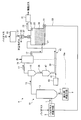
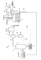
- FIG. 1 is a diagram illustrating an outline of a biomass gasification system according to a first embodiment.
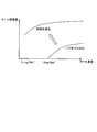
- FIG. 2 is a graph showing the relationship between the tar concentration in the gasification gas after passing through the gas purification means and the amount of tar adsorbed by the gas purification means.
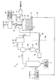
- FIG. 3 is a diagram illustrating an outline of the biomass gasification system according to the second embodiment.
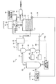
- FIG. 4 is a diagram illustrating an outline of the biomass gasification system according to the third embodiment.
- FIG. 5 is a diagram illustrating an outline of the biomass gasification system according to the fourth embodiment.
- FIG. 6 is a diagram illustrating an outline of the biomass gasification system according to the fifth embodiment.
- FIG. 7 is a diagram illustrating an outline of the biomass gasification system according to the sixth embodiment.
- FIG. 1 is a diagram illustrating an outline of a biomass gasification system according to a first embodiment.
- FIG. 2 is a graph showing the relationship between the tar concentration in the gasification gas after passing through the gas purification means and
- FIG. 8 is a diagram showing the structure of the pores of the gasification char.
- FIG. 9 is a diagram illustrating an outline of the biomass gasification system according to the seventh embodiment.
- FIG. 10 is a graph showing the relationship between the tar concentration in the gas and the amount of tar adsorbed by activated carbon.
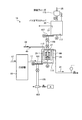
- FIG. 11 is a diagram illustrating an outline of the biomass gasification system according to the eighth embodiment.
- FIG. 1 is a diagram illustrating an outline of a biomass gasification system according to a first embodiment.
- the biomass gasification system 2 according to the first embodiment includes a biomass supply means 5 that supplies biomass 1 into the furnace body 3, and a combustion oxidant that includes oxygen or a mixture of oxygen and water vapor.
- a biomass gasification furnace 11 provided with an oxidant supply means 9 for supplying 7 into the furnace body 3, a cyclone for removing the gasification char 39 in the gasification gas 13 gasified in the biomass gasification furnace 11, etc.
- a cooler 19 for cooling the dusted gasified gas 17, a gas purifying means 23 that purifies the gasified gas 17 into a purified gas 21, and a purified gas 21 purified by the gas purifying means 23.
- a filter 31 for further purification.
- the cooler 19 for example, a system in which water is indirectly contacted with the gasification gas 17 to exchange heat can be used.
- this type of cooler one designed so that water vapor is generated by heat exchange can be used.
- the generated water vapor may be supplied to the oxidant supply means 9 through the water vapor supply path 19 a and used as a part of the oxidant 7.
- the gas purification means 23 holds the biomass 25 and porous particles having pores therein, and also introduces a gasification gas introduction section 27 for introducing the gasification gas 17 into the gas purification means 23, the biomass 25 and the pores And a purified gas discharge portion 29 for discharging the purified gas 21 that has been purified through the porous particles.
- the biomass gasification system 2 is provided with a biomass hopper 35 that supplies the biomass 25 to the gas purification means 23, and the biomass hopper 35 is provided with an inert gas outlet 37 that discharges the inert gas.
- This inert gas reduces the concentration of the air that is embraced while the biomass 25 is supplied to the biomass hopper 35, and when the biomass 25 is supplied to the gas purification means 23, the air and the gasified gas 17 are reduced. Used to prevent unexpected combustion due to contact.
- the inert gas is supplied from an inert gas supply means for biomass (for example, one comprising a cylinder for storing inert gas and a cylinder for discharging the inert gas to the outside of the cylinder), biomass hopper 35 or biomass. 25 transport gas is supplied upstream of the biomass hopper 35.
- the inert gas supply means for biomass is an inert gas supply means 43 that supplies an inert gas 41 for transporting the gasification char 39, and the inert gas 41 is supplied to the gasification char supply path 45. It may be branched and supplied before being processed. In this way, the introduction cost and the like can be reduced as compared with the case where an inert gas supply means is newly provided. Further, in order to discharge the inert gas and air from the biomass hopper 35 downstream of the inert gas discharge port 37, an inert gas discharge means such as a suction blower is provided.
- the biomass 25 may be the same as the biomass 1 supplied to the furnace body 3, and is obtained by pulverizing and drying the produced or discarded biomass.
- Biomass refers to organisms such as agricultural products or by-products, wood, and plants, and for example, sweet sorghum, napiergrass, spirulina and the like are used.
- the porous material having the pores held together with the biomass 25 inside the gas purification means 23 is the gasification char 39 separated by the dust removing device 15.
- the gas purification means 49 including the biomass 25 and the gasification char 39 is held in the gas purification means 23 in the biomass gasification system 2.
- the biomass gasification system 2 includes a gasification char supply path 45 that communicates the dust removing device 15 and the gas purification means 23, and an inert gas 41 for transporting the gasification char 39 to the gas purification means 23.
- An inert gas supply means 43 for supplying to the chemical char supply path 45 is provided.
- the gasification char supply path 45 is provided with a gasification char hopper 47 for temporarily holding the gasification char 39.
- a gas purification material discharge means 51 for discharging the gas purification material 49 inside the gas purification means 23 is provided at the lower part of the gas purification means 23, and the discharged The gas purification material 49 is conveyed by the gas purification material conveyance means 53 to the biomass supply means 5 of the biomass gasification furnace 11.
- the gasification means 39 separated by the dust removing device 15 is held as a porous material having pores together with the biomass 25 inside the gas purification means 23.
- the gasification char 39 has a large surface area (100 m 2 / g to 1000 m 2 / g), excellent tar adsorption ability, and can adsorb tar even when the concentration of tar contained in the gasification gas 17 is low. it can. Therefore, as compared with the case where only the biomass 25 is held inside the gas purification means 23 and the gasified gas 17 is passed, the biomass 25 and the gasification char 39 are held inside the gas purification means 23, and the gasification gas 17 The purified gas 21 having a higher purity can be obtained when the gas is passed through.
- FIG. 2 is a graph showing the relationship between the tar concentration in the gasification gas after passing through the gas purification means and the amount of tar adsorbed by the gas purification means.
- the horizontal axis represents the tar concentration in the gasification gas 17 after passing through the gas purification means 23, and the vertical axis represents the amount of tar adsorbed by the gas purification means 23.
- FIG. 2 shows a case where only the biomass 25 is held inside the gas purification means 23 and a case where the biomass 25 and the gasification char 39 are held inside the gas purification means 23.
- the weight of the biomass 25 when only the biomass 25 is held inside the gas purification means 23, and the biomass 25 when the biomass 25 and the gasification char 39 are held inside the gas purification means 23, The total weight with the gasification char 39 is the same.
- the biomass 25 and the gasification char 39 are held inside the gas purification means 23 compared to the amount of tar adsorption in the gas purification means 23 when only the biomass 25 is held inside the gas purification means 23.
- the amount of tar adsorption in the gas purification means 23 is high.
- the tar is almost adsorbed when the tar concentration of the gasification gas 17 after passing through the gas purification means 23 is 10 mg / Nm 3 or less.
- the tar concentration of the gasification gas 17 after passing through the gas purification means 23 is 0.1 mg / Nm 3 or less. Even so, tar is adsorbed.
- the concentration of tar contained in the purified gas 21 produced by the gas purification means 23 is at least about 10 mg / Nm 3
- the gas purification means 23, when the biomass 25 and the gasification char 39 are held the tar concentration contained in the purified gas 21 generated by the gas purification means 23 may be 0.1 mg / Nm 3 or less. I can say that.
- the gasification char 39 is provided with micropores capable of adsorbing H 2 S, a lot of alkali components such as Ca that can adsorb H 2 S is an acidic component since the containing, can effectively adsorb H 2 S. Therefore, compared with the case where only the biomass 25 is held inside the gas purification means 23 and the gasification gas 17 is passed, the H 2 S adsorption ability in the gas purification means 23 can also be improved.
- the biomass 25 is held in the gas purification means 23 together with the gasification char 39 separated by the dust removing device 15. If only the gasification char 39 is held in the gas purification means 23, when the gasification gas 17 is passed through the gas purification means 23, the gasification char 39, which is a fine powder, scatters and enters the purification gas 21.
- the gasification char 39 may be included. According to the present biomass gasification system 2, since the biomass 25 is held together with the gasification char 39 inside the gas purification means 23, the biomass 25 functions to suppress scattering of the gasification char 39 which is fine powder, It is possible to minimize the gasification char 39 from being contained in the purified gas 21.
- the tar component in the purified gas 21 that could not be removed by the gas purification means 23 by providing the filter 31 downstream of the outlet of the purified gas 21 of the gas purification means 23. Etc. can be captured and removed.
- the filter 31 can be a filter using activated carbon, for example. A filter in which activated carbon is held in a cartridge may be used.
- the purity of the purified gas is increased by providing the filter 31 downstream of the outlet of the purified gas 21 of the gas purification means 23.
- the purity of the purified gas can be sufficiently increased without providing the filter 31. It is possible to produce a high purified gas.
- the gas purification means 23 is supplied and held with the gasification char 39 separated by the dust removing device 15 by the gasification char supply path 45, but without providing the gasification char supply path 45, Instead of the gasification char 39, other porous materials may be held.
- the other porous material is preferably used after being used in the biomass gasification system after being burned or adsorbing impurities. This is because the system efficiency can be improved by reusing the porous material after use in the biomass gasification system for adsorption of tar or the like.
- the gas purification material 49 including the gasification char 39 is discharged from the gas purification means 23, and the biomass supply means 5 of the biomass gasification furnace 11 by the gas purification material transport means 53. It is conveyed to.
- the gas purification material 49 including the gasification char 39 is supplied from the biomass supply means 5 to the furnace body 3. Since K and Ca are contained in the gasification char 39, the gasification reaction in the biomass gasification furnace 11 can be improved.
- the biomass supply means 5 supplies the biomass 1
- the oxidant supply means 9 supplies the combustion oxidant 7 made of oxygen or a mixture of oxygen and water vapor into the furnace body 3.
- Gasified gas 13 is generated in the interior.
- the gasification gas 13 is discharged from the biomass gasification furnace 11 and then introduced into the dust removing device 15, and the gasification char 39 contained in the gasification gas 13 is removed to obtain the gasification gas 17. After the gasification gas 17 is cooled by the cooler 19, it is introduced into the gas purification means 23 from the gasification gas introduction section 27.
- the cooler 19 for example, a system in which water is indirectly contacted with the gasification gas 17 to exchange heat can be used.
- this type of cooler one designed so that water vapor is generated by heat exchange can be used.
- the generated water vapor may be supplied to the oxidant supply means 9 through the water vapor supply path 19 a and used as a part of the oxidant 7.
- the biomass 25 is supplied from the biomass hopper 35 and held in the gas purification means 23.
- the inert gas supplied to the biomass hopper 35 by the biomass inert gas supply means is used to reduce the concentration of air contained in the biomass 25, and the inert gas. It is discharged from the discharge port 37.
- the inert gas may be used as a transfer gas for transferring the biomass 25 to the biomass hopper 35. In that case, the transfer gas is supplied to a path for transferring the biomass 25 to the biomass hopper 35.
- the gasified char 39 separated by the dust removing device 15 is introduced into the gasified char supply path 45 that communicates the dust removing device 15 and the gas purifying means 23, and is temporarily held in the gasified char hopper 47. It is transported by the inert gas 41 supplied by the inert gas supply means 43 and supplied to the gas purification means 23.
- the biomass 25 and the gasification char 39 are held as the gas purification material 49 inside the gas purification means 23.
- the gasification gas 17 passes through the gas purification means 23, the tar component and H 2 S contained in the gasification gas 17 are adsorbed by the gas purification material 49, and the gasification gas 17 is converted into the purification gas 21.
- the gasification char 39 in which the biomass 25 is fine powder is scattered when the gasification gas 17 passes through the gas purification means 23. Suppress. Thereby, the mixing of the gasification char 39 into the purified gas 21 is minimized.
- the purified gas 21 is discharged from the purified gas discharge unit 29 of the gas purification means 23.
- the purified gas 21 discharged from the purified gas discharge unit 29 is introduced into, for example, a filter 31 in which activated carbon is held, and is not removed by the gas purification means 23 by the filter 31 and is contained in the purified gas 21.
- the tar components, impurities such as H 2 S, and gasification char 39 that has been contained without being able to be completely prevented from being scattered are captured, and the final purified gas 21 is generated.
- the gas purification material 49 composed of the biomass 25 and the gasification char 39 held in the gas purification means 23 adsorbs impurities such as tar components contained in the gasification gas 17, and then lowers the gas purification means 23. It is discharged from the gas refining material discharge means 51 provided in the, and is transported to the biomass supply means 5 of the biomass gasification furnace 11 by the gas refining material transport means 53 and reused.
- FIG. 3 is a schematic diagram of the biomass gasification system according to the second embodiment.
- symbol is attached
- the biomass gasification system 4 according to Example 2 is a biomass gasification system according to Example 1 in which the biomass 25 supplied to the biomass hopper 35 is heat-treated or steam-treated to obtain biomass 57. Processing means 55 is provided.
- the biomass 25 supplied to the gas purification unit 23 is heat-treated or steam-treated by the biomass processing unit 55.
- the biomass 25 is made into the biomass 57 which the tar adsorption ability improved by promoting the growth of the pores of the biomass 25. Since the biomass 57 is supplied to the gas purification means 23 and is held as the gas purification material 58 together with the gasification char 39, the tar adsorption capability is improved. Therefore, the purity of the purified gas 21 produced by the gas purification means 23 can be improved.
- the biomass processing means 55 may be configured as a biomass processing means 55 for steam-treating the biomass 25, and the biomass processing means 55 may be configured to be supplied with surplus steam in the biomass gasification system from the biomass processing steam supply means. .
- a biomass processing water vapor supply means By providing such a biomass processing water vapor supply means, it is not necessary to newly provide a water vapor supply means in the biomass gasification system 4, and the introduction cost and operation cost of the water vapor supply means can be reduced.
- the surplus water vapor can be, for example, water vapor generated when the cooler 19 causes water to contact the gasified gas 17 indirectly to exchange heat.
- the biomass processing means 55 heat-treats the biomass 25, the biomass processing means 55 can heat-treat the biomass 25 using the waste heat of a biomass gasification system, for example.
- the purity of the purified gas is increased by providing the filter 31 downstream of the outlet of the purified gas 21 of the gas purification means 23. It is possible to produce a highly purified gas.
- the operation of the biomass gasification system 4 is characterized by the following points.
- the biomass 25 supplied to the gas purification means 23 is supplied to the biomass processing means 55 before being supplied to the biomass hopper 35.
- the biomass 25 is heat-treated or steam-treated in the biomass processing means 55 to become biomass 57 having pores grown.
- the biomass 57 is supplied to the biomass hopper 35 and supplied from the biomass hopper 35 to the gas purification means 23.
- the gas purification means 23 is improved in tar adsorption capacity because the biomass 57 having improved tar adsorption capacity is held in the gas purification means 23 as the gas purification material 58 together with the gasification char 39. Therefore, according to the biomass gasification system 4, the purity of the purified gas 21 produced by the gas purification means 23 can be improved.
- FIG. 4 is a diagram illustrating an outline of the biomass gasification system according to the third embodiment.
- symbol is attached
- the biomass gasification system 6 according to the third embodiment the biomass gasification system of Example 2, H 2 S adsorbent for removing H 2 S in the gas purification unit 23 from the gasification gas 17 H 2 S adsorbent supply means 59 for supplying 61 is provided.
- H 2 S adsorbent 61 capable of adsorbing H 2 S is supplied to the gas purification unit 23. That is, the gas purification means 23 holds the H 2 S adsorbent 61 as the gas purification material 63 together with the biomass 57 and the gasification char 39. Thereby, the gas purification means 23 adsorbs and removes H 2 S contained in the gasification gas 17 by the H 2 S adsorbent 61 when the gasification gas 17 passes through the gas purification means 23. be able to. Therefore, the purity of the purified gas 21 discharged from the purified gas discharge unit 29 can be increased.
- the H 2 S adsorbent 61 can be a Ca-based adsorbent that can adsorb H 2 S, for example, an adsorbent such as CaO, CaCo 3 , and CaSO 4. Is mentioned. More preferably, it is desirable to use an inexpensive material such as a Ca / Si-based material that is a by-product of cement. This is because if the H 2 S adsorbent 61 that is periodically supplied is inexpensive, the cost for operation can be reduced, and the plant efficiency can be improved.
- a gas purification material discharge means 51 for discharging the gas purification material 63 inside the gas purification means 23 is provided below the gas purification means 23. Then, the exhausted gas purification material 63 is conveyed to the biomass supply means 5 of the biomass gasification furnace 11 by the gas purification material conveyance means 53. Thereby, when the gas refining material 63 is supplied to the furnace main body 3 of the biomass gasification furnace 11, the desulfurization effect in the furnace main body 3 is also improved by the action of the H 2 S adsorbent 61 contained in the gas refining material 63. To do.
- the purity of the purified gas is increased by providing the filter 31 downstream of the outlet of the purified gas 21 of the gas purification means 23. However, even if the filter 31 is not provided, the purity is sufficiently high. It is possible to produce a high purified gas.
- the biomass processing means 55 for heat treating or steaming the biomass 25 is provided. However, even if the biomass processing means 55 is not provided and the biomass 25 is supplied to the gas purification means 23, the biomass 25 is sufficiently purified. It is possible to produce a high purified gas.
- the operation of the biomass gasification system 6 is characterized in that the H 2 S adsorbent 61 is supplied from the H 2 S adsorbent supply means 59 to the gas purification means 23 and held.
- the H 2 S adsorbent 61 By holding the H 2 S adsorbent 61 together with the biomass 57 and the gasification char 39 as the gas purification material 63 in the gas purification means 23, the H 2 S adsorption ability in the gas purification means 23 can be improved.
- the gas purification material 63 is discharged by a gas purification material discharge means 51 provided in the lower part of the gas purification means 23, and is conveyed by the gas purification material conveyance means 53 to the biomass supply means 5 of the biomass gasification furnace 11. Is done.
- the gasification reaction in the biomass gasification furnace 11 is performed by the action of the H 2 S adsorbent 61 contained in the gas purification material 63. Is promoted, and the desulfurization effect in the biomass gasification furnace 11 is also improved.
- FIG. 5 is a schematic diagram of a biomass gasification system according to the fourth embodiment.
- symbol is attached
- the biomass gasification system 8 according to the fourth embodiment is a gasification that temporarily holds the gasification char 39 separated by the dust removing device 15 in the biomass gasification system of the third embodiment.
- the char hopper 47 has a steam supply means 67 for supplying steam 65 for steaming the gasified char 39 into a gasified char 69.
- the gasification char 39 is steam-treated with the steam 65 supplied from the steam supply means 67 in the gasification char hopper 47.
- the pores of the gasification char 39 are promoted to grow, and the gasification char 39 is changed to a gasification char 69 having improved tar adsorption capability. Therefore, in the gas purification means 23, since the tar component in the gasification gas 17 is adsorbed by the gas purification material 71 comprising the biomass 57 and the gasification char 69 having improved tar adsorption capacity, the tar adsorption in the gas purification means 23 is performed. Performance can be improved, and the purity of the purified gas 21 produced by the gas purification means 23 can be improved.
- the water vapor 65 is supplied to the gasification char hopper 47, but may be supplied anywhere as long as it is supplied to the gasification char supply path 45.
- the steam 65 supplied from the steam supply means 67 can be surplus steam in the present biomass gasification system, for example, steam generated by heat exchange between the gasification gas 17 and water in the cooler 19. be able to.
- surplus water vapor it is not necessary to newly provide a water vapor generating means or the like in order to generate the water vapor 65, and the introduction cost and the operating cost of the water vapor generating means or the like can be reduced.
- the purity of the purified gas is increased by providing the filter 31 downstream of the outlet of the purified gas 21 of the gas purification means 23. However, even if the filter 31 is not provided, the purity is sufficiently high. It is possible to produce a high purified gas. Further, in the biomass gasification system 8, the biomass processing means 55 for heat treating or steaming the biomass 25 is provided, but it is sufficient even if the biomass processing means 55 is not provided and the biomass 25 is supplied to the gas purification means 23. It is possible to produce a purified gas 21 having a high purity.
- the biomass gasification system 8 is provided with the H 2 S adsorbent supply unit 59 for supplying H 2 S adsorbent 61 to a gas purification means 23, without providing the H 2 S adsorbent feeding means 59, Even without holding the H 2 S adsorbent 61 in the gas purification means 23, it is possible to generate the purified gas 21 having a sufficiently high purity.
- the operation of the biomass gasification system 8 is characterized by the following points.
- the gasification char 39 separated from the gasification gas 13 by the dust removal device 15 is introduced into a gasification char supply path 45 that connects the dust removal device 15 and the gas purification means 23.
- the gasification char 39 is temporarily held in the gasification char hopper 47 provided in the gasification char supply path 45 and steam-treated with the water vapor 65 supplied from the water vapor supply means 67 to the gasification char hopper 47,
- the gasification char 69 is used.
- the gasification char 69 is transported to the gas purification means 23 by the inert gas 41 supplied from the inert gas supply means 43 and is held by the gas purification means 23.
- the gasification char 69 is steamed to promote the growth of pores, and the tar adsorption ability is improved. Therefore, the gas purification means 23 holding the gasification char 69 has improved tar adsorption ability.
- FIG. 6 is a schematic diagram of the biomass gasification system according to the fifth embodiment.
- symbol is attached
- the biomass gasification system 10 according to the fifth embodiment is provided with a gasification char supply path 73 instead of the gasification char supply path 45 in the biomass gasification system 8 of the fourth embodiment. Yes.
- This gasification char supply path 73 holds the biomass 57 supplied to the gas purification means 23, the gasification char 69 is introduced, and the air contained in the biomass 57 is replaced with the inert gas 41 for conveying the gasification char 69.
- a biomass hopper 75 is provided. The biomass hopper 75 is provided in place of the biomass hopper 35 in the fourth embodiment.
- the concentration of the air embraced while the biomass 25 or the biomass 57 is conveyed to the biomass hopper 75 is reduced by the inert gas 41 for conveying the gasification char 69.
- the biomass gasification system 10 does not require newly providing an inert gas supply means and its path
- an inert gas discharge means such as a suction blower can be provided downstream of the inert gas discharge port 37 provided in the biomass hopper 75.
- the purity of the purified gas 21 is increased by providing the filter 31 downstream of the outlet of the purified gas 21 of the gas purifying means 23. It is possible to produce the purified gas 21 with high purity.
- the biomass processing means 55 which heat-processes or steam-processes the biomass 25 is provided, even if this biomass processing means 55 is not provided and the biomass 25 is supplied to the gas purification means 23, It is possible to produce purified gas 21 having a sufficiently high purity.
- the biomass gasification system 10 is provided with the H 2 S adsorbent supply unit 59 for supplying H 2 S adsorbent 61 to a gas purification means 23, without providing the H 2 S adsorbent feeding means 59, Even without holding the H 2 S adsorbent 61 in the gas purification means 23, it is possible to generate the purified gas 21 having a sufficiently high purity.
- the operation of the biomass gasification system 10 is characterized by the following points.
- the gasification char 39 separated from the gasification gas 13 by the dust removal device 15 is introduced into a gasification char supply path 73 that connects the dust removal device 15 and the gas purification means 23.
- the gasification char 39 is steamed in the gasification char hopper 47 to become a gasification char 69, and is then transported by the inert gas 41 supplied by the inert gas supply means 43 and introduced into the biomass hopper 75.
- the inert gas 41 introduced into the biomass hopper 75 together with the gasification char 69 is discharged together with the air from the inert gas discharge port 37 after the concentration of the air in the biomass hopper 75 is diluted. Thereafter, the gasification char 69 is supplied to the gas purification means 23 together with the biomass 57.
- FIG. 7 is a schematic diagram of a biomass gasification system according to the sixth embodiment.
- symbol is attached
- the biomass gasification system 12 according to the seventh embodiment includes a first gas purification unit 231 provided in series with the flow of the purified gas 21 in the biomass gasification system of the first embodiment, and The second gas purification unit 232, the purified gas discharge unit 291 of the first gas purification unit 231 and the gasification gas introduction unit 272 of the second gas purification unit 232 are communicated with each other, and the inside is first gas purified. And a purified gas supply path 77 through which the purified gas 211 purified by the means 231 passes.
- the biomass gasification system 12 supplies a gasification char supply path for supplying the gasification char 39 separated from the gasification gas 13 by the dust removing device 15 to the first gas purification means 231 and the second gas purification means 232. 79. Further, the biomass gasification system 12 includes a first biomass hopper 351 that supplies the biomass 25 to the first gas purification unit 231 and a second biomass supply hopper 352 that supplies the biomass 25 to the second gas purification unit 232. And are provided.
- the biomass gasification system 12 is provided with a first gas purification material 491 comprising a biomass 25 and a gasification char 39 provided in the lower part of the first gas purification means 231 and held in the first gas purification means 231.
- a first gas purification material discharge means 511 for discharging from the first gas purification means 231 is provided.
- purification material conveyance means 531 which conveys the 1st gas purification material 491 discharged
- the biomass gasification system 12 is provided in the lower part of the second gas purification means 232, and the second gas purification material 492 comprising the biomass 25 and the gasification char 39 held by the second gas purification means 232.
- the second gas purification material discharging means 512 for discharging the gas from the second gas purification means 232 is provided.
- a second gas purification material conveying means 532 for conveying the second gas purification material 492 discharged by the second gas purification material discharging means 512 to the biomass supply means 5 of the biomass gasification furnace 11 is provided.
- the structure of the gasification char 39 held by the first gas purification means 231 and the second gas purification means 232 is shown in FIG.
- the gasification char 39 has a plurality of pores 87 including macropores 85 (100 to 3000 ⁇ ), mesopores 83 (10 to 100 ⁇ ) and micropores 81 (10 ⁇ or less).
- the gasification char 39 can adsorb tar components through the macro holes 85, and can adsorb H 2 S through the micro holes 81.
- the gasification char 39 adsorbs the tar component through the macropores 85, the mesopores 83 and the micropores 81 are blocked, so that it may be difficult to adsorb H 2 S through the micropores 81. is there. That is, when there is one gas purification means, when the gasification gas 17 starts to be purified in the gas purification means, the tar component adsorbed by the gasification char 39 blocks the micropores 81 of the gasification char 39. There is a possibility that the adsorption capacity of H 2 S in the gas purification means is lowered.
- the first gas purification means 231 mainly uses the macro holes 85 of the gasification char 39. Then, tar adsorption in the gasification gas 17 is performed to generate the first purified gas 211. Further, in the second gas purification means 232, H 2 S in the purified gas 211 having a reduced tar concentration can be adsorbed mainly by the micropores 81 of the gasification char 39. Therefore, the purity of the purified gas obtained in the biomass gasification system 12 can be improved.
- the gas purification means is provided in two stages, but the gas purification means may be provided in three or more stages. As the number increases, the tar concentration in the purified gas introduced into the gas purification means on the downstream side with respect to the flow of the purified gas decreases, so that adsorption of H 2 S is facilitated. Therefore, the purity of the purified gas that can be obtained can be improved. In the biomass gasification system 12, the purity of the purified gas is increased by providing the filter 31. However, the purified gas having a sufficiently high purity can be generated without providing the filter 31.
- the biomass gasification system 12 can be provided with biomass processing means 55 included in the biomass gasification system described in the second to fifth embodiments.
- biomass processing means 55 included in the biomass gasification system described in the second to fifth embodiments.
- the biomass 57 that has been heat-treated or steam-treated and has improved tar adsorption capacity can be held in the first gas purification means 231 and the second gas purification means 232, so that the first gas purification means 231 and The second gas purification means 232 is preferable in that the tar adsorption ability is improved.
- a common biomass hopper is provided in the first gas purification means 231 and the second gas purification means 232, and the common The biomass hopper may introduce the gas into the first gas purification unit 231 and the second gas purification unit 232. In this way, the number of biomass hoppers can be reduced, equipment costs can be reduced, and when the biomass processing means 55 is provided, the number of biomass processing means 55 can also be reduced. preferable.
- the biomass gasification system 12 may be provided with the H 2 S adsorbent supply means 59 described in the third to fifth embodiments.
- the H 2 S adsorbent supply unit 59 is supplied to the H 2 S adsorbent 61 is the first gas purifying unit 231 and the second gas purifying unit 232 capable of adsorbing H 2 S, it is held The Therefore, since H 2 S contained in the gasification gas 17 and the first purified gas 211 can be adsorbed by the H 2 S adsorbent 61, the first gas purification means 231 and the second gas purification means 232 are used. The H 2 S adsorption ability in can be improved.
- the biomass gasification system 12 may be provided with a steam supply means 67 for supplying steam 65 for steaming the gasification char 39 described in the fourth and fifth embodiments to the gasification char hopper 47.
- a steam supply means 67 for supplying steam 65 for steaming the gasification char 39 described in the fourth and fifth embodiments to the gasification char hopper 47.
- the first gas purification means 231 and the second gas purification means 232 are connected to the gasification char supply path 79 for supplying the gasification char 39 to the first gas purification means 232.
- the first biomass hopper and the second biomass hopper are provided in place of the first biomass hopper 351 and the biomass hopper 352. According to this configuration, the concentration of air contained in each biomass hopper can be reduced by the inert gas 41 that conveys the gasification char 39. Therefore, it is not necessary to newly provide an inert gas supply means for biomass, and the introduction cost and operation cost of the inert gas supply means for biomass can be reduced, which is preferable.
- the gasification gas 17 cooled by the cooler 19 is introduced from the first gasification gas introduction unit 271 into the first gas purification means 231. Inside the first gas purification means 231, the biomass 25 and the gasification char 39 are held as a gas purification material 491, through which the gasification gas 17 passes. At this time, mainly tar components in the gasification gas 17 are adsorbed by the biomass 25 and the macro holes 85 of the gasification char 39, and the gasification gas 17 becomes the first purified gas 211.
- the first purified gas 211 is discharged from the first gas purification means 231 from the first purified gas discharge unit 291, passes through the purified gas supply path 77, and passes through the second gasification gas introduction unit 272 to the second gas. It is introduced into the gas purification means 232.
- the biomass 25 and the gasification char 39 are held as the gas purification material 492.
- H 2 S that could not be adsorbed mainly by the first gas purification means 231 is adsorbed and removed by the micropores 81 of the gasification char 39.
- the second purified gas 212 generated in this way is discharged from the second gas purifying means 232 by the second purified gas discharge unit 292 and further purified by the filter 31 to be the final purified gas.
- the biomass 25 supplied to the first gas purification means 231 is supplied by the first biomass hopper 351.
- the biomass 25 supplied to the second gas purification means 232 is supplied by the second biomass hopper 352.
- the concentration of air contained in the first biomass hopper 351 is diluted with an inert gas and discharged through the first inert gas outlet 371.
- the concentration of air contained in the second biomass hopper 352 is diluted with the inert gas and discharged through the second inert gas discharge port 372.
- the gasification char 39 held in the first gas purification means 231 and the second gas purification means 232 is supplied to the first gas purification means 231 and the second gas purification means 232 by the gasification char supply path 79. To be supplied.
- the first gas purification material 491 composed of the biomass 25 and the gasification char 39 held in the first gas purification means 231 adsorbs mainly tar components contained in the gasification gas 17, It is discharged from a first gas purification material discharge means 511 provided at the lower part of the gas purification means 231. And it is conveyed by the 1st gas refined material conveyance means 531 to the biomass supply means 5 of the biomass gasification furnace 3.
- the second gas purification material 492 composed of the biomass 25 and the gasification char 39 held in the second gas purification means 232 adsorbs mainly H 2 S contained in the first purified gas 211.
- FIG. 9 is a schematic diagram of a biomass gasification system according to the seventh embodiment.
- symbol is attached
- the biomass gasification system 14 according to the seventh embodiment is configured such that the filter 31 in the biomass gasification system 2 of the first embodiment holds activated carbon that captures the tar component contained in the purified gas 21. 89.
- the porous material having pores held together with the biomass 25 in the gas purification means 23 is the gasification char 39 separated by the dust removing device 15, but in the biomass gasification system 14, Then, the activated carbon particles 95 are broken after the filter 89 holding activated carbon is broken by capturing the tar component.
- the activated carbon after failure in the present invention refers to activated carbon that has adsorbed a tar amount that can be adsorbed at a certain tar concentration and can no longer adsorb a tar component.
- the activated carbon 91 after breaching adsorbs the amount of tar that can be adsorbed in the concentration of tar contained in the purified gas 21 discharged from the gas purification means 23, and the tar concentration
- active carbon refers to activated carbon that can no longer adsorb tar components.
- the biomass gasification system 14 is supplied with the activated carbon 91 after fracture broken by adsorbing the tar component in the filter 89, and when the particle size of the activated carbon 91 after fracture is larger than 10 mm, for example, after the fracture.
- a post-breaking activated carbon particle supplying means 93 for supplying the activated carbon particles 95 after breaking generated by pulverizing the activated carbon 91 to the gas purification means 23.
- FIG. 10 is a diagram showing the relationship between the tar concentration in the gas and the amount of tar adsorbed by the activated carbon.
- the upper limit of the amount by which activated carbon can adsorb tar depends on the tar concentration, and if the tar concentration is low, the upper limit of the amount that can adsorb tar is small, and if the tar concentration is high, the upper limit of the amount that can adsorb tar is large. I can say that.
- the tar concentration in the purified gas 21 that has passed through the gas purification means 23 is higher than the tar concentration in the gasification gas 17 that has passed through the gas purification means 23. Therefore, even if the activated carbon 91 after rupture broken by adsorbing tar in the purified gas 21 is supplied to the gas purification means 23 as activated carbon particles 95 after rupture, the activated carbon 91 in the gasified gas 17 is kept high. At tar concentration, further tar adsorption by activated carbon particles 95 is possible after failure.
- the biomass gasification system 14 purifies the gasification gas 17 and the purification gas 21 by the gas purification means 23 in which the activated carbon particles 95 and the biomass 25 after the destruction are held as the gas purification material 97 and the filter 89.
- the purity of the purified gas obtained is improved.
- a gas purification material discharge means 51 for discharging the gas purification material 97 inside the gas purification means 23 is provided below the gas purification means 23.
- the gas refining material 97 discharged by the gas refining material discharging means 51 is conveyed to the biomass supply means 5 of the biomass gasification furnace 11 by the gas refining material conveying means 53. Therefore, in the system for purifying the gasification gas with activated carbon, the treatment of activated carbon after rupture, which was separately required, becomes unnecessary, and the treatment cost of the activated carbon after rupture can be reduced.
- the gasification char 39 separated by the dust removing device 15 is temporarily held in the gasification char hopper 47 and then reintroduced into the furnace body 3 through the gasification char resupply path 15 a. I am doing so.
- a gasification char supply path 45 for connecting the dust removing device 15 and the gas purification means 23 is provided in the same manner as the biomass gasification system described in the first to fourth embodiments.
- the gasification char 39 may be supplied to the gas purification means 23 by the inert gas supply means 43 provided in the gasification char supply path 45.
- both the gasification char resupply path 15a and the gasification char supply path 45 may be provided.
- the gasification char 39 is steamed by supplying the steam 65 to the gasification char hopper 47, so that the gasification char 39 can be refined.
- a water vapor supply means 67 that promotes the growth of holes may be provided.
- the biomass 25 is held in the gasification char supply path 73, and the gas A biomass hopper 75 may be provided in which the gasification char 69 is introduced and the air contained in the biomass 25 is replaced with the inert gas 41 for conveying the gasification char 69.
- the biomass gasification system 14 can be provided with biomass processing means 55 for heat-treating or steam-treating the biomass 25 in the biomass gasification systems of Examples 2 to 5.
- biomass processing means 55 for heat-treating or steam-treating the biomass 25 in the biomass gasification systems of Examples 2 to 5.
- the biomass 57 that has been subjected to heat treatment or steam treatment by the biomass treatment means 55 promotes pore growth, and has improved tar adsorption capacity, is supplied to the biomass hopper 35, and is supplied to the gas purification means 23. Supplied. Since this biomass 57 is held in the gas purification means 23, it is preferable in that the tar adsorption capacity in the gas purification means 23 is improved.
- the biomass gasification system 14 may be provided H 2 S adsorbent supply unit 59 in the biomass gasification system of Example 5 from Example 3.
- H 2 S adsorbent feeding means 59 H 2 S adsorbent 61 capable of adsorbing H 2 S is fed to the gas purification unit 23, is held in the gas purification unit 23. Therefore, since H 2 S contained in the purified gas 21 can be adsorbed by the H 2 S adsorbent 61 as well, the purity of the purified gas 21 discharged from the purified gas discharge unit 29 can be increased.
- the gasification gas 17 cooled by the cooler 19 is introduced from the gasification gas introduction unit 27 to the gas purification means 23.
- the gas purifying means 23 includes the biomass 25 supplied from the biomass hopper 35 and the activated carbon particles 95 after breaking, in which the activated carbon retained in the filter 89 is broken by capturing the tar component with the filter 89 retaining activated carbon. It is held as a gas purification material 97.
- tar components and the like contained in the gasification gas 17 are adsorbed by the gas purification material 97, and the purified gas 21 is generated.
- the purified gas 21 is discharged from the gas purifying means 23 from the purified gas discharge unit 29, introduced into the filter 89 holding the activated carbon, further purified by the filter 89, and then used as the final purified gas.
- the activated carbon held in the filter 89 is broken by adsorbing the tar component in the gasification gas 21, becomes activated carbon 91 after breaking, and is introduced into the activated carbon particle supply means 93 after breaking.
- the particle diameter of the activated carbon 91 after fracture is large, for example, 10 mm or more, the activated carbon 91 after fracture is pulverized to generate activated carbon particles 95 after fracture.
- the activated carbon particles 95 after fracture are supplied to the gas purification means 23 by the activated carbon particle supply means 93 after fracture, and are held together with the biomass 25 in the gas purification means 23.
- the gas purification material 97 is adsorbed from the gas purification means 23 by the gas purification material discharge means 51 provided in the lower part of the gas purification means 23 after adsorbing tar components and the like in the gas purification means 23. Then, the exhausted gas purification material 97 is conveyed by the gas purification material conveyance means 53 to the biomass supply means 5 of the biomass gasification furnace 11. Therefore, in the system for purifying the gasification gas with activated carbon, the treatment of activated carbon after breakage, which was separately required, becomes unnecessary, and the treatment cost of the activated carbon 91 after breakage can be reduced.
- FIG. 11 is a schematic diagram of the biomass gasification system according to the eighth embodiment.
- symbol is attached
- the biomass gasification system 16 includes gas purification means 99. Inside the gas purification means 99, the biomass 25 and the gasification char 39 as a porous material having pores are held.
- the gas purification means 99 is disposed in the gas purification means 99, and includes a gasification gas introduction unit 27 that introduces the gasification gas 17 from the cooler 19 into the gas purification means 99, and the gas purification means 99. And a purified gas discharge unit 29 for discharging the purified gas 21 to the outside.
- the gasification gas introduction part 27 can be made of a porous material, and at least one is provided.
- the purified gas discharge part 29 can be made of a porous material, and at least one (two in this embodiment) can be provided.
- a supply feeder 115 that supplies the biomass 25 to the biomass hopper 35 is provided, and a cutout rake 117 that cuts out a predetermined amount of the biomass 25 to the screw feeder 107 on the lower bottom surface of the biomass hopper 35. Is provided.
- a passage 109 is provided to connect the outlet of the screw feeder 107 of the biomass hopper 35 and the upper cover 113 of the gas purification means 99, and the biomass 25 is passed through this passage 109 to be gas purification means. 99.
- the upper lid 113 of the gas purification means 99 is provided with a level meter, and the rotation of the screw feeder 107 is controlled so as to keep the amount of biomass 25 supplied to the gas purification means 99 at a predetermined value.
- a cut rake 111 for cutting out a gas purification material 49 composed of biomass 25 and gasification char 39 after adsorbing tar components and the like in the gasification gas 17 is provided on the bottom bottom of the gas purification means 99. .
- a screw feeder 101 is provided on the cut-out rake 111 side of the cut-out rake 111, and the gas purified material 49 cut out from the cut-out rake 111 is supplied to the injector 103 side of the gas-purified material conveying means 53. I try to cut it out.
- the biomass gasification system and the biomass gasification method according to the present invention are useful for improving the purity of gas produced by biomass gasification, and are particularly used for gas turbines, fuel cells, and the like. And is suitable for producing a gas to be introduced into a catalyst for highly purifying the gas.
Landscapes
- Chemical & Material Sciences (AREA)
- Engineering & Computer Science (AREA)
- Combustion & Propulsion (AREA)
- Oil, Petroleum & Natural Gas (AREA)
- Organic Chemistry (AREA)
- Chemical Kinetics & Catalysis (AREA)
- General Chemical & Material Sciences (AREA)
- Processing Of Solid Wastes (AREA)
- Industrial Gases (AREA)
- Separation Of Gases By Adsorption (AREA)
- Filtering Materials (AREA)
- Solid-Sorbent Or Filter-Aiding Compositions (AREA)
Abstract
バイオマスをガス化するバイオマスガス化炉と、該バイオマスガス化炉で生成したガス化ガス中のガス化チャーを除去する除塵装置と、該除塵装置でガス化チャーが除去されたガス化ガスを精製し精製ガスとするガス精製手段とを備え、該ガス精製手段は、内部にバイオマス及び細孔を有する多孔質粒子が保持され、該ガス精製手段に前記除塵装置でガス化チャーが除去されたガス化ガスを導入するガス化ガス導入部と、前記バイオマス及び細孔を有する多孔質粒子を通過し精製された精製ガスを排出する精製ガス排出部とを有することを特徴とする。
Description
本発明は、バイオマスガス化システム及びバイオマスガス化方法に関する。
一般にバイオマスとは、農業生産物又は副産物、木材、植物等の生物体をいう。これらは、太陽光、空気、水、土壌等の作用により生育されるため、無限に生産が可能である。また、前記バイオマスは生育過程において、光合成により大気中から二酸化炭素を吸収するため、該バイオマスを生産することは大気中の二酸化炭素量の低減にもつながる。これらの理由から、前記バイオマスをガス化して燃料用のガスを生成するバイオマスガス化技術は、地球環境に好ましい技術として知られている。
ところで、前記バイオマスを原料として生成したガスには、ガス化チャー、タール、硫化水素などが含まれるため、そのままではガスタービン並びに燃料電池等への利用、及び該ガスを高度に精製する触媒への導入には適さない。そのため、従来においては、除塵装置やガス精製装置によって、前記ガス化チャー、タール、硫化水素等を除去すべく工夫している。
例えば、特許文献1及び特許文献2においては、バイオマスを炉本体内に供給するバイオマス供給手段と、酸素又は酸素と水蒸気の混合物からなる燃焼用の酸化剤を前記炉本体内に供給する酸化剤供給手段とを備えてなるバイオマスガス化炉と、該バイオマスガス化炉でガス化した生成ガスの粉塵を除去する除塵装置と、除塵されたガスを冷却する冷却器と、該冷却したガスを精製するガス精製部を備えたバイオマスガス化システムが開示されている。
前記バイオマスガス化ガスのガス精製手段は、バイオマスを一時的に保持しており、該ガス精製部内に、冷却器を通過した冷却生成ガスを通過させ、ここで冷却生成ガスに含まれるタール成分を吸着させ、精製ガスとし、タール成分を吸着したタール吸着バイオマスを搬送手段により、バイオマス供給手段に搬送するようにしている。
しかしながら、特許文献1及び特許文献2に開示された発明では、前記精製ガス中に含まれるタール濃度が高く、ガスタービン及び燃料電池等に利用し、また該ガスを高度に精製する触媒に導入するには、その精製が不十分であるという問題があった。また、バイオマス粒子には硫化水素を吸着する能力がないことから、前記精製ガス中に含まれるH2S濃度も、ガスタービン及び燃料電池等に利用し、また該ガスを高度に精製する触媒に導入する際の問題となっていた。
本発明は、上記に鑑みてなされたものであって、バイオマスをガス化して生成したガス化ガス中のタール成分又はH2S濃度の内少なくとも1つを低減させ、精製ガスの純度を向上させることのできるバイオマスガス化システム及び方法を提供することを課題とする。
上述した課題を解決し、目的を達成するために、本発明は、バイオマスをガス化するバイオマスガス化炉と、該バイオマスガス化炉で生成されたガス化ガス中に含まれるガス化チャーを除去する除塵装置と、該除塵装置でガス化チャーが除去されたガス化ガスを精製し精製ガスとするガス精製手段とを備え、該ガス精製手段は、バイオマスガス化炉に供給されるバイオマスと、細孔を有する多孔質粒子とを内部に保持すると共に、前記ガス精製手段に前記除塵装置でガス化チャーが除去されたガス化ガスを導入するガス化ガス導入部と、前記バイオマス及び細孔を有する多孔質粒子を通過し精製された精製ガスを排出する精製ガス排出部とを有することを特徴とする。
本発明によれば、前記ガス精製手段を設けたことにより、前記バイオマスによる除塵されたガス化ガス中のタール成分の吸着に加え、前記細孔を有する多孔質粒子でも、該ガス化ガス中の少なくともタール成分を吸着することができるため、生成したガス化ガス中のタール成分を低減させ、精製ガスの純度を向上させることができる。
本発明は、上記発明において、前記ガス精製手段の前記精製ガスの出口下流に設けられ、前記精製ガス中に含まれる不純物質を捕捉するフィルタを設けることを特徴とする。本発明によれば、前記フィルタを設けたことにより、前記ガス精製手段によって除去することのできなかった精製ガス中のタール成分等を捕捉して、除去することができるため、精製ガスの純度を向上させることができる。
本発明は、上記発明において、前記ガス精製手段に供給されるバイオマスを、熱処理又は水蒸気処理するバイオマス処理手段を設けることを特徴とする。本発明によれば、前記バイオマス処理手段を設けたことにより、該バイオマスが熱処理又は水蒸気処理され、該バイオマスの細孔が成長するため、前記ガス精製手段におけるタール吸着能が向上し、精製ガスの純度を向上させることができる。ここで、前記バイオマス処理手段における熱処理又は水蒸気処理に用いる熱又は水蒸気は、プラント排熱又は余剰水蒸気を利用することが好ましい。新たに加熱手段等設ける必要がなく、加熱手段を導入するためのコストを削減することができると共に、加熱手段等を運転するための動力を省略することができるため、プラント効率が向上するからである。
本発明は、上記発明において、前記ガス精製手段に、H2Sを前記ガス化ガスから除去するH2S吸着剤を供給するH2S吸着剤供給手段を設けることを特徴とする。本発明によれば、前記H2Sを前記ガス化ガスから除去するH2S吸着剤を前記ガス精製手段に供給するH2S吸着剤供給手段を設けたことにより、前記ガス精製手段におけるH2Sの吸着能が向上し、精製ガスの純度を向上させることができる。
ここで、前記H2S吸着剤は、H2Sを吸着することのできるCa系の吸着剤として、例えば、CaO、CaCo3、CaSO4の吸着剤を挙げることができる。また、より好ましくは、安価な材料として、例えばセメントの副生物等のCa/Siの材料とする。定期的に供給する前記H2S吸着剤が安価であれば、運転するためのコストを低減することができる。
本発明は、上記発明において、前記フィルタは、前記精製ガス中に含まれるタール成分を捕捉する活性炭を保持するフィルタであり、前記多孔質粒子は、前記活性炭がタール成分を捕捉することによって破瓜した破瓜後活性炭粒子であることを特徴とする。本発明によれば、前記ガス精製手段の前記精製ガスの出口下流に前記活性炭を保持するフィルタを設けたことにより、前記ガス精製手段によって除去することができなかった精製ガス中のタール成分等をフィルタに吸着させて、除去することができる。また、前記破瓜後活性炭粒子を前記多孔質粒子として前記ガス精製手段に保持することにより、該ガス精製手段における前記ガス化ガス中のタール成分の吸着能を向上させることができる。
これは、次の理由による。活性炭がタールを吸着できる量の上限は、タール濃度に依存する。つまり、前記タール濃度が低ければタールを吸着できる量の上限は小さく、前記タール濃度が高ければタールを吸着できる量の上限は大きい。従って、前記ガス精製手段を通過した前記精製ガス中の前記タール濃度は、前記ガス精製手段を通過する前記ガス化ガス中の前記タール濃度に比べて高いことから、該精製ガス中のタールを吸着することで破瓜した活性炭であっても、前記ガス化ガス中の高いタール濃度においては、さらなるタール吸着が可能である。さらに、従来においては別途必要であった破瓜後の活性炭の処理が不要になり、該処理コストの削減も図ることができる。
本発明は、上記発明において、前記多孔質粒子が、前記除塵装置で除去されたガス化チャーであり、該除塵装置で除去されたガス化チャーを前記ガス精製手段に供給するガス化チャー供給経路を設けることを特徴とする。
本発明によれば、該除塵装置で除去されたガス化チャーを前記ガス精製手段に供給するガス化チャー供給経路を設けたことにより、該ガス精製手段におけるタール成分及びH2Sの吸着能が向上する。というのも、前記バイオマスガス化炉で生成したガス化ガス中のガス化チャーは、未燃分を含んでおり、表面積が大きく、タール吸着能も大きい。また、該ガス化チャーはH2Sを吸着することができるミクロ孔を有すると共に、Ca等のアルカリ成分も多く含まれていることから、H2Sを有効に吸着することができる。さらに、前記ガス精製手段には、前記バイオマスが保持されていることから、該バイオマスが微粉であるガス化チャーの飛散を抑える働きをする。このことにより、前記ガス精製手段から排出される前記精製ガスに飛散した灰が含まれることを防止することができ、精製ガスの純度を向上させることができる。
本発明は、上記発明において、前記ガス化チャー供給経路に、水蒸気を供給する水蒸気供給手段を設けることを特徴とする。本発明によれば、前記水蒸気供給手段を設けることによって、前記ガス化チャーを水蒸気処理し、該ガス化チャーの細孔の成長を促すことにより、該ガス化チャーのタール吸着能を向上させることができる。従って前記ガス精製手段におけるタール吸着能が向上し、精製ガスの純度を向上させることができる。
本発明は、上記発明において、前記ガス化チャー供給経路は、ガス化チャーを搬送するための不活性ガスを供給する不活性ガス供給手段と、前記ガス精製手段に供給するバイオマスを保持すると共に、前記ガス化チャーが導入され、前記バイオマスに含まれる空気をガス化チャー搬送用の前記不活性ガスで置換するバイオマスホッパとを有することを特徴とする。
前記バイオマスは搬送される際等に空気を抱き込むことから、該バイオマスが前記ガス精製手段に供給された場合に、前記ガス化ガスと接触し予期せぬ燃焼の懸念がある。そこで、予め前記バイオマス中に含まれる空気を窒素等の不活性ガスで置換しておくことが望ましい。しかしながら、新たに不活性ガスの供給手段やその経路を設けることは、バイオマスガス化システムの複雑化を招くと共に、不活性ガス供給手段の導入に伴うコストの増加や、該不活性ガス供給手段を運転するための動力によるプラントの効率の低下につながり好ましくない。
本発明によれば、前記バイオマスホッパを設けることによって、空気を含んだバイオマスをガス精製手段に供給する前に、前記ガス化チャーの搬送に用いた前記不活性ガスと、前記バイオマスホッパ中の前記バイオマス中に含まれる空気とを置換することができるため、ガス精製手段における予期せぬ燃焼を防止すると共に、新たに不活性ガスの供給手段やその経路を設ける必要がなく、本システムが簡略化されると共に、プラントの運転効率の増加が期待できる。
本発明は、上記発明において、前記ガス精製手段を複数有し、上流側のガス精製手段の前記精製ガス排出部と、該上流側のガス精製手段よりも下流側のガス精製手段の前記ガス化ガス導入部とを連通する精製ガス供給経路を設けることを特徴とする。前記ガス精製手段に保持される前記ガス化チャーは、複数の細孔を有しており、各細孔は表面から、まずマクロ孔を有し、その先に複数のミクロ孔を有している。前記除塵装置でガス化チャーが除去されたガス化ガスは、前記ガス精製手段において、前記ガス化チャーのマクロ孔で該ガス化ガス中のタール成分が吸着され、前記ガス化チャーのミクロ孔で該ガス化ガス中のH2Sが吸着される。しかしながら、前記ガス精製手段が1つの場合には、前記タール成分を吸着した後の前記ガス化チャーは、前記ミクロ孔が塞がれる結果、前記ミクロ孔におけるH2Sの吸着が困難となり、ガス化ガス中のH2Sの吸着が不十分となる恐れがある。
本発明によれば、前記ガス精製手段を複数備え、上段側のガス精製手段において、前記ガス化ガス中のタール成分を前記ガス化チャーのマクロ孔及び前記バイオマスで吸着する。また、該上段側のガス精製手段においてタール成分が除去された前記ガス化ガスは下段側のガス精製手段に導入され、該下段側のガス精製手段に保持された前記ガス化チャーが有するミクロ孔によって該ガス化ガス中のH2Sを吸着することができる。したがって、前記ガス精製手段におけるタール成分及びH2Sの吸着能が向上する。
本発明は、上記発明において、前記ガス精製手段の前記精製ガスの出口下流に、前記精製ガス中に含まれるタール成分を捕捉する活性炭を保持するフィルタを設けることを特徴とする。本発明によれば、前記ガス精製手段の前記精製ガスの出口下流に前記活性炭を保持するフィルタを設けたことにより、前記ガス精製手段によって除去することができなかった精製ガス中のタール成分等を吸着し、除去することができる。また、前記ガス精製手段において、前記ガス化チャーが飛散し、精製ガス中に該ガス化チャーが含まれてしまった場合でも、前記フィルタを設けたことにより該ガス化チャーを捕捉し、除去することが可能となる。
本発明は、上記発明において、前記ガス精製手段に、前記活性炭がタール成分を捕捉することによって破瓜した破瓜後活性炭粒子を供給する破瓜後活性炭粒子供給手段を設けることを特徴とする。
本発明によれば、前記破瓜後活性炭粒子を前記多孔質粒子として前記ガス精製手段に保持することにより、前記ガス精製手段における前記ガス化ガス中のタール成分の吸着能を向上させることができる。活性炭がタールを吸着できる量の上限は、タール濃度に依存する。つまり、前記タール濃度が低ければタールを吸着できる量の上限は小さく、前記タール濃度が高ければタールを吸着できる量の上限は大きい。よって、前記ガス精製手段を通過した前記精製ガス中の前記タール濃度は、前記ガス精製手段を通過する前記ガス化ガス中の前記タール濃度に比べて高いことから、該精製ガス中のタールを吸着することで破瓜した活性炭であっても、前記ガス化ガス中の高いタール濃度においては、タール吸着が可能である。さらに、従来においては別途必要であった破瓜後の活性炭の処理が不要になり、該処理コストの削減も図ることができる。
本発明は、バイオマスをバイオマスガス化炉でガス化する工程と、前記バイオマスガス化炉で生成したガス化ガス中のガス化チャーを除塵装置で除去する工程と、内部にバイオマス及び前記除塵装置で除去されたガス化チャーが保持されたガス精製手段に、前記除塵装置でガス化チャーが除去されたガス化ガスを通して、該ガス化ガスを精製する工程とを有することを特徴とする。
前記バイオマスガス化炉で生成したガス化ガス中のガス化チャーは、未燃分を含んでおり、表面積が大きく、タール吸着能も大きい。また、該ガス化チャーはH2Sを吸着することができるミクロ孔を有しており、Ca等のアルカリ成分も多く含まれていることから、H2Sを有効に吸着することができる。従って、本発明によれば、バイオマスと共に、前記除塵装置で除去されたガス化チャーが保持されたガス精製手段に、前記除塵装置で灰が除去されたガス化ガスを通すことにより、ガス精製手段におけるタール成分及びH2Sの吸着能が向上する。
また、前記ガス精製手段には、前記バイオマスが保持されていることから、該バイオマスが微粉であるガス化チャーの飛散を抑える働きをする。このことにより、前記ガス精製手段から排出される前記精製ガスに飛散したガス化チャーが含まれることを防止することができる。従って、精製ガスの純度を向上させることができる。
本発明は、バイオマスをバイオマスガス化炉でガス化する工程と、前記バイオマスガス化炉で生成したガス化ガス中のガス化チャーを除塵装置で除去する工程と、内部にバイオマス及び破瓜後活性炭粒子が保持されたガス精製手段に前記除塵装置でガス化チャーが除去されたガス化ガスを通して、該ガス化ガスを精製する工程と、前記ガス精製手段の前記精製ガスの出口下流に設けられた活性炭を保持するフィルタに該精製ガスを通して、該精製ガスを精製する工程と、前記活性炭がタール成分を捕捉することによって破瓜した破瓜後活性炭粒子を前記ガス精製手段に供給する工程とを有することを特徴とする。
本発明によれば、前記ガス精製手段の前記精製ガスの出口下流に設けられた前記活性炭を保持するフィルタに該精製ガスを通すことにより、前記ガス精製手段によって除去することができなかった前記精製ガス中のタール成分等を吸着し、除去することができる。また、バイオマスと共に、前記破瓜後活性炭粒子を前記多孔質粒子として保持した前記ガス精製手段に前記除塵装置でガス化チャーが除去されたガス化ガスを通すことにより、該ガス精製手段における前記ガス化ガス中のタール成分の吸着能を向上させることができる。
これは次の理由による。活性炭がタールを吸着できる量の上限は、タール濃度に依存する。つまり、前記タール濃度が低ければタールを吸着できる量の上限は小さく、前記タール濃度が高ければタールを吸着できる量の上限は大きい。従って、前記ガス精製手段を通過した前記精製ガス中の前記タール濃度は、前記ガス精製手段を通過する前記ガス化ガス中の前記タール濃度に比べて高いことから、該精製ガス中のタールを吸着することで破瓜した活性炭であっても、前記ガス化ガス中の高いタール濃度においては、タール吸着が可能である。さらに、従来においては別途必要であった破瓜後の活性炭の処理が不要になり、該処理コストの削減も図ることができる。
本発明に係るバイオマスガス化システム及びバイオマスガス化方法は、バイオマスをガス化して生成したガス化ガス中のタール成分又はH2S濃度の内少なくとも1つを低減させ、精製ガスの純度を向上させることができるという効果を奏する。
以下に、本発明に係るバイオマスガス化システムの実施例を図面に基づいて詳細に説明する。なお、この実施例によりこの発明が限定されるものではない。
図1は、実施例1に係るバイオマスガス化システムの概略を示す図である。図1に示すように、実施例1に係るバイオマスガス化システム2は、バイオマス1を炉本体3内に供給するバイオマス供給手段5と、酸素又は酸素と水蒸気との混合物からなる燃焼用の酸化剤7を炉本体3内に供給する酸化剤供給手段9とを備えてなるバイオマスガス化炉11と、バイオマスガス化炉11でガス化したガス化ガス13中のガス化チャー39を除去するサイクロンなどの除塵装置15と、除塵されたガス化ガス17を冷却する冷却器19と、ガス化ガス17を精製し精製ガス21とするガス精製手段23と、ガス精製手段23により精製された精製ガス21をさらに精製するフィルタ31とから構成されている。
冷却器19としては、例えば、水をガス化ガス17に間接的に接触させて熱交換させる方式のものを用いることができる。また、この方式の冷却器において、熱交換によって水蒸気が発生するように設計したものを用いることができる。発生した水蒸気は、水蒸気供給経路19aにより前記酸化剤供給手段9に供給して、酸化剤7の一部に利用するようにしてもよい。
ガス精製手段23は、内部にバイオマス25と、細孔を有する多孔質粒子とを保持すると共に、ガス精製手段23にガス化ガス17を導入するガス化ガス導入部27と、バイオマス25及び細孔を有する多孔質粒子を通過し精製された精製ガス21を排出する精製ガス排出部29とを有している。
また、バイオマスガス化システム2は、ガス精製手段23にバイオマス25を供給するバイオマスホッパ35が備えられ、バイオマスホッパ35には、不活性ガスを排出する不活性ガス排出口37が設けられている。この不活性ガスは、バイオマス25が該バイオマスホッパ35に供給される間に抱き込んだ空気の濃度を低減させ、バイオマス25がガス精製手段23に供給された際に、空気とガス化ガス17が接触することによる予期せぬ燃焼を防止するために用いられる。不活性ガスは、バイオマス用不活性ガス供給手段(例えば、不活性ガスを貯えるボンベと、該不活性ガスを前記ボンベの外部に排出するためのボンベとからなるもの)から、バイオマスホッパ35又はバイオマス25の搬送用ガスとしてバイオマスホッパ35の上流側に供給される。
ここで、前記バイオマス用不活性ガス供給手段は、ガス化チャー39を搬送するための不活性ガス41を供給する不活性ガス供給手段43とし、不活性ガス41がガス化チャー供給経路45に供給される前に分岐されて供給されるようにしてもよい。このようにすれば、新たに不活性ガス供給手段を設ける場合に比べ、その導入コスト等を削減することができる。また、不活性ガス排出口37の下流には、バイオマスホッパ35から前記不活性ガス及び空気を排出するために、吸引ブロア等の不活性ガス排出手段が設けられる。
バイオマス25は、炉本体3に供給されるバイオマス1と同様のものでよく、生産又は廃棄されたバイオマスを粉砕・乾燥したものを用いる。バイオマスとは、農業生産物又は副産物、木材、植物等の生物体をいい、例えば、スイートソルガム、ネピアグラス、スピルリナ等が用いられている。
バイオマスガス化システム2においては、ガス精製手段23の内部にバイオマス25と共に保持される前記細孔を有する多孔質物質は、除塵装置15によって分離されたガス化チャー39とされる。つまり、バイオマスガス化システム2におけるガス精製手段23には、バイオマス25とガス化チャー39とからなるガス精製材49が保持される。また、バイオマスガス化システム2には、除塵装置15とガス精製手段23とを連通するガス化チャー供給経路45と、ガス化チャー39をガス精製手段23に搬送するための不活性ガス41をガス化チャー供給経路45に供給する不活性ガス供給手段43とが設けられる。また、ガス化チャー供給経路45には、ガス化チャー39を一時的に保持するガス化チャーホッパ47が備えられている。
また、バイオマスガス化システム2においては、ガス精製手段23の下部に、ガス精製手段23の内部のガス精製材49を排出するためのガス精製材排出手段51が設けられており、排出された該ガス精製材49は、ガス精製材搬送手段53によって、バイオマスガス化炉11のバイオマス供給手段5へ搬送される。
実施例1に係る構成によれば、ガス精製手段23の内部に、バイオマス25と共に、細孔を有する多孔質物質として、除塵装置15によって分離されたガス化チャー39が保持される。ガス化チャー39は、表面積が大きく(100m2/g~1000m2/g)、タール吸着能が優れており、ガス化ガス17中に含まれるタールの濃度が低い場合でもタールを吸着することができる。従って、ガス精製手段23の内部にバイオマス25のみを保持し、ガス化ガス17を通過させた場合と比べ、ガス精製手段23の内部にバイオマス25及びガス化チャー39を保持し、ガス化ガス17を通過させた場合の方が、純度の高い精製ガス21を得ることができる。
図2は、ガス精製手段を通過した後のガス化ガス中のタール濃度と、ガス精製手段において吸着したタール吸着量の関係を示す図である。図2においては、横軸がガス精製手段23を通過した後のガス化ガス17中のタール濃度であり、縦軸がガス精製手段23において吸着したタール吸着量である。また、図2においては、ガス精製手段23の内部にバイオマス25のみを保持した場合と、ガス精製手段23内部にバイオマス25とガス化チャー39とを保持した場合が示されている。ここで、図2においては、ガス精製手段23内部にバイオマス25のみを保持した場合のバイオマス25の重量と、ガス精製手段23内部にバイオマス25とガス化チャー39とを保持した場合のバイオマス25とガス化チャー39との合計の重量とを同一としている。
図2から分かるように、ガス精製手段23内部にバイオマス25のみを保持した場合の、ガス精製手段23におけるタール吸着量と比べ、ガス精製手段23内部にバイオマス25とガス化チャー39とを保持した場合のガス精製手段23におけるタール吸着量は高い。また、ガス精製手段23内部にバイオマス25のみを保持した場合には、ガス精製手段23を通過した後のガス化ガス17のタール濃度が10mg/Nm3以下であると、タールをほぼ吸着していないのに対し、ガス精製手段23内部にバイオマス25とガス化チャー39とを保持した場合には、ガス精製手段23を通過した後のガス化ガス17のタール濃度が0.1mg/Nm3以下であっても、タールを吸着している。
従って、ガス精製手段23の内部にバイオマス25のみを保持した場合にガス精製手段23で生成される精製ガス21に含まれるタールの濃度が少なくとも10mg/Nm3程度となるのに対し、ガス精製手段23の内部にバイオマス25とガス化チャー39とを保持した場合、ガス精製手段23で生成される精製ガス21に含まれるタール濃度は0.1mg/Nm3以下とすることが可能となることが言える。
また、バイオマスガス化システム2においては、ガス化チャー39はH2Sを吸着することができるミクロ孔を備えると共に、酸性成分であるH2Sを吸着することができるCa等のアルカリ成分を多く含んでいることから、H2Sを有効に吸着することができる。従って、ガス精製手段23の内部にバイオマス25のみを保持し、ガス化ガス17を通した場合と比べ、ガス精製手段23におけるH2S吸着能も向上させることができる。
また、バイオマスガス化システム2においては、上記の通り、ガス精製手段23の内部に、除塵装置15によって分離されたガス化チャー39と共にバイオマス25が保持されている。もし、ガス精製手段23にガス化チャー39のみ保持される場合は、ガス化ガス17をガス精製手段23内部に通した際に、微粉であるガス化チャー39が飛散し、精製ガス21中にガス化チャー39が含まれてしまう恐れがある。本バイオマスガス化システム2によれば、ガス精製手段23の内部にガス化チャー39と共にバイオマス25が保持されているため、バイオマス25が、微粉であるガス化チャー39の飛散を抑える働きをし、精製ガス21にガス化チャー39が含まれることを最低限に抑制することができる。
また、バイオマスガス化システム2においては、ガス精製手段23の精製ガス21の出口下流にフィルタ31を設けていることにより、ガス精製手段23によって除去することのできなかった精製ガス21中のタール成分等を捕捉し、除去することができる。また、ガス精製手段23において、万が一、微粉であるガス化チャー39が飛散し、精製ガス21中にガス化チャー39が含まれてしまった場合であっても、フィルタ31によって捕捉し、除去することができる。なお、フィルタ31は、例えば、活性炭を利用したフィルタとすることができる。カートリッジに活性炭を保持したフィルタとしてもよい。
なお、バイオマスガス化システム2においては、フィルタ31をガス精製手段23の精製ガス21の出口下流に設けることにより、精製ガスの純度を高めているが、フィルタ31を設けずとも、十分に純度の高い精製ガスを生成することが可能である。また、ガス精製手段23には、ガス化チャー供給経路45によって、除塵装置15で分離されたガス化チャー39が供給され、保持されているが、このガス化チャー供給経路45を設けずに、ガス化チャー39に換えてその他の多孔質物質を保持するようにしてもよい。この時、他の多孔質物質は、本バイオマスガス化システムにおいて燃焼され、又は不純物を吸着した使用後の多孔質物質とすることが好ましい。本バイオマスガス化システムにおける使用後の多孔質物質をタール等の吸着に再利用することでシステム効率を向上させることができるからである。
また、バイオマスガス化システム2においては、ガス化チャー39を含んだガス精製材49が、ガス精製手段23から排出され、ガス精製材搬送手段53によって、前記バイオマスガス化炉11のバイオマス供給手段5へ搬送される。そして、ガス化チャー39を含んだガス精製材49は、バイオマス供給手段5から炉本体3に供給される。ガス化チャー39中には、KやCaが含まれるため、バイオマスガス化炉11におけるガス化反応を向上させることもできる。
ここで、実施例1に係るバイオマスガス化システムの動作を説明する。バイオマスガス化炉11において、バイオマス供給手段5からバイオマス1が、酸化剤供給手段9から酸素又は酸素と水蒸気との混合物からなる燃焼用の酸化剤7が炉本体3内に供給され、炉本体3内でガス化ガス13が生成される。
ガス化ガス13は、バイオマスガス化炉11から排出された後、除塵装置15に導入され、ガス化ガス13中に含まれるガス化チャー39が除去され、ガス化ガス17とされる。ガス化ガス17は冷却器19で冷却された後、ガス精製手段23にガス化ガス導入部27から導入される。
冷却器19としては、例えば、水をガス化ガス17に間接的に接触させて熱交換させる方式のものを用いることができる。また、この方式の冷却器において、熱交換によって水蒸気が発生するように設計したものを用いることができる。発生した水蒸気は、水蒸気供給経路19aにより酸化剤供給手段9に供給して、酸化剤7の一部に利用するようにしてもよい。
ガス精製手段23には、バイオマスホッパ35からバイオマス25が供給され保持される。ここで、バイオマスホッパ35においては、前記バイオマス用不活性ガス供給手段によってバイオマスホッパ35に供給された不活性ガスが、バイオマス25中に含まれる空気の濃度を低減するのに用いられ、不活性ガス排出口37より排出される。ここで、前記不活性ガスは、バイオマス25をバイオマスホッパ35に搬送するための搬送用ガスとして用いてもよい。その場合は、前記搬送用ガスは、バイオマス25をバイオマスホッパ35に搬送する経路に供給するようにする。
一方、除塵装置15によって分離されたガス化チャー39は、除塵装置15とガス精製手段23とを連通するガス化チャー供給経路45に導入され、一時的にガス化チャーホッパ47に保持された後、不活性ガス供給手段43により供給された不活性ガス41によって搬送され、ガス精製手段23に供給される。
こうしてガス精製手段23の内部には、バイオマス25とガス化チャー39とが、ガス精製材49として保持される。このガス精製手段23内をガス化ガス17が通過し、ガス化ガス17中に含まれるタール成分及びH2Sがガス精製材49によって吸着され、ガス化ガス17は精製ガス21とされる。この時、ガス化チャー39と共に、バイオマス25がガス精製手段23に保持されていることにより、ガス化ガス17がガス精製手段23を通過する際にバイオマス25が微粉であるガス化チャー39の飛散を抑制する。これによって、精製ガス21中へのガス化チャー39の混入を最小限に抑えている。精製ガス21は、ガス精製手段23の精製ガス排出部29から排出される。
精製ガス排出部29より排出された精製ガス21は、例えば、活性炭が保持されたフィルタ31に導入され、フィルタ31によって、ガス精製手段23で除去できずに精製ガス21中に含まれることとなったタール成分、H2S等の不純物や、飛散を完全に抑制することができずに含まれてしまったガス化チャー39等が捕捉され、最終的な精製ガス21が生成される。
また、ガス精製手段23に保持されているバイオマス25とガス化チャー39とからなるガス精製材49は、ガス化ガス17に含まれるタール成分等の不純物を吸着した後、ガス精製手段23の下部に設けられたガス精製材排出手段51から排出され、ガス精製材搬送手段53によって、バイオマスガス化炉11のバイオマス供給手段5へ搬送され、再利用される。
図3は、実施例2に係るバイオマスガス化システムの概略を示す図である。なお、実施例1のバイオマスガス化システム2と同一部材には同一符号を付して重複した説明は省略する。図3に示すように、実施例2に係るバイオマスガス化システム4は、実施例1のバイオマスガス化システムにおいて、バイオマスホッパ35に供給されるバイオマス25を熱処理又は水蒸気処理し、バイオマス57とするバイオマス処理手段55を有している。
バイオマスガス化システム2によれば、バイオマス処理手段55によって、ガス精製手段23に供給されるバイオマス25が熱処理又は水蒸気処理される。これにより、バイオマス25は、バイオマス25の細孔の成長が促されることによって、タール吸着能が向上したバイオマス57とされる。ガス精製手段23は、このバイオマス57が供給され、ガス化チャー39と共にガス精製材58として保持されるため、タール吸着能が向上する。従って、ガス精製手段23で生成される精製ガス21の純度を向上させることができる。
また、バイオマス処理手段55は、バイオマス25を水蒸気処理するバイオマス処理手段55とし、バイオマス処理手段55には、バイオマス処理用水蒸気供給手段から本バイオマスガス化システムにおける余剰水蒸気が供給されるように構成できる。このようなバイオマス処理用水蒸気供給手段を設けることにより、バイオマスガス化システム4に新たに水蒸気供給手段を設ける必要がなく、水蒸気供給手段の導入コスト及び運転コスト等を削減することができる。前記余剰水蒸気は、例えば、冷却器19で、ガス化ガス17に水を間接的に接触させ、熱交換させることによって発生する水蒸気とすることができる。さらに、バイオマス処理手段55がバイオマス25を熱処理する場合には、バイオマス処理手段55は、例えば、バイオマスガス化システムの廃熱を利用してバイオマス25を熱処理することができる。
なお、バイオマスガス化システム4においては、フィルタ31を、ガス精製手段23の精製ガス21の出口下流に設けることにより、精製ガスの純度を高めているが、フィルタ31を設けずとも、十分に純度の高い精製ガスを生成することが可能である。
バイオマスガス化システム4の動作は、次の点に特徴がある。ガス精製手段23に供給されるバイオマス25は、バイオマスホッパ35に供給される前に、バイオマス処理手段55に供給される。バイオマス25は、このバイオマス処理手段55において熱処理又は水蒸気処理され、細孔が成長したバイオマス57とされる。そして、このバイオマス57はバイオマスホッパ35に供給され、バイオマスホッパ35からガス精製手段23に供給される。ガス精製手段23は、タール吸着能が向上したバイオマス57がガス化チャー39と共にガス精製材58としてガス精製手段23に保持されるため、タール吸着能が向上する。よって、バイオマスガス化システム4によれば、ガス精製手段23によって生成される精製ガス21の純度を向上させることができる。
図4は、実施例3に係るバイオマスガス化システムの概略を示す図である。なお、実施例2のバイオマスガス化システム4と同一部材には同一符号を付して重複した説明は省略する。図4に示すように、実施例3に係るバイオマスガス化システム6は、実施例2のバイオマスガス化システムにおいて、ガス精製手段23にH2Sをガス化ガス17から除去するH2S吸着剤61を供給するH2S吸着剤供給手段59を有している。
バイオマスガス化システム6においては、H2S吸着剤供給手段59から、H2Sを吸着することのできるH2S吸着剤61が、ガス精製手段23に供給される。つまり、ガス精製手段23には、H2S吸着剤61が、バイオマス57とガス化チャー39と共にガス精製材63として保持される。これにより、ガス精製手段23は、ガス化ガス17がガス精製手段23内部を通過する際に、ガス化ガス17中に含まれるH2SをこのH2S吸着剤61によって吸着し、除去することができる。従って、精製ガス排出部29から排出される精製ガス21の純度を高めることができる。
なお、バイオマスガス化システム6においては、H2S吸着剤61は、H2Sを吸着することのできるCa系の吸着剤とすることができ、例えばCaO、CaCo3、CaSO4等の吸着剤が挙げられる。また、より好ましくは、安価な材料、例えばセメントの副生物であるCa/Si系等の材料を使用することが望ましい。定期的に供給するH2S吸着剤61が安価であれば、運転するためのコストを低減することができ、プラント効率を向上させることができるからである。
また、バイオマスガス化システム6においても、ガス精製手段23の下部に、該ガス精製手段23の内部のガス精製材63を排出するためのガス精製材排出手段51が設けられている。そして、排出されたガス精製材63は、ガス精製材搬送手段53によって、バイオマスガス化炉11のバイオマス供給手段5へ搬送される。これにより、ガス精製材63がバイオマスガス化炉11の炉本体3に供給された際に、ガス精製材63に含まれるH2S吸着剤61の作用によって、炉本体3内における脱硫効果も向上する。
なお、バイオマスガス化システム6においては、フィルタ31をガス精製手段23の精製ガス21の出口下流に設けることにより、精製ガスの純度を高めているが、フィルタ31を設けずとも、十分に純度の高い精製ガスを生成することが可能である。また、実施例においては、バイオマス25を熱処理又は水蒸気処理するバイオマス処理手段55を設けているが、バイオマス処理手段55を設けず、バイオマス25をガス精製手段23に供給しても、十分に純度の高い精製ガスを生成することが可能である。
バイオマスガス化システム6の動作は、H2S吸着剤供給手段59からH2S吸着剤61がガス精製手段23に供給され、保持される点に特徴がある。H2S吸着剤61がバイオマス57とガス化チャー39と共に、ガス精製材63としてガス精製手段23に保持されることにより、ガス精製手段23におけるH2S吸着能を向上させることができる。また、このガス精製材63は、ガス精製手段23の下部に設けられたガス精製材排出手段51により排出され、ガス精製材搬送手段53によって、前記バイオマスガス化炉11のバイオマス供給手段5へ搬送される。これにより、ガス精製材63がバイオマスガス化炉11の炉本体3に供給された際に、ガス精製材63に含まれるH2S吸着剤61の作用によって、バイオマスガス化炉11におけるガス化反応が促進されると共に、バイオマスガス化炉11内における脱硫効果も向上する。
図5は、実施例4に係るバイオマスガス化システムの概略を示す図である。なお、実施例3のバイオマスガス化システム6と同一部材には同一符号を付して重複した説明は省略する。図5に示すように、実施例4に係るバイオマスガス化システム8は、実施例3のバイオマスガス化システムにおいて、除塵装置15で分離されたガス化チャー39を一時的に保持しておくガス化チャーホッパ47に、ガス化チャー39を水蒸気処理し、ガス化チャー69とするための、水蒸気65を供給する水蒸気供給手段67を有している。
バイオマスガス化システム8によれば、ガス化チャー39が、ガス化チャーホッパ47において、水蒸気供給手段67から供給される水蒸気65により水蒸気処理される。これにより、ガス化チャー39の細孔が成長を促され、ガス化チャー39は、タール吸着能が向上したガス化チャー69とされる。従って、ガス精製手段23では、バイオマス57及びタール吸着能が向上したガス化チャー69からなるガス精製材71によって、ガス化ガス17中のタール成分が吸着されるため、ガス精製手段23におけるタール吸着能が向上し、ガス精製手段23で生成される精製ガス21の純度を向上させることができる。なお、バイオマスガス化システム8においては、水蒸気65はガス化チャーホッパ47に供給されているが、ガス化チャー供給経路45に供給されていればどこに供給してもよい。
なお、水蒸気供給手段67から供給される水蒸気65は、本バイオマスガス化システムにおける余剰水蒸気とすることができ、例えば、冷却器19におけるガス化ガス17と水との熱交換によって発生する水蒸気とすることができる。前記余剰水蒸気を利用することにより、水蒸気65を発生させるために、新たに水蒸気発生手段等を設ける必要がなく、該水蒸気発生手段等の導入コスト及び運転コストを削減することができる。
なお、バイオマスガス化システム8においては、フィルタ31をガス精製手段23の精製ガス21の出口下流に設けることにより、精製ガスの純度を高めているが、フィルタ31を設けずとも、十分に純度の高い精製ガスを生成することが可能である。また、バイオマスガス化システム8においては、バイオマス25を熱処理又は水蒸気処理するバイオマス処理手段55を設けているが、バイオマス処理手段55を設けず、バイオマス25をガス精製手段23に供給しても、十分に純度の高い精製ガス21を生成することが可能である。さらに、バイオマスガス化システム8においては、ガス精製手段23にH2S吸着剤61を供給するH2S吸着剤供給手段59を設けているが、H2S吸着剤供給手段59を設けず、H2S吸着剤61をガス精製手段23に保持せずとも、十分に純度の高い精製ガス21を生成することが可能である。
バイオマスガス化システム8の動作は次の点に特徴がある。除塵装置15でガス化ガス13から分離されたガス化チャー39は、除塵装置15とガス精製手段23とを連通するガス化チャー供給経路45に導入される。ガス化チャー39は、このガス化チャー供給経路45に設けられたガス化チャーホッパ47に一時的に保持されると共に、水蒸気供給手段67からガス化チャーホッパ47に供給された水蒸気65により水蒸気処理され、ガス化チャー69とされる。このガス化チャー69は、不活性ガス供給手段43から供給された不活性ガス41によってガス精製手段23に搬送され、このガス精製手段23に保持される。ガス化チャー69は、水蒸気処理されることにより細孔の成長が促され、タール吸着能が向上されている。従って、このガス化チャー69を保持するガス精製手段23はタール吸着能が向上される。
図6は、実施例5に係るバイオマスガス化システムの概略を示す図である。なお、実施例4のバイオマスガス化システム8と同一部材には同一符号を付して重複した説明は省略する。図6に示すように、実施例5に係るバイオマスガス化システム10は、実施例4のバイオマスガス化システム8において、ガス化チャー供給経路45に換えて、ガス化チャー供給経路73が設けられている。このガス化チャー供給経路73は、ガス精製手段23に供給するバイオマス57を保持し、ガス化チャー69が導入され、バイオマス57に含まれる空気をガス化チャー69搬送用の不活性ガス41で置換するバイオマスホッパ75を有する。このバイオマスホッパ75は、実施例4におけるバイオマスホッパ35に換えて設けられている。
バイオマスガス化システム10によれば、バイオマス25又はバイオマス57がバイオマスホッパ75に搬送される間に抱き込んだ空気の濃度が、ガス化チャー69を搬送するための不活性ガス41によって低減される。これにより、バイオマス57がガス精製手段23に供給された際に、空気とガス化ガス17が接触することによって予期せぬ燃焼が起こることを防止することができる。またバイオマスガス化システム10は、新たに不活性ガス供給手段やその経路を設けることを必要としないため、新たに不活性ガス供給手段の導入に伴う導入コストや運転コストを削減することができる。
なお、バイオマスホッパ75に備えられた不活性ガス排出口37の下流には、バイオマスホッパ75から不活性ガス41及び空気を排出するために、吸引ブロア等の不活性ガス排出手段を設けることができる。
ここで、バイオマスガス化システム10においては、フィルタ31をガス精製手段23の精製ガス21の出口下流に設けることにより、精製ガス21の純度を高めているが、フィルタ31を設けずとも、十分に純度の高い精製ガス21を生成することが可能である。また、バイオマスガス化システム10においては、バイオマス25を熱処理又は水蒸気処理するバイオマス処理手段55を設けているが、このバイオマス処理手段55を設けず、バイオマス25をガス精製手段23に供給しても、十分に純度の高い精製ガス21を生成することが可能である。さらに、バイオマスガス化システム10においては、ガス精製手段23にH2S吸着剤61を供給するH2S吸着剤供給手段59を設けているが、H2S吸着剤供給手段59を設けず、H2S吸着剤61をガス精製手段23に保持せずとも、十分に純度の高い精製ガス21を生成することが可能である。
バイオマスガス化システム10の動作は以下の点に特徴がある。除塵装置15でガス化ガス13から分離されたガス化チャー39は、除塵装置15とガス精製手段23とを連通するガス化チャー供給経路73に導入される。ガス化チャー39は、ガス化チャーホッパ47において水蒸気処理されてガス化チャー69とされた後、不活性ガス供給手段43により供給された不活性ガス41によって搬送され、バイオマスホッパ75に導入される。ガス化チャー69と共にバイオマスホッパ75に導入された不活性ガス41は、バイオマスホッパ75内の空気の濃度を薄めた後、不活性ガス排出口37から、空気と共に排出される。その後、ガス化チャー69は、バイオマス57と共にガス精製手段23に供給される。
図7は、実施例6に係るバイオマスガス化システムの概略を示す図である。なお、実施例1のバイオマスガス化システム2と同一部材には同一符号を付して重複した説明は省略する。図7に示すように、実施例7に係るバイオマスガス化システム12は、実施例1のバイオマスガス化システムにおいて、精製ガス21の流れに対して直列に設けられた第一のガス精製手段231及び第二のガス精製手段232と、該第一のガス精製手段231の精製ガス排出部291と第二のガス精製手段232のガス化ガス導入部272とを連通し、内部を第一のガス精製手段231で精製された精製ガス211が通過する精製ガス供給経路77とを有する。
また、バイオマスガス化システム12は、第一のガス精製手段231及び第二のガス精製手段232に、除塵装置15によってガス化ガス13から分離されたガス化チャー39を供給するガス化チャー供給経路79を有する。また、バイオマスガス化システム12は、第一のガス精製手段231にバイオマス25を供給する第一のバイオマスホッパ351と、第二のガス精製手段232にバイオマス25を供給する第二のバイオマス供給ホッパ352とが設けられている。
さらに、バイオマスガス化システム12は、第一のガス精製手段231の下部に設けられ、第一のガス精製手段231に保持されるバイオマス25及びガス化チャー39からなる第一のガス精製材491を第一のガス精製手段231から排出する第一のガス精製材排出手段511を備える。また、この第一のガス精製材排出手段511によって排出された第一のガス精製材491をバイオマスガス化炉11のバイオマス供給手段5へ搬送する第一のガス精製材搬送手段531を備える。同様に、バイオマスガス化システム12は、第二のガス精製手段232の下部に設けられ、第二のガス精製手段232に保持されるバイオマス25及びガス化チャー39からなる第二のガス精製材492を第二のガス精製手段232から排出する第二のガス精製材排出手段512を備える。また、この第二のガス精製材排出手段512によって排出された第二のガス精製材492をバイオマスガス化炉11のバイオマス供給手段5へ搬送する第二のガス精製材搬送手段532を備える。
ここで、前記第一のガス精製手段231及び第二のガス精製手段232に保持されるガス化チャー39の構造を図8に示す。図8に示すように、ガス化チャー39は、マクロ孔85(100Å~3000Å)、メソ孔83(10Å~100Å以下)及びミクロ孔81(10Å以下)からなる細孔87を複数有する。ガス化チャー39は、マクロ孔85によってタール成分を吸着することができ、ミクロ孔81によってH2Sを吸着することができる。
しかしながら、ガス化チャー39が、マクロ孔85によってタール成分を吸着すると、メソ孔83とミクロ孔81とが塞がってしまうため、ミクロ孔81によってH2Sを吸着することが困難となる可能性がある。つまり、ガス精製手段が1つの場合、該ガス精製手段においてガス化ガス17を精製し始めると、ガス化チャー39が吸着したタール成分によって、ガス化チャー39のミクロ孔81が塞がってしまう結果、前記ガス精製手段におけるH2Sの吸着能が低下してしまう可能性がある。
バイオマスガス化システム12によれば、第一のガス精製手段231と第二のガス精製手段232を設けたことにより、第一のガス精製手段231では、主にガス化チャー39のマクロ孔85によって、ガス化ガス17中のタール吸着を行い、第一の精製ガス211を生成する。また、第二のガス精製手段232では、主にガス化チャー39のミクロ孔81によって、タールの濃度が薄くなった精製ガス211中のH2Sの吸着を行うことができる。従って、バイオマスガス化システム12において得られる精製ガスの純度を向上させることができる。
なお、バイオマスガス化システム12においては、ガス精製手段は2段設けられているが、該ガス精製手段は3段以上設けられていればよい。数が多くなればなるほど、精製ガスの流れに対して下流側のガス精製手段に導入される精製ガス中のタール濃度が低下するため、H2Sの吸着が容易になる。したがって、得ることのできる精製ガスの純度を向上させることができる。また、バイオマスガス化システム12においては、フィルタ31を設けることにより、精製ガスの純度を高めているが、フィルタ31を設けずとも、十分に純度の高い精製ガスを生成することが可能である。
また、バイオマスガス化システム12には、実施例2から実施例5に記載のバイオマスガス化システムが有するバイオマス処理手段55を設けることができる。これにより、熱処理又は水蒸気処理され、タール吸着能が向上したバイオマス57を、第一のガス精製手段231及び第二のガス精製手段232に保持することができるため、第一のガス精製手段231及び第二のガス精製手段232におけるタール吸着能が向上する点で好ましい。
なお、バイオマスガス化システム12における第一のバイオマスホッパ351及び第二のバイオマスホッパ352に換えて、第一のガス精製手段231及び第二のガス精製手段232に共通のバイオマスホッパを設け、該共通のバイオマスホッパから、第一のガス精製手段231及び第二のガス精製手段232に導入してもよい。このようにすれば、バイオマスホッパの個数を減らすことができ、設備コストを低減させることができると共に、バイオマス処理手段55を設ける場合には、バイオマス処理手段55の個数も低減することができる点で好ましい。
また、バイオマスガス化システム12には、実施例3から実施例5に記載のH2S吸着剤供給手段59を設けてもよい。H2S吸着剤供給手段59を設けることにより、H2Sを吸着することのできるH2S吸着剤61が第一のガス精製手段231及び第二のガス精製手段232に供給され、保持される。従って、ガス化ガス17と第一の精製ガス211とに含まれるH2SをH2S吸着剤61でも吸着することができるため、第一のガス精製手段231及び第二のガス精製手段232におけるH2S吸着能を向上させることができる。
また、バイオマスガス化システム12には、実施例4及び実施例5に記載のガス化チャー39を水蒸気処理するための水蒸気65をガス化チャーホッパ47に供給する水蒸気供給手段67を設けてもよい。水蒸気供給手段67を設けることにより、ガス化チャー39が水蒸気処理され、タール吸着能が向上したガス化チャー69とされて、第一のガス精製手段231及び第二のガス精製手段232において保持される。従って、第一のガス精製手段231及び第二のガス精製手段232におけるタール吸着能を向上させることができる。
また、バイオマスガス化システム12において、実施例5のように、第一のガス精製手段231と第二のガス精製手段232とにガス化チャー39を供給するガス化チャー供給経路79に、第一のガス精製手段231及び第二のガス精製手段232に供給するバイオマス25を保持する第一のバイオマスホッパ及び第二のバイオマスホッパを設けてもよい。この時、第一のバイオマスホッパ及び第二のバイオマスホッパは、第一のバイオマスホッパ351及びバイオマスホッパ352に換えて設けられる。この構成によれば、各バイオマスホッパ中に含まれる空気の濃度を、ガス化チャー39を搬送する不活性ガス41で低減することができる。従って、新たにバイオマス用不活性ガス供給手段等を設ける必要がなく、バイオマス用不活性ガス供給手段の導入コスト及び運転コストを低減することができるため好ましい。
次に、バイオマスガス化システム12の動作を説明する。バイオマスガス化システム12においては、冷却器19で冷却されたガス化ガス17は、第一のガス化ガス導入部271から第一のガス精製手段231に導入される。第一のガス精製手段231の内部には、バイオマス25とガス化チャー39とが、ガス精製材491として保持されており、その中をガス化ガス17が通過する。この時、バイオマス25と、ガス化チャー39のマクロ孔85とによって、ガス化ガス17中の主にタール成分が吸着され、ガス化ガス17は第一の精製ガス211とされる。第一の精製ガス211は、第一のガス精製手段231から、第一の精製ガス排出部291より排出され、精製ガス供給経路77を通り、第二のガス化ガス導入部272から第二のガス精製手段232に導入される。
第二のガス精製手段232にも、バイオマス25と、ガス化チャー39とが、ガス精製材492として保持されている。第二のガス精製手段232では、主に第一のガス精製手段231で吸着することのできなかったH2Sが、ガス化チャー39のミクロ孔81によって吸着され、除去される。こうして生成された第二の精製ガス212は、第二の精製ガス排出部292によって第二のガス精製手段232から排出され、フィルタ31によってさらに精製されて最終的な精製ガスとされる。
ここで、第一のガス精製手段231に供給されるバイオマス25は、第一のバイオマスホッパ351によって供給される。同様に第二のガス精製手段232に供給されるバイオマス25は、第二のバイオマスホッパ352によって供給される。また、第一のバイオマスホッパ351中に含まれる空気の濃度は、不活性ガスにより薄められ第一の不活性ガス排出口371により排出される。同様に、第二のバイオマスホッパ352中に含まれる空気の濃度は、不活性ガスにより薄められ第二の不活性ガス排出口372により排出される。一方、第一のガス精製手段231及び第二のガス精製手段232に保持されるガス化チャー39は、ガス化チャー供給経路79によって、第一のガス精製手段231及び第二のガス精製手段232に供給される。
さらに、第一のガス精製手段231に保持されるバイオマス25及びガス化チャー39からなる第一のガス精製材491は、ガス化ガス17に含まれる主にタール成分を吸着した後、第一のガス精製手段231の下部に設けられた第一のガス精製材排出手段511から排出される。そして、第一のガス精製材搬送手段531によって、バイオマスガス化炉3のバイオマス供給手段5へ搬送される。同様にして、第二のガス精製手段232に保持されるバイオマス25及びガス化チャー39からなる第二のガス精製材492は、第一の精製ガス211に含まれる主にH2Sを吸着した後、第二のガス精製手段232の下部に設けられた第二のガス精製材排出手段512から排出される。そして第二のガス精製材搬送手段532によって、前記バイオマスガス化炉11のバイオマス供給手段5へ搬送される。
図9は、実施例7に係るバイオマスガス化システムの概略を示す図である。なお、実施例1のバイオマスガス化システム2と同一部材には同一符号を付して重複した説明は省略する。図9に示すように、実施例7に係るバイオマスガス化システム14は、実施例1のバイオマスガス化システム2におけるフィルタ31を、精製ガス21中に含まれるタール成分を捕捉する活性炭を保持するフィルタ89とする。
また、実施例1においては、ガス精製手段23にバイオマス25と共に保持される細孔を有する多孔質物質は、除塵装置15によって分離されたガス化チャー39としたが、バイオマスガス化システム14においては、活性炭を保持したフィルタ89がタール成分を捕捉することによって破瓜した破瓜後活性炭粒子95とする。ここで、本発明において破瓜後活性炭とは、あるタール濃度において、吸着することのできるタール量を吸着して、それ以上タール成分を吸着することのできなくなった活性炭をいう。つまり、バイオマスガス化システム14において、破瓜後活性炭91とは、ガス精製手段23から排出された精製ガス21に含まれるタールの濃度において、吸着することのできるタール量を吸着して、そのタール濃度においては、それ以上タール成分を吸着することのできなくなった活性炭をいう。
また、バイオマスガス化システム14は、フィルタ89においてタール成分を吸着することにより破瓜した破瓜後活性炭91が供給され、該破瓜後活性炭91の粒子径が例えば、10mm以上と大きい場合には、破瓜後活性炭91を粉砕等することによって生成した破瓜後活性炭粒子95をガス精製手段23に供給する破瓜後活性炭粒子供給手段93を有する。
ここで図10は、ガス中のタール濃度と活性炭が破瓜するタール吸着量との関係を示す図である。図10から分かるように、精製するガス中のタール濃度が低いと、活性炭が破瓜するタール吸着量は小さく、精製したいガス中のタール濃度が高いと、活性炭が破瓜するタール吸着量は大きいことが分かる。つまり、活性炭がタールを吸着できる量の上限は、タール濃度に依存し、タール濃度が低ければタールを吸着できる量の上限は小さく、前記タール濃度が高ければタールを吸着できる量の上限は大きいといえる。
バイオマスガス化システム14の構成によれば、ガス精製手段23を通過した精製ガス21中のタール濃度は、ガス精製手段23を通過するガス化ガス17中の前記タール濃度に比べて高い。従って、精製ガス21中のタールを吸着することで破瓜した破瓜後活性炭91であっても、ガス精製手段23に破瓜後活性炭粒子95として供給し、保持することにより、ガス化ガス17中の高いタール濃度において、破瓜後活性炭粒子95によるさらなるタール吸着が可能である。バイオマスガス化システム14は、この破瓜後活性炭粒子95とバイオマス25とがガス精製材97として保持されたガス精製手段23と、フィルタ89とによって、ガス化ガス17及び精製ガス21を精製するため、得られる精製ガスの純度が向上する。
また、バイオマスガス化システム14においては、ガス精製手段23の下部に、ガス精製手段23の内部のガス精製材97を排出するためのガス精製材排出手段51が設けられている。このガス精製材排出手段51によって排出されたガス精製材97は、ガス精製材搬送手段53によって、バイオマスガス化炉11のバイオマス供給手段5へ搬送される。従って、ガス化ガスを活性炭で精製するシステムにおいては別途必要であった破瓜後の活性炭の処理が不要になり、該破瓜後活性炭の処理コストの削減も図ることができる。
バイオマスガス化システム14においては、除塵装置15によって分離されたガス化チャー39は、ガス化チャーホッパ47に一時的に保持された後、ガス化チャー再供給経路15aによって炉本体3に再投入されるようにしている。このガス化チャー再供給経路15aに換えて、実施例1から実施例4に記載のバイオマスガス化システムと同様に、除塵装置15とガス精製手段23とを連通するガス化チャー供給経路45を設け、該ガス化チャー供給経路45に設けられた不活性ガス供給手段43により該ガス化チャー39をガス精製手段23に供給するようにしてもよい。また、ガス化チャー再供給経路15aとガス化チャー供給経路45とが、両方設けられてもよい。この場合に、実施例4及び実施例5に記載のバイオマスガス化システムと同様に、ガス化チャーホッパ47に水蒸気65を供給することで、ガス化チャー39を水蒸気処理し、ガス化チャー39の細孔の成長を促す水蒸気供給手段67を設けてもよい。
また、バイオマスガス化システム14では、実施例5のバイオマスガス化システムのように、バイオマスガス化システム14におけるバイオマスホッパ35に換えて、ガス化チャー供給経路73に、バイオマス25を保持し、前記ガス化チャー69が導入され、前記バイオマス25に含まれる空気をガス化チャー69搬送用の不活性ガス41で置換するバイオマスホッパ75を設ける構成とすることもできる。
また、バイオマスガス化システム14に、実施例2から実施例5のバイオマスガス化システムにおける、バイオマス25を熱処理又は水蒸気処理するバイオマス処理手段55を設けることができる。この構成によれば、バイオマス処理手段55によって熱処理又は水蒸気処理されることにより、細孔の成長が促され、タール吸着能が向上したバイオマス57が、バイオマスホッパ35に供給され、ガス精製手段23に供給される。このバイオマス57がガス精製手段23に保持されるため、ガス精製手段23におけるタール吸着能が向上する点で好ましい。
また、バイオマスガス化システム14に、実施例3から実施例5のバイオマスガス化システムにおけるH2S吸着剤供給手段59を設けてもよい。H2S吸着剤供給手段59を設けることで、H2Sを吸着することのできるH2S吸着剤61がガス精製手段23に供給され、ガス精製手段23に保持される。従って、精製ガス21に含まれるH2SをH2S吸着剤61によっても吸着することができるため、精製ガス排出部29から排出される精製ガス21の純度を高めることができる。
ここで、バイオマスガス化システム14の動作を説明する。実施例7に係るバイオマスガス化システムにおいては、冷却器19により冷却されたガス化ガス17は、ガス化ガス導入部27からガス精製手段23に導入される。ガス精製手段23には、バイオマスホッパ35より供給されたバイオマス25と、活性炭を保持したフィルタ89でタール成分を捕捉することにより、フィルタ89に保持された活性炭が破瓜した破瓜後活性炭粒子95とがガス精製材97として保持されている。このガス精製手段23内をガス化ガス17が通過することにより、ガス化ガス17中に含まれるタール成分等がガス精製材97に吸着され、精製ガス21が生成される。精製ガス21は、精製ガス排出部29より、ガス精製手段23から排出され、活性炭を保持したフィルタ89に導入され、フィルタ89でさらに精製された後、最終的な精製ガスとされる。
一方、フィルタ89に保持された活性炭は、ガス化ガス21中のタール成分を吸着することにより破瓜し、破瓜後活性炭91となり、破瓜後活性炭粒子供給手段93に導入される。破瓜後活性炭粒子供給手段93では、破瓜後活性炭91の粒子径が、例えば10mm以上と大きい場合には、この破瓜後活性炭91を粉砕等し、破瓜後活性炭粒子95が生成される。破瓜後活性炭粒子95は、破瓜後活性炭粒子供給手段93によってガス精製手段23に供給され、ガス精製手段23においてバイオマス25と共に保持される。
ガス精製材97は、ガス精製手段23においてタール成分等吸着した後、ガス精製手段23の下部に設けられたガス精製材排出手段51によって、ガス精製手段23から排出される。そして、排出されたガス精製材97は、ガス精製材搬送手段53によって、バイオマスガス化炉11のバイオマス供給手段5へ搬送される。従って、ガス化ガスを活性炭で精製するシステムにおいては別途必要であった破瓜後の活性炭の処理が不要になり、該破瓜後活性炭91の処理コストの削減も図ることができる。
図11は、実施例8に係るバイオマスガス化システムの概略を示す図である。なお、実施例1のバイオマスガス化システム2と同一部材には同一符号を付して重複した説明は省略する。また、システム構成は実施例1のシステムと同一であるので、図11においては一部のみを示している。
図11に示すように、実施例8に係るバイオマスガス化システム16においては、ガス精製手段99を備える。このガス精製手段99内部には、バイオマス25と、細孔を有する多孔質材としてガス化チャー39とが保持される。また、ガス精製手段99は、ガス精製手段99内に配設され、冷却器19からのガス化ガス17を、ガス精製手段99内に導入するガス化ガス導入部27と、ガス精製手段99によって精製された精製ガス21を外部に排出する精製ガス排出部29とを有する。ここで、ガス化ガス導入部27は多孔質材からなるものとすることができ、少なくとも1つ設けられる。また、精製ガス排出部29は多孔質材からなるものとすることができ、少なくとも1個(本実施例では2個)設けることができる。
また、バイオマスガス化システム16においては、バイオマスホッパ35にバイオマス25を供給する供給フィーダ115が設けられると共に、バイオマスホッパ35の下方底面には、バイオマス25を所定量スクリュウフィーダ107に切出す切出しレーキ117が設けられている。
また、バイオマスガス化システム16では、バイオマスホッパ35のスクリュウフィーダ107の出口とガス精製手段99の上蓋113とを連通する通路109が設けられ、バイオマス25はこの通路109を通されて、ガス精製手段99に供給されている。なお、ガス精製手段99の上蓋113にはレベル計が設けられ、ガス精製手段99に供給されるバイオマス25の量を所定値に保つようにスクリュウフィーダ107の回転を制御するようにしている。
そして、ガス精製手段99の下方底面には、ガス化ガス17中のタール成分等を吸着した後のバイオマス25及びガス化チャー39からなるガス精製材49を切出す切出しレーキ111が設けられている。この切出しレーキ111の切出し口側には、スクリュウフィーダ101が設けられており、切出しレーキ111に切出されたガス精製材49をガス精製材搬送手段53におけるインジェクタ103側へ供給するスタンドパイプ105へ切出すようにしている。
以上のように、本発明に係るバイオマスガス化システム及びバイオマスガス化方法は、バイオマスガス化により生成されるガスの純度を向上させるのに有用であり、特に、ガスタービン及び燃料電池等に利用し、またガスを高度に精製する触媒に導入するガスを生成するのに適している。
1 バイオマス
2、4、6、8、10、12、14、16 バイオマスガス化システム
3 炉本体
5 バイオマス供給手段
7 酸化剤
9 酸化剤供給手段
11 バイオマスガス化炉
13、17 ガス化ガス
15 除塵装置
15a ガス化チャー再供給経路
19 冷却器
19a 水蒸気供給経路
21、211、212 精製ガス
23、231、232、99 ガス精製手段
25、57 バイオマス
27、271、272 ガス化ガス導入部
29、291、292 精製ガス排出部
31、89 フィルタ
35、75、351、352 バイオマスホッパ
37、371、372 不活性ガス排出口
39、69 ガス化チャー
41 不活性ガス
43 不活性ガス供給手段
45、73、79 ガス化チャー供給経路
47 ガス化チャーホッパ
49、58、63、71、97 ガス精製材
51、511、512 ガス精製材排出手段
53、531、532 ガス精製材搬送手段
55 バイオマス処理手段
59 H2S吸着剤供給手段
61 H2S吸着剤
65 水蒸気
67 水蒸気供給手段
77 精製ガス供給経路
81 ミクロ孔
83 メソ孔
85 マクロ孔
87 細孔
91 破瓜後活性炭
93 破瓜後活性炭粒子供給手段
95 破瓜後活性炭粒子
101、107 スクリュウフィーダ
103 インジェクタ
105 スタンドパイプ
109 通路
111、117 切出しレーキ
113 上蓋
115 供給フィーダ
2、4、6、8、10、12、14、16 バイオマスガス化システム
3 炉本体
5 バイオマス供給手段
7 酸化剤
9 酸化剤供給手段
11 バイオマスガス化炉
13、17 ガス化ガス
15 除塵装置
15a ガス化チャー再供給経路
19 冷却器
19a 水蒸気供給経路
21、211、212 精製ガス
23、231、232、99 ガス精製手段
25、57 バイオマス
27、271、272 ガス化ガス導入部
29、291、292 精製ガス排出部
31、89 フィルタ
35、75、351、352 バイオマスホッパ
37、371、372 不活性ガス排出口
39、69 ガス化チャー
41 不活性ガス
43 不活性ガス供給手段
45、73、79 ガス化チャー供給経路
47 ガス化チャーホッパ
49、58、63、71、97 ガス精製材
51、511、512 ガス精製材排出手段
53、531、532 ガス精製材搬送手段
55 バイオマス処理手段
59 H2S吸着剤供給手段
61 H2S吸着剤
65 水蒸気
67 水蒸気供給手段
77 精製ガス供給経路
81 ミクロ孔
83 メソ孔
85 マクロ孔
87 細孔
91 破瓜後活性炭
93 破瓜後活性炭粒子供給手段
95 破瓜後活性炭粒子
101、107 スクリュウフィーダ
103 インジェクタ
105 スタンドパイプ
109 通路
111、117 切出しレーキ
113 上蓋
115 供給フィーダ
Claims (13)
- バイオマスをガス化するバイオマスガス化炉と、
該バイオマスガス化炉で生成されたガス化ガス中に含まれるガス化チャーを除去する除塵装置と、
該除塵装置でガス化チャーが除去されたガス化ガスを精製し精製ガスとするガス精製手段とを備え、
該ガス精製手段は、
バイオマスガス化炉に供給されるバイオマスと、細孔を有する多孔質粒子とを内部に保持すると共に、
前記ガス精製手段に前記除塵装置でガス化チャーが除去されたガス化ガスを導入するガス化ガス導入部と、
前記バイオマス及び細孔を有する多孔質粒子を通過し精製された精製ガスを排出する精製ガス排出部とを有することを特徴とするバイオマスガス化システム。 - 前記ガス精製手段の前記精製ガスの出口下流に設けられ、前記精製ガス中に含まれる不純物質を捕捉するフィルタを設けることを特徴とする請求項1に記載のバイオマスガス化システム。
- 前記ガス精製手段に供給されるバイオマスを、熱処理又は水蒸気処理するバイオマス処理手段を設けることを特徴とする請求項1に記載のバイオマスガス化システム。
- 前記ガス精製手段に、H2Sを前記ガス化ガスから除去する吸着剤を供給するH2S吸着剤供給手段を設けることを特徴とする請求項1に記載のバイオマスガス化システム。
- 前記フィルタが、前記精製ガス中に含まれるタール成分を捕捉する活性炭を保持するフィルタであり、
前記多孔質粒子は、前記活性炭がタール成分を捕捉することによって破瓜した破瓜後活性炭粒子であることを特徴とする請求項2に記載のバイオマスガス化システム。 - 前記多孔質粒子が、前記除塵装置で除去されたガス化チャーであり、
該除塵装置で除去されたガス化チャーを前記ガス精製手段に供給するガス化チャー供給経路を設けることを特徴とする請求項1に記載のバイオマスガス化システム。 - 前記ガス化チャー供給経路に、水蒸気を供給する水蒸気供給手段を設けることを特徴とする請求項6に記載のバイオマスガス化システム。
- 前記ガス化チャー供給経路は、
ガス化チャーを搬送するための不活性ガスを供給する不活性ガス供給手段と、
前記ガス精製手段に供給するバイオマスを保持すると共に、前記ガス化チャーが導入され、前記バイオマスに含まれる空気をガス化チャー搬送用の前記不活性ガスで置換するバイオマスホッパとを有することを特徴とする請求項6に記載のバイオマスガス化システム。 - 前記ガス精製手段を複数有し、
上流側のガス精製手段の前記精製ガス排出部と、該上流側のガス精製手段よりも下流側のガス精製手段の前記ガス化ガス導入部とを連通する精製ガス供給経路を設けることを特徴とする請求項6に記載のバイオマスガス化システム。 - 前記ガス精製手段の前記精製ガスの出口下流に、前記精製ガス中に含まれるタール成分を捕捉する活性炭を保持するフィルタを設けることを特徴とする請求項6に記載のバイオマスガス化システム。
- 前記ガス精製手段に、前記活性炭がタール成分を捕捉することによって破瓜した破瓜後活性炭粒子を供給する破瓜後活性炭粒子供給手段を設けることを特徴とする請求項10に記載のバイオマスガス化システム。
- バイオマスをバイオマスガス化炉でガス化する工程と、
前記バイオマスガス化炉で生成したガス化ガス中のガス化チャーを除塵装置で除去する工程と、
内部にバイオマス及び前記除塵装置で除去されたガス化チャーが保持されたガス精製手段に、前記除塵装置でガス化チャーが除去されたガス化ガスを通して、該ガス化ガスを精製する工程とを有することを特徴とするバイオマスガス化方法。 - バイオマスをバイオマスガス化炉でガス化する工程と、
前記バイオマスガス化炉で生成したガス化ガス中のガス化チャーを除塵装置で除去する工程と、
内部にバイオマス及び破瓜後活性炭粒子が保持されたガス精製手段に前記除塵装置でガス化チャーが除去されたガス化ガスを通して、該ガス化ガスを精製する工程と、
前記ガス精製手段の前記精製ガスの出口下流に設けられた活性炭を保持するフィルタに該精製ガスを通して、該精製ガスを精製する工程と、
前記活性炭がタール成分を捕捉することによって破瓜した破瓜後活性炭粒子を前記ガス精製手段に供給する工程とを有することを特徴とするバイオマスガス化方法。
Applications Claiming Priority (2)
| Application Number | Priority Date | Filing Date | Title |
|---|---|---|---|
| JP2009249497A JP5357698B2 (ja) | 2009-10-29 | 2009-10-29 | バイオマスガス化システム及びバイオマスガス化方法 |
| JP2009-249497 | 2009-10-29 |
Publications (1)
| Publication Number | Publication Date |
|---|---|
| WO2011052265A1 true WO2011052265A1 (ja) | 2011-05-05 |
Family
ID=43921696
Family Applications (1)
| Application Number | Title | Priority Date | Filing Date |
|---|---|---|---|
| PCT/JP2010/060900 Ceased WO2011052265A1 (ja) | 2009-10-29 | 2010-06-25 | バイオマスガス化システム及びバイオマスガス化方法 |
Country Status (2)
| Country | Link |
|---|---|
| JP (1) | JP5357698B2 (ja) |
| WO (1) | WO2011052265A1 (ja) |
Cited By (6)
| Publication number | Priority date | Publication date | Assignee | Title |
|---|---|---|---|---|
| EP2888343A4 (en) * | 2012-08-27 | 2016-04-27 | Proton Power Inc | METHODS, SYSTEMS, AND DEVICES FOR RECOVERING SYNTHESIS GAS |
| US9382482B2 (en) | 2014-03-05 | 2016-07-05 | Proton Power, Inc. | Continuous liquid fuel production methods, systems, and devices |
| US9561956B2 (en) | 2008-02-19 | 2017-02-07 | Proton Power, Inc. | Conversion of C-O-H compounds into hydrogen for power or heat generation |
| US9698439B2 (en) | 2008-02-19 | 2017-07-04 | Proton Power, Inc. | Cellulosic biomass processing for hydrogen extraction |
| US9890332B2 (en) | 2015-03-08 | 2018-02-13 | Proton Power, Inc. | Biochar products and production |
| US10005961B2 (en) | 2012-08-28 | 2018-06-26 | Proton Power, Inc. | Methods, systems, and devices for continuous liquid fuel production from biomass |
Families Citing this family (3)
| Publication number | Priority date | Publication date | Assignee | Title |
|---|---|---|---|---|
| KR101740859B1 (ko) * | 2016-04-28 | 2017-05-29 | 장길재 | 목질계 바이오매스를 이용한 연료 생성 방법 |
| JP6679818B2 (ja) * | 2017-03-07 | 2020-04-15 | 株式会社実践環境研究所 | 熱分解システム |
| CN109966915A (zh) * | 2019-03-29 | 2019-07-05 | 北京国电龙源环保工程有限公司 | 一种生物质气化耦合燃煤锅炉全负荷scr脱硝系统及工艺方法 |
Citations (6)
| Publication number | Priority date | Publication date | Assignee | Title |
|---|---|---|---|---|
| JP2003064382A (ja) * | 2001-08-29 | 2003-03-05 | Nkk Corp | 廃棄物ガス化設備及びその設備の操業方法 |
| JP2005255787A (ja) * | 2004-03-10 | 2005-09-22 | Mitsui Eng & Shipbuild Co Ltd | 廃棄物ガス化方法および廃棄物ガス化装置 |
| JP2006335822A (ja) * | 2005-05-31 | 2006-12-14 | Jfe Engineering Kk | ガス精製装置 |
| JP2007092003A (ja) * | 2005-09-30 | 2007-04-12 | Plant Kiko Kk | 有機物の処理方法、熱分解炉、発電システム、及び可燃性ガスの製造方法 |
| JP2008024752A (ja) * | 2006-07-18 | 2008-02-07 | Mitsubishi Heavy Ind Ltd | バイオマスガス化システム及び方法 |
| JP2009057497A (ja) * | 2007-08-31 | 2009-03-19 | Bio Coke Lab Co Ltd | ガス化方法、ガス生成装置及びガス化装置 |
-
2009
- 2009-10-29 JP JP2009249497A patent/JP5357698B2/ja active Active
-
2010
- 2010-06-25 WO PCT/JP2010/060900 patent/WO2011052265A1/ja not_active Ceased
Patent Citations (6)
| Publication number | Priority date | Publication date | Assignee | Title |
|---|---|---|---|---|
| JP2003064382A (ja) * | 2001-08-29 | 2003-03-05 | Nkk Corp | 廃棄物ガス化設備及びその設備の操業方法 |
| JP2005255787A (ja) * | 2004-03-10 | 2005-09-22 | Mitsui Eng & Shipbuild Co Ltd | 廃棄物ガス化方法および廃棄物ガス化装置 |
| JP2006335822A (ja) * | 2005-05-31 | 2006-12-14 | Jfe Engineering Kk | ガス精製装置 |
| JP2007092003A (ja) * | 2005-09-30 | 2007-04-12 | Plant Kiko Kk | 有機物の処理方法、熱分解炉、発電システム、及び可燃性ガスの製造方法 |
| JP2008024752A (ja) * | 2006-07-18 | 2008-02-07 | Mitsubishi Heavy Ind Ltd | バイオマスガス化システム及び方法 |
| JP2009057497A (ja) * | 2007-08-31 | 2009-03-19 | Bio Coke Lab Co Ltd | ガス化方法、ガス生成装置及びガス化装置 |
Cited By (6)
| Publication number | Priority date | Publication date | Assignee | Title |
|---|---|---|---|---|
| US9561956B2 (en) | 2008-02-19 | 2017-02-07 | Proton Power, Inc. | Conversion of C-O-H compounds into hydrogen for power or heat generation |
| US9698439B2 (en) | 2008-02-19 | 2017-07-04 | Proton Power, Inc. | Cellulosic biomass processing for hydrogen extraction |
| EP2888343A4 (en) * | 2012-08-27 | 2016-04-27 | Proton Power Inc | METHODS, SYSTEMS, AND DEVICES FOR RECOVERING SYNTHESIS GAS |
| US10005961B2 (en) | 2012-08-28 | 2018-06-26 | Proton Power, Inc. | Methods, systems, and devices for continuous liquid fuel production from biomass |
| US9382482B2 (en) | 2014-03-05 | 2016-07-05 | Proton Power, Inc. | Continuous liquid fuel production methods, systems, and devices |
| US9890332B2 (en) | 2015-03-08 | 2018-02-13 | Proton Power, Inc. | Biochar products and production |
Also Published As
| Publication number | Publication date |
|---|---|
| JP5357698B2 (ja) | 2013-12-04 |
| JP2011094036A (ja) | 2011-05-12 |
Similar Documents
| Publication | Publication Date | Title |
|---|---|---|
| JP5357698B2 (ja) | バイオマスガス化システム及びバイオマスガス化方法 | |
| JP5961514B2 (ja) | 飛灰循環型排ガス処理方法 | |
| EP3045538B1 (en) | Device for manufacturing organic substance and method for manufacturing organic substance | |
| CZ291558B6 (cs) | Způsob zplyňování částicového pevného uhlíkatého paliva, zařízení k provádění tohoto způsobu a integrovaný způsob výroby elektrické energie | |
| CN102666809B (zh) | 循环流化床气化设备的气化处理方法及装置 | |
| CA2741480A1 (en) | Process for decontaminating syngas | |
| US20060130401A1 (en) | Method of co-producing activated carbon in a circulating fluidized bed gasification process | |
| CZ282146B6 (cs) | Způsob čištění adsorpčního prostředku obsahujícího uhlík a zařízení k provádění tohoto způsobu | |
| JP4727520B2 (ja) | バイオマスガス化システム | |
| CN113019094A (zh) | 一种利用含硫废气高效脱汞装置及方法 | |
| JP4540628B2 (ja) | 廃棄物ガス化装置 | |
| US12415157B2 (en) | Method for producing purified gas, method for producing valuable material, gas purification device, and device for producing valuable material | |
| WO2011096444A1 (ja) | 油乃至ガス吸着材の製造方法及び油乃至ガス吸着材 | |
| JP2009256488A (ja) | ガス精製システムとアンモニアの処理方法 | |
| JP4636048B2 (ja) | ガス化ガスからのタール除去方法及び装置 | |
| JP2006212523A (ja) | 流動層ガス化炉、並びに廃棄物複合ガス化処理システム及び方法 | |
| CN107746726B (zh) | 一体式co2捕获与煤气化制合成气的工艺和装置 | |
| JP4814621B2 (ja) | 廃棄物処理方法 | |
| TW201033350A (en) | Process and facility for supplying a reactor to produce raw synthesis gas | |
| JP4597099B2 (ja) | ガス精製システムとガス精製方法 | |
| JP2015227496A (ja) | 直接還元鉄の製造設備、及び直接還元鉄の製造方法 | |
| JP4723922B2 (ja) | 炭素質吸着材の製造方法、それを用いた環境汚染物質の除去方法及び除去装置 | |
| JP2013088401A (ja) | 廃棄物処理装置及び廃棄物処理方法 | |
| CN109422265B (zh) | 一种活性炭原料的高温改性处理方法 | |
| RU2718051C1 (ru) | Способ окислительной торрефикации биоотходов в кипящем слое |
Legal Events
| Date | Code | Title | Description |
|---|---|---|---|
| 121 | Ep: the epo has been informed by wipo that ep was designated in this application |
Ref document number: 10826400 Country of ref document: EP Kind code of ref document: A1 |
|
| NENP | Non-entry into the national phase |
Ref country code: DE |
|
| 122 | Ep: pct application non-entry in european phase |
Ref document number: 10826400 Country of ref document: EP Kind code of ref document: A1 |