WO2011049136A1 - ロボットシステム - Google Patents
ロボットシステム Download PDFInfo
- Publication number
- WO2011049136A1 WO2011049136A1 PCT/JP2010/068506 JP2010068506W WO2011049136A1 WO 2011049136 A1 WO2011049136 A1 WO 2011049136A1 JP 2010068506 W JP2010068506 W JP 2010068506W WO 2011049136 A1 WO2011049136 A1 WO 2011049136A1
- Authority
- WO
- WIPO (PCT)
- Prior art keywords
- robot
- emergency stop
- safety
- switch
- teaching
- Prior art date
- Legal status (The legal status is an assumption and is not a legal conclusion. Google has not performed a legal analysis and makes no representation as to the accuracy of the status listed.)
- Ceased
Links
Images


Classifications
-
- G—PHYSICS
- G05—CONTROLLING; REGULATING
- G05B—CONTROL OR REGULATING SYSTEMS IN GENERAL; FUNCTIONAL ELEMENTS OF SUCH SYSTEMS; MONITORING OR TESTING ARRANGEMENTS FOR SUCH SYSTEMS OR ELEMENTS
- G05B9/00—Safety arrangements
- G05B9/02—Safety arrangements electric
-
- B—PERFORMING OPERATIONS; TRANSPORTING
- B25—HAND TOOLS; PORTABLE POWER-DRIVEN TOOLS; MANIPULATORS
- B25J—MANIPULATORS; CHAMBERS PROVIDED WITH MANIPULATION DEVICES
- B25J9/00—Program-controlled manipulators
- B25J9/16—Program controls
- B25J9/1674—Program controls characterised by safety, monitoring, diagnostic
Definitions
- the present invention relates to an emergency stop device and safety control of a robot system.
- an emergency stop device such as an emergency stop button is provided in each place in order to safely control a production line (robot system) including the robot.
- a production line robot system
- the area where the robot operates is surrounded by a safety fence to limit the entry of workers.
- the interlock of the door of the safety fence is individually controlled by a bypass switch in a production line using a plurality of robots.
- host devices such as external control panels that control the entire production line including robots and peripheral devices check the status of safety equipment such as safety fence interlocks and emergency stop devices.
- the control device of each robot While determining the dangerous state, the control device of each robot performs braking control of each corresponding robot based on the control and command of the host device.
- the robot control device described in Patent Document 2 includes a plurality of emergency stop factor reception circuits that receive various types of emergency stop factors, and a braking device is generated by an emergency stop signal of an emergency stop command device based on a signal from the reception circuit. Is making an emergency stop of the robot.
- the robot system described in Patent Document 3 includes a PLC provided outside the robot control device, and the PLC and the robot control device are connected to each other via a data communication cable via several transceivers.
- the robot control device described in Patent Document 4 has a built-in PLC that controls sequences related to peripheral devices such as other robots and transfer devices.
- the teaching work of the industrial robot is performed by switching the robot to the teaching operation mode, and the operator holds the teaching operation panel (also referred to as the teaching operation terminal or teaching pendant) and opens the safety fence door. It is necessary to enter the robot operating area and operate the robot alone.
- the host device of the external control panel based on the robot operation mode switching signal, the safety fence door interlock signal, etc., the host device of the external control panel sends a control signal to the peripheral device or the robot control device, It controls each peripheral device and robot. Therefore, signals such as the emergency stop switch, enable switch, and mode switch from the teaching operation panel connected to the robot control device are once transmitted to the host device of the external control panel.
- a complicated wiring route system that returns to the robot controller again is necessary, and safety and reliability are insufficient in terms of signal transmission and operation.
- the present invention has been made in view of the above points, and an object of the present invention is to facilitate the mode switching of the emergency stop device in teaching work and at the same time to ensure the safety of the worker who teaches in the robot operation area.
- the object is to provide a robot system that can be used.
- safety circuits and emergency stop circuits of robot systems and control devices complicated wiring paths are eliminated to reduce wiring, and wiring defects such as disconnection and miswiring are prevented, resulting in a high level of safety and reliability. It is to provide a robot system achieved in
- the present invention provides the following.
- a robot system comprising a robot body, a controller that controls the operation of the robot body, and a teaching operation terminal that is connected to the controller and that receives teaching data for teaching the robot body.
- the teaching operation terminal includes a mode changeover switch for generating a signal for switching between the automatic operation mode and the teaching mode of the robot body, and a signal for enabling the driving current of the servo motor of the robot body when teaching in the teaching mode.
- a servo-on switch that emits, an emergency stop switch that issues an emergency stop signal corresponding to an emergency stop command, and an enable switch that issues an emergency stop signal in response to a switch operation state, and the controller performs an emergency stop of the robot body.
- a safety PLC for controlling the safety PLC;
- a robot system the mode selector switch, the servo ON switch, the signal from the emergency stop switch and the enabling switch is characterized in that it is directly input.
- the controller since signals from the respective switches (mode change switch, servo-on switch, emergency stop switch, enable switch) of the teaching operation terminal are directly input to the safety PLC, the controller required for teaching work
- the safety input switching (mute function) can be easily and safely executed from the teaching operation terminal, and safety and reliability of emergency stop in teaching work can be achieved at a high level.
- the controller since signals from the mode selector switch, servo-on switch, emergency stop switch, and enable switch are directly input to the safety PLC, the controller is once connected to the external control panel, and the result is again transmitted to the robot controller (conventional
- the wiring saving can be achieved without taking a complicated wiring route that a signal must be returned to a general control device.
- the safety PLC is mainly connected to safety devices (emergency stop devices such as an emergency stop button, door interlock switch, etc.) for ensuring safety of industrial equipment and the like, and system safety system circuits (for example, It is a PLC that is used exclusively to construct an emergency stop circuit (also called a “safety controller”).
- the safety PLC is an advanced safety specification that satisfies the requirements of SIL (Safety Integrity Level) 3 of IEC 61508 (functional safety of electrical / electronic / programmable electronic safety-related systems) The nature is very high.
- the mute function is a function that switches the safety input of the robot system.
- the interlock switch or emergency stop device of the safety fence in a specific part of the robot system is partially It is invalid.
- a robot system including a safety device that issues an emergency stop signal for emergency stop of the robot body, and a signal from the safety device is directly input to the safety PLC.
- the safety device is an emergency stop device provided in a host device and / or an interlock device that is interlocked with a door opening of a safety fence surrounding the robot body.
- the safety and reliability of the operation control of the complicated interlock circuit associated with the mute function of the controller is achieved. Can be guaranteed at a high level.
- a robot system in which a welding detection signal for detecting welding of a servo power cutoff relay that cuts off the drive current of the servo motor is directly input to the safety PLC.
- the welding detection signal is directly input to the safety PLC, the safety and reliability of the emergency stop operation of the robot body can be ensured at a high level.
- the robot system according to the present invention can easily switch the mode of the emergency stop device in teaching work, and at the same time can ensure the safety of the worker who teaches in the robot operation area.
- safety circuits and emergency stop circuits of robot systems and control devices complicated wiring paths are eliminated to reduce wiring, and wiring defects such as disconnection and miswiring are prevented, resulting in a high level of safety and reliability. Can be achieved.
- the block diagram of the robot system which concerns on embodiment of this invention. 1 is an external view of a robot system according to an embodiment of the present invention. 1 is a block diagram showing an electrical configuration of a robot system according to an embodiment of the present invention. The figure for demonstrating the input unit of the safety PLC which concerns on embodiment of this invention. The figure for demonstrating the output unit of the safety PLC which concerns on embodiment of this invention.
- FIG. 1A is a diagram showing a configuration of a system of a robot main body according to an embodiment of the present invention
- FIG. 1B is a side view of the teaching operation terminal 400 of FIG.
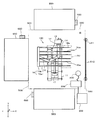
- FIG. 2 is a plan view showing an example of a layout of a production line (robot system) including the robot according to the embodiment of the present invention.
- the robot system includes a robot 100 as an industrial robot, a controller 200, a host device 300, a teaching operation terminal (teaching pendant) 400, a safety fence 500, and a liquid crystal display manufacturing device 550, Various devices and instruments are electrically connected by wire or wireless, or are electrically connected using a serial cable.
- the robot 100 is an industrial robot for transporting a glass substrate 10 for liquid crystal display (hereinafter referred to as “substrate 10”) as a workpiece.
- the robot 100 includes a base 11, a rotation unit 12, a column 13, a slider 14 (a support member that supports the arm 15), and two arms 15.
- the arm 15 includes a hand 16 at the tip thereof.
- the hand 16 has a fork portion 16a and a hand base end portion 16b, and carries the substrate 10 on the fork portion 16a.
- the rotation unit 12 is a base member in which the column 13 is established, and is rotatably arranged on the base 11.
- the rotation unit 12 rotates around the Z axis to turn the robot 100 and change its direction. Can be done.
- the rotating unit 12 can be moved on the base 11 in the Y-axis direction in the figure by a horizontal movement mechanism (not shown).
- the slider 14 is configured to be slidable up and down on the side surface of the column 13 (movable in the Z-axis direction in the figure).
- the two arms 15 move the hand 16 in the direction of taking out and supplying the substrate 10 by a rotational drive source (not shown).
- the arm 15 extends and contracts so that the hand 16 moves in one direction and moves linearly between the extended position where the arm 15 is fully extended and the retracted position where the arm 15 is folded. That is, in this embodiment, it reciprocates in the X direction in the figure.
- the substrate 10 is stored in the manufacturing apparatus 550 located at the extended position, or the substrate 10 is carried out to the contracted position.
- the robot 100 is a transfer robot for transferring the substrate 10, and is particularly a large robot suitable for transferring the large glass substrate 10 as a workpiece.
- the glass substrate 10 has, for example, a substantially square shape with a side of about 3 m and a considerable weight. Therefore, in the case of an emergency stop, there is a possibility of dangerous operations such as dropping of the slider 14 or jumping out of the arm 15, and when an operator enters the work area R, it is very dangerous. It is necessary to brake.
- the robot 100 in FIG. 2 conveys a larger substrate 10 than the robot 100 in FIG. 1, and the number of fork portions 16 a is six according to the size of the substrate 10.
- the rotation unit 12 of the robot 100 of FIG. 2 has a balancer 17 on the opposite side of the rotation diameter from the position where the column 13 is established, and balances the weight during rotation.
- Such a robot 100 is installed in a place (working area R) surrounded by the safety fence 500 and the liquid crystal display manufacturing apparatus 550.
- the controller 200 is electrically connected to the robot 100 by a wire such as a serial cable and is driven to move in the X axis, Y axis, Z axis, and ⁇ axis directions in the figure by a servo motor (not shown). 100 is servo controlled.
- the controller 200 is arranged in the safety fence 500 in FIG. 2, but it may be outside the safety fence, and its layout can be changed as appropriate according to the system requirements.
- the controller 200 is provided with an emergency stop switch 205. The internal configuration of the controller 200 will be described later.
- the host device 300 functions as a central control unit for a line composed of several lanes. More specifically, the host device 300 is configured as an external control panel that controls the entire production line (system) including peripheral devices such as the robot 100 and the manufacturing device 550, and is electrically connected to the controller 200 to be a safety fence. It is arranged outside 500. In addition, the host device 300 is electrically connected to peripheral devices such as the manufacturing device 550, and includes various control switches (not shown) in addition to the emergency stop switch.
- the teaching operation terminal 400 is for teaching the position information to the robot 100, and is connected to the controller 200 by wire such as a serial cable. Then, the teaching operation terminal 400 of the present embodiment includes a mode switch 420 that issues a signal for switching between the automatic operation mode (Remote mode) and the teaching mode (Teach mode) of the robot 100, and teaching in the teaching mode.
- a servo-on switch 421 that issues a signal for enabling the drive current of the servo motor of the robot 100, an emergency stop switch 410 that issues an emergency stop signal corresponding to an emergency stop command, and an enable switch that issues an emergency stop signal according to the switch operation state 430.
- the teaching operation terminal 400 is provided with an LCD display 405 as an output unit at the center of the surface.
- the emergency stop switch 410 is provided on the upper right side of the LCD display 405.
- the mode switch 420 and the servo-on switch 421 are provided in a switch group on the lower right side of the LCD display 405.
- this switch group includes various changeover switches for switching other operation modes.
- a plurality of keys (switches) 415 are provided on the right side of the LCD display 405. These are switches for moving the robot 100 from the current position to a predetermined target position for teaching, and move in the X-axis, Y-axis, Z-axis, and ⁇ -axis directions. Y-axis jog feed operation key, Z-axis jog feed operation key, and the like.
- the enable switch 430 is provided on the rear side of the teaching operation terminal 400, and in the vicinity thereof, a grip portion 435 for the operator to grip the controller 400 is provided (see FIG. 1B).
- the enable switch 430 is a switch for avoiding a danger that is turned on when the operator grasps lightly and is turned off when the worker releases or strongly grasps.
- the enable switch 430 is desirable to be provided integrally with or close to the grip portion 435 so that they can be pressed simultaneously, and may be attached to the rear surface of the grip portion of the teaching operation terminal, which is also called a deadman switch.
- the enable switch 430 is for emergency stop of the robot 100 by turning on / off the servo of the robot controller 200.
- the arrangement of the operation keys, the operation mode changeover switch, and the like described above is merely an example, and may be an arrangement mode / operation mode (for example, a lever switch type) different from that shown in FIG.
- the safety fence 500 is provided to prevent the worker from inadvertently entering the operation range of the robot 100 and to ensure the safety of the worker. More specifically, as shown in FIG. 2, three liquid crystal display manufacturing apparatuses 550 as peripheral devices surround the robot 100 at positions where three of the four sides of the safety fence 500 are opened. Installed. A work area R of the robot 100 is formed by the safety fence 500 and the manufacturing apparatus 550. Instead of the manufacturing apparatus 550, a conveyor apparatus for connecting to another manufacturing line, a connection apparatus for the conveyor apparatus, or a substrate cassette apparatus for stacking and storing a plurality of substrates 10 may be disposed.
- the safety fence 500 is provided with an opening / closing door 510, and an interlock device 511 for detecting the opening / closing state of the opening / closing door 510 is attached. Therefore, when the operator opens the opening / closing door 510 of the safety fence 500 in the automatic operation mode (Remote mode), a system is configured in which the interlock device 511 is activated to cause the robot 100 to perform an emergency stop. Furthermore, an emergency stop device 600 that issues an emergency stop signal for emergency stop of the robot 100 or the peripheral device 550 in the event of a dangerous situation or system failure is provided in various places.
- the emergency stop device 600 includes, for example, an emergency stop button and a duplex switch corresponding to the emergency stop button.
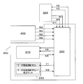
- FIG. 3 is a block diagram showing an electrical configuration of the robot system according to the embodiment of the present invention.
- the controller 200 includes a robot controller control board 210 that processes a control command of the robot 100, a safety PLC 220 that controls emergency stop of the robot body, and a welding detection means 230 that detects welding of a servo power cutoff relay. ing.
- the robot controller control board 210 includes a central control device CPU and storage devices such as ROM and RAM.
- the robot 100 is controlled in accordance with commands relating to linear motion, rotational motion, and each axis motion in various coordinate systems based on the motion program and motion parameters of the robot 100 stored in the storage device.
- the signal input from the teaching operation terminal 400 is for changing and correcting the operation program and operation parameters of the robot 100.
- the safety PLC 220 receives a safety signal from the teaching operation terminal 400 and a safety signal from the host device 300.
- the safety-related signal from the teaching operation terminal 400 is a signal (N2, N4, N5, N8 in the order shown in the figure) issued from the emergency stop switch 410, the enable switch 430, the mode switch 420, and the servo-on switch 421. is there.
- the safety-related signals from the host device 300 are a signal N1 emitted from the emergency stop device, a signal N3 emitted from the interlock device, and a maintenance signal N7.
- Signals not related to safety from the teaching operation terminal 400 are directly input to the robot controller control board 210.
- the monitoring results of the emergency stop device and the enable switch (Y2 and Y3 in the order shown in the figure) are transmitted from the safety PLC 220 to the host device 300, and a safety PLC error signal or the like is sent from the safety PLC 220 to the robot controller control board 210.
- the safety PLC teaching / remote signal Y4 is output.
- a robot system error signal N 6 is output from the robot controller control board 210 to the safety PLC 220. Details thereof will be described with reference to FIG.
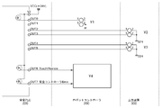
- FIG. 4 is a diagram for explaining an input unit of the safety PLC according to the embodiment of the present invention
- FIG. 5 is a diagram for explaining an output unit of the safety PLC according to the embodiment of the present invention.
- the input unit includes an emergency stop input N1 from the host device 300, an emergency stop input N2 from the teaching operation terminal 400, an interlock signal N3 from the host device 300, and an emergency stop signal N4 issued from the enable switch of the teaching operation terminal 400.
- the servo-on signal N8 and the welding detection signal N9 emitted from the welding detection means 230 are input.
- a detection signal related to welding of the external relay of the emergency stop device 600 of the peripheral device controlled by the host device 300 may be input.
- an output signal Y1 to the servo power cut-off relay From the output unit, an output signal Y1 to the servo power cut-off relay, an output signal to the host device 300 (an emergency stop device monitor signal Y2 and an enable switch monitor signal Y3), an output signal Y4 to the robot controller control board 210
- Each signal (Teach / Remote read signal, safety PLC error signal) is output.
- a safety PLC can generally easily change the operation of internal safety logic, it can achieve high flexibility such as the addition of an interlock circuit function.
- the two hands 16 and the two arms 15 are arranged so as to overlap in the vertical direction. That is, the robot 100 of this embodiment is a double arm type robot.
- the robot 100 may be a single arm type robot including one hand 16 and one arm 15.
- a double arm type robot that conveys a glass substrate as a workpiece is illustrated, but a robot that conveys a semiconductor wafer or the like may be used.
- the present invention is not limited to a robot system for transporting a substrate, but can be applied to other types of robots and other industrial equipment.
- Robot body 100 Robot body 200 Controller 210 Robot controller control board 220 Safety PLC 300 Host device 400 Teaching operation terminal 500 Safety fence
Landscapes
- Engineering & Computer Science (AREA)
- Physics & Mathematics (AREA)
- General Physics & Mathematics (AREA)
- Automation & Control Theory (AREA)
- Robotics (AREA)
- Mechanical Engineering (AREA)
- Manipulator (AREA)
- Numerical Control (AREA)
- Safety Devices In Control Systems (AREA)
Abstract
Description
(3) 前記安全機器は、上位装置に設けられた非常停止機器及び/又は前記ロボット本体を囲う安全柵のドア開放に連動するインターロック装置であることを特徴とするロボットシステム。
図1(a)は、本発明の実施の形態に係るロボット本体のシステムの構成を示す図、図1(b)は(a)の教示操作端末400の側面図である。また、図2は、本発明の実施の形態に係るロボットを含む生産ライン(ロボットシステム)のレイアウトの一例を示す平面図である。
図3は、本発明の実施の形態に係るロボットシステムの電気的構成を示すブロック図である。
本形態では、2個のハンド16と2本のアーム15とが上下方向に重なるように配置されている。すなわち、本形態のロボット100は、ダブルアームタイプのロボットである。なお、ロボット100は、1個のハンド16と1本のアーム15とを備えるシングルアームタイプのロボットであっても良い。さらに、本実施の形態では、ワークとしてガラス基板を搬送するダブルアーム型ロボットを例示したが、半導体ウエハ等を搬送するロボットであっても良い。また、本発明は基板を搬送するロボットのシステムに限定されるものではなく、他の形式用途のロボットやその他の産業機器にも適用することができる。
200 コントローラ
210 ロボットコントローラ制御基板
220 安全PLC
300 上位装置
400 教示操作端末
500 安全柵
Claims (4)
- ロボット本体と、
前記ロボット本体の作動を制御するコントローラと、
前記コントローラに接続され、前記ロボット本体に対する教示を行うための教示データが入力される教示操作端末と、
よりなるロボットシステムにおいて、
前記教示操作端末は、
前記ロボット本体の自動運転モードと教示モードとを切り替える信号を発するモード切替スイッチと、
教示モードにおける教示の際に、前記ロボット本体のサーボモータの駆動電流を有効にする信号を発するサーボオンスイッチと、
非常停止命令に対応する非常停止信号を発する非常停止スイッチと、
スイッチ操作状態に応じて非常停止信号を発するイネーブルスイッチと、を備え、
前記ロボットコントローラは、前記ロボット本体の非常停止を制御する安全PLCを備え、
前記安全PLCには、前記モード切替スイッチ、前記サーボオンスイッチ、前記非常停止スイッチ及び前記イネーブルスイッチからの信号が直接入力されることを特徴とするロボットシステム。 - 前記ロボット本体を非常停止させる非常停止信号を発する安全機器を備え、
前記安全PLCには、前記安全機器からの信号が直接入力されることを特徴とする請求項1記載のロボットシステム。 - 前記安全機器は、上位装置に設けられた非常停止機器及び/又は前記ロボット本体を囲う安全柵のドア開放に連動するインターロック装置であることを特徴とする請求項2記載のロボットシステム。
- 前記安全PLCには、前記サーボモータの駆動電流を遮断するサーボ電源遮断用リレーの溶着を検知するセンサーの溶着検知信号が直接入力されることを特徴とする請求項1から3のいずれか記載のロボットシステム。
Priority Applications (2)
| Application Number | Priority Date | Filing Date | Title |
|---|---|---|---|
| CN201080052963.6A CN102666033B (zh) | 2009-10-21 | 2010-10-20 | 机器人系统 |
| KR1020127009883A KR101704094B1 (ko) | 2009-10-21 | 2010-10-20 | 로봇 시스템 |
Applications Claiming Priority (2)
| Application Number | Priority Date | Filing Date | Title |
|---|---|---|---|
| JP2009-242294 | 2009-10-21 | ||
| JP2009242294A JP5830755B2 (ja) | 2009-10-21 | 2009-10-21 | ロボットシステム |
Publications (1)
| Publication Number | Publication Date |
|---|---|
| WO2011049136A1 true WO2011049136A1 (ja) | 2011-04-28 |
Family
ID=43900359
Family Applications (1)
| Application Number | Title | Priority Date | Filing Date |
|---|---|---|---|
| PCT/JP2010/068506 Ceased WO2011049136A1 (ja) | 2009-10-21 | 2010-10-20 | ロボットシステム |
Country Status (4)
| Country | Link |
|---|---|
| JP (1) | JP5830755B2 (ja) |
| KR (1) | KR101704094B1 (ja) |
| CN (1) | CN102666033B (ja) |
| WO (1) | WO2011049136A1 (ja) |
Cited By (4)
| Publication number | Priority date | Publication date | Assignee | Title |
|---|---|---|---|---|
| JP2014206940A (ja) * | 2013-04-15 | 2014-10-30 | 株式会社安川電機 | 機器制御システム及びコントローラ |
| CN113232018A (zh) * | 2021-04-27 | 2021-08-10 | 成都飞机工业(集团)有限责任公司 | 一种机器人姿态快速复位的方法 |
| CN116352694A (zh) * | 2021-12-28 | 2023-06-30 | 上银科技股份有限公司 | 机电系统的教导设备 |
| US20250096029A1 (en) * | 2017-07-11 | 2025-03-20 | Brooks Automation Us, Llc | Transport apparatus and adapter pendant |
Families Citing this family (17)
| Publication number | Priority date | Publication date | Assignee | Title |
|---|---|---|---|---|
| JP2011165058A (ja) * | 2010-02-12 | 2011-08-25 | Jtekt Corp | 安全制御盤及び安全制御システム |
| JP5970713B2 (ja) * | 2012-11-30 | 2016-08-17 | セイコーエプソン株式会社 | ロボットコントローラー |
| CN103955160A (zh) * | 2014-05-08 | 2014-07-30 | 安徽埃夫特智能装备有限公司 | 一种工业机器人的安全保护模块 |
| CN105437250A (zh) * | 2014-09-01 | 2016-03-30 | 赵德朝 | 一种串联工程机器人 |
| JP6451323B2 (ja) | 2015-01-06 | 2019-01-16 | 株式会社デンソーウェーブ | ロボットの配線方法 |
| DE102015001741A1 (de) * | 2015-02-11 | 2016-08-11 | Kuka Roboter Gmbh | Verfahren und System zum Betreiben einer mehrachsigen Maschine, insbesondere eines Roboters |
| CN106584452B (zh) * | 2015-10-19 | 2019-11-12 | 沈阳新松机器人自动化股份有限公司 | 机器人通用安全控制装置 |
| JP6572092B2 (ja) * | 2015-10-21 | 2019-09-04 | ファナック株式会社 | 視覚センサを用いた動体システム |
| CN108582090B (zh) * | 2017-12-29 | 2021-06-11 | 河北炫烨智能科技股份有限公司 | 高速公路护栏上移动的监控机器人 |
| CN111897244A (zh) * | 2020-06-29 | 2020-11-06 | 埃夫特智能装备股份有限公司 | 一种工业机器人安全控制系统 |
| WO2022044906A1 (ja) * | 2020-08-25 | 2022-03-03 | ファナック株式会社 | ロボット制御装置 |
| WO2022081577A1 (en) * | 2020-10-12 | 2022-04-21 | The Johns Hopkins University | Robot watchdog |
| JP7634357B2 (ja) | 2020-11-09 | 2025-02-21 | ニデックインスツルメンツ株式会社 | 産業用ロボットの制御装置 |
| CN112666858B (zh) * | 2020-12-11 | 2024-02-06 | 珠海格力电器股份有限公司 | 一种机器人的控制装置及机器人 |
| JP7703331B2 (ja) * | 2021-02-02 | 2025-07-07 | ニデックインスツルメンツ株式会社 | 制御装置及び産業用ロボット |
| KR102730986B1 (ko) * | 2022-01-10 | 2024-11-14 | 하이윈 테크놀로지스 코포레이션 | 전자기계 시스템의 티칭 장비 |
| US12112904B2 (en) | 2022-01-25 | 2024-10-08 | Hiwin Technologies Corp. | Teaching pendant of an electromechanical system |
Citations (5)
| Publication number | Priority date | Publication date | Assignee | Title |
|---|---|---|---|---|
| JP2001088068A (ja) * | 1999-09-21 | 2001-04-03 | Denso Corp | ロボットの教示装置 |
| WO2007010795A1 (ja) * | 2005-07-19 | 2007-01-25 | Omron Corporation | 作業者安全管理システム |
| WO2008149618A1 (ja) * | 2007-06-04 | 2008-12-11 | Idec Corporation | 制御装置 |
| JP2009210621A (ja) * | 2008-02-29 | 2009-09-17 | Idec Corp | 安全機器教育用ツール及びその組み立てキット |
| JP2009217848A (ja) * | 2009-06-29 | 2009-09-24 | Nidec Sankyo Corp | モータ駆動制御回路 |
Family Cites Families (5)
| Publication number | Priority date | Publication date | Assignee | Title |
|---|---|---|---|---|
| JPS63318287A (ja) | 1987-06-19 | 1988-12-27 | 三菱電機株式会社 | ロボットの非常停止装置 |
| JPH03136790A (ja) | 1989-10-19 | 1991-06-11 | Tokico Ltd | ロボットシステムの非常停止回路 |
| JPH0811074A (ja) | 1994-06-29 | 1996-01-16 | Fanuc Ltd | ロボットシステム |
| JP2003228418A (ja) | 2002-02-06 | 2003-08-15 | Toshiba Mach Co Ltd | 産業用ロボットの制御装置およびその装置における表示方法 |
| US7272456B2 (en) * | 2003-01-24 | 2007-09-18 | Rockwell Automation Technologies, Inc. | Position based machine control in an industrial automation environment |
-
2009
- 2009-10-21 JP JP2009242294A patent/JP5830755B2/ja active Active
-
2010
- 2010-10-20 KR KR1020127009883A patent/KR101704094B1/ko active Active
- 2010-10-20 CN CN201080052963.6A patent/CN102666033B/zh active Active
- 2010-10-20 WO PCT/JP2010/068506 patent/WO2011049136A1/ja not_active Ceased
Patent Citations (5)
| Publication number | Priority date | Publication date | Assignee | Title |
|---|---|---|---|---|
| JP2001088068A (ja) * | 1999-09-21 | 2001-04-03 | Denso Corp | ロボットの教示装置 |
| WO2007010795A1 (ja) * | 2005-07-19 | 2007-01-25 | Omron Corporation | 作業者安全管理システム |
| WO2008149618A1 (ja) * | 2007-06-04 | 2008-12-11 | Idec Corporation | 制御装置 |
| JP2009210621A (ja) * | 2008-02-29 | 2009-09-17 | Idec Corp | 安全機器教育用ツール及びその組み立てキット |
| JP2009217848A (ja) * | 2009-06-29 | 2009-09-24 | Nidec Sankyo Corp | モータ駆動制御回路 |
Cited By (6)
| Publication number | Priority date | Publication date | Assignee | Title |
|---|---|---|---|---|
| JP2014206940A (ja) * | 2013-04-15 | 2014-10-30 | 株式会社安川電機 | 機器制御システム及びコントローラ |
| US20250096029A1 (en) * | 2017-07-11 | 2025-03-20 | Brooks Automation Us, Llc | Transport apparatus and adapter pendant |
| US12575375B2 (en) * | 2017-07-11 | 2026-03-10 | Brooks Automation Us, Llc | Transport apparatus and adapter pendant |
| CN113232018A (zh) * | 2021-04-27 | 2021-08-10 | 成都飞机工业(集团)有限责任公司 | 一种机器人姿态快速复位的方法 |
| CN113232018B (zh) * | 2021-04-27 | 2022-05-10 | 成都飞机工业(集团)有限责任公司 | 一种机器人姿态快速复位的方法 |
| CN116352694A (zh) * | 2021-12-28 | 2023-06-30 | 上银科技股份有限公司 | 机电系统的教导设备 |
Also Published As
| Publication number | Publication date |
|---|---|
| JP5830755B2 (ja) | 2015-12-09 |
| JP2011088241A (ja) | 2011-05-06 |
| KR20120098629A (ko) | 2012-09-05 |
| KR101704094B1 (ko) | 2017-02-07 |
| CN102666033B (zh) | 2015-05-06 |
| CN102666033A (zh) | 2012-09-12 |
Similar Documents
| Publication | Publication Date | Title |
|---|---|---|
| JP5830755B2 (ja) | ロボットシステム | |
| KR101691777B1 (ko) | 산업용 로봇 | |
| CN103987496B (zh) | Nc机床系统 | |
| KR20090013095A (ko) | 로봇 본체와, 부가 동작 축을 구비한 부가 메커니즘을 갖춘로봇용 제어 장치 | |
| JP5011507B2 (ja) | ロボット教示システム及びロボット教示方法 | |
| KR102564800B1 (ko) | 산업용 로봇의 제어 장치 | |
| JP7205972B2 (ja) | 教示システム | |
| EP1906284A1 (en) | A control device for controlling an industrial robot | |
| US7738998B2 (en) | Robot device | |
| JP7691820B2 (ja) | ロボットシステム及びその制御方法 | |
| KR20140086486A (ko) | 제어기 일체형 포터블 용접로봇 시스템 | |
| JP2010264538A (ja) | ロボット制御装置 | |
| KR200290991Y1 (ko) | 직선운동과 회전운동이 가능한 단일축 로봇 | |
| WO2007107278A2 (en) | Manipulator with control means and a remote main controller communicating via wireless means | |
| Wang | Motion control of industrial robot SV3 based on ACL-Win | |
| JP2005250924A (ja) | 製造設備 |
Legal Events
| Date | Code | Title | Description |
|---|---|---|---|
| WWE | Wipo information: entry into national phase |
Ref document number: 201080052963.6 Country of ref document: CN |
|
| 121 | Ep: the epo has been informed by wipo that ep was designated in this application |
Ref document number: 10824985 Country of ref document: EP Kind code of ref document: A1 |
|
| ENP | Entry into the national phase |
Ref document number: 20127009883 Country of ref document: KR Kind code of ref document: A |
|
| 122 | Ep: pct application non-entry in european phase |
Ref document number: 10824985 Country of ref document: EP Kind code of ref document: A1 |