WO2011048938A1 - 遠赤外線歩行者検知装置 - Google Patents
遠赤外線歩行者検知装置 Download PDFInfo
- Publication number
- WO2011048938A1 WO2011048938A1 PCT/JP2010/067400 JP2010067400W WO2011048938A1 WO 2011048938 A1 WO2011048938 A1 WO 2011048938A1 JP 2010067400 W JP2010067400 W JP 2010067400W WO 2011048938 A1 WO2011048938 A1 WO 2011048938A1
- Authority
- WO
- WIPO (PCT)
- Prior art keywords
- image
- far
- unit
- contour
- pedestrian
- Prior art date
- Legal status (The legal status is an assumption and is not a legal conclusion. Google has not performed a legal analysis and makes no representation as to the accuracy of the status listed.)
- Ceased
Links
Images


Classifications
-
- G—PHYSICS
- G08—SIGNALLING
- G08G—TRAFFIC CONTROL SYSTEMS
- G08G1/00—Traffic control systems for road vehicles
- G08G1/16—Anti-collision systems
- G08G1/166—Anti-collision systems for active traffic, e.g. moving vehicles, pedestrians, bikes
-
- G—PHYSICS
- G06—COMPUTING OR CALCULATING; COUNTING
- G06V—IMAGE OR VIDEO RECOGNITION OR UNDERSTANDING
- G06V10/00—Arrangements for image or video recognition or understanding
- G06V10/40—Extraction of image or video features
- G06V10/48—Extraction of image or video features by mapping characteristic values of the pattern into a parameter space, e.g. Hough transformation
-
- G—PHYSICS
- G06—COMPUTING OR CALCULATING; COUNTING
- G06V—IMAGE OR VIDEO RECOGNITION OR UNDERSTANDING
- G06V20/00—Scenes; Scene-specific elements
- G06V20/50—Context or environment of the image
- G06V20/56—Context or environment of the image exterior to a vehicle by using sensors mounted on the vehicle
- G06V20/58—Recognition of moving objects or obstacles, e.g. vehicles or pedestrians; Recognition of traffic objects, e.g. traffic signs, traffic lights or roads
-
- G—PHYSICS
- G06—COMPUTING OR CALCULATING; COUNTING
- G06V—IMAGE OR VIDEO RECOGNITION OR UNDERSTANDING
- G06V40/00—Recognition of biometric, human-related or animal-related patterns in image or video data
- G06V40/10—Human or animal bodies, e.g. vehicle occupants or pedestrians; Body parts, e.g. hands
Definitions
- the present invention relates to a far-infrared pedestrian detection device, and more particularly, to a technique for improving the efficiency of image processing for detecting the location of a pedestrian from a captured image.
- this system installs a far-infrared camera that captures the direction of travel in the vehicle, detects a pedestrian from the captured image, and overlays a marker on the pedestrian part of the image and presents it to the driver. To do. Also, in the future, when a pedestrian is detected by this system, the degree of danger is automatically judged, and if it is judged dangerous, a warning will be given, or a collision will be detected by braking or steering by the automatic control device of the vehicle. It can also be avoided.
- template matching As a method for detecting a pedestrian from an image, so-called template matching is used in which a pedestrian template is prepared in advance and the similarity between this template and an area where a pedestrian may exist in the image is obtained. It is done.
- the method of calculating the similarity is roughly divided into “pixel value comparison” and “contour information comparison” methods.
- the contour information does not depend on the brightness of the image, so it is suitable for outdoor use such as for vehicles where the brightness of the image varies greatly depending on the weather and the sun position. Furthermore, since the contour information can be expressed with binary or a small number of gradations, the amount of data to be handled is small, and the amount of calculation of similarity in template matching that occupies a large amount of processing in the pedestrian detection processing can be small.
- processing for increasing the contrast of the entire screen is performed to clarify the difference between values stored in the respective pixels of the captured image (hereinafter referred to as pixel values), thereby enhancing the contour of the image.
- the image in which the contour is emphasized is subjected to matching processing with a template prepared in advance, in which the contour of the pedestrian is emphasized, and a correlation value between each part of the image and the template (template in the image). (Correlation map expressed by correlation value for each position).
- an area where a pedestrian an image of the pedestrian
- the cut-out image is enlarged or reduced so as to be the same size as the template.
- the region represented by the large correlation value in the correlation map is Although the area has a certain size, the part where the template is applied to the position showing the maximum correlation value in the area is a candidate part where a pedestrian image exists.
- template matching processing for detecting pedestrians is performed on the entire captured image.
- the template matching process needs to calculate the correlation between the captured image and the template for each pixel in the captured image while shifting the position of the template. Even when using, there is a problem that a large computer load is applied.
- the present invention has been made in view of the above circumstances, and an object thereof is to provide a far-infrared pedestrian detection device capable of reducing the computer load of pedestrian detection processing.
- the far-infrared pedestrian detection device detects the position of the infinity point from the captured image, sets the detection area of the pedestrian based on the position of the infinity point, and then detects the pedestrian. By performing pedestrian detection only on the area, the load of computer processing is reduced.
- the far-infrared pedestrian detection device is the far-infrared pedestrian detection device that detects the position of a pedestrian from an image captured by a far-infrared imaging unit having sensitivity to far-infrared rays.
- An infinite point detection unit that obtains the position of an infinite point in the image based on the obtained image, and a detection area for detecting the position of a pedestrian according to the position of the infinite point are set.
- a pedestrian detection area setting unit is set.
- the infinity point detection unit detects the position of the infinity point from the image captured by the imaging unit, and the pedestrian detection region
- a template matching process is performed as computer processing means for detecting a pedestrian in order that the setting unit limits the detection area of the pedestrian in the captured image according to the position of the detected infinity point. What is performed can reduce the computer load required for the template matching process.
- the infinite point detection unit includes a contour constituent point in which a difference in pixel value between adjacent pixels in the image is a predetermined value or more, and the A contour detection unit that detects a direction in which a contour extends at a contour component point, a contour component point in which a direction in which the contour extends is horizontal or nearly horizontal among the contour component points detected by the contour detector, and the contour A specific contour component removing unit that removes contour constituent points that are perpendicular or nearly perpendicular to each other, a position of the contour constituent point that is not removed by the specific contour component removing unit, and a direction in which the contour extends at the contour constituent point
- the straight line detection unit that detects two straight lines whose extending directions are separated by a predetermined value or more, and specifies the position of the infinity point based on the two detected straight lines. It is desirable that the formation.
- the position of the infinity point in the image among the contour constituent points detected by the contour detection unit by the specific contour component removal unit is determined. Since the contour composing point where the extending direction of the contour is horizontal or nearly horizontal, and the contour composing point that is vertical or nearly vertical, which may not be used as information for specifying, are removed in advance, the position of the infinity point is determined. It can be detected accurately.
- the far-infrared pedestrian detection device from the Hough space that is generated by the specific contour component removal unit by performing a Hough transform on the contour component point detected by the contour detection unit,
- the information corresponding to a horizontal line that passes through the contour constituent point, or a straight line that is close to horizontal, and a vertical line that is close to vertical, or a line that is close to vertical, is removed. Based on this, it is desirable that the straight line be detected.
- the parameter space (Hough transform) generated by the Hough transform is applied.
- the horizontal or near-horizontal contour component, or the vertical or near-vertical contour component is all removed, and further, the specified contour component is removed, and the Hough space is separated by a predetermined angle or more.
- the straight line detection can be performed by detecting the maximum values corresponding to the two straight lines, the two straight lines necessary for determining the position of the infinity point can be detected by a simple procedure.
- the far-infrared pedestrian detection device detects an image portion of the image represented in the template by performing comparison and collation with a predetermined template for the identified pedestrian detection area.
- a template matching unit, a marker superimposing unit that superimposes and outputs a predetermined marker on an image portion detected by the template matching unit, and an image display unit that displays predetermined information are mounted on the vehicle and obtained by imaging.
- the image is an image obtained by capturing a predetermined area in the traveling direction of the vehicle, and the template matching unit is configured to collate with a template to which a pedestrian image is applied as the template image. desirable.
- the template matching unit displays the pedestrian image. Therefore, it is not necessary to perform template matching on the entire captured image. Therefore, the predetermined marker can be accurately superimposed on the pedestrian image portion of the captured far-infrared image, and the occupant such as the driver can be alerted to the pedestrian.
- an effect of reducing the computer load of image processing performed for pedestrian detection can be obtained.
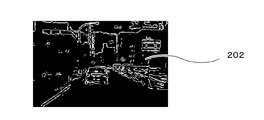
- FIG. It is a figure which shows the outline constituent point image 202 which extracted the point which comprises an outline from the outline emphasis image 201.
- FIG. It is a figure explaining (theta) and (rho) calculated in Hough transformation.
- FIG. It is a figure which shows the specific outline component removal image 204 which removed the outline component from which the outline extending direction is horizontal or near vertical from the Hough conversion image 203.
- FIG. 2 is a diagram showing a positional relationship among a pedestrian K3, a lens K1 that constitutes the far-infrared imaging unit 10, and an imaging element K2 that constitutes the far-infrared imaging unit 10.
- FIG. It is a figure which shows the pedestrian detection area
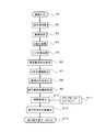
- FIG. 1 is a block diagram showing a schematic configuration of a far-infrared pedestrian detection device 100 according to an embodiment of the present invention
- FIG. 2 shows a detailed configuration of a pedestrian detection unit 20 in the far-infrared pedestrian detection device 100 of FIG.
- FIG. 3 shows a pedestrian image detection process by the infinity point detection unit 30, the pedestrian detection region setting unit 40, and the template matching unit 50 in the pedestrian detection unit 20 shown in FIG. It is a flowchart.
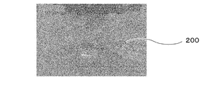
- a far-infrared pedestrian detection device 100 is a far-infrared imaging unit 10 that is installed in a vehicle and images a predetermined area in the traveling direction as a far-infrared image 200 (see FIG. 4). Based on the far-infrared image 200 captured by the far-infrared imaging unit 10, an image representing a pedestrian is detected from the far-infrared image 200, and a rectangular frame (marker) is superimposed on the detected pedestrian image.
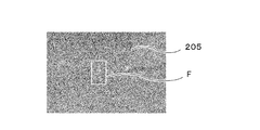
- the pedestrian detection unit 20 that outputs the image and the image display unit 70 that displays the far-infrared image 205 with the rectangular frame F (see FIG. 16) attached to the position of the pedestrian image.
- the far-infrared imaging unit 10 includes therein an optical system (lens K1) and an imaging element K2 for converting an image of the outside world into an electrical signal.
- the pedestrian detection unit 20 includes an infinity point detection unit 30, a pedestrian detection region setting unit 40, a template matching unit 50, and a marker superimposing unit 60, as shown in FIG.
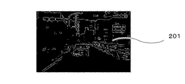
- the infinity point detection unit 30 emphasizes the contour of the image with respect to the pixel value adjustment unit 31 that increases the contrast of the far-infrared image 200 and the image whose contrast is increased by the pixel value adjustment unit 31.
- a contour detection unit that generates an image 201 (see FIG. 5), further extracts pixels having a contour strength equal to or greater than a predetermined value as contour constituent points, and generates a contour constituent point image 202 (see FIG. 6).
- a specific contour component removal unit 34 that removes a contour component in a specific direction from the converted image 203, and a specific contour component removal image 2 in which the contour component in the specific direction is removed by the specific contour component removal unit 34.
- a straight line detection unit 35 for detecting two straight lines having a direction more than a predetermined value, and a straight line intersection for obtaining an intersection of the two straight lines detected by the straight line detection unit 35 It is the structure provided with the calculation part 36.
- the Hough transform performed by the Hough transform unit 33 is widely used as an image processing technique for detecting a linear component from a given image. More specifically, first, an arbitrary straight line passing through the contour constituting point (x, y) in the image is assumed. At this time, assuming that the perpendicular length down from the origin of the image to the straight line is ⁇ and the angle between ⁇ and the horizontal axis of the image is ⁇ , the relationship of (Equation 1) is established between ⁇ and ⁇ .
- the pedestrian detection area setting unit 40 sets an area where a pedestrian is assumed to exist based on the position of the infinity point in the far-infrared image 200 detected by the infinity point detection unit 30. is there.
- the template matching unit 50 performs a template matching process between the contour-enhanced image 201 and the pedestrian template stored in the template storage unit 52 for the region set by the pedestrian detection region setting unit 40. And a correlation value calculation unit 51 that obtains a correlation value between the contour-enhanced image 201 and the pedestrian template, and a walking that detects a pedestrian's location based on the correlation value calculated by the correlation value calculation unit 51
- the person presence position detection unit 53 is provided.
- the marker superimposing unit 60 superimposes the rectangular frame F shown in FIG. 16 on the position of the pedestrian image obtained by the template matching unit 50 in the far infrared image 200 obtained by the far infrared imaging unit 10. Output.
- the far-infrared imaging unit 10 installed in the vehicle images a predetermined region in the traveling direction of the vehicle, and for example, a far-infrared image such as a far-infrared image 200 shown in FIG. 4 or a far-infrared image 205 shown in FIG. Is imaged.
- a far-infrared image such as a far-infrared image 200 shown in FIG. 4 or a far-infrared image 205 shown in FIG. Is imaged.
- a large value is stored in a target portion that emits heat, such as a human body, as in a far-infrared image 205 shown in FIG. 16, for example, and brightly observed on the image.
- the far-infrared image 200 captured by the far-infrared imaging unit 10 is input to the pixel value adjusting unit 31 in step 1 (S1) of FIG.
- the pixel value adjusting unit 31 performs a process for increasing the contrast of the input far-infrared image 200 in order to more effectively enhance the contour to be performed later (S2 in FIG. 3).
- the maximum value and the minimum value of the pixel value in the far-infrared image 200 are obtained, and if the pixel value is quantized to 8 bits, the maximum value is 255 and the minimum value. Is converted to 0, the intermediate value is linearly interpolated, and a histogram of pixel values is obtained. Pixels having a pixel value smaller than the median value between the median values are between 0 and the median value. For a pixel having a pixel value larger than the median value, a process of converting the pixel value nonlinearly is performed between the median value and 255.
- the method is not limited to the specific method described above, and a process having the same effect as described above may be performed.
- the image whose contrast has been increased by the pixel value adjustment unit 31 is input to the contour detection unit 32.
- the contour detection unit 32 performs differentiation processing on the input image with increased contrast (S3 in FIG. 3). By the differentiation process, a contour-enhanced image 201 (FIG. 5) in which the pixel value of the image changes abruptly and the contour of the object is enhanced is obtained.
- the image differentiation process can be performed by performing a filtering process called spatial filtering using various proposed operators such as the Sobel operator and the Prewitt operator. Since this process is a technique generally used in digital image processing, detailed description thereof is omitted. Here, processing may be performed using any of these operators.
- the contour detection unit 32 extracts contour composing points having a strong contour strength that have a large difference in pixel values between adjacent pixels from the contour-enhanced image 201.
- a binarization process is performed in which “1” is stored in a pixel having a pixel value greater than or equal to a predetermined value in the outline-enhanced image 201 and “0” is stored in other pixels (S4 in FIG. 3).
- the contour composing point image 202 (FIG. 6) is obtained by the binarization process.
- “1” representing the contour composing point is stored in the white pixel
- “0” representing other than the contour composing point is stored in the black pixel.
- the contour composing point image 202 is input to the Hough transform unit 33.
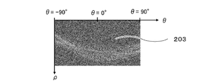
- the Hough transform unit 33 performs Hough transform on the contour component point image 202 (S5 in FIG. 3) to obtain a Hough transform image 203 (FIG. 8).
- FIG. 7 shows a point C (x0, y0) as a representative contour point from the origin O (0, 0), and a straight line L1 as a representative of all straight lines passing through the point C.
- ⁇ corresponding to ⁇ is calculated each time to obtain a combination of ( ⁇ , ⁇ ), and ( ⁇ , ⁇ ) is obtained.
- a Hough transform image 203 called a Hough space is created by incrementing the pixel value of the corresponding coordinate by one.
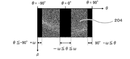
- the generated Hough transform image 203 is input to the specific contour component removal unit 34, and a process of removing the contour extending in the horizontal direction and the vertical direction is performed (S6 in FIG. 3).
- the captured image when detecting an infinite point from an image captured in front of the traveling direction of the vehicle, the captured image generally undergoes perspective transformation, so that the infinite point generally converges toward that point. It is determined as the intersection of multiple straight lines.
- contours that do not provide information for specifying the position of an infinite point, such as contours of obstacles on the road and contours of buildings outside the road.
- the contour extending in the horizontal direction (horizontal contour) and the contour extending in the vertical direction (vertical contour) in the image subjected to the perspective transformation are often unnecessary for specifying the position of the point at infinity.
- the specific contour component removing unit 34 performs a process of removing such a horizontal contour and a vertical contour prior to detection of a point at infinity.
- the following conversion process is performed on the Hough transform image 203 using a preset threshold value ⁇ .
- the Hough transform image 203 is M ( ⁇ , ⁇ )
- the image obtained as a result of the process of removing the specific contour component is N ( ⁇ , ⁇ ) (hereinafter referred to as a specific contour component removed image 204). .
- An example of the specific contour component removal image 204 generated in this way is shown in FIG.
- the processing shown in (Equation 2) and (Equation 3) is specifically a simple process of replacing all pixel values in the range shown in (Equation 2) with 0 for the Hough transform image 203. Can be realized.
- the straight line detector 35 detects two straight lines from the specific contour component removal image 204 (S7 in FIG. 3). This straight line detection process is performed by obtaining two local maximum points that are a predetermined value or more away from the specific contour component removal image 204.
- the ( ⁇ 1, ⁇ 1) and ( ⁇ 2, ⁇ 2) specified in this way represent the upper two straight lines having a large number of contour constituent points in the far-infrared image 200.
- the threshold value ⁇ is provided because the infinity point can be detected with higher accuracy by using two straight lines having different directions as much as possible.
- An example of detection results of ( ⁇ 1, ⁇ 1) and ( ⁇ 2, ⁇ 2) is shown in FIG.
- intersection of the two straight lines ( ⁇ 1, ⁇ 1) and ( ⁇ 2, ⁇ 2) is calculated by the straight line intersection calculation unit 36 (S8 in FIG. 3). Specifically, two straight line expressions specified by ( ⁇ 1, ⁇ 1) and ( ⁇ 2, ⁇ 2) are obtained, and the intersection point is specified by solving the two straight line expressions as simultaneous equations. The intersection calculated in this way represents the position of the infinity point in the far-infrared image 200.
- an area where a pedestrian can be assumed is set based on the calculated position of the infinity point (S9 in FIG. 3).
- the method for setting the pedestrian detection area will be described using specific numerical values.
- the number of pixels of the imaging device of the far-infrared imaging unit 10 is 360 pixels in the horizontal direction and 240 pixels in the vertical direction
- the size of one pixel of the imaging device is 42 ⁇ m (the same size in both the vertical and horizontal directions)
- the range for detecting the pedestrian may be set based on the design requirements of the pedestrian detection system, but here, the distance to the pedestrian L is in the range of 30 m to 90 m, and each of the left and right W is in the range of 5 m. It shall detect pedestrians.
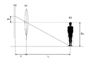
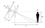
- the vertical position dv of the pedestrian's feet projected on the image sensor is the distance L to the pedestrian, the focal length f of the lens constituting the far-infrared imaging unit 10, and the pedestrian in the layout illustrated in FIG. It is calculated
- K1 represents a lens constituting the far infrared imaging unit 10
- K2 represents an imaging element constituting the far infrared imaging unit 10
- K3 represents a pedestrian.
- the lateral position dh on which the pedestrian's feet are projected onto the image sensor of the far-infrared imaging unit 10 is the distance L to the pedestrian and the far-infrared imaging. From the focal length f of the lens constituting the unit 10 and the horizontal distance Dh from the optical axis of the optical system of the far-infrared imaging unit 10 to the pedestrian, it is obtained by (Equation 5).
- dh Dh ⁇ f / [(Dh 2 + L 2 ) 1/2 ⁇ cos ⁇ tan ⁇ 1 (Dv / L) ⁇ ] (Formula 5)
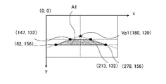
- the amount of leftward deviation from the center of the screen at the foot of the pedestrian is 99 pixels.
- the position of the infinity point in the far infrared image 200 is Vp1 (180, 120).
- the relationship between the installation direction of the far-infrared imaging unit 10 and the traveling road surface changes due to two factors.
- One is due to the mounting error of the camera itself, and the other is due to the vertical movement of the running vehicle.
- the depression angle of the optical axis of the optical system of the far-infrared imaging unit 10 is not 0 ° but 5 ° downward due to an attachment error of the far-infrared imaging unit 10 or a vertical movement of the traveling vehicle.
- the pedestrian detection area where the pedestrian's feet are considered to be present is calculated as follows.
- FIG. 13 shows an imaging model in which the optical axis of the optical system of the far-infrared imaging unit 10 faces the vehicle traveling direction and is inclined ⁇ from the horizontal to the downward direction.
- the center of rotation coincides with the center of the lens, and the optical axis of the optical system is inclined only in the vertical direction.
- K1 represents a lens constituting the far infrared imaging unit
- K2 represents an imaging element constituting the far infrared imaging unit
- K3 represents a pedestrian.
- dv is the vertical position of the pedestrian's feet projected on the image sensor.
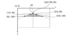
- the position of the infinity point in the far-infrared image 200 is Vp2 (180, 68).
- dv is obtained from (Equation 6) from the distance L to the pedestrian, the focal length f of the lens constituting the far-infrared imaging unit 10, and the height Dv of the pedestrian.
- the lateral position dh of the pedestrian's foot projected on the image sensor is the distance L to the pedestrian, the focal length f of the lens constituting the far-infrared imaging unit 10, and the far-infrared ray. It is calculated by (Equation 7) from the horizontal distance Dh from the optical axis of the optical system of the imaging unit 10 to the feet of the pedestrian.
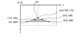
- the position of the infinity point is Vp3 (180, 172)
- the vehicle traveling direction 30 m forward to 90 m forward is the area A3 shown in FIG.
- the position of the pedestrian detection area where the pedestrian's feet are thought to exist corresponds to the position of the infinity point in the far-infrared image 200 on a one-to-one basis. If the position can be specified, the pedestrian detection area can be specified.
- the optical axis of the optical system of the far-infrared imaging unit 10 varies not only in the depression direction but also in the horizontal direction. Also in this case, the pedestrian detection area can be estimated in the same manner as described above.
- the pedestrian detection area setting unit 40 stores in advance position information of the pedestrian detection area that is estimated based on the position of the infinity point in the captured far-infrared image 200, and detects the infinity point. Based on the position coordinates of the infinity point detected by the unit 30, the position information of the pedestrian detection area corresponding to the detected position coordinates of the infinity point is read.
- the template matching unit 50 performs template matching for each pixel inside the pedestrian detection area set in the above-described procedure, and specifies the presence / absence of the pedestrian and the location of the pedestrian.
- an image in which the contour is detected from a far-infrared image obtained by imaging a pedestrian is used as a template.
- the template is stored in the template storage unit 52 in advance.
- the template matching process is performed by applying the template stored in the template storage unit 52 to each pixel in the pedestrian detection area and calculating the correlation value by the correlation value calculation unit 51 each time (in FIG. 3). S10, S11).
- There are various methods for obtaining the correlation value For example, a normalized cross-correlation value is obtained between each pixel in the template and a corresponding pixel of the contour-enhanced image 201 to which the template is applied. What is necessary is just to obtain
- the maximum correlation value is calculated when the template is applied to a position where a pedestrian is present.
- the minimum correlation value is calculated when the template is applied to a position where a pedestrian is present.
- the result calculated by the correlation value calculation unit 51 is compared with a predetermined threshold value to determine whether or not there is a pixel that is larger than or smaller than the threshold value.
- the normalized cross-correlation value it may be determined whether there is a value larger than the threshold value. When a pixel having a correlation value larger than the threshold is found, it is determined that a pedestrian exists at that position, and when a pixel having a correlation value larger than the threshold is not found, it is determined that there is no pedestrian.
- the threshold value and the determination criterion may be set according to the correlation value to be used.
- the position of the pedestrian detected by the correlation value calculation unit 51 is sent to the marker superimposing unit 60, and the marker superimposing unit 60 surrounds the area of the pedestrian image to the minimum based on the position of the pedestrian image.
- a rectangular frame F is set, and this rectangular frame F is superimposed on the position of the pedestrian in the far-infrared image 200 input from the far-infrared imaging unit 10 and output to the image display unit 70.
- the image display unit 70 displays an image with a rectangular frame F attached to the pedestrian image of the far-infrared image 200 sent from the marker superimposing unit 60 (S13 in FIG. 3).
- FIG. 16 shows an example of the far-infrared image 205 generated in this way.
- ⁇ 90 °
- ⁇ 90 °
- ⁇ may be set to a value not exceeding 140 °.
- the position of an infinite point in the image captured by the far-infrared imaging unit 10 having sensitivity to far infrared is obtained at infinity.
- the pedestrian detection area in the captured image is limited by including a point detection section and a pedestrian detection area setting section for detecting the position of the pedestrian according to the position of the infinity point. be able to.
- the pedestrian detection area is limited to a predetermined range, but the far-infrared pedestrian detection device according to the present invention is limited to this form.
- a pedestrian according to the travel speed of the vehicle acquired by a sensor provided in the vehicle or according to the width of the road currently being traveled acquired by a navigation system provided in the vehicle.
- a configuration in which the position and size of the detection area are changed can also be adopted.
- the configuration described above is also implemented by dynamically changing the size of the pedestrian detection area and specifying the position of the pedestrian detection area based on the position of the infinity point in the far-infrared image. The same action and effect as the form can be exhibited.
- This application claims priority based on Japanese Patent Application No. 2009-244443 filed with the Japan Patent Office on October 23, 2009, the entire disclosure of which is fully incorporated herein by reference.
Landscapes
- Engineering & Computer Science (AREA)
- Physics & Mathematics (AREA)
- General Physics & Mathematics (AREA)
- Multimedia (AREA)
- Theoretical Computer Science (AREA)
- Human Computer Interaction (AREA)
- Traffic Control Systems (AREA)
- Image Processing (AREA)
- Closed-Circuit Television Systems (AREA)
- Image Analysis (AREA)
Priority Applications (3)
| Application Number | Priority Date | Filing Date | Title |
|---|---|---|---|
| US13/503,466 US20120212615A1 (en) | 2009-10-23 | 2010-10-05 | Far-infrared pedestrian detection device |
| CN2010800478649A CN102598056A (zh) | 2009-10-23 | 2010-10-05 | 远红外线行人探测装置 |
| EP10824787.5A EP2492868A4 (en) | 2009-10-23 | 2010-10-05 | DEVICE FOR DETECTION OF FAR INFRARED PEDESTRIAN |
Applications Claiming Priority (2)
| Application Number | Priority Date | Filing Date | Title |
|---|---|---|---|
| JP2009-244443 | 2009-10-23 | ||
| JP2009244443A JP5401257B2 (ja) | 2009-10-23 | 2009-10-23 | 遠赤外線歩行者検知装置 |
Publications (1)
| Publication Number | Publication Date |
|---|---|
| WO2011048938A1 true WO2011048938A1 (ja) | 2011-04-28 |
Family
ID=43900170
Family Applications (1)
| Application Number | Title | Priority Date | Filing Date |
|---|---|---|---|
| PCT/JP2010/067400 Ceased WO2011048938A1 (ja) | 2009-10-23 | 2010-10-05 | 遠赤外線歩行者検知装置 |
Country Status (5)
| Country | Link |
|---|---|
| US (1) | US20120212615A1 (enExample) |
| EP (1) | EP2492868A4 (enExample) |
| JP (1) | JP5401257B2 (enExample) |
| CN (1) | CN102598056A (enExample) |
| WO (1) | WO2011048938A1 (enExample) |
Families Citing this family (10)
| Publication number | Priority date | Publication date | Assignee | Title |
|---|---|---|---|---|
| KR20140019501A (ko) * | 2012-08-06 | 2014-02-17 | 현대자동차주식회사 | 장애물 인식을 위한 분류기의 생성방법 |
| JP6169366B2 (ja) * | 2013-02-08 | 2017-07-26 | 株式会社メガチップス | 物体検出装置、プログラムおよび集積回路 |
| US9336436B1 (en) * | 2013-09-30 | 2016-05-10 | Google Inc. | Methods and systems for pedestrian avoidance |
| JP6230498B2 (ja) * | 2014-06-30 | 2017-11-15 | 本田技研工業株式会社 | 対象物認識装置 |
| US20160161339A1 (en) * | 2014-12-05 | 2016-06-09 | Intel Corporation | Human motion detection |
| CN108229314B (zh) * | 2017-11-28 | 2021-05-04 | 深圳市商汤科技有限公司 | 目标人物的搜索方法、装置和电子设备 |
| CN108171243B (zh) * | 2017-12-18 | 2021-07-30 | 广州七乐康药业连锁有限公司 | 一种基于深度神经网络的医疗图像信息识别方法及系统 |
| US20200342623A1 (en) * | 2019-04-23 | 2020-10-29 | Apple Inc. | Systems and methods for resolving hidden features in a field of view |
| KR20220082968A (ko) * | 2020-12-10 | 2022-06-20 | 현대자동차주식회사 | 차량 운전자의 시야 보조 방법 및 그 보조 장치 |
| CN116129157B (zh) * | 2023-04-13 | 2023-06-16 | 深圳市夜行人科技有限公司 | 一种基于极微光的警戒摄像机智能图像处理方法及系统 |
Citations (3)
| Publication number | Priority date | Publication date | Assignee | Title |
|---|---|---|---|---|
| JP2005316607A (ja) * | 2004-04-27 | 2005-11-10 | Toyota Motor Corp | 画像処理装置及び画像処理方法 |
| JP2006314061A (ja) * | 2005-05-09 | 2006-11-16 | Nissan Motor Co Ltd | 画像処理装置及びノイズ判定方法 |
| JP2008065463A (ja) * | 2006-09-05 | 2008-03-21 | Toyota Motor Corp | 画像処理装置 |
Family Cites Families (7)
| Publication number | Priority date | Publication date | Assignee | Title |
|---|---|---|---|---|
| US5638116A (en) * | 1993-09-08 | 1997-06-10 | Sumitomo Electric Industries, Ltd. | Object recognition apparatus and method |
| JP4650079B2 (ja) * | 2004-11-30 | 2011-03-16 | 日産自動車株式会社 | 物体検出装置、および方法 |
| JP4692081B2 (ja) * | 2005-06-01 | 2011-06-01 | 日産自動車株式会社 | 車載物体検出装置、および物体検出方法 |
| JP4166253B2 (ja) * | 2006-07-10 | 2008-10-15 | トヨタ自動車株式会社 | 物体検出装置、物体検出方法、および物体検出用プログラム |
| WO2008007471A1 (fr) * | 2006-07-10 | 2008-01-17 | Kyoto University | Procédé de suivi d'un marcheur et dispositif de suivi d'un marcheur |
| WO2008139530A1 (ja) * | 2007-04-27 | 2008-11-20 | Honda Motor Co., Ltd. | 車両周辺監視装置、車両周辺監視用プログラム、車両周辺監視方法 |
| US8154633B2 (en) * | 2007-11-16 | 2012-04-10 | Sportvision, Inc. | Line removal and object detection in an image |
-
2009
- 2009-10-23 JP JP2009244443A patent/JP5401257B2/ja not_active Expired - Fee Related
-
2010
- 2010-10-05 EP EP10824787.5A patent/EP2492868A4/en not_active Withdrawn
- 2010-10-05 WO PCT/JP2010/067400 patent/WO2011048938A1/ja not_active Ceased
- 2010-10-05 CN CN2010800478649A patent/CN102598056A/zh active Pending
- 2010-10-05 US US13/503,466 patent/US20120212615A1/en not_active Abandoned
Patent Citations (3)
| Publication number | Priority date | Publication date | Assignee | Title |
|---|---|---|---|---|
| JP2005316607A (ja) * | 2004-04-27 | 2005-11-10 | Toyota Motor Corp | 画像処理装置及び画像処理方法 |
| JP2006314061A (ja) * | 2005-05-09 | 2006-11-16 | Nissan Motor Co Ltd | 画像処理装置及びノイズ判定方法 |
| JP2008065463A (ja) * | 2006-09-05 | 2008-03-21 | Toyota Motor Corp | 画像処理装置 |
Non-Patent Citations (1)
| Title |
|---|
| See also references of EP2492868A4 * |
Also Published As
| Publication number | Publication date |
|---|---|
| JP5401257B2 (ja) | 2014-01-29 |
| EP2492868A1 (en) | 2012-08-29 |
| US20120212615A1 (en) | 2012-08-23 |
| CN102598056A (zh) | 2012-07-18 |
| EP2492868A4 (en) | 2015-01-14 |
| JP2011090556A (ja) | 2011-05-06 |
Similar Documents
| Publication | Publication Date | Title |
|---|---|---|
| JP5401257B2 (ja) | 遠赤外線歩行者検知装置 | |
| KR101517181B1 (ko) | 차선 이탈 경보 시스템 및 방법 | |
| CN104509090B (zh) | 车载用图像识别装置 | |
| KR101605514B1 (ko) | 차선 인식 장치 및 방법 | |
| JP6246014B2 (ja) | 外界認識システム、車両、及びカメラの汚れ検出方法 | |
| JP5399027B2 (ja) | 自動車の運転を支援するための、立体画像を捕捉することができるシステムを有するデバイス | |
| JP6467798B2 (ja) | 画像処理装置、立体物検出方法、立体物検出プログラム、および、移動体制御システム | |
| US20120288154A1 (en) | Road-Shoulder Detecting Device and Vehicle Using Road-Shoulder Detecting Device | |
| EP3545464B1 (en) | Information processing device, imaging device, equipment control system, mobile object, information processing method, and computer-readable recording medium | |
| WO2016002163A1 (ja) | 画像表示装置、画像表示方法 | |
| JP2013061919A (ja) | 外界認識方法,装置,および車両システム | |
| KR101264282B1 (ko) | 관심영역 설정을 이용한 도로상 차량의 검출방법 | |
| WO2016125377A1 (ja) | 画像処理装置、および車両システム | |
| WO2010047226A1 (ja) | 車線区画線検出装置、車線区画線検出方法、及び車線区画線検出プログラム | |
| WO2016129301A1 (ja) | 車両用進入可否判定装置 | |
| KR101268282B1 (ko) | 차량용 내비게이션의 차선 이탈 알림 시스템 및 방법 | |
| JP2012252501A (ja) | 走行路認識装置及び走行路認識用プログラム | |
| JP5083164B2 (ja) | 画像処理装置及び画像処理方法 | |
| KR20180081966A (ko) | 차량 인식을 통한 영상 교정 방법 | |
| CN101978392A (zh) | 车辆用图像处理装置和图像处理程序 | |
| WO2016087317A1 (en) | Driver assistance system, motor vehicle and method for classifying a flow vector | |
| KR20150042417A (ko) | 촬영부를 이용한 차선검출방법 및 차선검출시스템 | |
| JP7229032B2 (ja) | 車外物体検出装置 | |
| JP4432730B2 (ja) | 車両用道路標示検出装置 | |
| JP2022014673A (ja) | 画像処理装置 |
Legal Events
| Date | Code | Title | Description |
|---|---|---|---|
| WWE | Wipo information: entry into national phase |
Ref document number: 201080047864.9 Country of ref document: CN |
|
| 121 | Ep: the epo has been informed by wipo that ep was designated in this application |
Ref document number: 10824787 Country of ref document: EP Kind code of ref document: A1 |
|
| WWE | Wipo information: entry into national phase |
Ref document number: 13503466 Country of ref document: US |
|
| REEP | Request for entry into the european phase |
Ref document number: 2010824787 Country of ref document: EP |
|
| WWE | Wipo information: entry into national phase |
Ref document number: 2010824787 Country of ref document: EP |