WO2011048914A1 - 携帯無線端末、無線端末、無線通信システムおよび無線通信方法 - Google Patents
携帯無線端末、無線端末、無線通信システムおよび無線通信方法 Download PDFInfo
- Publication number
- WO2011048914A1 WO2011048914A1 PCT/JP2010/066786 JP2010066786W WO2011048914A1 WO 2011048914 A1 WO2011048914 A1 WO 2011048914A1 JP 2010066786 W JP2010066786 W JP 2010066786W WO 2011048914 A1 WO2011048914 A1 WO 2011048914A1
- Authority
- WO
- WIPO (PCT)
- Prior art keywords
- channel
- wireless terminal
- unit
- trigger
- wireless communication
- Prior art date
Links
Images

Classifications
-
- A—HUMAN NECESSITIES
- A61—MEDICAL OR VETERINARY SCIENCE; HYGIENE
- A61B—DIAGNOSIS; SURGERY; IDENTIFICATION
- A61B1/00—Instruments for performing medical examinations of the interior of cavities or tubes of the body by visual or photographical inspection, e.g. endoscopes; Illuminating arrangements therefor
- A61B1/04—Instruments for performing medical examinations of the interior of cavities or tubes of the body by visual or photographical inspection, e.g. endoscopes; Illuminating arrangements therefor combined with photographic or television appliances
-
- A—HUMAN NECESSITIES
- A61—MEDICAL OR VETERINARY SCIENCE; HYGIENE
- A61B—DIAGNOSIS; SURGERY; IDENTIFICATION
- A61B1/00—Instruments for performing medical examinations of the interior of cavities or tubes of the body by visual or photographical inspection, e.g. endoscopes; Illuminating arrangements therefor
- A61B1/00002—Operational features of endoscopes
- A61B1/00011—Operational features of endoscopes characterised by signal transmission
- A61B1/00016—Operational features of endoscopes characterised by signal transmission using wireless means
-
- A—HUMAN NECESSITIES
- A61—MEDICAL OR VETERINARY SCIENCE; HYGIENE
- A61B—DIAGNOSIS; SURGERY; IDENTIFICATION
- A61B1/00—Instruments for performing medical examinations of the interior of cavities or tubes of the body by visual or photographical inspection, e.g. endoscopes; Illuminating arrangements therefor
- A61B1/00002—Operational features of endoscopes
- A61B1/00059—Operational features of endoscopes provided with identification means for the endoscope
-
- H—ELECTRICITY
- H04—ELECTRIC COMMUNICATION TECHNIQUE
- H04W—WIRELESS COMMUNICATION NETWORKS
- H04W72/00—Local resource management
- H04W72/02—Selection of wireless resources by user or terminal
Definitions
- the present invention relates to a mobile wireless terminal, a wireless terminal, a wireless communication system, and a wireless communication method.
- a wireless endoscope system has also been devised in which the connection between the scope and the processor is made wireless.
- the restriction of the operation by the signal cable is alleviated, and the operability is improved.
- the electronic endoscope system connected by the signal cable it is necessary to insulate between the scope and the processor to ensure safety, but in the wireless endoscope system, electrical connection is achieved by wireless. Because it does not exist, the configuration necessary for the insulation is not necessary.
- the wireless endoscope system in order to perform better data communication between the processor and a plurality of wireless endoscopes or between the processor and other wireless communication devices, interference due to wireless communication is considered. There is a need to.
- a method is employed in which a radio wave condition in the surroundings is confirmed before starting communication, and a channel having a low influence of interference is selected to start communication.
- a processor periodically receives a usage channel report from a scope operating in the surrounding area, stores usage channel information, and receives an unused channel when a channel assignment request signal is received from a target scope.
- An electronic endoscope system that is automatically assigned and used as a channel for the scope is known (see, for example, Patent Document 1).
- the present invention provides a portable wireless terminal, a wireless terminal, a wireless communication system, and a wireless communication method capable of changing a channel used for communication between wireless terminals after setting a channel used for communication between wireless terminals.
- a wireless terminal for performing self-supporting distributed wireless communication with a mobile wireless terminal wherein the wireless terminal includes a channel setting unit for setting a channel for performing wireless communication with the mobile wireless terminal; a trigger receiving unit for receiving a trigger; A vacant channel is searched according to the accepted trigger, and a vacant channel search unit for sending a signal for changing the set channel to the channel setting unit according to the search result, and reporting the change to the portable wireless terminal And a transmitter for transmitting a signal to be transmitted.
- the channel setting unit may set the channel prior to receiving a signal transmitted from the portable wireless terminal.
- the free channel search unit may send a signal for changing the channel to the channel setting unit while performing wireless communication with the portable wireless terminal using the channel.
- the trigger receiving unit may receive the trigger from the mobile wireless terminal.
- the wireless terminal may be a processor unit of a wireless endoscope system.
- a channel setting unit for setting a channel for performing radio communication with the mobile radio terminal, a trigger receiving unit for receiving a trigger, and a vacant channel according to the received trigger are searched, and the set channel is determined by the search result.
- the sending unit may send the trigger when starting wireless communication with the wireless terminal.
- the sending unit may send the trigger while performing wireless communication with the wireless terminal.
- the portable wireless terminal may be an endoscope scope of a wireless endoscope system.
- a wireless communication system in which a portable wireless terminal and a wireless terminal perform self-sustaining distributed wireless communication, and the portable wireless terminal sends a trigger for causing the wireless terminal to search for an available channel to the wireless terminal.
- the wireless terminal includes a channel setting unit for setting a channel for performing wireless communication with the portable wireless terminal, a trigger receiving unit for receiving a trigger transmitted from the portable wireless terminal, and the received trigger Accordingly, the idle channel is searched according to the search result, and an idle channel search unit for sending out a signal for changing the set channel to the channel setting unit and a signal for reporting the change to the mobile wireless terminal are transmitted. And a transmitting unit.
- the channel setting unit may set the channel prior to receiving a signal transmitted from the portable wireless terminal.
- the free channel search unit may send a signal for changing the channel to the channel setting unit while performing wireless communication with the portable wireless terminal using the channel.
- the receiving unit receives a trigger sent from the portable wireless terminal, and the free channel search unit of the wireless terminal searches for a free channel in response to the received trigger, and the search result is based on the search result.
- the setting of the channel may be performed prior to receiving the signal transmitted from the portable wireless terminal.
- the transmission of the signal for changing the channel may be performed while performing wireless communication with the portable wireless terminal using the channel.
- the wireless terminal of the present invention sets a channel used for communication between wireless terminals and then receives a trigger, it searches for an available channel, changes the set channel based on the result of the search, and further the other wireless terminal Send a signal to report that the channel has been changed. Therefore, after setting the channel used for communication between wireless terminals, the channel used for communication between wireless terminals can be changed.
- FIG. 2 is a block diagram showing the configuration of the endoscope in the first embodiment of the present invention.
- FIG. 2 is a block diagram showing a configuration of a processor in the first embodiment of the present invention. It is the sequence diagram which showed the flow of processing with the endoscope scope and processor in a 1st embodiment of the present invention. It is the flow chart which showed the operation procedure of the endoscope scope in a 1st embodiment of the present invention. It is the flowchart which showed the operation
- an autonomous distributed wireless communication system for example, wireless LAN (Local Area Network, local communication network)) , ZigBee (registered trademark) (ZigBee), Bluetooth (registered trademark) (Bluetooth), millimeter wave radio, wireless communication system using body area wireless, etc.).
- a self-supporting distributed wireless communication system for example, wireless LAN (Local Area Network, local communication network)
- ZigBee registered trademark
- Bluetooth registered trademark
- millimeter wave radio millimeter wave radio
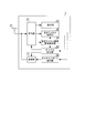
- FIG. 1 is a schematic view showing the configuration of a wireless endoscope system (wireless communication system) in the present embodiment.
- the wireless endoscope system includes an endoscope scope 1 (portable wireless terminal) and a processor 2 (wireless terminal, processor device).
- the endoscope scope 1 and the processor 2 are connected in a mutually communicable state by self-supporting distributed wireless communication in which communication is performed without using a base station, an access point or the like.
- the endoscope 1 is inserted into a body cavity of a patient, takes an image in the body cavity, and wirelessly transmits the taken image to the processor 2.
- the processor 2 receives an image wirelessly transmitted from the endoscope scope 1 and displays the received image on a monitor.
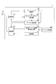
- FIG. 2 is a block diagram showing the configuration of the endoscope scope 1 in the present embodiment.
- the endoscope scope 1 includes an imaging unit 11, a transmission unit 12, an antenna 13, a reception unit 14, an available channel search request transmission unit 15, a network search unit 16, and a channel report detection unit. 17 and a channel setting unit 18.
- the imaging unit 11 performs imaging inside a body cavity, acquires an image, and performs A / D conversion (analog-digital conversion) or the like of acquired image data.
- the transmission unit 12 modulates and transmits a radio signal.
- the antenna 13 transmits and receives radio waves.
- the receiver 14 receives and demodulates a radio signal.
- the free channel search request transmission unit 15 notifies a free channel search request (trigger).
- the network search unit 16 searches for the processor 2 that is the connection destination.
- the channel report detection unit 17 acquires a free channel search result included in the channel report received from the processor 2.
- the channel setting unit 18 sets channels used for transmission and reception of radio signals in the transmission unit 12 and the reception unit 14.
- the available channel search request transmission unit 15 notifies the transmission unit 12 and the network search unit 16 of an available channel search request.
- the network search unit 16 searches for the processor 2 as the connection destination. Specifically, the network search unit 16 searches for a channel in which the processor 2 is open based on a beacon message periodically transmitted after the processor 2 is opened, and indicates a channel in which the processor 2 is open. The information is notified to the channel setting unit 18.
- the channel setting unit 18 transmits the channel used for transmitting and receiving radio signals based on the notified information. Set in section 14.
- the transmission unit 12 modulates the idle channel search request notified from the idle channel search request transmission unit 15, and the idle channel search request to the processor 2 via the antenna 13 in the channel set by the channel setting unit 18. Send Thereafter, the endoscope scope 1 stands by until receiving a channel report transmitted from the processor 2.
- the receiving unit 14 passes the channel report received via the antenna 13 to the channel report detecting unit 17.
- the channel report detection unit 17 obtains a free channel search result included in the channel report, and passes the free channel search result to the channel setting unit 18.
- the channel setting unit 18 sets the channel instructed by the empty channel search result in the transmission unit 12 and the reception unit 14. The free channel will be described later.
- the transmission unit 12 and the reception unit 15 of the endoscope scope 1 use the set channel. Communication with the processor 2 is performed, and the imaging unit 11 transmits the image data captured and modulated to the processor 2.
- FIG. 3 is a block diagram showing the configuration of the processor 2 in the present embodiment.
- the processor 2 includes the antenna 21, the receiving unit 22, the display unit 23, the free channel search request detecting unit 24 (trigger receiving unit), the free channel searching unit 25, and the channel report sending unit 26. , A transmission unit 27, and a channel setting unit 28.
- the antenna 21 transmits and receives radio waves.
- the receiver 22 receives and demodulates a radio signal.
- the display unit 23 performs signal processing on the image data transmitted from the endoscope scope 1 and outputs the image data to the monitor.
- the free channel search request detection unit 24 acquires a free channel search request (trigger) transmitted from the endoscope scope 2.
- the free channel search unit 25 searches for free channels, which are channels not used by other devices.
- the channel report transmission unit 26 modulates a channel report including the search result of the free channel and transmits it to the scope.
- the transmission unit 27 modulates and transmits a radio signal.
- the channel setting unit 28 sets a channel used for transmitting and receiving a radio signal in the receiving unit 22 and the transmitting unit 27.
- the idle channel search unit 25 searches for an idle channel, which is a channel not used by another device, via the antenna 21 and the reception unit 22 after the power supply of the processor is activated.
- the idle channel search unit 25 detects a plurality of idle channels, it selects a channel with the best communication quality from the detected channels.
- the free channel search unit 25 notifies the channel setting unit 28 of free channel information which is a search result of the free channel.
- the channel setting unit 28 sets a channel used by the transmission unit 27 and the reception unit 22 of the processor to transmit and receive a radio signal based on the notified free channel information.
- the processor 2 opens. After opening the station, the processor 2 periodically transmits a beacon including information on a channel used for communication, and stands by until receiving a free channel search request transmitted from the endoscope 1.
- the free channel may be selected on the basis of the interference power measured for each channel, or the number of wireless communication devices and the number of packets communicating in each channel.
- the vacant channel may be selected on the basis of the measured one.
- the idle channel search request detection unit 24 receives the idle channel search request transmitted from the endoscope 1 via the antenna 21 and the reception unit, the idle channel search request detection unit 24 instructs the idle channel search unit 25 to search for an idle channel.
- the free channel search unit 25 searches for a free channel which is a channel not used by another device.
- the idle channel search unit 25 detects a plurality of idle channels, it selects a channel with the best communication quality from the detected channels. Subsequently, the idle channel search unit 25 passes a channel report including information on idle channels to the channel report transmission unit 26, and the channels used by the receiver 22 and the transmitter 27 are idle channels (or idle channels).
- the channel setting unit 28 is instructed to change the channel so as to change the channel to the best communication quality.
- the channel report transmission unit 26 transmits the channel report to the endoscope scope 1 via the transmission unit 27 and the antenna 21. At this time, the transmission unit 27 performs modulation processing and transmission processing.
- the channel setting unit 28 determines that the communication quality is the best among the available channels (or among the available channels) based on the channel change instruction issued from the available channel searching unit 25. Channel) are set in the transmission unit 27 and the reception unit 22.
- the transmitting unit 27 and the receiving unit 22 of the processor 2 Communication is performed, and the image data transmitted from the endoscope 1 is received.
- the display unit 23 of the processor 2 performs signal processing on the received image data, and outputs the processed image data to the monitor.
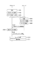
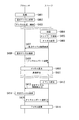
- FIG. 4 is a sequence diagram showing a process flow of the endoscope scope 1 and the processor 2 in the present embodiment.
- the processor 2 performs free channel search (step S102) after activation (step S101), sets a channel to communicate with the endoscope 1 based on the search result, and opens the station ( Step S103). After that, the processor 2 stands by until it receives an idle channel search request transmitted from the endoscope scope 1.
- the endoscope scope 1 performs network search (step S105) after activation (step S104), and based on a beacon message periodically transmitted from the processor 2, The processor 2 to be connected and the channel used for communication with the processor 2 are specified. Subsequently, the endoscope scope 1 sets a channel to be used in communication with the processor 2 as the connection destination (step S106), and sends an idle channel search request to the processor 2 as the connection destination (step S107). Do. Thereafter, the endoscope scope 1 stands by until receiving a channel report transmitted from the processor 2.
- the processor 2 When the processor 2 receives the free channel search request, the processor 2 performs free channel search (step S108) again to specify a free channel. That is, the processor 2 carries out a review of channel selection. Subsequently, the processor 2 transmits a channel report including information indicating an idle channel to the endoscope 1 (step S109), and then a channel for communicating with the endoscope 1 is an idle channel (or an idle channel). Of the channels) (step S110). On the other hand, when the endoscope report 1 also receives the channel report, the channel for communicating with the processor 2 is made a vacant channel (or a channel with the best communication quality among the vacant channels) based on the received channel report. It changes (Step S110).
- step S111 since the channel used between the endoscope scope 1 and the processor 2 is set, the endoscope scope 1 and the processor 2 start communication (step S111).
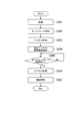
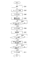
- FIG. 5 is a flow chart showing the operation procedure of the endoscope scope 1 in the present embodiment.
- Step S201 The endoscope scope 1 is activated. Then, it progresses to the process of step S202.
- the network search unit 16 performs a network search, and, based on a beacon message periodically transmitted from the processor 2, identifies the processor 2 as the connection destination and a channel used for communication with the processor 2. Then, it progresses to the process of step S203.
- Step S203 The channel setting unit 18 sets a channel to be used in the communication with the processor 2 as the connection destination specified in step S202. Then, it progresses to the process of step S204.
- Step S204 The free channel search request sending unit 15 sends a free channel search request to the processor 2 of the connection destination determined in step S202, using the channel set in the process of step S203. Then, it progresses to the process of step S205.
- Step S205 If the channel report detection unit 17 receives a channel report from the processor 2, the process proceeds to step S206. Otherwise, the channel report detection unit 17 executes the process of step S205 again. That is, it waits until the channel report detection unit 17 receives a channel report.
- Step S206 The channel setting unit 18 sets, in the transmission unit 12 and the reception unit 14, an idle channel (or a channel with the best communication quality among the idle channels) included in the channel report. Thereafter, the process proceeds to step S207.
- Step S207 The endoscope scope 1 starts communication with the processor 2.
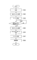
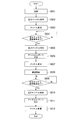
- FIG. 6 is a flowchart showing an operation procedure of the processor 2 in the present embodiment.
- Step S301 The processor 2 starts up. Thereafter, the process proceeds to step S302.
- Step S302 The free channel search unit 25 searches for free channels, and identifies free channels (or channels with the best communication quality among the free channels). Thereafter, the process proceeds to step S303.
- Step S303 The channel setting unit 28 sets the idle channel (or the channel with the best communication quality among the idle channels) identified in step S302 in the transmission unit 27 and the reception unit 22. Thus, the processor 2 opens. Then, it progresses to the process of step S304.
- Step S304 When the free channel search request detection unit 24 receives a free channel search request from the endoscope scope 1, the process proceeds to step S305, and otherwise executes the process of step S304 again. That is, the idle channel search request detection unit 24 waits until the idle channel search request is received.
- Step S305 The free channel search unit 25 searches for free channels and specifies free channels. When a plurality of idle channels are detected, the idle channel search unit 25 selects the channel with the best communication state. Also, the free channel search unit 25 passes a channel report including information on free channels to the channel report transmission unit 26. Thereafter, the process proceeds to step S306. (Step S306) The channel report transmission unit 26 transmits a channel report to the endoscope 1. Thereafter, the process proceeds to the process of step S307.
- Step S307 The channel setting unit 18 sets, in the transmitting unit 12 and the receiving unit 14, the idle channel (or the channel with the best communication quality among the idle channels) detected by the idle channel search unit 25 in step S305. Thereafter, the process proceeds to step S308. (Step S308) The processor 2 initiates communication with the endoscope scope 1.
- the processor 2 of the present embodiment sets a channel to be used when performing communication with the endoscope scope 1 after activation. Also, the endoscope scope 1 transmits a free channel search request to the processor 2 after being activated. In addition, when the processor 2 receives an idle channel search request, the processor 2 searches for an idle channel, and based on the search result, sets a channel to be used when communicating with the endoscope 1 again, and further, the endoscope Send a channel report including the changed channel information to scope 1. In addition, the endoscope scope 1 sets a channel to be used when communicating with the processor 2 based on the channel report.
- FIG. 7 is a block diagram showing the configuration of the endoscope scope 1 in the present embodiment.
- the difference with the configuration of the endoscope scope 1 in the first embodiment is that the endoscope scope 1 in the present embodiment includes an event detection unit 19.
- the endoscope scope 1 includes an imaging unit 11, a transmission unit 12, an antenna 13, a reception unit 14, an available channel search request transmission unit 15, a network search unit 16, and a channel report detection unit.
- a channel setting unit 18 and an event detection unit 19 are provided.
- the imaging unit 11, the transmission unit 12, the antenna 13, the reception unit 14, the free channel search request transmission unit 15, the network search unit 16, the channel report detection unit 17, and the channel setting unit The reference numeral 18 is the same as each part in the first embodiment.
- the event detection unit 19 detects an event for medical examination start that has occurred in the endoscope 1 and notifies the free channel search request transmission unit 15 of information indicating that an event for medical examination start has been detected.
- the free channel search request transmission unit 15 is notified of the information indicating that the event for starting the medical examination is detected from the event detection unit 19, the free channel search request is transmitted to the processor via the transmission unit 12 and the antenna 13. Send to 2
- the event for starting the medical examination is a process executed before starting the medical examination. For example, as detection of an event for the start of a medical examination, a switch depression of the white balance adjustment of an image which is always performed before medical examination may be detected, or a dedicated switch is provided for the operator to reset the channel. The depression may be detected, a result of detection of the operator holding the scope by a switch or a sensor may be detected, or detection of an input of patient information for starting a medical examination may be performed. Moreover, GPS etc. may be provided to acquire position information, and entrance to the examination room may be detected, or the distance between the processor 2 and the endoscope scope 1 may be detected using a laser or a communication device having a short communication distance. It may be detected that it has become a fixed value or less, or it may be detected that a fixed time has elapsed since the power of the endoscope scope 1 is turned on.
- FIG. 8 is a sequence diagram showing a process flow of the endoscope scope 1 and the processor 2 in the present embodiment.
- steps S401 to S411 in the present embodiment is the same processing as the processing of steps S101 to S111 in the first embodiment. In the following description, description of processing similar to that of the first embodiment is omitted.
- step S412 the process after the endoscope scope 1 and the processor 2 start communication, that is, the process after step S412 is added, and therefore, the process from step S412 will be described in order.
- the event detection unit 19 detects an event for starting a medical examination (step S412) after starting communication with the processor 2, the endoscope scope 1 sends a free channel search request to the processor 2 (step S413). ).
- the processor 2 When the processor 2 receives the free channel search request, the processor 2 again performs free channel search (step S414) to specify a free channel.
- the idle channel search unit 25 selects the channel with the best communication state. That is, the processor 2 carries out a review of channel selection.
- the processor 2 transmits a channel report including information indicating an idle channel to the endoscope 1 (step S 415), and then a channel for communicating with the endoscope 1 is an idle channel (or an idle channel). Of the channels) (step S416).
- the channel for communicating with the processor 2 is made a vacant channel (or a channel with the best communication quality among the vacant channels) based on the received channel report. It changes (step S416).
- FIG. 9 is a flow chart showing the operation procedure of the endoscope scope 1 in the present embodiment.
- steps S501 to S507 in the present embodiment is the same processing as the processing of steps S201 to S207 in the first embodiment. In the following description, description of processing similar to that of the first embodiment is omitted.
- step S508 the process after the endoscope scope 1 starts communication with the processor 2, that is, the process after step S508 is added, and therefore, the process from step S508 will be described in order.
- Step S508 If the event detection unit 19 detects an event for starting a medical examination while the endoscope scope 1 and the processor 2 are in communication, the process proceeds to step S509. Otherwise, the process of step S508 is performed. Run again. That is, the process waits until the event detection unit 19 detects an event for starting a medical examination.
- Step S509 The free channel search request sending unit 15 sends a free channel search request to the processor 2. Thereafter, the process proceeds to step S510.
- Step S510 When the channel report detection unit 17 receives a channel report from the processor 2, the process proceeds to the process of step S511, and otherwise executes the process of step S510 again. That is, it waits until the channel report detection unit 17 receives a channel report.
- Step S511 The channel setting unit 18 sets, in the transmission unit 12 and the reception unit 14, an idle channel (or a channel with the best communication quality among the idle channels) included in the channel report.
- FIG. 10 is a flowchart showing the operation procedure of the processor 2 in the present embodiment.
- steps S601 to S608 in the present embodiment are the same as the processes of steps S301 to S308 in the first embodiment. In the following description, description of processing similar to that of the first embodiment is omitted.
- Step S609 When the free channel search request detection unit 24 receives a free channel search request from the endoscope scope 1, the process proceeds to step S610, and otherwise executes the process of step S609 again. That is, the idle channel search request detection unit 24 waits until the idle channel search request is received.
- Step S610 The free channel search unit 25 searches for free channels and specifies free channels. When a plurality of idle channels are detected, the idle channel search unit 25 selects the channel with the best communication state. Also, the free channel search unit 25 passes a channel report including information on free channels to the channel report transmission unit 26. Then, it progresses to the process of step S611. (Step S611) The channel report transmission unit 26 transmits a channel report to the endoscope 1. Thereafter, the process proceeds to step S612.
- Step S612 The channel setting unit 18 sets, in the transmitting unit 12 and the receiving unit 14, the idle channel (or the channel with the best communication quality among the idle channels) detected by the idle channel search unit 25 in step S610.
- the endoscope scope 1 of the present embodiment transmits the free channel search request to the processor 2 again before actually starting the medical examination.
- the processor 2 receives an idle channel search request
- the processor 2 searches for an idle channel, and based on the search result, sets a channel to be used when communicating with the endoscope 1 again, and further, the endoscope Send a channel report including the changed channel information to scope 1.
- the endoscope scope 1 sets a channel to be used when communicating with the processor 2 based on the channel report.
- the endoscope 1 when the endoscope 1 is activated in the storage area and then moved to the medical examination room with the endoscope 1 held, the free channel is re-searched at the time and place where the medical examination is actually started. Since the optimum channel can be assigned, the endoscope scope 1 and the processor 2 can communicate on the more optimum channel.
- the present invention is not limited to this and a plurality of endoscopes may be used. It may be a wireless endoscope system provided with the scope 1.
- the endoscope scope 1 and the processor 2 in the first embodiment and the second embodiment are different from the wireless communication means for transferring image data (for example, an RFID tag reader and the like) Interference can be avoided without providing the RFID and the like.
- image data for example, an RFID tag reader and the like
- crosstalk can be avoided without increasing the cost of the device. That is, as an additional effect, it is possible to avoid the cost increase of the device.
- the wireless terminal of the present invention can change the channel used for communication between wireless terminals after setting the channel used for communication between wireless terminals, better data communication can be performed using a plurality of wireless terminals. It can be carried out.
Abstract
携帯無線端末と自立分散型の無線通信を行う無線端末であって、前記無線端末は、前記携帯無線端末と無線通信を行うチャネルを設定するチャネル設定部と、トリガを受け付けるトリガ受付部と、前記受け付けたトリガに応じて空きチャネルを検索するとともに、当該検索結果により、前記設定されたチャネルを変更する信号を前記チャネル設定部に送出する空きチャネル検索部と、前記携帯無線端末に当該変更を報告する信号を送信する送信部と、を備える。
Description
本発明は、携帯無線端末、無線端末、無線通信システムおよび無線通信方法に関する。
本願は、2009年10月23日に、日本に出願された特願2009-244353号に基づき優先権を主張し、その内容をここに援用する。
本願は、2009年10月23日に、日本に出願された特願2009-244353号に基づき優先権を主張し、その内容をここに援用する。
特許、特許出願、特許公報、科学文献等を以下で引用し明らかにするが、本発明の従来技術をより十分に説明するため、それらの内容をここに援用する。
従来から、医療分野において内視鏡を用いた医療診断が盛んに行われている。内視鏡スコープ(以下、スコープと称する)の挿入部先端にはCCD(Charge Coupled Device、電荷結合素子)などの撮像素子が内蔵されており、このCCDにより撮影された撮像信号に対して、プロセッサで信号処理を施すことで、モニタで体内の画像(内視鏡画像)を観察することができる。スコープとプロセッサとは、通常、信号ケーブルで接続される。
従来から、医療分野において内視鏡を用いた医療診断が盛んに行われている。内視鏡スコープ(以下、スコープと称する)の挿入部先端にはCCD(Charge Coupled Device、電荷結合素子)などの撮像素子が内蔵されており、このCCDにより撮影された撮像信号に対して、プロセッサで信号処理を施すことで、モニタで体内の画像(内視鏡画像)を観察することができる。スコープとプロセッサとは、通常、信号ケーブルで接続される。
一方、スコープとプロセッサ間の接続を無線化した無線内視鏡システムも考案されている。無線内視鏡システムでは、信号ケーブルによる操作の制約が軽減され、操作性が向上する。また、信号ケーブルにより接続された電子内視鏡システムでは、安全性の確保のためにスコープとプロセッサとの間で絶縁する必要があるが、無線内視鏡システムでは、無線化により電気的接続が存在しないため、絶縁に必要な構成が不要となる。しかし、無線内視鏡システムにおいて、プロセッサと複数台の無線内視鏡との間、あるいはプロセッサと他の無線通信機器との間でよりよいデータ通信を行うためには、無線通信による混信を考慮する必要がある。
この対策として、一般的に、自立分散型の無線端末では、通信を開始する前に周囲の電波状態を確認し、混信の影響が低いチャネルを選択して通信を開始する手法がとられている。例えば、プロセッサが、周囲で稼働しているスコープからの使用チャネル報告を定期的に受信し、使用チャネル情報を記憶しておき、ターゲットとなるスコープからチャネル割り当て要求信号を受信した時に未使用チャネルを自動的に割り当て、当該スコープ用のチャネルとして使用する電子内視鏡システムが知られている(例えば、特許文献1参照)。
特許文献1に記載の技術では、プロセッサとスコープとの間で画像の転送に用いるチャネルを一度設定した後、このチャネルを変更することができない。よって、画像の転送に用いるチャネルを一度設定した後、周囲の電波状況などで設定したチャネルでの通信状態が悪化してもそのままそのチャネルで通信し続けなければならない。
本発明は、無線端末間の通信で用いるチャネルを設定した後に、無線端末間の通信で用いるチャネルを変更することができる携帯無線端末、無線端末、無線通信システムおよび無線通信方法を提供する。
携帯無線端末と自立分散型の無線通信を行う無線端末であって、前記無線端末は、前記携帯無線端末と無線通信を行うチャネルを設定するチャネル設定部と、トリガを受け付けるトリガ受付部と、前記受け付けたトリガに応じて空きチャネルを検索するとともに、当該検索結果により、前記設定されたチャネルを変更する信号を前記チャネル設定部に送出する空きチャネル検索部と、前記携帯無線端末に当該変更を報告する信号を送信する送信部と、を備える。
前記チャネル設定部は、前記携帯無線端末から送出される信号を受信するよりも前に、前記チャネルを設定してもよい。
前記空きチャネル検索部は、前記携帯無線端末と前記チャネルを用いて無線通信を行っている間に、前記チャネルを変更する信号を前記チャネル設定部に送出してもよい。
前記トリガ受付部は、前記携帯無線端末から前記トリガを受け付けてもよい。
前記無線端末は、無線内視鏡システムのプロセッサ装置であってもよい。
携帯無線端末と無線通信を行うチャネルを設定するチャネル設定部と、トリガを受け付けるトリガ受付部と、前記受け付けたトリガに応じて空きチャネルを検索するとともに、当該検索結果により、前記設定されたチャネルを変更する信号を前記チャネル設定部に送出する空きチャネル検索部と、前記携帯無線端末に当該変更を報告する信号を送信する送信部とを有する無線端末と、自立分散型の無線通信を行う携帯無線端末であって、前記携帯無線端末は、前記無線端末に対して、当該無線端末に空きチャネルを検索させるためのトリガを送出する送出部を備える。
前記送出部は、前記トリガを前記無線端末と無線通信を開始するときに送出してもよい。
前記送出部は、前記トリガを前記無線端末と無線通信を行っている間に送出してもよい。
前記携帯無線端末は、無線内視鏡システムの内視鏡スコープであってもよい。
携帯無線端末と無線端末とが自立分散型の無線通信を行う無線通信システムであって、前記携帯無線端末は、前記無線端末に対して、当該無線端末に空きチャネルを検索させるためのトリガを送出する送出部を備え、前記無線端末は、前記携帯無線端末と無線通信を行うチャネルを設定するチャネル設定部と、前記携帯無線端末から送出されるトリガを受け付けるトリガ受付部と、前記受け付けたトリガに応じて空きチャネルを検索するとともに、当該検索結果により、前記設定されたチャネルを変更する信号を前記チャネル設定部に送出する空きチャネル検索部と、前記携帯無線端末に当該変更を報告する信号を送信する送信部と、を備える。
前記チャネル設定部は、前記携帯無線端末から送出される信号を受信するよりも前に、前記チャネルを設定してもよい。
前記空きチャネル検索部は、前記携帯無線端末と前記チャネルを用いて無線通信を行っている間に、前記チャネルを変更する信号を前記チャネル設定部に送出してもよい。
携帯無線端末と無線端末とが自立分散型の無線通信を行う無線通信システムの無線通信方法であって、前記無線通信方法は、前記携帯無線端末の送出部が、前記無線端末に対して、当該無線端末に空きチャネルを検索させるためのトリガを送出する送出ステップと、前記無線端末のチャネル設定部が、前記携帯無線端末と無線通信を行うチャネルを設定するチャネル設定ステップと、前記無線端末のトリガ受付部が、前記携帯無線端末から送出されるトリガを受け付けるトリガ受付ステップと、前記無線端末の空きチャネル検索部が、前記受け付けたトリガに応じて空きチャネルを検索するとともに、当該検索結果により、前記設定されたチャネルを変更する信号を前記チャネル設定部に送出する空きチャネル検索ステップと、前記無線端末の送信部が、前記携帯無線端末に当該変更を報告する信号を送信する送信ステップと、を含む。
前記チャネルの設定は、前記携帯無線端末から送出される信号を受信するよりも前に行われてもよい。
前記チャネルを変更する信号の送出は、前記携帯無線端末と前記チャネルを用いて無線通信を行っている間に行われてもよい。
本発明の無線端末は、無線端末間の通信で用いるチャネルを設定した後、トリガを受け付けた場合、空きチャネルを検索し、検索した結果に基づいて設定したチャネルを変更し、さらに他の無線端末にチャネルを変更したことを報告する信号を送出する。そのため、無線端末間の通信で用いるチャネルを設定した後に、無線端末間の通信で用いるチャネルを変更することができる。
(第1の実施形態)
以下、本発明の自立分散型の無線通信システムの第1の実施形態について図面を参照して説明する。なお、実施形態として無線内視鏡システムを用いて説明するが、本発明はこれに限定されるものではなく、自立分散型の無線通信システム(例えば、無線LAN(Local Area Network、構内通信網)、ZigBee(登録商標)(ジグビー)、Bluetooth(登録商標)(ブルートゥース)、ミリ波無線、ボディエリア無線などを用いた無線通信システム)であれば適用可能である。
以下、本発明の自立分散型の無線通信システムの第1の実施形態について図面を参照して説明する。なお、実施形態として無線内視鏡システムを用いて説明するが、本発明はこれに限定されるものではなく、自立分散型の無線通信システム(例えば、無線LAN(Local Area Network、構内通信網)、ZigBee(登録商標)(ジグビー)、Bluetooth(登録商標)(ブルートゥース)、ミリ波無線、ボディエリア無線などを用いた無線通信システム)であれば適用可能である。
図1は、本実施形態における無線内視鏡システム(無線通信システム)の構成を示した概略図である。図示する例では、無線内視鏡システムは、内視鏡スコープ1(携帯無線端末)と、プロセッサ2(無線端末、プロセッサ装置)とを含んでいる。
内視鏡スコープ1とプロセッサ2とは、基地局やアクセスポイントなどを用いずに通信を行う自立分散型の無線通信により、互いに通信が可能な状態で接続している。内視鏡スコープ1は、患者の体腔内に挿入され、体腔内の画像を撮影して、撮影した画像をプロセッサ2に無線伝送する。プロセッサ2は、内視鏡スコープ1から無線伝送された画像を受信して、受信した画像をモニタに表示する。
次に、内視鏡スコープ1の構成について説明する。図2は、本実施形態における内視鏡スコープ1の構成を示したブロック図である。図示する例では、内視鏡スコープ1は、撮像部11と、送信部12と、アンテナ13と、受信部14と、空きチャネル検索要求送出部15と、ネットワーク検索部16と、チャネルレポート検知部17と、チャネル設定部18とを備える。
撮像部11は、体腔内の撮影を行って画像を取得し、取得した画像データのA/D変換(アナログデジタル変換)等を行う。送信部12は、無線信号の変調および送信を行う。アンテナ13は、電波の送受信を行う。受信部14は、無線信号の受信および復調を行う。空きチャネル検索要求送出部15は、空きチャネル検索要求(トリガ)を通知する。ネットワーク検索部16は、接続先となるプロセッサ2を検索する。チャネルレポート検知部17は、プロセッサ2から受信したチャネルレポートに含まれる空きチャネル検索結果を取得する。チャネル設定部18は、無線信号の送受信で使用するチャネルを送信部12と受信部14とに設定する。
次に、内視鏡スコープ1の起動後の動作について説明する。内視鏡スコープ1の電源が起動した後、空きチャネル検索要求送出部15は、送信部12およびネットワーク検索部16に空きチャネル検索要求を通知する。
ネットワーク検索部16は、空きチャネル検索要求が通知された場合、接続先となるプロセッサ2を検索する。具体的には、ネットワーク検索部16は、プロセッサ2が開局した後に定期的に送信するビーコンメッセージに基づいて、プロセッサ2が開局しているチャネルを検索し、プロセッサ2が開局しているチャネルを示す情報をチャネル設定部18に通知する。
チャネル設定部18は、ネットワーク検索部16からプロセッサ2が開局しているチャネルを示す情報が通知された場合、通知された情報に基づいて、無線信号の送受信で使用するチャネルを送信部12および受信部14に設定する。
送信部12は、空きチャネル検索要求送出部15から通知された空きチャネル検索要求を変調し、チャネル設定部18によって設定されたチャネルで、アンテナ13を介して、プロセッサ2に対して空きチャネル検索要求を送信する。その後、内視鏡スコープ1は、プロセッサ2から送信されるチャネルレポートを受信するまで待機状態となる。
次に、プロセッサ2からチャネルレポートが送信された場合における内視鏡スコープ1の動作について説明する。受信部14は、アンテナ13を介して受信したチャネルレポートをチャネルレポート検知部17に渡す。チャネルレポート検知部17は、チャネルレポートに含まれる空きチャネル検索結果を取得し、空きチャネル検索結果をチャネル設定部18に渡す。チャネル設定部18は、空きチャネル検索結果で指示されたチャネルを送信部12および受信部14に設定する。なお、空きチャネルについては後述する。
上述した動作により、内視鏡スコープ1の送信部12および受信部15へのチャネル設定が行われた後、内視鏡スコープ1の送信部12および受信部15は、設定されたチャネルを用いてプロセッサ2と通信を行い、撮像部11が撮影および変調した画像データをプロセッサ2に送信する。
次に、プロセッサ2の構成について説明する。図3は、本実施形態におけるプロセッサ2の構成を示したブロック図である。図示する例では、プロセッサ2は、アンテナ21と、受信部22と、表示部23と、空きチャネル検索要求検知部24(トリガ受付部)と、空きチャネル検索部25と、チャネルレポート送出部26と、送信部27と、チャネル設定部28とを備える。
アンテナ21は、電波の送受信を行う。受信部22は、無線信号の受信および復調を行う。表示部23は、内視鏡スコープ1から送信された画像データに信号処理を施してモニタに出力する。空きチャネル検索要求検知部24は、内視鏡スコープ2から送信された空きチャネル検索要求(トリガ)を取得する。空きチャネル検索部25は、他の装置が使用していないチャネルである空きチャネルを検索する。チャネルレポート送出部26は、空きチャネルの検索結果を含んだチャネルレポートを変調してスコープに送出する。送信部27は、無線信号の変調および送信を行う。チャネル設定部28は、無線信号の送受信で使用するチャネルを受信部22と送信部27とに設定する。
次に、プロセッサ2の起動後の動作について説明する。空きチャネル検索部25は、プロセッサの電源が起動した後に、アンテナ21および受信部22を介して、他の装置が使用していないチャネルである空きチャネルの検索を行う。なお、空きチャネル検索部25は、空きチャネルを複数検出した場合、検出したチャネルの中から通信品質が最も良好なチャネルを選択する。続いて、空きチャネル検索部25は、空きチャネルの検索結果である空きチャネル情報をチャネル設定部28に通知する。チャネル設定部28は、通知された空きチャネル情報に基づいて、プロセッサの送信部27と受信部22とが無線信号の送受信で使用するチャネルの設定を行う。
これにより、プロセッサ2は開局する。プロセッサ2は、開局後、通信で用いるチャネルの情報を含んだビーコンを定期的に送信しながら、内視鏡スコープ1から送信される空きチャネル検索要求を受信するまで待機状態となる。なお、空きチャネル検索部25が行う空きチャネル検索は、チャネルごとに測定した干渉電力を基準として空きチャネルを選択しても良いし、各チャネルで通信を行っている無線通信機器の数やパケット数を測定したものを基準として空きチャネルを選択しても良い。
次に、内視鏡スコープ1から空きチャネル検索要求が送信された場合におけるプロセッサ2の動作について説明する。空きチャネル検索要求検知部24は、アンテナ21および受信部を介して、内視鏡スコープ1から送信された空きチャネル検索要求を受信すると、空きチャネル検索部25に空きチャネルの検索指示を出す。
空きチャネル検索部25は、空きチャネルの検索指示が出された場合、他の装置が使用していないチャネルである空きチャネルを検索する。なお、空きチャネル検索部25は、空きチャネルを複数検出した場合、検出したチャネルの中から通信品質が最も良好なチャネルを選択する。続いて、空きチャネル検索部25は、空きチャネルの情報を含むチャネルレポートをチャネルレポート送出部26に渡すとともに、受信部22と送信部27とが使用するチャネルを空きチャネル(または、空きチャネルのうち通信品質が最も良好なチャネル)に変更するように、チャネル設定部28にチャネルの変更指示を出す。
チャネルレポート送出部26は、送信部27およびアンテナ21を介して、チャネルレポートを内視鏡スコープ1に送出する。このとき、送信部27は変調処理および送信処理を施す。
チャネル設定部28は、チャネルレポート送出部26がチャネルレポートを送出した後、空きチャネル検索部25から出されたチャネルの変更指示に基づいて、空きチャネル(または、空きチャネルのうち通信品質が最も良好なチャネル)を送信部27および受信部22に設定する。
上述した動作により、プロセッサ2の送信部27および受信部22へのチャネル設定が行われた後、プロセッサ2の送信部27および受信部22は、設定されたチャネルを用いて内視鏡スコープ1と通信を行い、内視鏡スコープ1から送信された画像データを受信する。そして、プロセッサ2の表示部23は、受信した画像データに信号処理を施し、モニタに出力する。
次に、本実施形態における内視鏡スコープ1とプロセッサ2の処理の流れについて、図4を用いて説明する。図4は、本実施形態における内視鏡スコープ1とプロセッサ2との処理の流れを示したシーケンス図である。
図示する例では、プロセッサ2は、起動(ステップS101)後に、空きチャネル検索(ステップS102)を行い、検索した結果に基づいて、内視鏡スコープ1と通信を行うチャネルを設定して開局する(ステップS103)。その後、プロセッサ2は、内視鏡スコープ1から送信される空きチャネル検索要求を受信するまで待機状態となる。
また、プロセッサ2が待機状態になった後、内視鏡スコープ1は、起動(ステップS104)後に、ネットワーク検索(ステップS105)を行い、プロセッサ2から定期的に送信されるビーコンメッセージに基づいて、接続先となるプロセッサ2と、プロセッサ2との通信で用いるチャネルとを特定する。続いて、内視鏡スコープ1は、接続先となるプロセッサ2との通信で使用するチャネルを設定(ステップS106)して、接続先のプロセッサ2に対して空きチャネル検索要求を送出(ステップS107)する。その後、内視鏡スコープ1は、プロセッサ2から送信されるチャネルレポートを受信するまで待機状態となる。
プロセッサ2は、空きチャネル検索要求を受信したら、再度、空きチャネル検索(ステップS108)を行い、空いているチャネルを特定する。すなわち、プロセッサ2はチャネル選択の見直しを実施する。続いて、プロセッサ2は、空きチャネルを示す情報を含んだチャネルレポートを内視鏡スコープ1に送信(ステップS109)した後、内視鏡スコープ1と通信を行うチャネルを空きチャネル(または、空きチャネルのうち通信品質が最も良好なチャネル)に変更する(ステップS110)。一方、内視鏡スコープ1も、チャネルレポートを受信した場合、受信したチャネルレポートに基づいて、プロセッサ2と通信を行うチャネルを空きチャネル(または、空きチャネルのうち通信品質が最も良好なチャネル)に変更する(ステップS110)。
これにより、内視鏡スコープ1とプロセッサ2との間で使用するチャネルが設定されるため、内視鏡スコープ1とプロセッサ2とは通信を開始する(ステップS111)。
次に、本実施形態における内視鏡スコープ1の動作手順について説明する。図5は、本実施形態における内視鏡スコープ1の動作手順を示したフローチャートである。
(ステップS201)
内視鏡スコープ1は、起動する。その後、ステップS202の処理に進む。
(ステップS202)
ネットワーク検索部16は、ネットワーク検索を行い、プロセッサ2から定期的に送信されるビーコンメッセージに基づいて、接続先となるプロセッサ2と、プロセッサ2との通信で用いるチャネルとを特定する。その後、ステップS203の処理に進む。
(ステップS203)
チャネル設定部18は、ステップS202で特定した、接続先となるプロセッサ2との通信で用いるチャネルを設定する。その後、ステップS204の処理に進む。
内視鏡スコープ1は、起動する。その後、ステップS202の処理に進む。
(ステップS202)
ネットワーク検索部16は、ネットワーク検索を行い、プロセッサ2から定期的に送信されるビーコンメッセージに基づいて、接続先となるプロセッサ2と、プロセッサ2との通信で用いるチャネルとを特定する。その後、ステップS203の処理に進む。
(ステップS203)
チャネル設定部18は、ステップS202で特定した、接続先となるプロセッサ2との通信で用いるチャネルを設定する。その後、ステップS204の処理に進む。
(ステップS204)
空きチャネル検索要求送出部15は、ステップS203の処理で設定したチャネルを用いて、ステップS202で決定した接続先のプロセッサ2に対して空きチャネル検索要求を送出する。その後、ステップS205の処理に進む。
(ステップS205)
チャネルレポート検知部17は、プロセッサ2からチャネルレポートを受信した場合、ステップS206の処理に進み、それ以外の場合はステップS205の処理を再度実行する。すなわち、チャネルレポート検知部17がチャネルレポートを受信するまで待機する。
空きチャネル検索要求送出部15は、ステップS203の処理で設定したチャネルを用いて、ステップS202で決定した接続先のプロセッサ2に対して空きチャネル検索要求を送出する。その後、ステップS205の処理に進む。
(ステップS205)
チャネルレポート検知部17は、プロセッサ2からチャネルレポートを受信した場合、ステップS206の処理に進み、それ以外の場合はステップS205の処理を再度実行する。すなわち、チャネルレポート検知部17がチャネルレポートを受信するまで待機する。
(ステップS206)
チャネル設定部18は、チャネルレポートに含まれる空きチャネル(または、空きチャネルのうち通信品質が最も良好なチャネル)を送信部12および受信部14に設定する。その後、ステップS207の処理に進む。
(ステップS207)
内視鏡スコープ1は、プロセッサ2と通信を開始する。
チャネル設定部18は、チャネルレポートに含まれる空きチャネル(または、空きチャネルのうち通信品質が最も良好なチャネル)を送信部12および受信部14に設定する。その後、ステップS207の処理に進む。
(ステップS207)
内視鏡スコープ1は、プロセッサ2と通信を開始する。
次に、本実施形態におけるプロセッサ2の動作手順について説明する。図6は、本実施形態におけるプロセッサ2の動作手順を示したフローチャートである。
(ステップS301)
プロセッサ2は、起動する。その後、ステップS302の処理に進む。
(ステップS302)
空きチャネル検索部25は、空きチャネルの検索を行い、空きチャネル(または、空きチャネルのうち通信品質が最も良好なチャネル)を特定する。その後、ステップS303の処理に進む。
(ステップS303)
チャネル設定部28は、ステップS302で特定した空きチャネル(または、空きチャネルのうち通信品質が最も良好なチャネル)を送信部27と受信部22とに設定する。これにより、プロセッサ2は開局する。その後、ステップS304の処理に進む。
プロセッサ2は、起動する。その後、ステップS302の処理に進む。
(ステップS302)
空きチャネル検索部25は、空きチャネルの検索を行い、空きチャネル(または、空きチャネルのうち通信品質が最も良好なチャネル)を特定する。その後、ステップS303の処理に進む。
(ステップS303)
チャネル設定部28は、ステップS302で特定した空きチャネル(または、空きチャネルのうち通信品質が最も良好なチャネル)を送信部27と受信部22とに設定する。これにより、プロセッサ2は開局する。その後、ステップS304の処理に進む。
(ステップS304)
空きチャネル検索要求検知部24は、内視鏡スコープ1から空きチャネル検索要求を受信した場合、ステップS305の処理に進み、それ以外の場合はステップS304の処理を再度実行する。すなわち、空きチャネル検索要求検知部24が空きチャネル検索要求を受信するまで待機する。
空きチャネル検索要求検知部24は、内視鏡スコープ1から空きチャネル検索要求を受信した場合、ステップS305の処理に進み、それ以外の場合はステップS304の処理を再度実行する。すなわち、空きチャネル検索要求検知部24が空きチャネル検索要求を受信するまで待機する。
(ステップS305)
空きチャネル検索部25は、空きチャネルの検索を行い、空きチャネルを特定する。なお、空きチャネル検索部25は、空きチャネルを複数検出した場合、一番通信状態のよいチャネルを選択する。また、空きチャネル検索部25は、空きチャネルの情報を含むチャネルレポートをチャネルレポート送出部26に渡す。その後、ステップS306の処理に進む。
(ステップS306)
チャネルレポート送出部26は、チャネルレポートを内視鏡スコープ1に送出する。その後、ステップS307の処理に進む。
空きチャネル検索部25は、空きチャネルの検索を行い、空きチャネルを特定する。なお、空きチャネル検索部25は、空きチャネルを複数検出した場合、一番通信状態のよいチャネルを選択する。また、空きチャネル検索部25は、空きチャネルの情報を含むチャネルレポートをチャネルレポート送出部26に渡す。その後、ステップS306の処理に進む。
(ステップS306)
チャネルレポート送出部26は、チャネルレポートを内視鏡スコープ1に送出する。その後、ステップS307の処理に進む。
(ステップS307)
チャネル設定部18は、空きチャネル検索部25がステップS305で検出した空きチャネル(または、空きチャネルのうち通信品質が最も良好なチャネル)を、送信部12および受信部14に設定する。その後、ステップS308の処理に進む。
(ステップS308)
プロセッサ2は、内視鏡スコープ1と通信を開始する。
チャネル設定部18は、空きチャネル検索部25がステップS305で検出した空きチャネル(または、空きチャネルのうち通信品質が最も良好なチャネル)を、送信部12および受信部14に設定する。その後、ステップS308の処理に進む。
(ステップS308)
プロセッサ2は、内視鏡スコープ1と通信を開始する。
上述したとおり、本実施形態のプロセッサ2は、起動後に内視鏡スコープ1と通信を行う際に用いるチャネルを設定する。また、内視鏡スコープ1は、起動後に空きチャネル検索要求をプロセッサ2に送信する。また、プロセッサ2は、空きチャネル検索要求を受信した場合、空きチャネルを検索し、検索した結果に基づいて、再度内視鏡スコープ1と通信を行う際に用いるチャネルを設定し、さらに内視鏡スコープ1に対して変更後のチャネルの情報を含んだチャネルレポートを送信する。また、内視鏡スコープ1は、チャネルレポートに基づいて、プロセッサ2と通信を行う際に用いるチャネルを設定する。
これにより、プロセッサ2の起動後、内視鏡スコープ1の起動までの間に無線通信環境が変化していた場合でも、ユーザに適したタイミング、その一例である通信開始やスコープの電源投入時において、プロセッサ2は、空きチャネルの再検索を実施する。そのため、プロセッサ2は、通信に最適なチャネルを割当てることができるので、内視鏡スコープ1とプロセッサ2とは、より最適なチャネルで通信を行うことができる。
(第2の実施形態)
次に、本発明の第2の実施形態について図面を参照して説明する。なお、本実施形態におけるプロセッサ2の構成は、第1の実施形態におけるプロセッサ2の構成と同様である。
次に、本発明の第2の実施形態について図面を参照して説明する。なお、本実施形態におけるプロセッサ2の構成は、第1の実施形態におけるプロセッサ2の構成と同様である。
次に、本実施形態における内視鏡スコープ1の構成について説明する。図7は、本実施形態における内視鏡スコープ1の構成を示したブロック図である。なお、第1の実施形態における内視鏡スコープ1の構成とで異なる点は、本実施形態の内視鏡スコープ1は、イベント検出部19を備えている点である。
図示する例では、内視鏡スコープ1は、撮像部11と、送信部12と、アンテナ13と、受信部14と、空きチャネル検索要求送出部15と、ネットワーク検索部16と、チャネルレポート検知部17と、チャネル設定部18と、イベント検出部19とを備える。なお、本実施形態における撮像部11と、送信部12と、アンテナ13と、受信部14と、空きチャネル検索要求送出部15と、ネットワーク検索部16と、チャネルレポート検知部17と、チャネル設定部18とは、第1の実施形態における各部と同様である。
イベント検出部19は、内視鏡スコープ1で起こった診察開始のためのイベントを検出し、診察開始のためのイベントを検出したことを示す情報を空きチャネル検索要求送出部15に通知する。空きチャネル検索要求送出部15は、イベント検出部19から診察開始のためのイベントを検出したことを示す情報を通知された場合、空きチャネル検索要求を、送信部12およびアンテナ13とを介してプロセッサ2に送信する。
なお、診察開始のためのイベントとは、診察を開始する前に実行される処理である。例えは、診察開始のためのイベントの検出としては、診察前に必ず行う画像のホワイトバランス調整のスイッチ押下を検出してもよいし、術者がチャネルを再設定するための専用のスイッチを設けてその押下を検出してもよいし、術者がスコープを把持したことをスイッチやセンサで検出した結果でもよいし、診察を開始するための患者情報の入力の検出でもよい。また、GPSなどを備えて位置情報を取得し、診察室への入室を検出してもよいし、レーザーや通信距離が短い通信機器などを使ってプロセッサ2と内視鏡スコープ1との距離が一定値以下となったことを検出してもよいし、内視鏡スコープ1の電源を投入後一定時間経過したことを検出してもよい。
次に、本実施形態における内視鏡スコープ1とプロセッサ2の処理の流れについて、図8を用いて説明する。図8は、本実施形態における内視鏡スコープ1とプロセッサ2との処理の流れを示したシーケンス図である。
なお、本実施形態におけるステップS401~ステップS411の処理は、第1の実施形態におけるステップS101~ステップS111の処理と同様の処理である。以下の説明では、第1の実施形態と同様の処理については説明を割愛する。
図示する例では、内視鏡スコープ1とプロセッサ2とが通信を開始した後の処理、すなわち、ステップS412以降の処理が追加されているため、以下、ステップS412の処理から順に説明する。
内視鏡スコープ1は、プロセッサ2と通信を開始した後、イベント検出部19が診察開始のためのイベントを検出(ステップS412)した場合、プロセッサ2に対して空きチャネル検索要求を送出(ステップS413)する。
プロセッサ2は、空きチャネル検索要求を受信したら、再度、空きチャネル検索(ステップS414)を行い、空きチャネルを特定する。なお、空きチャネル検索部25は、空きチャネルを複数検出した場合、一番通信状態のよいチャネルを選択する。すなわち、プロセッサ2はチャネル選択の見直しを実施する。
続いて、プロセッサ2は、空きチャネルを示す情報を含んだチャネルレポートを内視鏡スコープ1に送信(ステップS415)した後、内視鏡スコープ1と通信を行うチャネルを空きチャネル(または、空きチャネルのうち通信品質が最も良好なチャネル)に変更する(ステップS416)。一方、内視鏡スコープ1も、チャネルレポートを受信した場合、受信したチャネルレポートに基づいて、プロセッサ2と通信を行うチャネルを空きチャネル(または、空きチャネルのうち通信品質が最も良好なチャネル)に変更する(ステップS416)。
次に、本実施形態における内視鏡スコープ1の動作手順について説明する。図9は、本実施形態における内視鏡スコープ1の動作手順を示したフローチャートである。
なお、本実施形態におけるステップS501~ステップS507の処理は、第1の実施形態におけるステップS201~ステップS207の処理と同様の処理である。以下の説明では、第1の実施形態と同様の処理については説明を割愛する。
図示する例では、内視鏡スコープ1がプロセッサ2と通信を開始した後の処理、すなわち、ステップS508以降の処理が追加されているため、以下、ステップS508の処理から順に説明する。
(ステップS508)
内視鏡スコープ1とプロセッサ2とが通信を行っている間、イベント検出部19が診察開始のためのイベントを検出した場合、ステップS509の処理に進み、それ以外の場合にはステップS508の処理を再度実行する。すなわち、イベント検出部19が診察開始のためのイベントを検出するまで待機する。
内視鏡スコープ1とプロセッサ2とが通信を行っている間、イベント検出部19が診察開始のためのイベントを検出した場合、ステップS509の処理に進み、それ以外の場合にはステップS508の処理を再度実行する。すなわち、イベント検出部19が診察開始のためのイベントを検出するまで待機する。
(ステップS509)
空きチャネル検索要求送出部15は、プロセッサ2に対して空きチャネル検索要求を送出する。その後、ステップS510の処理に進む。
(ステップS510)
チャネルレポート検知部17は、プロセッサ2からチャネルレポートを受信した場合、ステップS511の処理に進み、それ以外の場合はステップS510の処理を再度実行する。すなわち、チャネルレポート検知部17がチャネルレポートを受信するまで待機する。
空きチャネル検索要求送出部15は、プロセッサ2に対して空きチャネル検索要求を送出する。その後、ステップS510の処理に進む。
(ステップS510)
チャネルレポート検知部17は、プロセッサ2からチャネルレポートを受信した場合、ステップS511の処理に進み、それ以外の場合はステップS510の処理を再度実行する。すなわち、チャネルレポート検知部17がチャネルレポートを受信するまで待機する。
(ステップS511)
チャネル設定部18は、チャネルレポートに含まれる空きチャネル(または、空きチャネルのうち通信品質が最も良好なチャネル)を送信部12および受信部14に設定する。
チャネル設定部18は、チャネルレポートに含まれる空きチャネル(または、空きチャネルのうち通信品質が最も良好なチャネル)を送信部12および受信部14に設定する。
次に、本実施形態におけるプロセッサ2の動作手順について説明する。図10は、本実施形態におけるプロセッサ2の動作手順を示したフローチャートである。
なお、本実施形態におけるステップS601~ステップS608の処理は、第1の実施形態におけるステップS301~ステップS308の処理と同様の処理である。以下の説明では、第1の実施形態と同様の処理については説明を割愛する。
図示する例では、プロセッサ2が内視鏡スコープ1と通信を開始した後の処理、すなわち、ステップS609以降の処理が追加されているため、以下、ステップS609の処理から順に説明する。
(ステップS609)
空きチャネル検索要求検知部24は、内視鏡スコープ1から空きチャネル検索要求を受信した場合、ステップS610の処理に進み、それ以外の場合はステップS609の処理を再度実行する。すなわち、空きチャネル検索要求検知部24が空きチャネル検索要求を受信するまで待機する。
空きチャネル検索要求検知部24は、内視鏡スコープ1から空きチャネル検索要求を受信した場合、ステップS610の処理に進み、それ以外の場合はステップS609の処理を再度実行する。すなわち、空きチャネル検索要求検知部24が空きチャネル検索要求を受信するまで待機する。
(ステップS610)
空きチャネル検索部25は、空きチャネルの検索を行い、空きチャネルを特定する。なお、空きチャネル検索部25は、空きチャネルを複数検出した場合、一番通信状態のよいチャネルを選択する。また、空きチャネル検索部25は、空きチャネルの情報を含むチャネルレポートをチャネルレポート送出部26に渡す。その後、ステップS611の処理に進む。
(ステップS611)
チャネルレポート送出部26は、チャネルレポートを内視鏡スコープ1に送出する。その後、ステップS612の処理に進む。
空きチャネル検索部25は、空きチャネルの検索を行い、空きチャネルを特定する。なお、空きチャネル検索部25は、空きチャネルを複数検出した場合、一番通信状態のよいチャネルを選択する。また、空きチャネル検索部25は、空きチャネルの情報を含むチャネルレポートをチャネルレポート送出部26に渡す。その後、ステップS611の処理に進む。
(ステップS611)
チャネルレポート送出部26は、チャネルレポートを内視鏡スコープ1に送出する。その後、ステップS612の処理に進む。
(ステップS612)
チャネル設定部18は、空きチャネル検索部25がステップS610で検出した空きチャネル(または、空きチャネルのうち通信品質が最も良好なチャネル)を送信部12および受信部14に設定する。
チャネル設定部18は、空きチャネル検索部25がステップS610で検出した空きチャネル(または、空きチャネルのうち通信品質が最も良好なチャネル)を送信部12および受信部14に設定する。
上述したとおり、本実施形態の内視鏡スコープ1は、実際に診察を開始する前に、再度空きチャネル検索要求をプロセッサ2に送信する。また、プロセッサ2は、空きチャネル検索要求を受信した場合、空きチャネルを検索し、検索した結果に基づいて、再度内視鏡スコープ1と通信を行う際に用いるチャネルを設定し、さらに内視鏡スコープ1に対して変更後のチャネルの情報を含んだチャネルレポートを送信する。また、内視鏡スコープ1は、チャネルレポートに基づいて、プロセッサ2と通信を行う際に用いるチャネルを設定する。
これにより、例えば、保管エリアで内視鏡スコープ1を起動した後に内視鏡スコープ1を持ったまま診察室に移動した場合に、実際に診察を始める時および場所で空きチャネルを再検索して最適なチャネルを割当てることができるので、内視鏡スコープ1とプロセッサ2とは、より最適なチャネルで通信を行うことができる。
なお、図9および図10に示したフローチャートでは、通信開始後の処理としてイベント検出処理および空きチャネル検出処理を一度ずつしか記載していないが、2度以上ループして繰り返して処理を行ってもよい。具体的には、図9に示したフローチャートでは、ステップS508からステップS511の処理を繰り返して行ってもよい。また図10に示したフローチャートでは、ステップS609からステップS612の処理を繰り返して行ってもよい。
以上、この発明の第1の実施形態および第2の実施形態について図面を参照して詳述してきたが、これらはあくまで発明の例示であって、具体的な構成はこの実施形態に限られるものではなく、この発明の要旨を逸脱しない範囲の追加、削除、置換及び他の設計等も本発明の精神或いは範囲を逸脱しない範囲で可能である。即ち、本発明は前述した実施形態により限定されるものではなく、請求項の範囲により限定されるものである。
例えば、第1の実施形態および第2の実施形態では、1台の内視鏡スコープ1を備えた無線内視鏡システムの例を用いて説明したが、これに限らず、複数台の内視鏡スコープ1を備えた無線内視鏡システムであってもよい。
また、上述したとおり、第1の実施形態および第2の実施形態における内視鏡スコープ1とプロセッサ2とは、画像データ転送用の無線通信手段とは別の無線通信手段(例えば、RFIDタグリーダとRFIDなど)を備えることなく、混信を回避することができる。これにより、装置のコストアップを行うことなく、混線を回避することができる。すなわち、付随効果として、装置のコストアップを回避することができる。
本発明の無線端末は、無線端末間の通信で用いるチャネルを設定した後に、無線端末間の通信で用いるチャネルを変更することができるため、複数の無線端末を使用して、よりよいデータ通信を行うことができる。
1 内視鏡スコープ
2 プロセッサ
11 撮像部
12 送信部
13 アンテナ
14 受信部
15 空きチャネル検索要求送出部
16 ネットワーク検索部
17 チャネルレポート検知部
18 チャネル設定部
19 イベント検出部
21 アンテナ
22 受信部
23 表示部
24 空きチャネル検索要求検知部
25 空きチャネル検索部
26 チャネルレポート送出部
27 送信部
28 チャネル設定部
2 プロセッサ
11 撮像部
12 送信部
13 アンテナ
14 受信部
15 空きチャネル検索要求送出部
16 ネットワーク検索部
17 チャネルレポート検知部
18 チャネル設定部
19 イベント検出部
21 アンテナ
22 受信部
23 表示部
24 空きチャネル検索要求検知部
25 空きチャネル検索部
26 チャネルレポート送出部
27 送信部
28 チャネル設定部
Claims (15)
- 携帯無線端末と自立分散型の無線通信を行う無線端末であって、
前記携帯無線端末と無線通信を行うチャネルを設定するチャネル設定部と、
トリガを受け付けるトリガ受付部と、
前記受け付けたトリガに応じて空きチャネルを検索するとともに、当該検索結果により、前記設定されたチャネルを変更する信号を前記チャネル設定部に送出する空きチャネル検索部と、
前記携帯無線端末に当該変更を報告する信号を送信する送信部と、
を備える無線端末。 - 前記チャネル設定部は、前記携帯無線端末から送出される信号を受信するよりも前に、前記チャネルを設定する
請求項1に記載の無線端末。 - 前記空きチャネル検索部は、前記携帯無線端末と前記チャネルを用いて無線通信を行っている間に、前記チャネルを変更する信号を前記チャネル設定部に送出する
請求項1に記載の無線端末。 - 前記トリガ受付部は、前記携帯無線端末から前記トリガを受け付ける
請求項1に記載の無線端末。 - 前記無線端末は、無線内視鏡システムのプロセッサ装置である
請求項1に記載の無線端末。 - 携帯無線端末と無線通信を行うチャネルを設定するチャネル設定部と、トリガを受け付けるトリガ受付部と、前記受け付けたトリガに応じて空きチャネルを検索するとともに、当該検索結果により、前記設定されたチャネルを変更する信号を前記チャネル設定部に送出する空きチャネル検索部と、前記携帯無線端末に当該変更を報告する信号を送信する送信部とを有する無線端末と、自立分散型の無線通信を行う携帯無線端末であって、
前記無線端末に対して、当該無線端末に空きチャネルを検索させるためのトリガを送出する送出部
を備える携帯無線端末。 - 前記送出部は、前記トリガを前記無線端末と無線通信を開始するときに送出する
請求項6に記載の携帯無線端末。 - 前記送出部は、前記トリガを前記無線端末と無線通信を行っている間に送出する
請求項6に記載の携帯無線端末。 - 前記携帯無線端末は、無線内視鏡システムの内視鏡スコープである
請求項6に記載の携帯無線端末。 - 携帯無線端末と無線端末とが自立分散型の無線通信を行う無線通信システムであって、
前記携帯無線端末は、
前記無線端末に対して、当該無線端末に空きチャネルを検索させるためのトリガを送出する送出部
を備え、
前記無線端末は、
前記携帯無線端末と無線通信を行うチャネルを設定するチャネル設定部と、
前記携帯無線端末から送出されるトリガを受け付けるトリガ受付部と、
前記受け付けたトリガに応じて空きチャネルを検索するとともに、当該検索結果により、前記設定されたチャネルを変更する信号を前記チャネル設定部に送出する空きチャネル検索部と、
前記携帯無線端末に当該変更を報告する信号を送信する送信部と、
を備える無線通信システム。 - 前記チャネル設定部は、前記携帯無線端末から送出される信号を受信するよりも前に、前記チャネルを設定する
請求項10に記載の無線通信システム。 - 前記空きチャネル検索部は、前記携帯無線端末と前記チャネルを用いて無線通信を行っている間に、前記チャネルを変更する信号を前記チャネル設定部に送出する
請求項10に記載の無線通信システム。 - 携帯無線端末と無線端末とが自立分散型の無線通信を行う無線通信システムの無線通信方法であって、
前記携帯無線端末の送出部が、前記無線端末に対して、当該無線端末に空きチャネルを検索させるためのトリガを送出する送出ステップと、
前記無線端末のチャネル設定部が、前記携帯無線端末と無線通信を行うチャネルを設定するチャネル設定ステップと、
前記無線端末のトリガ受付部が、前記携帯無線端末から送出されるトリガを受け付けるトリガ受付ステップと、
前記無線端末の空きチャネル検索部が、前記受け付けたトリガに応じて空きチャネルを検索するとともに、当該検索結果により、前記設定されたチャネルを変更する信号を前記チャネル設定部に送出する空きチャネル検索ステップと、
前記無線端末の送信部が、前記携帯無線端末に当該変更を報告する信号を送信する送信ステップと、
を含む無線通信方法。 - 前記チャネルの設定は、前記携帯無線端末から送出される信号を受信するよりも前に行われる、
請求項13に記載の無線通信方法。 - 前記チャネルを変更する信号の送出は、前記携帯無線端末と前記チャネルを用いて無線通信を行っている間に行われる、
請求項13に記載の無線通信方法。
Priority Applications (3)
| Application Number | Priority Date | Filing Date | Title |
|---|---|---|---|
| EP10824763.6A EP2478823B1 (en) | 2009-10-23 | 2010-09-28 | Portable wireless terminal, wireless terminal, wireless communication system and wireless communication method |
| CN201080046671.1A CN102686144B (zh) | 2009-10-23 | 2010-09-28 | 便携无线终端、无线终端、无线通信系统和无线通信方法 |
| US13/448,972 US9002285B2 (en) | 2009-10-23 | 2012-04-17 | Portable wireless terminal, wireless terminal, wireless communication system, and wireless communication method |
Applications Claiming Priority (2)
| Application Number | Priority Date | Filing Date | Title |
|---|---|---|---|
| JP2009244353A JP5642373B2 (ja) | 2009-10-23 | 2009-10-23 | 携帯無線端末、無線通信システムおよび携帯無線端末の無線通信方法 |
| JP2009-244353 | 2009-10-23 |
Related Child Applications (1)
| Application Number | Title | Priority Date | Filing Date |
|---|---|---|---|
| US13/448,972 Continuation US9002285B2 (en) | 2009-10-23 | 2012-04-17 | Portable wireless terminal, wireless terminal, wireless communication system, and wireless communication method |
Publications (1)
| Publication Number | Publication Date |
|---|---|
| WO2011048914A1 true WO2011048914A1 (ja) | 2011-04-28 |
Family
ID=43900152
Family Applications (1)
| Application Number | Title | Priority Date | Filing Date |
|---|---|---|---|
| PCT/JP2010/066786 WO2011048914A1 (ja) | 2009-10-23 | 2010-09-28 | 携帯無線端末、無線端末、無線通信システムおよび無線通信方法 |
Country Status (5)
| Country | Link |
|---|---|
| US (1) | US9002285B2 (ja) |
| EP (1) | EP2478823B1 (ja) |
| JP (1) | JP5642373B2 (ja) |
| CN (1) | CN102686144B (ja) |
| WO (1) | WO2011048914A1 (ja) |
Cited By (2)
| Publication number | Priority date | Publication date | Assignee | Title |
|---|---|---|---|---|
| WO2012017755A1 (ja) * | 2010-08-04 | 2012-02-09 | オリンパス株式会社 | 無線画像通信システムおよび無線画像通信装置 |
| WO2016072174A1 (ja) * | 2014-11-07 | 2016-05-12 | ソニー株式会社 | 通信制御装置、通信制御方法、プログラム及び通信制御システム |
Families Citing this family (6)
| Publication number | Priority date | Publication date | Assignee | Title |
|---|---|---|---|---|
| JP2013150191A (ja) * | 2012-01-20 | 2013-08-01 | Nec Corp | 無線通信装置、無線通信システム、無線通信方法、及び使用周波数決定方法 |
| JP6395445B2 (ja) * | 2014-05-28 | 2018-09-26 | オリンパス株式会社 | 内視鏡、受信装置、無線内視鏡システム、画像受信装置の作動方法、およびプログラム |
| JP6878574B2 (ja) * | 2016-09-09 | 2021-05-26 | エンテラス メディカル インコーポレイテッドEntellus Medical,Inc. | 無線内視鏡 |
| JP7048628B2 (ja) | 2016-11-28 | 2022-04-05 | アダプティブエンドウ エルエルシー | 分離可能使い捨てシャフト付き内視鏡 |
| CN109167978A (zh) * | 2018-10-30 | 2019-01-08 | 衡阳师范学院 | 一种多信道网络监控设备及监控方法 |
| USD1018844S1 (en) | 2020-01-09 | 2024-03-19 | Adaptivendo Llc | Endoscope handle |
Citations (5)
| Publication number | Priority date | Publication date | Assignee | Title |
|---|---|---|---|---|
| JP2005006082A (ja) * | 2003-06-12 | 2005-01-06 | Ntt Docomo Inc | 無線チャネル割り当て制御装置及び無線チャネル割り当て制御方法 |
| JP2006271432A (ja) | 2005-03-28 | 2006-10-12 | Fujinon Corp | 電子内視鏡装置 |
| JP2007167649A (ja) * | 2005-12-19 | 2007-07-05 | General Electric Co <Ge> | 携帯型イメージングのためのシステム、装置及び方法 |
| WO2008069245A1 (ja) * | 2006-12-07 | 2008-06-12 | Mitsubishi Electric Corporation | 無線通信システム、無線端末局、無線基地局および無線通信方法 |
| JP2009244353A (ja) | 2008-03-28 | 2009-10-22 | Nec Corp | カメラモジュール及びカメラモジュールの製造方法 |
Family Cites Families (37)
| Publication number | Priority date | Publication date | Assignee | Title |
|---|---|---|---|---|
| JPS5411607A (en) * | 1977-06-27 | 1979-01-27 | Fujitsu Ltd | Selection system for radio line |
| US6167260A (en) * | 1996-01-31 | 2000-12-26 | Motorola, Inc. | Method for demand channel change for a radio telephone |
| JP3220646B2 (ja) * | 1996-09-13 | 2001-10-22 | シャープ株式会社 | コードレス電話機 |
| JP2002354147A (ja) * | 2001-05-29 | 2002-12-06 | Sanyo Electric Co Ltd | コミュニケーション端末装置 |
| US8401262B2 (en) * | 2001-06-20 | 2013-03-19 | Given Imaging, Ltd | Device, system and method for motility measurement and analysis |
| US7724928B2 (en) * | 2001-06-20 | 2010-05-25 | Given Imaging, Ltd. | Device, system and method for motility measurement and analysis |
| JP2003244761A (ja) * | 2002-02-14 | 2003-08-29 | Fujitsu Ltd | 通信装置、通信システム及び通信周波数設定方法 |
| JP2003265402A (ja) * | 2002-03-13 | 2003-09-24 | Fuji Photo Optical Co Ltd | 腹腔鏡装置 |
| JP2006509574A (ja) * | 2002-12-16 | 2006-03-23 | ギブン イメージング リミテッド | 生体内センサの選択的作動のための装置、システム、及び方法 |
| US8206285B2 (en) * | 2003-12-31 | 2012-06-26 | Given Imaging Ltd. | Apparatus, system and method to indicate in-vivo device location |
| WO2005062716A2 (en) * | 2003-12-31 | 2005-07-14 | Given Imaging Ltd. | Apparatus, system and method to indicate in-vivo device location |
| US8394034B2 (en) * | 2004-05-21 | 2013-03-12 | Given Imaging Ltd. | Device, system and method for in-vivo sampling |
| US7938775B2 (en) * | 2004-06-28 | 2011-05-10 | Given Imaging, Ltd. | Device, system, and method for in-vivo analysis |
| US8738106B2 (en) * | 2005-01-31 | 2014-05-27 | Given Imaging, Ltd | Device, system and method for in vivo analysis |
| JP2008528170A (ja) * | 2005-01-31 | 2008-07-31 | ギブン・イメージング・リミテツド | 生体内分析用デバイス、装置および方法 |
| US20060217593A1 (en) * | 2005-03-24 | 2006-09-28 | Zvika Gilad | Device, system and method of panoramic multiple field of view imaging |
| US8790248B2 (en) * | 2005-07-20 | 2014-07-29 | Olympus Medical Systems Corp. | Indwelling apparatus for body cavity introducing device and body cavity introducing device placing system |
| JP4398414B2 (ja) | 2005-08-19 | 2010-01-13 | オリンパス株式会社 | 受信装置 |
| KR20070027844A (ko) * | 2005-08-29 | 2007-03-12 | 삼성전자주식회사 | 무선통신 시스템에서 채널품질 정보를 전송하기 위한 방법및 장치 |
| WO2007034891A1 (ja) * | 2005-09-22 | 2007-03-29 | Olympus Corporation | 受信装置 |
| JP5313689B2 (ja) * | 2005-12-29 | 2013-10-09 | ギブン イメージング リミテッド | 生体内検知デバイスの位置を決定するためのシステムおよびシステムの作動方法 |
| EP2013795A2 (en) * | 2006-04-03 | 2009-01-14 | Given Imaging Ltd. | Device, system and method for in-vivo analysis |
| JP2009532168A (ja) * | 2006-04-03 | 2009-09-10 | ギブン イメージング リミテッド | 生体内分析のための装置、システムおよび方法 |
| US8335362B2 (en) * | 2006-06-12 | 2012-12-18 | Given Imaging Ltd. | Device, system and method for measurement and analysis of contractile activity |
| CA2676407A1 (en) * | 2007-02-01 | 2008-08-07 | Proteus Biomedical, Inc. | Ingestible event marker systems |
| JP5025720B2 (ja) * | 2007-02-22 | 2012-09-12 | オリンパスメディカルシステムズ株式会社 | 被検体内導入システム |
| ATE539553T1 (de) * | 2007-02-26 | 2012-01-15 | Olympus Medical Systems Corp | Kapselendoskop |
| US9339174B2 (en) * | 2007-07-18 | 2016-05-17 | Given Imaging Ltd | Device and method for viewing a body lumen |
| JP5594711B2 (ja) * | 2008-02-26 | 2014-09-24 | ギブン イメージング リミテッド | 生体内画像コントラストを強化するための方法 |
| US8406490B2 (en) * | 2008-04-30 | 2013-03-26 | Given Imaging Ltd. | System and methods for determination of procedure termination |
| US8358981B1 (en) * | 2008-10-29 | 2013-01-22 | University Of South Florida | Minimally invasive networked surgical system and method |
| JP5144485B2 (ja) * | 2008-12-12 | 2013-02-13 | オリンパス株式会社 | 無線通信端末 |
| JP5558033B2 (ja) * | 2009-06-10 | 2014-07-23 | オリンパス株式会社 | 無線内視鏡装置およびその受信装置、受信方法、受信プログラム |
| JP5635252B2 (ja) * | 2009-10-22 | 2014-12-03 | オリンパス株式会社 | 画像送信装置、画像通信システム、画像送信方法、およびプログラム |
| WO2011068000A1 (ja) * | 2009-12-04 | 2011-06-09 | オリンパスメディカルシステムズ株式会社 | 手持式無線内視鏡 |
| JP5945384B2 (ja) * | 2010-08-04 | 2016-07-05 | オリンパス株式会社 | 無線画像通信システム、受信機、送信機、およびプログラム |
| WO2013058277A1 (ja) * | 2011-10-21 | 2013-04-25 | オリンパスメディカルシステムズ株式会社 | アンテナ接続ユニット、受信装置、受信強度補正装置、カプセル型内視鏡システム、補正方法およびプログラム |
-
2009
- 2009-10-23 JP JP2009244353A patent/JP5642373B2/ja active Active
-
2010
- 2010-09-28 WO PCT/JP2010/066786 patent/WO2011048914A1/ja active Application Filing
- 2010-09-28 CN CN201080046671.1A patent/CN102686144B/zh active Active
- 2010-09-28 EP EP10824763.6A patent/EP2478823B1/en not_active Not-in-force
-
2012
- 2012-04-17 US US13/448,972 patent/US9002285B2/en active Active
Patent Citations (5)
| Publication number | Priority date | Publication date | Assignee | Title |
|---|---|---|---|---|
| JP2005006082A (ja) * | 2003-06-12 | 2005-01-06 | Ntt Docomo Inc | 無線チャネル割り当て制御装置及び無線チャネル割り当て制御方法 |
| JP2006271432A (ja) | 2005-03-28 | 2006-10-12 | Fujinon Corp | 電子内視鏡装置 |
| JP2007167649A (ja) * | 2005-12-19 | 2007-07-05 | General Electric Co <Ge> | 携帯型イメージングのためのシステム、装置及び方法 |
| WO2008069245A1 (ja) * | 2006-12-07 | 2008-06-12 | Mitsubishi Electric Corporation | 無線通信システム、無線端末局、無線基地局および無線通信方法 |
| JP2009244353A (ja) | 2008-03-28 | 2009-10-22 | Nec Corp | カメラモジュール及びカメラモジュールの製造方法 |
Non-Patent Citations (1)
| Title |
|---|
| See also references of EP2478823A4 |
Cited By (7)
| Publication number | Priority date | Publication date | Assignee | Title |
|---|---|---|---|---|
| WO2012017755A1 (ja) * | 2010-08-04 | 2012-02-09 | オリンパス株式会社 | 無線画像通信システムおよび無線画像通信装置 |
| US9160985B2 (en) | 2010-08-04 | 2015-10-13 | Olympus Corporation | Wireless image communication system and wireless image communication apparatus |
| WO2016072174A1 (ja) * | 2014-11-07 | 2016-05-12 | ソニー株式会社 | 通信制御装置、通信制御方法、プログラム及び通信制御システム |
| JPWO2016072174A1 (ja) * | 2014-11-07 | 2017-08-31 | ソニー株式会社 | 通信制御装置、通信制御方法、プログラム及び通信制御システム |
| US10368257B2 (en) | 2014-11-07 | 2019-07-30 | Sony Corporation | Communication control device, communication control method, program, and communication control system |
| US10798595B2 (en) | 2014-11-07 | 2020-10-06 | Sony Corporation | Communication control device, communication control method, program, and communication control system |
| US11490276B2 (en) | 2014-11-07 | 2022-11-01 | Sony Corporation | Communication control device, communication control method, program, and communication control system |
Also Published As
| Publication number | Publication date |
|---|---|
| US9002285B2 (en) | 2015-04-07 |
| EP2478823A1 (en) | 2012-07-25 |
| JP5642373B2 (ja) | 2014-12-17 |
| CN102686144A (zh) | 2012-09-19 |
| CN102686144B (zh) | 2015-09-02 |
| EP2478823A4 (en) | 2012-10-24 |
| US20120202433A1 (en) | 2012-08-09 |
| JP2011087798A (ja) | 2011-05-06 |
| EP2478823B1 (en) | 2014-05-14 |
Similar Documents
| Publication | Publication Date | Title |
|---|---|---|
| WO2011048914A1 (ja) | 携帯無線端末、無線端末、無線通信システムおよび無線通信方法 | |
| EP2322086B1 (en) | Radiation imaging system, method for radiation imaging system, computer-executable program, and computer-readable storage medium | |
| JP4232043B2 (ja) | ベース装置、無線通信チャンネル切り替え方法および無線通信チャンネル切り替えプログラム | |
| JP5144485B2 (ja) | 無線通信端末 | |
| CN103053210B (zh) | 无线图像通信系统以及无线图像通信装置 | |
| EP2441380B1 (en) | Wireless endoscopic apparatus, receiving device thereof, and receiving method | |
| US9374842B2 (en) | Proxy communication system and proxy communication system controlling method in BAN environment | |
| US20100118848A1 (en) | Communication terminal and image data transfer method | |
| US9264841B2 (en) | Wireless communication apparatus, wireless communication system, wireless communication method, X-ray sensor, and program storage medium | |
| WO2017110297A1 (en) | Information processing device, information processing method, and program | |
| EP3344001B1 (en) | Information processing device, information processing method, and program | |
| EP3893467B1 (en) | Wireless device | |
| WO2021090404A1 (ja) | 超音波プローブ、超音波診断システム、超音波診断プログラム、超音波診断方法 | |
| JP2022169228A (ja) | ワイヤレス超音波画像診断装置 | |
| JP2010193238A (ja) | 無線通信システムおよび無線通信方法 | |
| JP2017069880A (ja) | 撮影装置 | |
| JP2007174265A (ja) | ワイヤレスlanシステム、ステーション端末装置およびクレードル | |
| JP2010245813A (ja) | 移動端末、移動体通信システム、並びに基地局サーチ方法及びプログラム | |
| JP2014170987A (ja) | 管理システム、管理方法、及び無線端末 |
Legal Events
| Date | Code | Title | Description |
|---|---|---|---|
| WWE | Wipo information: entry into national phase |
Ref document number: 201080046671.1 Country of ref document: CN |
|
| 121 | Ep: the epo has been informed by wipo that ep was designated in this application |
Ref document number: 10824763 Country of ref document: EP Kind code of ref document: A1 |
|
| WWE | Wipo information: entry into national phase |
Ref document number: 2010824763 Country of ref document: EP |