WO2011048748A1 - 眼底画像処理装置及び眼底観察装置 - Google Patents
眼底画像処理装置及び眼底観察装置 Download PDFInfo
- Publication number
- WO2011048748A1 WO2011048748A1 PCT/JP2010/005633 JP2010005633W WO2011048748A1 WO 2011048748 A1 WO2011048748 A1 WO 2011048748A1 JP 2010005633 W JP2010005633 W JP 2010005633W WO 2011048748 A1 WO2011048748 A1 WO 2011048748A1
- Authority
- WO
- WIPO (PCT)
- Prior art keywords
- fundus
- image
- cross
- sectional position
- sectional
- Prior art date
- Legal status (The legal status is an assumption and is not a legal conclusion. Google has not performed a legal analysis and makes no representation as to the accuracy of the status listed.)
- Ceased
Links
Images




Classifications
-
- A—HUMAN NECESSITIES
- A61—MEDICAL OR VETERINARY SCIENCE; HYGIENE
- A61B—DIAGNOSIS; SURGERY; IDENTIFICATION
- A61B3/00—Apparatus for testing the eyes; Instruments for examining the eyes
- A61B3/10—Objective types, i.e. instruments for examining the eyes independent of the patients' perceptions or reactions
- A61B3/102—Objective types, i.e. instruments for examining the eyes independent of the patients' perceptions or reactions for optical coherence tomography [OCT]
Definitions
- the present invention relates to a fundus image processing apparatus that processes a fundus photographed image obtained by photographing the fundus and a three-dimensional image of the fundus formed using optical coherence tomography (OCT), and
- OCT optical coherence tomography
- the present invention relates to a fundus observation apparatus capable of forming a fundus photographed image and / or a three-dimensional image of the fundus.
- OCT that forms an image representing the surface form and internal form of an object to be measured using a light beam from a laser light source or the like has attracted attention. Since OCT has no invasiveness to the human body like X-ray CT, it is expected to be applied particularly in the medical field and the biological field. For example, in the field of ophthalmology, an apparatus for forming an image of the fundus oculi, cornea, etc. has entered a practical stage.
- Patent Document 1 discloses an apparatus to which OCT is applied.
- the measuring arm scans an object with a rotary turning mirror (galvanomirror)
- a reference mirror is installed on the reference arm
- the intensity of the interference light of the light beam from the measuring arm and the reference arm is dispersed at the exit.
- An interferometer is provided for analysis by the instrument.
- the reference arm is configured to change the phase of the reference light beam stepwise by a discontinuous value.
- Patent Document 1 uses a so-called “Fourier Domain OCT (Fourier Domain OCT)” technique.
- Fourier Domain OCT Frier Domain OCT
- a low-coherence beam is irradiated onto the object to be measured, the reflected light and the reference light are superimposed to generate interference light, and the spectral intensity distribution of the interference light is acquired and subjected to Fourier transform.
- the form of the object to be measured in the depth direction (z direction) is imaged.
- this type of technique is also called a spectral domain.
- the apparatus described in Patent Document 1 includes a galvanometer mirror that scans a light beam (signal light), thereby forming an image of a desired measurement target region of the object to be measured. Since this apparatus is configured to scan the light beam only in one direction (x direction) orthogonal to the z direction, the image formed by this apparatus is in the scanning direction (x direction) of the light beam. It becomes a two-dimensional tomogram in the depth direction (z direction) along.
- a plurality of two-dimensional tomographic images in the horizontal direction are formed by scanning (scanning) the signal light in the horizontal direction (x direction) and the vertical direction (y direction), and based on the plurality of tomographic images.
- a technique for acquiring and imaging three-dimensional tomographic information of a measurement range is disclosed. Examples of the three-dimensional imaging include a method of displaying a plurality of tomographic images side by side in a vertical direction (referred to as stack data) and a method of rendering a plurality of tomographic images to form a three-dimensional image. Conceivable.
- Patent Documents 3 and 4 disclose other types of OCT apparatuses.
- Patent Document 3 scans the wavelength of light applied to an object to be measured, acquires a spectral intensity distribution based on interference light obtained by superimposing reflected light of each wavelength and reference light
- an OCT apparatus for imaging the form of an object to be measured by performing Fourier transform on the object is described.
- Such an OCT apparatus is called a swept source type.
- the swept source type is a kind of Fourier domain type.
- Patent Document 4 the traveling direction of light is obtained by irradiating the object to be measured with light having a predetermined beam diameter, and analyzing the component of interference light obtained by superimposing the reflected light and the reference light.
- An OCT apparatus for forming an image of an object to be measured in a cross-section orthogonal to is described. Such an OCT apparatus is called a full-field type or an en-face type.
- Patent Document 5 discloses a configuration in which OCT is applied to the ophthalmic field.
- fundus cameras, slit lamps, and the like Prior to the application of OCT, fundus cameras, slit lamps, and the like have been used as devices for observing the eye to be examined (see, for example, Patent Document 6 and Patent Document 7).
- a fundus camera is a device that shoots the fundus by illuminating the subject's eye with illumination light and receiving the fundus reflection light.
- a slit lamp is a device that acquires an image of a cross-section of the cornea by cutting off a light section of the cornea using slit light.
- An apparatus using OCT has an advantage over a fundus camera or the like in that a high-definition image can be acquired, and further, a tomographic image or a three-dimensional image can be acquired.
- an apparatus using OCT can be applied to observation of various parts of an eye to be examined and can acquire high-definition images, it has been applied to diagnosis of various ophthalmic diseases.
- a diagnostic method that grasps changes over time in the state of an attention site (affected area, characteristic site, etc.) by comparing images acquired at different timings.
- comparative observation is performed in the diagnosis of glaucoma and macular diseases.
- the physical quantity related to the target region may be quantitatively compared. Examples of physical quantities to be compared include the size of the affected area (radius, diameter, area, volume, etc.), the cup size of the optic nerve head, the disk size, and the rim size.
- the present invention has been made to solve the above-described problems, and an object of the present invention is to provide a fundus image processing apparatus and a fundus oculi observation apparatus that can perform fundus comparative observation with high accuracy. .
- the invention according to claim 1 includes a first fundus photographed image of the eye to be examined and a first three-dimensional image of the fundus of the eye to be examined, which are obtained at the first examination timing.
- Storage means for preliminarily storing a second fundus photographed image of the eye to be examined and a second three-dimensional image of the fundus acquired at a second examination timing different from the first examination timing;
- First calculating means for calculating a positional shift amount between the first fundus photographic image and the second fundus photographic image in the fundus surface direction based on the fundus photographic image and the second fundus photographic image;
- Designating means for designating a cross-sectional position at substantially the same position on the fundus described in each of the first fundus photographed image and the second fundus photographed image based on the calculated positional deviation amount; Corresponding to the cross-sectional position designated in the first fundus image.
- the invention according to claim 2 is the fundus image processing apparatus according to claim 1, wherein the specifying unit specifies a plurality of the cross-sectional positions, and the second calculating unit includes the plurality of cross-sectional positions.
- the cross-sectional positions of the first and second three-dimensional images corresponding to the cross-sectional positions are set to the designated cross-sectional positions based on the first tomographic image and the second tomographic image at the cross-sectional positions.
- the tilt displacement amount in a plane stretched between a direction along the depth direction and the fundus depth direction is calculated.
- the invention according to claim 3 is the fundus image processing apparatus according to claim 2, wherein the designation means is a pair of linear cross-sectional positions intersecting at right angles as the plurality of cross-sectional positions.
- the second calculation means calculates the amount of inclination deviation for the cross-sectional positions of the first and second three-dimensional images corresponding to the pair of cross-sectional positions, respectively.
- the invention according to claim 4 is the fundus image processing apparatus according to claim 2, wherein the designation means has two or more straight lines that are arranged radially and intersect with each other as the plurality of cross-sectional positions. A second cross-sectional position is calculated, and the second calculating unit calculates the amount of inclination deviation for the cross-sectional positions of the first and second three-dimensional images corresponding to the two or more cross-sectional positions, The maximum value of the inclination deviation amounts corresponding to the two or more cross-sectional positions calculated by the second calculation means is selected, and the inclination deviation amount is set so as to cancel the selected inclination deviation amount.
- Correction means for correcting a deviation in inclination between the first three-dimensional image and the second three-dimensional image in a plane stretched by the direction along the corresponding cross-sectional position and the depth direction of the fundus. It is characterized by.
- the invention according to claim 5 is the fundus image processing apparatus according to any one of claims 1 to 3, wherein the positional deviation amount calculated by the first calculation unit and the positional deviation amount are calculated.
- Alignment means for performing alignment between the first three-dimensional image and the second three-dimensional image so as to cancel out the tilt deviation amount calculated by the second calculation means; It is characterized by.
- the invention according to claim 6 is the fundus image processing apparatus according to any one of claims 1 to 3, wherein the positional deviation amount calculated by the first calculation means and / or Based on the amount of tilt deviation calculated by the second calculation means, the first three-dimensional image is analyzed to calculate a first value of a predetermined physical quantity, and the second three-dimensional image And analyzing means for calculating the second value of the predetermined physical quantity.
- the invention according to claim 7 is the fundus image processing apparatus according to claim 1, wherein the first calculation means uses the parallel movement amount and rotational movement in the fundus surface direction as the positional deviation amount. And calculating the quantity.
- the invention according to claim 8 is an imaging means for imaging the fundus of the subject's eye, and the low-coherence light is divided into signal light and reference light, and the signal light passing through the fundus and the reference light path are passed through.
- An optical system that generates and detects interference light by superimposing reference light, an image forming unit that forms a three-dimensional image of the fundus based on the detection result of the interference light, and the imaging at a first examination timing A first fundus photographed image of the eye to be examined photographed by means, a first three-dimensional image of the fundus formed by the image forming means, and a second examination timing different from the first examination timing.
- Storage means for storing the photographed second fundus photographed image of the subject eye and the formed second three-dimensional image of the fundus, the first fundus photographed image, and the second fundus photographed image Based on the fundus surface direction
- First calculation means for calculating a positional deviation amount between the first fundus photographic image and the second fundus photographic image, and the first fundus imaging based on the calculated positional deviation amount.
- Designating means for designating a cross-sectional position at substantially the same position on the fundus depicted in each of the image and the second fundus photographed image, and the first corresponding to the cross-sectional position designated in the first fundus photographed image
- a second calculating unit configured to calculate an inclination shift amount between the first tomographic image and the second tomographic image on a plane stretched by the direction along the designated cross-sectional position and the fundus depth direction; And a fundus oculi observation device.
- the invention according to claim 9 divides low-coherence light into signal light and reference light, and superimposes the signal light passing through the fundus of the eye to be examined and the reference light passing through the reference light path to interfere light.
- An optical system that generates and detects the image, an image forming unit that forms a three-dimensional image of the fundus oculi based on the detection result of the interference light, and a first fundus of the eye to be examined acquired at a first examination timing
- a photographed image and a second fundus photographed image of the eye to be examined acquired at a second examination timing different from the first examination timing are stored in advance, and at the first examination timing, by the image forming unit.
- Storage means for storing the formed first three-dimensional image of the fundus and the formed second three-dimensional image of the fundus at the second examination timing; the first fundus image; Based on the second fundus image
- a first calculating means for calculating a positional shift amount between the first fundus captured image and the second fundus captured image in the fundus surface direction, and based on the calculated positional shift amount, Designating means for designating a cross-sectional position at substantially the same position on the fundus depicted in each of the first fundus photographed image and the second fundus photographed image, and a cross-sectional position designated in the first fundus photographed image
- a second tomographic image at a cross-sectional position of the second three-dimensional image corresponding to the cross-sectional position designated by the second fundus image.
- An inclination shift amount between the first tomographic image and the second tomographic image on a plane stretched by the direction along the designated cross-sectional position and the depth direction of the fundus is calculated based on the tomographic image of the first tomographic image.
- An eye comprising: a second calculating means; It is an observation device.
- the invention described in claim 10 is different from the imaging means for imaging the fundus of the eye to be examined, the first three-dimensional image of the fundus acquired at the first examination timing, and the first examination timing.
- a second three-dimensional image of the fundus acquired at the second examination timing is stored in advance, and a first fundus photographed image of the eye to be examined photographed by the photographing means at the first examination timing
- Storage means for storing a second fundus photographed image of the subject eye photographed at the second examination timing, and a fundus oculi based on the first fundus photographed image and the second fundus photographed image.
- First calculation means for calculating a positional deviation amount between the first fundus photographic image and the second fundus photographic image in the surface direction, and based on the calculated positional deviation amount, the first Fundus photographed image and second fundus photographed image
- Designating means for designating a cross-sectional position at substantially the same position on the fundus depicted in each of the first and three-dimensional images in the cross-sectional position of the first three-dimensional image corresponding to the cross-sectional position designated in the first fundus image
- a second calculating means for calculating an amount of inclination deviation between the first tomographic image and the second tomographic image on a plane stretched by the direction along the direction of the fundus depth. It is an observation device.
- the present invention it is possible to obtain the positional deviation amount and the inclination deviation amount that are interposed between images to be compared in comparative observation of the fundus. Therefore, by performing comparative observation with reference to the obtained positional deviation amount and inclination deviation amount, it is possible to compare the images to be compared as those acquired under substantially the same conditions. This makes it possible to perform comparative observation of the fundus with high accuracy.
- This fundus oculi observation device is equipped with this fundus image processing device. That is, this fundus oculi observation device acquires part or all of an image to be subjected to processing by the fundus image processing device.
- this fundus oculi observation device acquires part or all of an image to be subjected to processing by the fundus image processing device.
- a fundus oculi observation device will be described in detail.
- the fundus oculi observation device forms a tomographic image or a three-dimensional image of the fundus using OCT.
- images acquired by OCT may be collectively referred to as OCT images.
- a measurement operation for forming an OCT image may be referred to as OCT measurement.
- a fundus oculi observation device capable of acquiring both a fundus OCT image and a fundus photographed image is taken up as in the device disclosed in Patent Document 5.
- the fundus oculi observation device may be configured to acquire only one of an OCT image and a fundus photographic image. That is, the present invention also includes the following two types of devices: (1) A fundus observation device (OCT device) that can acquire only an OCT image by itself, and other devices (fundus camera, slit lamp microscope) (Slit lamp), configured to receive the fundus photographic image acquired by a scanning laser ophthalmoscope (SLO (Scanning Laser Ophthalmoscope), etc.) and memorize it; (2) Only the fundus photographic image itself A fundus observation device (fundus camera, slit lamp microscope, scanning laser ophthalmoscope, etc.) that can be acquired, and configured to receive an OCT image acquired by another device (OCT device) and store it. Things.
- OCT device A fundus observation device
- SLO Scnning Laser Ophthalmoscope
- the fundus oculi observation device 1 includes a fundus camera unit 2, an OCT unit 100, and an arithmetic control unit 200.
- the retinal camera unit 2 has almost the same optical system as a conventional retinal camera.
- the OCT unit 100 is provided with an optical system for acquiring an OCT image of the fundus.
- the arithmetic control unit 200 includes a computer that executes various arithmetic processes and control processes.
- the arithmetic control unit 200 is an example of the “fundus image processing apparatus” of the present invention.
- the fundus camera unit 2 shown in FIG. 1 is provided with an optical system for acquiring a two-dimensional image (fundus photographed image) representing the surface form of the fundus oculi Ef of the eye E to be examined.
- the fundus photographed image includes an observation image and a photographed image.
- the observation image is, for example, a monochrome moving image formed at a predetermined frame rate using near infrared light.
- the captured image is a color image obtained by flashing visible light, for example.
- the fundus camera unit 2 may be configured to be able to acquire images other than these, such as a fluorescein fluorescent image, an indocyanine green fluorescent image, a spontaneous fluorescent image, and the like.
- the fundus photographed image used in the present invention is mainly a photographed image.
- the fundus camera unit 2 is an example of the “photographing means” of the present invention.
- the fundus camera unit 2 is provided with a chin rest and a forehead for supporting the subject's face so that the face of the subject does not move, as in a conventional fundus camera. Further, the fundus camera unit 2 is provided with an illumination optical system 10 and a photographing optical system 30 as in the conventional fundus camera.
- the illumination optical system 10 irradiates the fundus oculi Ef with illumination light.
- the photographing optical system 30 guides the fundus reflection light of the illumination light to the imaging device (CCD image sensors 35 and 38).
- the imaging optical system 30 guides the signal light from the OCT unit 100 to the fundus oculi Ef and guides the signal light passing through the fundus oculi Ef to the OCT unit 100.
- the observation light source 11 of the illumination optical system 10 is composed of, for example, a halogen lamp.
- the light (observation illumination light) output from the observation light source 11 is reflected by the reflection mirror 12 having a curved reflection surface, passes through the condensing lens 13, passes through the visible cut filter 14, and is converted into near infrared light. Become. Further, the observation illumination light is once converged in the vicinity of the photographing light source 15, reflected by the mirror 16, and passes through the relay lenses 17 and 18, the diaphragm 19 and the relay lens 20. Then, the observation illumination light is reflected by the peripheral part (region around the hole part) of the perforated mirror 21 and illuminates the fundus oculi Ef via the objective lens 22.
- the fundus reflection light of the observation illumination light is refracted by the objective lens 22, passes through a hole formed in the central region of the aperture mirror 21, passes through the dichroic mirror 55, passes through the focusing lens 31, and then goes through the dichroic mirror. 32 is reflected. Further, the fundus reflection light passes through the half mirror 40, is reflected by the dichroic mirror 33, and forms an image on the light receiving surface of the CCD image sensor 35 by the condenser lens 34.
- the CCD image sensor 35 detects fundus reflected light at a predetermined frame rate, for example.
- the display device 3 displays an image (observation image) K based on fundus reflected light detected by the CCD image sensor 35.
- the photographing light source 15 is constituted by, for example, a xenon lamp.
- the light (imaging illumination light) output from the imaging light source 15 is applied to the fundus oculi Ef through the same path as the observation illumination light.
- the fundus reflection light of the imaging illumination light is guided to the dichroic mirror 33 through the same path as that of the observation illumination light, passes through the dichroic mirror 33, is reflected by the mirror 36, and is reflected by the condenser lens 37 of the CCD image sensor 38.
- An image is formed on the light receiving surface.
- On the display device 3, an image (captured image) H based on fundus reflection light detected by the CCD image sensor 38 is displayed.
- the display device 3 that displays the observation image K and the display device 3 that displays the captured image H may be the same or different.
- the LCD 39 displays a fixation target and a visual target for visual acuity measurement.
- the fixation target is a target for fixing the eye E to be examined, and is used at the time of fundus photographing or OCT measurement.
- a part of the light output from the LCD 39 is reflected by the half mirror 40, reflected by the dichroic mirror 32, passes through the focusing lens 31 and the dichroic mirror 55, and passes through the hole of the perforated mirror 21.
- the light is refracted by the objective lens 22 and projected onto the fundus oculi Ef.
- the fixation position of the eye E can be changed by changing the display position of the fixation target on the screen of the LCD 39.
- As the fixation position of the eye E for example, a position for acquiring an image centered on the macular portion of the fundus oculi Ef, or a position for acquiring an image centered on the optic disc as in the case of a conventional fundus camera And a position for acquiring an image centered on the fundus center between the macula and the optic disc.
- the fundus camera unit 2 is provided with an alignment optical system 50 and a focus optical system 60 as in the conventional fundus camera.
- the alignment optical system 50 generates a visual target (alignment visual target) for performing alignment (alignment) of the apparatus optical system with respect to the eye E.
- the focus optical system 60 generates a visual target (split visual target) for focusing on the fundus oculi Ef.
- the light (alignment light) output from the LED (Light Emitting Diode) 51 of the alignment optical system 50 is reflected by the dichroic mirror 55 via the apertures 52 and 53 and the relay lens 54, and passes through the hole portion of the perforated mirror 21. It passes through and is projected onto the cornea of the eye E by the objective lens 22.
- the corneal reflection light of the alignment light passes through the objective lens 22 and the hole, and a part thereof passes through the dichroic mirror 55, passes through the focusing lens 31, is reflected by the dichroic mirror 32, and passes through the half mirror 40. Then, it is reflected by the dichroic mirror 33 and projected onto the light receiving surface of the CCD image sensor 35 by the condenser lens 34.
- a light reception image (alignment target) by the CCD image sensor 35 is displayed on the display device 3 together with the observation image K.
- the user performs alignment by performing the same operation as that of a conventional fundus camera. Further, the arithmetic control unit 200 may perform alignment by analyzing the position of the alignment target and moving the optical system.
- the reflecting surface of the reflecting rod 67 is obliquely provided on the optical path of the illumination optical system 10.
- the light (focus light) output from the LED 61 of the focus optical system 60 passes through the relay lens 62, is separated into two light beams by the split target plate 63, passes through the two-hole aperture 64, and is reflected by the mirror 65.
- the light is once focused on the reflecting surface of the reflecting bar 67 by the condenser lens 66 and reflected. Further, the focus light passes through the relay lens 20, is reflected by the perforated mirror 21, and forms an image on the fundus oculi Ef by the objective lens 22.
- the fundus reflection light of the focus light is detected by the CCD image sensor 35 through the same path as the corneal reflection light of the alignment light.
- a light reception image (split target) by the CCD image sensor 35 is displayed on the display device 3 together with the observation image.
- the arithmetic and control unit 200 analyzes the position of the split target and moves the focusing lens 31 and the focus optical system 60 to focus, as in the conventional case. Alternatively, focusing may be performed manually while visually checking the split target.
- An optical path including a mirror 41, a collimator lens 42, and galvanometer mirrors 43 and 44 is provided behind the dichroic mirror 32. This optical path is guided to the OCT unit 100.
- the galvanometer mirror 44 scans the signal light LS from the OCT unit 100 in the x direction.
- the galvanometer mirror 43 scans the signal light LS in the y direction.
- the OCT unit 100 is provided with an optical system for acquiring an OCT image of the fundus oculi Ef (see FIG. 2).
- This optical system has the same configuration as a conventional Fourier domain type OCT apparatus. That is, this optical system divides low-coherence light into reference light and signal light, and generates interference light by causing interference between the signal light passing through the fundus oculi Ef and the reference light passing through the reference optical path. It is configured to detect spectral components. This detection result (detection signal) is sent to the arithmetic control unit 200.
- the light source unit 101 outputs a broadband low-coherence light L0.
- the low coherence light L0 includes, for example, a near-infrared wavelength band (about 800 nm to 900 nm) and has a temporal coherence length of about several tens of micrometers. Note that near-infrared light having a wavelength band invisible to the human eye, for example, a center wavelength of about 1050 to 1060 nm, may be used as the low-coherence light L0.
- the light source unit 101 includes a super luminescent diode (Super Luminescent Diode: SLD), an LED, and an optical output device such as an SOA (Semiconductor Optical Amplifier).
- SLD Super Luminescent Diode
- LED an LED
- SOA semiconductor Optical Amplifier
- the low coherence light L0 output from the light source unit 101 is guided to the fiber coupler 103 by the optical fiber 102, and is divided into the signal light LS and the reference light LR.
- the fiber coupler 103 functions as both a means for splitting light (splitter) and a means for combining light (coupler), but here it is conventionally referred to as a “fiber coupler”.
- the signal light LS is guided by the optical fiber 104 and becomes a parallel light beam by the collimator lens unit 105. Further, the signal light LS is reflected by the respective galvanometer mirrors 44 and 43, collected by the collimator lens 42, reflected by the mirror 41, transmitted through the dichroic mirror 32, and through the same path as the light from the LCD 39, the fundus oculi Ef. Is irradiated. The signal light LS is scattered and reflected on the fundus oculi Ef. The scattered light and reflected light may be collectively referred to as fundus reflected light of the signal light LS. The fundus reflection light of the signal light LS travels in the opposite direction on the same path and is guided to the fiber coupler 103.
- the reference light LR is guided by the optical fiber 106 and becomes a parallel light beam by the collimator lens unit 107. Further, the reference light LR is reflected by the mirrors 108, 109, 110, is attenuated by the ND (Neutral Density) filter 111, is reflected by the mirror 112, and forms an image on the reflection surface of the reference mirror 114 by the collimator lens 113. . The reference light LR reflected by the reference mirror 114 travels in the opposite direction on the same path and is guided to the fiber coupler 103.
- An optical element for dispersion compensation such as a pair prism
- an optical element for polarization correction such as a wavelength plate
- the fiber coupler 103 combines the fundus reflection light of the signal light LS and the reference light LR reflected by the reference mirror 114.
- the interference light LC thus generated is guided by the optical fiber 115 and emitted from the emission end 116. Further, the interference light LC is converted into a parallel light beam by the collimator lens 117, dispersed (spectral decomposition) by the diffraction grating 118, condensed by the condenser lens 119, and projected onto the light receiving surface of the CCD image sensor 120.
- the diffraction grating 118 shown in FIG. 2 is a transmission type, but a reflection type diffraction grating may be used.
- the CCD image sensor 120 is, for example, a line sensor, and detects each spectral component of the split interference light LC and converts it into electric charges.
- the CCD image sensor 120 accumulates this electric charge and generates a detection signal. Further, the CCD image sensor 120 sends this detection signal to the arithmetic control unit 200.
- a Michelson type interferometer is used, but any type of interferometer such as a Mach-Zehnder type can be appropriately used.
- any type of interferometer such as a Mach-Zehnder type can be appropriately used.
- another form of image sensor for example, a CMOS (Complementary Metal Oxide Semiconductor) image sensor or the like can be used.
- CMOS Complementary Metal Oxide Semiconductor
- the configuration of the arithmetic control unit 200 will be described.
- the arithmetic control unit 200 analyzes the detection signal input from the CCD image sensor 120 and forms an OCT image of the fundus oculi Ef.
- the arithmetic processing for this is the same as that of a conventional Fourier domain type OCT apparatus.
- the arithmetic control unit 200 controls each part of the fundus camera unit 2, the display device 3, and the OCT unit 100.
- the arithmetic and control unit 200 displays an OCT image such as a tomographic image G (see FIG. 2) of the fundus oculi Ef on the display device 3.
- the arithmetic control unit 200 controls the operation of the observation light source 11, the imaging light source 15 and the LEDs 51 and 61, the operation control of the LCD 39, the movement control of the focusing lens 31, and the movement control of the reflector 67. Further, movement control of the focus optical system 60, operation control of the galvanometer mirrors 43 and 44, and the like are performed.
- the arithmetic control unit 200 performs operation control of the light source unit 101, movement control of the reference mirror 114 and collimator lens 113, operation control of the CCD image sensor 120, and the like.
- the arithmetic control unit 200 includes, for example, a microprocessor, a RAM, a ROM, a hard disk drive, a communication interface, and the like, as in a conventional computer.
- a computer program for controlling the fundus oculi observation device 1 is stored in a storage device such as a hard disk drive.
- the arithmetic control unit 200 may include a dedicated circuit board that forms an OCT image based on a detection signal from the CCD image sensor 120.
- the arithmetic control unit 200 may include an operation device (input device) such as a keyboard and a mouse, and a display device such as an LCD.
- the fundus camera unit 2, the display device 3, the OCT unit 100, and the arithmetic control unit 200 may be configured integrally (that is, in a single casing) or may be configured separately.
- Control system The configuration of the control system of the fundus oculi observation device 1 will be described with reference to FIG.
- the control system of the fundus oculi observation device 1 is configured around the control unit 210 of the arithmetic control unit 200.
- the control unit 210 includes, for example, the aforementioned microprocessor, RAM, ROM, hard disk drive, communication interface, and the like.
- the control unit 210 is provided with a main control unit 211 and a storage unit 212.
- the main control unit 211 performs the various controls described above.
- the main control unit 211 controls the scanning drive unit 70 and the focusing drive unit 80 of the fundus camera unit 2, and further the light source unit 101 and the reference drive unit 130 of the OCT unit 100.
- the scanning drive unit 70 includes a servo motor, for example, and independently changes the directions of the galvanometer mirrors 43 and 44.
- the focusing drive unit 80 includes, for example, a pulse motor, and moves the focusing lens 31 in the optical axis direction. Thereby, the focus position of the light toward the fundus oculi Ef is changed.
- the reference driving unit 130 includes, for example, a pulse motor, and moves the collimator lens 113 and the reference mirror 114 integrally along the traveling direction of the reference light LR.
- the main control unit 211 performs a process of writing data to the storage unit 212 and a process of reading data from the storage unit 212.
- the storage unit 212 stores various data.
- the data stored in the storage unit 212 includes, for example, image data of an OCT image, image data of a fundus image, and eye information to be examined.
- the eye information includes information about the subject such as patient ID and name, and information about the eye such as left / right eye identification information.
- the storage unit 212 is used as an example of the “storage unit” of the present invention, and stores an image used for processing according to this embodiment.
- this image there are a fundus image and a three-dimensional image of the fundus.
- the storage unit 212 stores the first fundus photographic image H1 and the first three-dimensional image M1 acquired at the first inspection timing, and acquires them at the second inspection timing.
- the second fundus photographed image H2 and the second three-dimensional image M2 are stored.
- the respective fundus images H1 and H2 are acquired by fundus imaging, and the three-dimensional images M1 and M2 are acquired by OCT measurement.
- timing means the date and time of the inspection conducted in a series of flows.
- the “date and time” may be the same day and the same time, the same day and a non-same time, a non-same day and the same time, a non-same day and a non-same time. That is, fundus imaging and OCT measurement according to the same timing are acquired by an examination performed as a series of flows including any one of these four options.
- the fundus oculi observation device 1 capable of performing both fundus imaging and OCT measurement is considered, a case where fundus imaging and a three-dimensional image are acquired on the same day and at approximately the same time will be described.
- a fundus camera and an OCT device When two separate devices (for example, a fundus camera and an OCT device) are used, these images are acquired on the same day and at the same time, at the same day and at the same time, or at the same day and at the same time. There is also a possibility. For example, it is assumed that the fundus is photographed in a medical institution that does not have an OCT apparatus and then moved to a medical institution having the fundus and OCT measurement is performed.
- This predetermined period is determined based on, for example, a disease progression rate or a cure rate.
- a disease progression rate or a cure rate since the comparative observation is to compare images and analysis results between timings with different degrees of disease and healing, the fundus photographic image and the three-dimensional image at each timing have almost the same degree of disease and healing. There is a need. Then, the fundus photographed image and the three-dimensional image related to the same timing must be acquired in a state where the degree of disease and healing is almost the same. Therefore, the “predetermined period” is determined so as to secure this “substantially the same state”. In general, fundus imaging and OCT measurement are performed on the same day.
- the first examination timing and the second examination timing have a period that is different from the degree of disease or cure. That is, the comparative observation is performed for the purpose of grasping the progress of the disease and healing.
- the first fundus photographic image H1 and the first three-dimensional image M1 are stored in the storage unit 212 when they are acquired, for example, at the first examination timing.
- the second fundus photographed image H2 and the second three-dimensional image M2 are stored in the storage unit 212 when they are acquired, for example, at the second examination timing.
- the other storage medium include a portable storage medium such as a DVD-R and a storage medium installed on a communication line such as a NAS (Network Attached Storage).
- the image forming unit 220 forms tomographic image data of the fundus oculi Ef based on the detection signal from the CCD image sensor 120.
- This process includes processes such as noise removal (noise reduction), filter processing, and FFT (Fast Fourier Transform) as in the conventional Fourier domain type optical coherence tomography.
- the image forming unit 220 includes, for example, the above-described circuit board and communication interface.
- image data and “image” presented based on the “image data” may be identified with each other.
- the image processing unit 230 performs various types of image processing and analysis processing on the image formed by the image forming unit 220. For example, the image processing unit 230 executes various correction processes such as image brightness correction and dispersion correction.
- the three-dimensional image forming unit 231 of the image processing unit 230 executes known image processing such as interpolation processing for interpolating pixels between tomographic images formed by the image forming unit 220, and performs a three-dimensional image of the fundus oculi Ef. Form image data.
- the image forming unit 220 and the three-dimensional image forming unit 231 are examples of the “image forming unit” of the present invention.
- the image data of a three-dimensional image means image data in which pixel positions are defined by a three-dimensional coordinate system.
- image data of a three-dimensional image there is image data composed of voxels arranged three-dimensionally. This image data is called volume data or voxel data.
- the image processing unit 230 When displaying an image based on volume data, the image processing unit 230 performs a rendering process (such as volume rendering or MIP (Maximum Intensity Projection)) on the volume data, and views the image from a specific line-of-sight direction.
- Image data of a pseudo three-dimensional image is formed. This pseudo three-dimensional image is displayed on a display device such as the display unit 240.
- stack data of a plurality of tomographic images is image data of a three-dimensional image.
- the stack data is image data obtained by three-dimensionally arranging a plurality of tomographic images obtained along a plurality of scanning lines based on the positional relationship of the scanning lines. That is, stack data is image data obtained by expressing a plurality of tomographic images originally defined by individual two-dimensional coordinate systems by one three-dimensional coordinate system (that is, by embedding them in one three-dimensional space). is there.
- the image processing unit 230 is further provided with a positional deviation amount calculation unit 232, a cross-sectional position designation unit 233, an inclination deviation amount calculation unit 235, an alignment processing unit 236, an inclination deviation correction unit 237, and an image analysis unit 238.
- a positional deviation amount calculation unit 232 a positional deviation amount calculation unit 232, a cross-sectional position designation unit 233, an inclination deviation amount calculation unit 235, an alignment processing unit 236, an inclination deviation correction unit 237, and an image analysis unit 238.
- the positional deviation amount calculation unit 232 is based on the first fundus photographic image H1 and the second fundus photographic image H2, and between the first fundus photographic image H1 and the second fundus photographic image H2 in the fundus surface direction. Calculate the amount of displacement.
- the positional deviation amount calculation unit 232 is an example of the “first calculation means” in the present invention. This positional deviation amount is a vector amount.
- fundus surface direction means a direction on the xy plane shown in FIG. 1, that is, a direction defined by the x coordinate and the y coordinate.
- the fundus surface direction is a direction orthogonal to the optical axis direction (z direction) of the apparatus optical system in a state where the apparatus optical system is aligned with the fundus oculi Ef.
- the optical axis direction at this time is the traveling direction of the signal light LS toward the fundus oculi Ef.
- this optical axis direction is referred to as “fundus depth direction”.
- the processing executed by the positional deviation amount calculation unit 232 will be described more specifically. Since the first fundus photographic image H1 and the second fundus photographic image H2 are obtained by photographing the same fundus oculi Ef at different timings, the eye E rotates, the fixation position shift, and the alignment shift. The position in the frame varies depending on the difference in conditions. For example, when the rotation state of the eye E to be examined is different, the first fundus photographed image H1 and the second fundus photographed image H2 are displaced in the rotational direction around the rotation point in the fundus surface direction. . In addition, when there is a shift in the fixation position or alignment, a displacement due to translation in the fundus surface direction is interposed between the first fundus photographed image H1 and the second fundus photographed image H2.
- the positional deviation amount calculation unit 232 first calculates the characteristic portion of the fundus oculi Ef depicted in each fundus oculi image H1, H2. Detect the position in the image.
- the characteristic part include an affected part, an optic disc, a macula, a blood vessel, and a branch point of the blood vessel.
- the feature part in the image is specified by, for example, analyzing the pixel value of each pixel of the image and specifying a pixel having a pixel value corresponding to the feature part to be detected.
- the optic disc is generally brighter than other parts of the fundus image (ie, with high brightness), so an image area corresponding to the optic disc is identified by searching for pixels with a brightness greater than or equal to a predetermined value. it can.
- the affected part and the macula are generally drawn darker than other parts, and therefore, it is only necessary to search for a pixel having a luminance of a predetermined value or less.
- pixel values may be analyzed by known image processing to identify image regions corresponding to blood vessels (at this time, thinning processing or the like may be performed as necessary).
- the positional deviation amount calculation unit 232 calculates the displacement in the frame of the image area in each of the fundus photographic images H1 and H2 obtained in this manner, thereby obtaining the first fundus photographic image H1 and the second fundus photographic image.
- the amount of positional deviation (particularly the amount of translation) from H2 is calculated.
- the amount of rotational movement can be easily calculated.
- an affine transformation is obtained so that the positions of the image regions of both feature parts most closely match, and the parallel movement in this affine transformation is obtained. It is possible to set the component as the target parallel movement amount and the rotational movement component as the target rotational movement amount. Note that it is also possible to obtain a positional deviation amount between the two fundus photographic images H1 and H2 by a method other than the above.
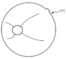
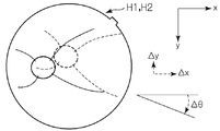
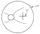
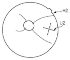
- FIG. 4 shows an example of a positional shift state between the fundus photographed images H1 and H2.
- 4A represents the first fundus photographic image H1
- FIG. 4B represents the second fundus photographic image H2.
- FIG. 4C shows a state in which the first fundus photographic image H1 (solid line) and the second fundus photographic image H2 (broken line) are overlapped in order to show the positional relationship between both fundus photographic images H1 and H2.
- the xy coordinate system shown in FIG. 4C corresponds to the xy coordinate system included in the xyz coordinate system shown in FIG. Further, “ ⁇ ” represents a positional shift amount of the second fundus photographic image H2 with respect to the first fundus photographic image H1. That is, ⁇ x represents the parallel movement amount in the x direction, ⁇ y represents the parallel movement amount in the y direction, and ⁇ represents the rotational movement amount.
- the cross-section position specifying unit 233 is substantially on the fundus oculi Ef depicted in each of the first fundus photographic image H1 and the second fundus photographic image H2 based on the position shift amount calculated by the position shift amount calculation unit 232. Specify the cross-sectional position at the same position.
- the cross-section position designation unit 233 is an example of the “designation unit” of the present invention.
- the positional deviation amount between the two fundus photographic images H1 and H2 is obtained by the positional deviation amount calculation unit 232, the fundus photographic images H1 and H2 can be aligned in the fundus surface direction. This alignment can be performed by relatively moving the two fundus photographic images H1 and H2 so as to cancel out the obtained positional deviation amount. Further, instead of moving the image, association may be performed in consideration of the positional deviation amount between the pixels in the fundus photographic image H1 and the pixels in the fundus photographic image H2. In any case, the position in the fundus photographic image H1 and the position in the fundus photographic image H2 can be associated with each other by taking the positional deviation amount into consideration.
- the amount of positional deviation is obtained as the positional deviation of the image area corresponding to the characteristic part of the fundus oculi Ef. Therefore, this alignment associates the position of the part in the first fundus photographic image H1 with the position of the part in the second fundus photographic image H2 for each part of the fundus oculi Ef.
- the cross-sectional position designating unit 233 sets the cross-sectional position at substantially the same position on the fundus oculi Ef depicted in each of the first fundus photographic image H1 and the second fundus photographic image H2 associated by such alignment. specify.
- the cross-sectional position specified by the cross-section position specifying unit 233 will be described.
- the number of designated cross-sectional positions may be one or plural.
- the subsequent processing is executed for each cross-sectional position.
- Examples of the plurality of cross-sectional positions include a cross-shaped cross-sectional position and a radial cross-sectional position.
- the cross-shaped cross-sectional position is composed of a pair of linear cross-sectional positions that are orthogonal to each other and intersect each other.
- An example of the cross-sectional position of the cross shape is shown in FIG.
- a cross-shaped cross-sectional position U1 shown in FIG. 5A is designated for the first fundus photographic image H1
- a cross-shaped cross-sectional position U2 shown in FIG. 5B is designated for the second fundus photographic image H2.
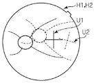
- FIG. 5C shows a first fundus photographic image H1 and a cross-sectional position U1 (solid line), a second fundus photographic image H2 and a cross-sectional position U2 (broken line) in order to show the positional relationship between the two cross-sectional positions U1 and U2.
- Both cross-sectional positions U1 and U2 are designated at substantially the same position on the fundus oculi Ef.
- the cross-shaped cross-sectional positions U1 and U2 have the same form as a scanning line for cross scanning described later.
- the radial cross-sectional position is composed of two or more linear cross-sectional positions arranged radially and intersecting each other (illustration is omitted).
- the two cross-sectional positions are arranged so as to be orthogonal to each other in the radial cross-sectional position, the above-described cross-shaped cross-sectional position is obtained.
- the radial cross-sectional position has the same form as the scanning line of the radiation scan described later.
- the cross-sectional position specified by the cross-section position specifying unit 233 is not limited to the above example.
- the cross-sectional position so as to pass through the site of the fundus oculi Ef having a characteristic shape in the fundus depth direction (z direction).
- a part having this characteristic shape there is a part (uneven part) having irregularities in the fundus depth direction. Examples of such irregularities include the optic nerve head and the macula, and also the affected area with irregularities.
- the cross-sectional position designating unit 233 executes, for example, the following processing.
- the cross-sectional position specifying unit 233 specifies the cross-sectional position so as to pass through the image region.
- the size (length, etc.) of the cross-sectional position may be set in advance, or may be set according to the size of the image area.
- the cross-sectional position specifying part 233 can be configured to specify the image area corresponding to the uneven part. This identification process is the same as the process performed by the positional deviation amount calculation unit 232.
- the cross-section position specifying unit 233 generates a two-dimensional image (integrated image) by integrating the three-dimensional images M1 and M2 in the fundus depth direction.
- pixel values luminance values
- a scan image a depth direction image
- the dot-like image obtained by integrating the A-scan images has a luminance value obtained by adding the luminance value at each z position of the A-scan image in the depth direction (exceeds the maximum gradation value of the luminance value). If so, perform appropriate image processing).
- the accumulated image is described in detail in Japanese Patent Application No. 2005-337628 by the present applicant.
- the accumulated image is an image depicting the surface of the fundus as if it were a fundus photographed image, but high image quality such as a fundus photographed image cannot be obtained.
- the cross-sectional position specifying unit 233 specifies an image region corresponding to a characteristic part of the fundus oculi Ef in the three-dimensional image M1 based on the pixel value of the accumulated image based on the first three-dimensional image M1, and performs first fundus photographing. An image region corresponding to the characteristic part is specified in the image H1. Then, the cross-section position specifying unit 233 performs alignment between these characteristic portions in the same manner as the positional deviation amount calculation unit 232.
- the cross-section position specifying unit 233 analyzes the first three-dimensional image M1 and specifies an image region corresponding to a predetermined uneven portion. Since the first three-dimensional image M1 depicts the three-dimensional form of the fundus oculi Ef, for example, by searching for unevenness in the z direction in the image region corresponding to the fundus surface, the uneven portion can be easily identified. . Subsequently, the cross-sectional position designating unit 233 specifies an image region in the first fundus photographic image H1 corresponding to the image region of the uneven portion based on the above-described alignment result of the characteristic portion, and this image region is determined. Specify the cross-sectional position to pass. The process of designating the cross-sectional position for the second fundus photographic image H2 can be executed in the same manner.
- the process of designating the cross-sectional position for each fundus photographic image H1, H2 based on each three-dimensional image M1, M2 can also be performed without interposing the accumulated image.
- the cross-section position specifying unit 233 first specifies an image region corresponding to a characteristic part of the fundus oculi Ef in each of the first fundus photographic image H1 and the first three-dimensional image M1, and between these image regions. The amount of positional deviation in the xy direction is obtained. Since both images are defined using the x-coordinate and the y-coordinate, this process can be easily executed in the same manner as the positional deviation amount calculation unit 232.
- the cross-section position specifying unit 233 specifies an image region corresponding to a predetermined uneven portion in the first three-dimensional image M1. Further, the cross-section position specifying unit 233 specifies an image area in the first fundus photographic image H1 corresponding to the image area of the uneven portion based on the position shift amount, and cross-sections so as to pass through the image area. Specify the position. The process of designating the cross-sectional position for the second fundus photographic image H2 can be executed in the same manner.
- the image region corresponding to the uneven portion it is also possible to set a cross-sectional position passing through the image region corresponding to an arbitrary portion of the fundus oculi Ef.
- the designated cross-sectional position is used to determine the amount of tilt deviation in the fundus depth direction. Therefore, if the cross-sectional position is specified so that the surface of the fundus oculi Ef or the deep layer of the fundus oculi Ef is clearly depicted in the tomographic image, the relative inclination of the surface or layer can be obtained. That is, on the condition that such a tomographic image is obtained, it is possible to designate a cross-sectional position that passes through an image region corresponding to an arbitrary part of the fundus oculi Ef.
- the image processing unit 230 stores position information (cross-section position information) of a cross-sectional position designated on each fundus photographic image H1, H2.
- This cross-sectional position information is, for example, the coordinate value of the xy coordinate system in each fundus photographed image H1, H2. Since the optical axis (imaging optical axis) of the imaging optical system 30 is aligned with the eye E during fundus imaging, the frame centers of the respective fundus images H1 and H2 substantially coincide with the imaging optical axis. Considering this, it is also possible to store the displacement of the cross-sectional position with respect to the photographing optical axis as cross-sectional position information.
- the image processing unit 230 forms a tomographic image at the cross-sectional position specified by the cross-sectional position specifying unit 233 based on the three-dimensional images M1 and M2. Instead of actually forming the tomographic image, it is also possible to execute the subsequent processing with reference to the pixels at the cross-sectional positions of the three-dimensional images M1 and M2 corresponding to the designated cross-sectional positions.
- the image processing unit 230 first performs alignment between the first fundus image H1 and the first three-dimensional image M1. This process can be performed, for example, through the above-described integrated image, or can be performed by aligning the image region of the characteristic part.
- the image processing unit 230 specifies a position in the first three-dimensional image M1 corresponding to the cross-sectional position designated in the first fundus photographed image H1 based on the result of the above alignment. Then, the image processing unit 230 forms a tomographic image (first tomographic image) along the specific position (having the same form as the cross-sectional position) based on the first three-dimensional image M1. This processing is performed by specifying pixels (such as voxels) positioned along the specific position, and arranging the specified pixels two-dimensionally to form an image representing the form of the fundus oculi Ef in the cross section. . The same applies to the process of forming a tomographic image (second tomographic image) at the cross-sectional position designated in the second fundus photographic image H2.
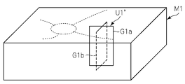
- FIG. 6A shows a cross-shaped cross-sectional position U1 designated in the first fundus photographic image H1.
- FIG. 6B shows a cross-shaped cross-sectional position U1 ′ set on the first three-dimensional image M1 according to the cross-sectional position U1.
- two tomographic images G1a and G1b along the cross-sectional position U1 ′ are shown in FIG. 6B.
- These tomographic images G1a and G1b are examples of the first tomographic image described above.
- the second tomogram is obtained in the same manner.
- the inclination shift amount calculation unit 235 has, for each cross-section position designated by the cross-section position designation unit 233, a surface (target surface) stretched by a direction along the cross-sectional position (cross-sectional direction) and a fundus depth direction (z direction). An inclination shift amount between the first tomographic image and the second tomographic image is calculated based on the first tomographic image and the second tomographic image.
- the tilt deviation amount calculation unit 235 is an example of the “second calculation unit” in the present invention.
- the first cross-sectional position and the second cross-sectional position are designated at substantially the same position on the fundus oculi Ef
- the first tomographic image and the second tomographic image are images on substantially the same cross-section of the fundus oculi Ef. It is. Therefore, it can be said that the inclination shift amount calculation unit 235 compares the state at the first inspection timing and the state at the second inspection timing with respect to the cross section at substantially the same position.
- the cross-sectional position designated by the cross-sectional position designation unit 233 is arranged in a direction along an arbitrary direction on the xy plane.
- the target surfaces in this case are the xz plane and the yz plane.
- the second cross-sectional position is 45 degrees from the x direction toward the y direction.
- the third cross-sectional position is arranged in the 90-degree direction
- the fourth cross-sectional position is arranged in the 135-degree direction.
- the cross-sectional direction is constant at each point on the cross-sectional position, and the surface stretched by the cross-sectional direction and the z direction is a plane.
- the cross-sectional position is not linear, such as a curved line or a polygonal line, the cross-sectional direction changes according to a point on the cross-sectional position, and the obtained surface is not a flat surface.
- the target surface is a two-dimensional region obtained by extending the cross-sectional position in the depth direction. For example, when a circular cross-sectional position is used, a cylindrical target surface whose axis is the z direction is obtained.
- the tilt deviation amount calculation unit 235 specifies an image area (comparison area) in which a predetermined part of the fundus oculi Ef is depicted for each of the first tomographic image and the second tomographic image.
- the predetermined part is desirably a part that is clearly depicted in the tomographic image or a part that is depicted in a characteristic shape in the tomographic image.
- the predetermined portion is a portion whose shape does not substantially change with time. Examples of such a predetermined site include an optic disc, macula, retinal surface, and a predetermined layered tissue of the retina and choroid.
- the comparison region corresponding to the predetermined part is identified by well-known image processing such as analysis of the pixel value of the tomographic image and shape analysis of the image region.
- the inclination shift amount calculation unit 235 compares the comparison area (first comparison area) in the first tomographic image with the comparison area (second comparison area) in the second image area. An inclination is calculated, and this is set as an inclination shift amount between the first tomographic image and the second tomographic image.
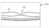
- FIG. 7A shows the first tomogram G1a shown in FIG. 6B.
- the first tomographic image G1a is a tomographic image along a linear cross-sectional position (target cross-sectional position) substantially along the x direction at the cross-shaped cross-sectional position U1 shown in FIG. 5A.
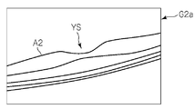
- FIG. 7B shows a second tomographic image G2a along the straight cross-sectional position corresponding to the target cross-sectional position at the cross-sectional position U2 shown in FIG. 5B.
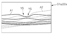
- the first and second tomographic images G1a and G2a depict the macular (corresponding image area) YS of the fundus oculi Ef and the vicinity thereof.
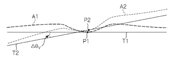
- Symbols A1 and A2 in FIGS. 7A and 7B indicate comparison regions corresponding to the retina surface (the predetermined portion) of the fundus oculi Ef, respectively.
- FIG. 7C shows the tomographic images G1a and G2a superimposed on each other in order to show that the first and second tomographic images G1a and G2a are relatively inclined.
- FIG. 8 is an enlarged view of only the comparison areas A1 and A2 shown in FIG. 7C.
- the tilt shift amount calculation unit 235 calculates the tilt shift amount between the first tomographic image G1a and the second tomographic image G2a by executing the following processing based on the comparison areas A1 and A2. To do.
- the tilt deviation amount calculation unit 235 first identifies the feature position in each of the comparison areas A1 and A2. This feature position may be one point in the comparison area or an area having a spread.
- the image positions P1 and P2 corresponding to the deepest part (fovea) of the macular YS in the comparison areas A1 and A2 are specified as characteristic parts, respectively.
- the inclination shift amount calculation unit 235 obtains a curve that optimally approximates each of the comparison areas A1 and A2.
- this approximate curve an appropriate one such as a spline curve or a Bezier curve is used.
- the inclination shift amount calculation unit 235 analyzes the shape of the approximate curve, for example, by calculating the first-order differential coefficient and the second-order differential coefficient at each point of the approximate curve, so that the feature position (fovea) The image positions P1 and P2 corresponding to are specified.
- the characteristics (position, shape, etc.) of the feature position in the comparison area can be used.
- the concave part (macular) is identified based on the differential coefficient of each point, and this concave The deepest part is specified with reference to the differential coefficient of each point on the part.
- the feature position corresponding to the fovea may be obtained as follows. First, a line segment connecting the edges of the concave portion is obtained. Next, the midpoint of the line segment is obtained. Further, a straight line orthogonal to the line segment and passing through the midpoint is obtained. Then, the intersection of the straight line and the concave part is obtained. This intersection is taken as the target feature position.
- the inclination deviation amount calculation unit 235 determines the direction (or inclination) of the tomographic image based on the feature position.
- the tangent lines T1 and T2 of the comparison areas A1 and A2 at the image positions P1 and P2 corresponding to the fovea are obtained, and the tangent direction is set as the direction of each tomographic image G1a and G2a.
- the approximation curve is used to enable differentiation at each point on the comparison area, but there are cases where this is not the case.
- the direction of the tomographic image can be determined in the same manner as in this processing example as long as differentiation is possible at least at the feature position.
- a differentiable point may be defined as a characteristic part.
- the feature position is a non-differentiable point, for example, a differentiable point separated from the feature position by a predetermined distance (path) along the comparison region is obtained, and in this respect, the same processing as this processing example is obtained. It can be performed.
- the inclination shift amount calculation unit 235 calculates an angle formed by these directions.
- the inclination shift amount calculation unit 235 calculates an angle ⁇ V formed by the tangent line T1 and the tangent line T2. This angle ⁇ V is employed as the amount of tilt deviation between the tomographic images G1a and G2a.
- the tilt deviation amount is a vector amount.
- the tangent line T1 in the first tomographic image G1a is used as a reference (that is, angle 0), and the counterclockwise direction is an angle with respect to the center position (intersection of the tangent line T1 and the tangent line T2) at the time of angle measurement.
- the positive direction In the case shown in FIG. 8, the tangent T2 is displaced in the positive direction by [Delta] [theta] V relative to the tangent T1.
- the angle of the tangent line T1 with respect to the tangent line T2 may be obtained, or the angle of each tangent line T1, T2 with respect to a predetermined reference direction may be obtained. In any case, it is sufficient if the relative inclination shift amount between the tangent lines T1 and T2 can be expressed.
- the inclination shift amount calculation unit 235 performs the above-described processing for each cross-sectional position. Thereby, for each cross-sectional position, an inclination shift amount between the first tomographic image and the second tomographic image along the cross-sectional position is obtained.
- the above-described processing is executed for each of a plurality of cross-sectional positions forming the radial cross-sectional position. Thereby, a plurality of tilt shift amounts corresponding to a plurality of cross-sectional positions forming a radial cross-sectional position are obtained.
- the alignment processing unit 236 uses the first three-dimensional image M1 and the second two-dimensional image M1 based on the positional deviation amount calculated by the positional deviation amount calculation unit 232 and the inclination deviation amount calculated by the inclination deviation amount calculation unit 235. Is aligned with the three-dimensional image M2.
- the alignment processing unit 236 is an example of the “alignment unit” in the present invention.
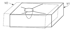
- FIG. 9 shows a positional shift state between the first three-dimensional image M1 and the second three-dimensional image M2.
- FIG. 9C shows the three-dimensional images M1 and M2 superimposed on each other in order to show a positional shift state between the first three-dimensional image M1 shown in FIG. 9A and the second three-dimensional image M2 shown in FIG. 9B. It is what was presented.
- the positional deviation amount calculated by the positional deviation amount calculation unit 232 includes the parallel movement amounts ⁇ x and ⁇ y and the rotational movement amount ⁇ .
- the slope deviation amount calculated by the inclination shift amount calculating unit 235 is [Delta] [theta] V.
- the cross-shaped cross-sectional positions U1 and U2 are formed by a horizontal cross-sectional position and a vertical cross-sectional position, respectively.
- This inclination deviation amount ⁇ V includes an inclination deviation amount ⁇ V 1 corresponding to the horizontal cross-sectional position and an inclination deviation amount ⁇ V 2 corresponding to the vertical cross-sectional position (not shown).
- the positioning process unit 236, the values [Delta] x, [Delta] y, [Delta] [theta], so as to cancel the [Delta] [theta] V, and aligned by relatively moving these 3-dimensional images M1, M2.
- the alignment processing unit 236 translates the second three-dimensional image M2 by ⁇ x in the x direction and ⁇ y in the y direction, and rotates and moves it by ⁇ in the xy plane.
- the alignment processing unit 236 applies the second three-dimensional image M2 to ⁇ in a plane stretched by the direction along the cross-sectional position on the second three-dimensional image M2 and the fundus depth direction (z direction). Rotate and move by V1 .
- the alignment processing unit 236 displays the second 3D image M2 in a plane stretched by the direction along the longitudinal sectional position on the second 3D image M2 and the fundus depth direction (z direction). Rotate and move by ⁇ V 2.
- the alignment processing of the three-dimensional images M1 and M2 is not limited to the above. That is, the value [Delta] x, to counteract [Delta] y, [Delta] [theta], the [Delta] [theta] V, so long as it is capable of moving one or both of the two three-dimensional images M1, M2, it is possible to apply any of the alignment process.
- the image of the fundus oculi Ef depicted in the first three-dimensional image M1 the image of the fundus oculi Ef depicted in the second three-dimensional image M2, and Are relatively parallel and rotated between the three-dimensional images M1 and M2.
- the inclination shift correction unit 237 operates when a radial cross-sectional position is specified by the cross-sectional position specifying unit 233.
- the tilt shift amount calculation unit 235 calculates the tilt shift amount for each cross-sectional position forming a radial cross-sectional position.
- the inclination deviation correction unit 237 first selects the maximum value of the inclination deviation amounts corresponding to these cross-sectional positions. This process is executed by selecting an inclination value (maximum inclination deviation amount) having the maximum absolute value from among the inclination deviation amounts (a vector amount, that is, expressed by an angle having a direction).
- the inclination deviation correction unit 237 is arranged in a plane stretched by the direction along the cross-sectional position corresponding to the maximum inclination deviation amount and the fundus depth direction (z direction) so as to cancel the selected maximum inclination deviation amount.
- the deviation of the inclination between the first and second three-dimensional images M1 and M2 is corrected.
- the inclination deviation correction unit 237 relatively rotates the first and second three-dimensional images M1 and M2 on the xz plane so as to cancel the maximum inclination deviation amount ⁇ Vmax .
- the inclination shift correction unit 237 rotates the second three-dimensional image M2 by ⁇ Vmax on the xy plane. Thereby, the inclination (maximum inclination) in the plane direction of the image of the fundus oculi Ef depicted in each of the first and second three-dimensional images M1 and M2 is corrected.
- Such an inclination shift correcting unit 237 is an example of the “correcting unit” of the present invention.
- the image analysis unit 238 analyzes the first three-dimensional image M1 and calculates a first value of a predetermined physical quantity. Similarly, the image analysis unit 238 analyzes the second three-dimensional image M2 and calculates a second value of a predetermined physical quantity. Note that the three-dimensional images M1 and M2 analyzed by the image analysis unit 238 have not been subjected to the above-described alignment process or tilt shift correction process. Further, “analyze the three-dimensional images M1 and M2” includes a case where an OCT image (tomographic image or the like) based on the three-dimensional images M1 and M2 is analyzed. The image analysis unit 238 is an example of the “analysis unit” in the present invention.
- the “predetermined physical quantity” to be calculated is an arbitrary test result (obtained as a numerical value) referred to in diagnosis of fundus oculi disease. Specific examples include the size of the lesion (radius, diameter, area, volume, etc.), the depth of the lesion from the retina surface, the size of the optic disc (cup size, disc size, rim size, etc.), retinal pigment epithelium (Retinal Pigment) Epithelium (RPE) spacing, retinal thickness, etc.
- the images used for the processing of the image analysis unit 238 include the three-dimensional images M1 and M2 of the fundus oculi Ef and the tomographic images obtained from these three-dimensional images M1 and M2.
- the process of forming a tomographic image from the three-dimensional images M1 and M2 is executed in the same manner as described above.
- the process of forming a tomographic image at an arbitrary cross-sectional position based on a three-dimensional image is called multi-planar reconstruction (MPR).
- MPR multi-planar reconstruction
- the fundus photographic images H1 and H2 may be analyzed to calculate a predetermined physical quantity.
- a tomographic image J1 shown in FIG. 11A is obtained by designating a linear cross-sectional position along the x direction through the image region OP corresponding to the optic disc for the first three-dimensional image M1.
- the tomographic image J2 shown in FIG. 11B is obtained by designating the same cross-sectional position for the second three-dimensional image M2. That is, the tomographic images J1 and J2 are two-dimensional images on the xz plane.
- Reference numerals B1 and B2 denote retinal surfaces (corresponding image areas).
- the image analysis unit 238 analyzes the tomographic image J1 and calculates the RPE interval d1. More specifically, the image analysis unit 238 first analyzes the pixel values of the pixels constituting the tomographic image J1, and specifies the image region OP1 corresponding to the optic nerve head and the image region C1 corresponding to RPE. .
- the image region OP1 is specified by, for example, specifying the image region B1 corresponding to the retina surface and analyzing the shape of the image region B1 to specify the concave image region corresponding to the optic disc. it can.
- the image region C1 corresponding to the RPE is specified by, for example, specifying image regions of various layered tissues (boundaries) of the fundus oculi Ef depicted in the tomographic image J1, and determining the luminance of these image regions and the retinal surface B1. This can be done by selecting the equivalent of RPE based on depth. Since the RPE is positioned so as to surround the optic disc, the tomographic image J1 specifies the image region C1 on both the + x side and the ⁇ x side with respect to the image region OP1 corresponding to the optic disc. .
- the image analysis unit 238 specifies a pixel (closest pixel) located closest to the image region OP1 among pixels in the image region C1 corresponding to the RPE located on the + x side with respect to the image region OP1. .
- a distance to each pixel in the image area OP1 (for example, Euclidean distance in the xz coordinate system) is calculated, and the shortest of these distances is selected.
- the shortest of the shortest pixel distances in the image area C1 obtained in this way is selected.
- the pixel corresponding to the selected shortest distance becomes the target pixel.
- the radius of a circle centered on the pixel is gradually enlarged until it touches (or intersects) the image area OP1.
- the radius at this time is the distance between the pixel and the image area OP1.
- the pixel with the shortest distance is the target pixel.
- the closest pixel is similarly specified for the image region C1 corresponding to the RPE located on the ⁇ x side with respect to the image region OP1.
- the image analysis unit 238 calculates a distance d1 between the nearest pixel located on the + x side and the nearest pixel located on the ⁇ x side with respect to the image region OP1.
- the distance d1 may be a Euclidean distance in the xz coordinate system, or may be a distance along the x direction (that is, an x component of the Euclidean distance). This distance d1 is the RPE interval based on the tomographic image J1.
- the tomographic image J2 shown in FIG. 11B is relatively inclined with respect to the tomographic image J1 shown in FIG. 11A. If processing similar to that of the tomographic image J1 is executed as in the prior art, this inclination is not reflected in the calculation of the RPE interval, so the analysis results of the tomographic images J1 and J2 acquired under different conditions are compared. Large errors may occur. For example, in the case shown in FIG. 11, when distances along the x direction are compared, for example, the distance d1 shown in FIG. 11A and the distance d2 ′ shown in FIG. 11B are obtained as RPE intervals, respectively. Comparison accuracy is greatly reduced.
- the tomographic images J1 and J2 are both inclined with respect to the true direction due to the movement of the eye E, and it is extremely difficult to obtain the true value of the RPE interval.
- the comparative observation since it is necessary to compare both analysis results under (substantially) the same conditions, it is possible to improve accuracy by considering the relative inclination.
- the image analysis unit 238 performs the following processing to reflect the inclination in the analysis result in order to improve the accuracy of comparative observation.
- the image analysis unit 238 specifies an image region OP2 corresponding to the optic disc and an image region C2 corresponding to RPE in the same manner as the processing related to the tomographic image J1. Further, the image analysis unit 238 specifies the closest pixel in the image region C2 corresponding to the RPE located on the + x side and the ⁇ x side with respect to the image region OP2.
- the image analysis unit 238 calculates the measurement direction of the distance d1 when the RPE interval is obtained for the tomographic image J1 (that is, the direction of the double-sided arrow indicating the RPE interval in FIG. 11A) by the inclination deviation amount calculation unit 235. Is inclined by the amount of inclination deviation ⁇ V. Then, a distance d2 between the nearest pixel on the + x side and the nearest pixel on the -x side is calculated along this inclination direction. This distance d2 is the RPE interval based on the tomographic image J2. Thereby, RPE intervals d1 and d2 measured in substantially the same direction with respect to the tomographic images J1 and J2 are obtained, and the RPE intervals can be compared with high accuracy.
- the image processing unit 230 that functions as described above includes, for example, the aforementioned microprocessor, RAM, ROM, hard disk drive, circuit board, and the like.
- a storage device such as a hard disk drive, a computer program for causing the microprocessor to execute the above functions is stored in advance.
- the display unit 240 includes the display device of the arithmetic control unit 200 described above.
- the operation unit 250 includes the operation device of the arithmetic control unit 200 described above.
- the operation unit 250 may include various buttons and keys provided on the housing of the fundus oculi observation device 1 or outside.
- the operation unit 250 may include a joystick, an operation panel, or the like provided on the housing.
- the display unit 240 may include various display devices such as a touch panel monitor provided on the housing of the fundus camera unit 2.
- the display unit 240 and the operation unit 250 need not be configured as individual devices.
- a device in which a display function and an operation function are integrated, such as a touch panel monitor, can be used.
- Examples of the scanning mode of the signal light LS by the fundus oculi observation device 1 include a horizontal scan, a vertical scan, a cross scan, a radiation scan, a circle scan, a concentric scan, and a spiral (vortex) scan. These scanning modes are selectively used as appropriate in consideration of the observation site of the fundus, the analysis target (such as retinal thickness), the time required for scanning, the precision of scanning, and the like.
- the horizontal scan is to scan the signal light LS in the horizontal direction (x direction).
- the horizontal scan also includes an aspect in which the signal light LS is scanned along a plurality of horizontal scanning lines arranged in the vertical direction (y direction). In this aspect, it is possible to arbitrarily set the scanning line interval. Further, the above-described three-dimensional image can be formed by sufficiently narrowing the interval between adjacent scanning lines (three-dimensional scanning). The same applies to the vertical scan.
- the cross scan scans the signal light LS along a cross-shaped trajectory composed of two linear trajectories (straight trajectories) orthogonal to each other.
- the signal light LS is scanned along a radial trajectory composed of a plurality of linear trajectories arranged at a predetermined angle.
- the cross scan is an example of a radiation scan.
- the circle scan scans the signal light LS along a circular locus.
- the signal light LS is scanned along a plurality of circular trajectories arranged concentrically around a predetermined center position.
- a circle scan is an example of a concentric scan.
- the signal light LS is scanned along a spiral (spiral) locus while the radius of rotation is gradually reduced (or increased).
- the galvanometer mirrors 43 and 44 are configured to scan the signal light LS in directions orthogonal to each other, the signal light LS can be scanned independently in the x direction and the y direction, respectively. Furthermore, by simultaneously controlling the directions of the galvanometer mirrors 43 and 44, it is possible to scan the signal light LS along an arbitrary locus on the xy plane. Thereby, various scanning modes as described above can be realized.
- a tomographic image in the fundus depth direction (z direction) along the scanning line (scanning locus) can be formed.
- the above-described three-dimensional image can be formed.
- the region on the fundus oculi Ef to be scanned with the signal light LS as described above, that is, the region on the fundus oculi Ef to be subjected to OCT measurement is referred to as a scanning region.
- the scanning area in the three-dimensional scan is a rectangular area in which a plurality of horizontal scans are arranged.
- the scanning area in the concentric scan is a disk-shaped area surrounded by the locus of the circular scan with the maximum diameter.
- the scanning area in the radial scan is a disk-shaped (or polygonal) area connecting both end positions of each scan line.
- the fundus oculi observation device 1 includes the first fundus photographic image H1 and the first three-dimensional image M1 acquired at the first examination timing, and the second fundus photographic image H2 and the first fundus photographic image H2 obtained at the second examination timing. 2 three-dimensional images M2 are stored.
- the fundus oculi observing device 1 is based on the first fundus photographic image H1 and the second fundus photographic image H2, and the first fundus photographic image H1 and the second fundus photographic image H2 in the fundus surface direction (xy direction). Displacement amounts ⁇ x, ⁇ y, and ⁇ between are calculated.
- the fundus oculi observation device 1 designates a cross-sectional position at substantially the same position on the fundus oculi Ef depicted in each fundus oculi image H1, H2 based on the calculated positional deviation amounts ⁇ x, ⁇ y, ⁇ .
- the fundus oculi observation device 1 forms a first tomographic image at the cross-sectional position designated in the first fundus photographic image H1 based on the first three-dimensional image M1, and also the second three-dimensional image. Based on M2, a second tomographic image is formed at the cross-sectional position designated in the second fundus photographic image H2.
- the subsequent processing is executed with reference to the pixels at the cross-sectional positions of the three-dimensional images M1 and M2 corresponding to the designated cross-sectional positions. May be.
- the fundus oculi observation device 1 uses the first tomographic image and the second tomographic image to generate a first tomographic image on a plane stretched in the direction along the designated cross-sectional position and the fundus depth direction (z direction).
- An inclination shift amount ⁇ V between the image and the second tomographic image is calculated.
- the positional deviation amounts ⁇ x, ⁇ y, ⁇ and the inclination deviation amount ⁇ V interposed between images (particularly the three-dimensional images M1, M2) to be compared in the comparative observation are obtained.
- the fundus oculi observation device 1 can designate a plurality of cross-sectional positions for the respective fundus oculi images H1 and H2.
- the fundus oculi observation device 1 forms a first tomographic image and a second tomographic image for each of a plurality of designated sectional positions, and the first tomographic image and the second tomographic image at each sectional position.
- the amount of tilt deviation in the surface stretched between the direction along the cross-sectional position and the fundus depth direction is calculated. Thereby, a plurality of pairs of tomographic images corresponding to a plurality of cross-sectional positions are obtained.
- the fundus oculi observation device 1 can designate a cross-shaped cross-sectional position, that is, a pair of linear cross-sectional positions intersecting at right angles to each other.
- the fundus oculi observation device 1 calculates a tilt shift amount by forming a first tomographic image and a second tomographic image for each designated cross-sectional position. Thereby, the amount of inclination shift in each of a pair of planes orthogonal to each other is obtained.
- the tilt shift is calculated as a vector sum of the pair of tilt shift amounts.
- a radial cross-sectional position that is, two or more linear cross-sectional positions arranged radially and intersecting each other.
- the fundus oculi observation device 1 calculates a tilt shift amount by forming a first tomographic image and a second tomographic image for each designated cross-sectional position. Thereby, the same number of inclination deviation amounts as the number of cross-sectional positions (two or more) can be obtained. Further, the fundus oculi observation device 1 selects the maximum value (maximum inclination deviation amount) of these two or more inclination deviation amounts.
- the fundus oculi observation device 1 has the first three-dimensional image M1 on the plane stretched by the direction along the cross-sectional position corresponding to the maximum tilt shift amount and the fundus depth direction so as to cancel the maximum tilt shift amount.
- the inclination deviation between the second three-dimensional image M2 is corrected.
- the inclination deviation can be corrected in the direction with the largest inclination, so that it is possible to correct the inclination deviation in the direction that has the greatest influence on the comparative observation while saving the resources of the arithmetic control unit 200. is there.
- the cross-sectional position may be specified manually.
- the first and second fundus photographed images H1 and H2 can be displayed on the display unit 240, and the operation unit 250 can be operated to specify the cross-sectional position on these display images.
- one fundus photographed image for example, the first fundus photographed image H1
- the cross-sectional position is manually designated
- the other fundus photographed image for example, the second fundus photographed image H2 is manually selected. It is also possible to configure such that a position substantially the same as the designated cross-sectional position is automatically designated.
- the designation of the cross-sectional position in the fundus photographic images H1 and H2 may be performed automatically, only a part may be performed automatically, or all may be performed manually. .
- the doctor can specify the desired cross-sectional position in both fundus photographic images H1 and H2, so even if the target region is difficult to extract by image processing, the doctor's knowledge and experience can be obtained.
- the cross-sectional position can be specified by taking advantage of it. Which of these methods is adopted is arbitrary. It is also possible to configure such that these methods can be selectively used.
- the fundus oculi observation device 1 the calculated position deviation amount [Delta] x, [Delta] y, so as to cancel the [Delta] [theta] and inclination shift amount [Delta] [theta] V, a position between the first three-dimensional image M1 M2 second three-dimensional image It is possible to combine. As a result, when the three-dimensional images M1 and M2 are visually compared, the common points and differences between the three-dimensional images M1 and M2 can be easily grasped, and thus the accuracy of comparative observation can be improved. Is possible.
- the fundus oculi observation device 1 the calculated position deviation amount [Delta] x, [Delta] y, based on one or both of [Delta] [theta] and the slope deviation amount [Delta] [theta] V, the first analysis of a given physical quantity based on the first three-dimensional image M1
- a result (first value) and a second analysis result (second value) of a predetermined physical quantity based on the second three-dimensional image M2 can be calculated.
- these deviation amounts are not taken into consideration, and therefore there is a possibility that the comparison accuracy of the analysis result may be lowered according to the difference in conditions between the first inspection timing and the second inspection timing. It was.
- the analysis result is obtained in consideration of the above-described deviation amount due to the difference in the conditions, it is possible to compare the analysis result with higher accuracy than before. .
- the positional deviation amounts ⁇ x, ⁇ y, ⁇ in the fundus surface direction (xy direction) and the inclining deviation amount ⁇ V in the plane including the fundus depth direction (z direction) are obtained.
- a positional shift amount in the z direction may be obtained.
- a method for obtaining the amount of positional deviation in the z direction for example, there is the following. First, z coordinate values in a frame of a predetermined part of the fundus oculi Ef in each of the first tomographic image and the second tomographic image are obtained. Then, a deviation of these z coordinate values (that is, a positional deviation amount in the z direction) is obtained.
- the predetermined part of the fundus oculi Ef includes the retina surface, the layered tissue of the fundus oculi Ef, and the like. Note that three-dimensional images may be compared instead of comparing tomographic images.
- the amount of positional deviation and the amount of inclination deviation are expressed using the xyz coordinate system, and the image alignment and analysis processing are performed. However, these processes are performed using other coordinate systems. You may make it perform.
- the central position (papillary center) OPa of the optic disc (corresponding image area) OP and the central position (fovea of the macula) YS (corresponding image area) , Macular center) YSa This process can be executed using a conventional fundus image analysis technique.
- a two-dimensional polar coordinate system is defined in which the nipple center OPa is the origin and the direction connecting the nipple center OPa and the fovea YSa is the reference direction S.
- the unit of the distance from the origin OPa can be set, for example, based on the distance between the nipple center OPa and the fovea YSa.
- an arbitrary position P in the fundus photographic image H1 can be expressed by coordinate values (r, ⁇ ).
- r is the distance between the origin OPa and the position P.
- ⁇ is an angle formed by a line segment connecting the origin OPa and the position P with respect to the reference direction S.
- the direction of turning counterclockwise from the origin OPa when viewing the fovea YSa is defined as the positive direction of the angle.
- This two-dimensional polar coordinate system can be used instead of the above xy coordinate system.
- the fundus photographed image is described as an image photographed by a fundus camera or the like, but the fundus photographed image is not limited to this.
- an arbitrary image depicting a two-dimensional form of the fundus surface such as an image obtained by photographing the fundus (for example, the above-described integrated image), can be used as a fundus image.
- the position of the reference mirror 114 is changed to change the optical path length difference between the optical path of the signal light LS and the optical path of the reference light LR, but the method of changing the optical path length difference is limited to this. Is not to be done.
- the optical path length difference can be changed by moving the fundus camera unit 2 or the OCT unit 100 with respect to the eye E to change the optical path length of the signal light LS. It is also effective to change the optical path length difference by moving the measurement object in the depth direction (z direction), particularly when the measurement object is not a living body part.
- the computer program in the above embodiment can be stored in any recording medium readable by a computer.
- this recording medium for example, an optical disk, a magneto-optical disk (CD-ROM / DVD-RAM / DVD-ROM / MO, etc.), a magnetic storage medium (hard disk / floppy (registered trademark) disk / ZIP, etc.), etc. are used. Is possible. It can also be stored in a storage device such as a hard disk drive or memory.
Landscapes
- Health & Medical Sciences (AREA)
- Life Sciences & Earth Sciences (AREA)
- Biomedical Technology (AREA)
- Heart & Thoracic Surgery (AREA)
- Radiology & Medical Imaging (AREA)
- Biophysics (AREA)
- Ophthalmology & Optometry (AREA)
- Engineering & Computer Science (AREA)
- Nuclear Medicine, Radiotherapy & Molecular Imaging (AREA)
- Physics & Mathematics (AREA)
- Medical Informatics (AREA)
- Molecular Biology (AREA)
- Surgery (AREA)
- Animal Behavior & Ethology (AREA)
- General Health & Medical Sciences (AREA)
- Public Health (AREA)
- Veterinary Medicine (AREA)
- Eye Examination Apparatus (AREA)
Abstract
眼底の比較観察を高い確度で行う。位置ズレ量算出部232は、眼底撮影像H1、H2に基づき、眼底表面方向における眼底撮影像H1、H2の間の位置ズレ量を算出する。断面位置指定部233は、位置ズレ量に基づき、各眼底撮影像H1、H2に描写された眼底Ef上の略同一位置に断面位置を指定する。傾きズレ量算出部235は、第1の眼底撮影像H1に指定された断面位置に対応する第1の3次元画像M1の断面位置における第1の断層像と、第2の眼底撮影像H2に指定された断面位置に対応する第2の3次元画像M2の断面位置における第2の断層像とに基づいて、指定された断面位置に沿う方向と眼底深度方向とにより張られる面における、第1の断層像と第2の断層像との間の傾きズレ量を算出する。それにより、第1及び第2の3次元画像M1、M2の間の位置ズレ量と傾きズレ量が得られる。
Description
この発明は、眼底を撮影して得られた眼底撮影像と、光コヒーレンストモグラフィ(Optical Coherence Tomography:OCT)を用いて形成された眼底の3次元画像とを処理する眼底画像処理装置、並びに、眼底撮影像及び/又は眼底の3次元画像を形成可能な眼底観察装置に関する。
近年、レーザ光源等からの光ビームを用いて被測定物体の表面形態や内部形態を表す画像を形成するOCTが注目を集めている。OCTは、X線CTのような人体に対する侵襲性を持たないことから、特に医療分野や生物学分野における応用の展開が期待されている。たとえば眼科分野においては、眼底や角膜等の画像を形成する装置が実用化段階に入っている。
特許文献1にはOCTを適用した装置が開示されている。この装置は、測定腕が回転式転向鏡(ガルバノミラー)により物体を走査し、参照腕に参照ミラーが設置されており、その出口に計測腕及び参照腕からの光束の干渉光の強度を分光器で分析する干渉器が設けられている。更に、参照腕は、参照光光束位相を不連続な値で段階的に変えるように構成されている。
特許文献1の装置は、いわゆる「フーリエドメインOCT(Fourier Domain OCT)」の手法を用いるものである。すなわち、被測定物体に対して低コヒーレンス光のビームを照射し、その反射光と参照光とを重ね合わせて干渉光を生成し、この干渉光のスペクトル強度分布を取得してフーリエ変換を施すことにより被測定物体の深度方向(z方向)の形態を画像化するものである。なお、このタイプの手法は、特にスペクトラルドメイン(Spectral Domain)とも呼ばれる。
更に、特許文献1に記載の装置は、光ビーム(信号光)を走査するガルバノミラーを備え、それにより被測定物体の所望の測定対象領域の画像を形成するようになっている。この装置においては、z方向に直交する1方向(x方向)にのみ光ビームを走査するように構成されているので、この装置により形成される画像は、光ビームの走査方向(x方向)に沿った深度方向(z方向)の2次元断層像となる。
特許文献2には、信号光を水平方向(x方向)及び垂直方向(y方向)に走査(スキャン)することにより水平方向の2次元断層像を複数形成し、これら複数の断層像に基づいて測定範囲の3次元の断層情報を取得して画像化する技術が開示されている。この3次元画像化としては、たとえば、複数の断層像を垂直方向に並べて表示させる方法や(スタックデータなどと呼ばれる)、複数の断層像にレンダリング処理を施して3次元画像を形成する方法などが考えられる。
特許文献3、4には、他のタイプのOCT装置が開示されている。特許文献3には、被測定物体に照射される光の波長を走査し、各波長の光の反射光と参照光とを重ね合わせて得られる干渉光に基づいてスペクトル強度分布を取得し、それに対してフーリエ変換を施すことにより被測定物体の形態を画像化するOCT装置が記載されている。このようなOCT装置は、スウェプトソース(Swept Source)タイプなどと呼ばれる。スウェプトソースタイプはフーリエドメインタイプの一種である。
また、特許文献4には、所定のビーム径を有する光を被測定物体に照射し、その反射光と参照光とを重ね合わせて得られる干渉光の成分を解析することにより、光の進行方向に直交する断面における被測定物体の画像を形成するOCT装置が記載されている。このようなOCT装置は、フルフィールド(full-field)タイプ、或いはインファス(en-face)タイプなどと呼ばれる。
特許文献5には、OCTを眼科分野に適用した構成が開示されている。なお、OCTが応用される以前から、被検眼を観察するための装置として眼底カメラやスリットランプなどが使用されている(たとえば特許文献6、特許文献7を参照)。眼底カメラは被検眼に照明光を照射し、その眼底反射光を受光することで眼底を撮影する装置である。スリットランプは、スリット光を用いて角膜の光切片を切り取ることにより角膜の断面の画像を取得する装置である。
OCTを用いた装置は、高精細の画像を取得できる点、更には断層像や3次元画像を取得できる点などにおいて、眼底カメラ等に対して優位性を持つ。
このように、OCTを用いた装置は被検眼の様々な部位の観察に適用可能であり、また高精細な画像を取得できることから、様々な眼科疾患の診断への応用がなされてきている。
各種医療分野では、たとえば経過観察や術前術後観察のように、異なるタイミングで取得された画像を比較して注目部位(患部、特徴部位等)の状態の経時的な変化を把握する診断手法が取られている(「比較観察」と呼ぶことにする)。眼科分野では、たとえば緑内障や黄斑疾患の診断において比較観察が実施される。その際、画像に描写された注目部位の状態の比較だけでなく、注目部位に関する物理量の定量的な比較を行うことがある。比較対象となる物理量の例として、患部のサイズ(半径、直径、面積、体積等)や、視神経乳頭のカップサイズ、ディスクサイズ、リムサイズなどがある。
このような物理量の定量的な比較を行う際には当然に、比較対象となる物理量をできるだけ正確に求めることが重要である。また、比較の確度を担保するためには、物理量を算出する元になる画像をできるだけ同じ条件で取得する必要がある。
しかしながら、眼科分野におけるOCT計測では、眼球の回転、固視位置のズレ、アライメントのズレなどによって、画像を取得する度にどうしても条件が異なってしまう。その結果、物理量の比較の確度が低下し、また、画像自体を比較する作業を難しくしていた。
この発明は、以上のような問題を解決するためになされたもので、その目的は、眼底の比較観察を高い確度で行うことが可能な眼底画像処理装置及び眼底観察装置を提供することにある。
上記目的を達成するために、請求項1に記載の発明は、第1の検査タイミングで取得された被検眼の第1の眼底撮影像及び前記被検眼の眼底の第1の3次元画像と、前記第1の検査タイミングと異なる第2の検査タイミングで取得された前記被検眼の第2の眼底撮影像及び前記眼底の第2の3次元画像とを予め記憶する記憶手段と、前記第1の眼底撮影像及び前記第2の眼底撮影像に基づいて、眼底表面方向における前記第1の眼底撮影像と前記第2の眼底撮影像との間の位置ズレ量を算出する第1の算出手段と、前記算出された位置ズレ量に基づいて、前記第1の眼底撮影像及び前記第2の眼底撮影像のそれぞれに描写された前記眼底上の略同一位置に断面位置を指定する指定手段と、前記第1の眼底撮影像に指定された断面位置に対応する前記第1の3次元画像の断面位置における第1の断層像と、前記第2の眼底撮影像に指定された断面位置に対応する前記第2の3次元画像の断面位置における第2の断層像とに基づいて、前記指定された断面位置に沿う方向と眼底深度方向とにより張られる面における前記第1の断層像と前記第2の断層像との間の傾きズレ量を算出する第2の算出手段と、を備えることを特徴とする。
また、請求項2に記載の発明は、請求項1に記載の眼底画像処理装置であって、前記指定手段は、複数の前記断面位置を指定し、前記第2の算出手段は、前記複数の断面位置のそれぞれに対応する前記第1及び第2の3次元画像の断面位置について、当該断面位置における前記第1の断層像及び前記第2の断層像に基づいて、前記指定された断面位置に沿う方向と前記眼底深度方向とにより張られる面における前記傾きズレ量を算出する、ことを特徴とする。
また、請求項3に記載の発明は、請求項2に記載の眼底画像処理装置であって、前記指定手段は、前記複数の断面位置として、互いに直交して交差する一対の直線状の断面位置を指定し、前記第2の算出手段は、前記一対の断面位置のそれぞれに対応する前記第1及び第2の3次元画像の断面位置について前記傾きズレ量を算出することにより、互いに直交する一対の平面のそれぞれにおける傾きズレ量を求める、ことを特徴とする。
また、請求項4に記載の発明は、請求項2に記載の眼底画像処理装置であって、前記指定手段は、前記複数の断面位置として、放射状に配置されて互いに交差する2つ以上の直線状の断面位置を指定し、前記第2の算出手段は、前記2つ以上の断面位置のそれぞれに対応する前記第1及び第2の3次元画像の断面位置について前記傾きズレ量を算出し、前記第2の算出手段により算出された前記2つ以上の断面位置に対応する前記傾きズレ量のうちの最大値を選択し、前記選択された傾きズレ量を打ち消すように、当該傾きズレ量に対応する断面位置に沿う方向と前記眼底深度方向とにより張られる平面における前記第1の3次元画像と前記第2の3次元画像との間の傾きのズレを補正する補正手段を更に備える、ことを特徴とする。
また、請求項5に記載の発明は、請求項1~請求項3のいずれか一項に記載の眼底画像処理装置であって、前記第1の算出手段により算出された前記位置ズレ量と前記第2の算出手段により算出された前記傾きズレ量とを打ち消すように、前記第1の3次元画像と前記第2の3次元画像との間の位置合わせを行う位置合わせ手段を更に備える、ことを特徴とする。
また、請求項6に記載の発明は、請求項1~請求項3のいずれか一項に記載の眼底画像処理装置であって、第1の算出手段により算出された前記位置ズレ量及び/又は前記第2の算出手段により算出された前記傾きズレ量に基づいて、前記第1の3次元画像を解析して所定の物理量の第1の値を算出し、かつ、前記第2の3次元画像を解析して前記所定の物理量の第2の値を算出する解析手段を更に備える、ことを特徴とする。
また、請求項7に記載の発明は、請求項1に記載の眼底画像処理装置であって、前記第1の算出手段は、前記位置ズレ量として、前記眼底表面方向における平行移動量と回転移動量とを算出する、ことを特徴とする。
また、請求項8に記載の発明は、被検眼の眼底を撮影する撮影手段と、低コヒーレンス光を信号光と参照光とに分割し、前記眼底を経由した前記信号光と参照光路を経由した参照光とを重畳させて干渉光を生成して検出する光学系と、前記干渉光の検出結果に基づいて前記眼底の3次元画像を形成する画像形成手段と、第1の検査タイミングで前記撮影手段により撮影された前記被検眼の第1の眼底撮影像及び前記画像形成手段により形成された前記眼底の第1の3次元画像と、前記第1の検査タイミングと異なる第2の検査タイミングで前記撮影された前記被検眼の第2の眼底撮影像及び前記形成された前記眼底の第2の3次元画像とを記憶する記憶手段と、前記第1の眼底撮影像及び前記第2の眼底撮影像に基づいて、眼底表面方向における前記第1の眼底撮影像と前記第2の眼底撮影像との間の位置ズレ量を算出する第1の算出手段と、前記算出された位置ズレ量に基づいて、前記第1の眼底撮影像及び前記第2の眼底撮影像のそれぞれに描写された前記眼底上の略同一位置に断面位置を指定する指定手段と、前記第1の眼底撮影像に指定された断面位置に対応する前記第1の3次元画像の断面位置における第1の断層像と、前記第2の眼底撮影像に指定された断面位置に対応する前記第2の3次元画像の断面位置における第2の断層像とに基づいて、前記指定された断面位置に沿う方向と眼底深度方向とにより張られる面における前記第1の断層像と前記第2の断層像との間の傾きズレ量を算出する第2の算出手段と、を備えることを特徴とする眼底観察装置である。
また、請求項9に記載の発明は、低コヒーレンス光を信号光と参照光とに分割し、被検眼の眼底を経由した前記信号光と参照光路を経由した参照光とを重畳させて干渉光を生成して検出する光学系と、前記干渉光の検出結果に基づいて前記眼底の3次元画像を形成する画像形成手段と、第1の検査タイミングで取得された前記被検眼の第1の眼底撮影像と、前記第1の検査タイミングと異なる第2の検査タイミングで取得された前記被検眼の第2の眼底撮影像とを予め記憶するとともに、前記第1の検査タイミングで前記画像形成手段により形成された前記眼底の第1の3次元画像と、前記第2の検査タイミングで前記形成された前記眼底の第2の3次元画像とを記憶する記憶手段と、前記第1の眼底撮影像及び前記第2の眼底撮影像に基づいて、眼底表面方向における前記第1の眼底撮影像と前記第2の眼底撮影像との間の位置ズレ量を算出する第1の算出手段と、前記算出された位置ズレ量に基づいて、前記第1の眼底撮影像及び前記第2の眼底撮影像のそれぞれに描写された前記眼底上の略同一位置に断面位置を指定する指定手段と、前記第1の眼底撮影像に指定された断面位置に対応する前記第1の3次元画像の断面位置における第1の断層像と、前記第2の眼底撮影像に指定された断面位置に対応する前記第2の3次元画像の断面位置における第2の断層像とに基づいて、前記指定された断面位置に沿う方向と眼底深度方向とにより張られる面における前記第1の断層像と前記第2の断層像との間の傾きズレ量を算出する第2の算出手段と、を備えることを特徴とする眼底観察装置である。
また、請求項10に記載の発明は、被検眼の眼底を撮影する撮影手段と、第1の検査タイミングで取得された前記眼底の第1の3次元画像と、前記第1の検査タイミングと異なる第2の検査タイミングで取得された前記眼底の第2の3次元画像とを予め記憶するとともに、前記第1の検査タイミングで前記撮影手段により撮影された前記被検眼の第1の眼底撮影像と、前記第2の検査タイミングで前記撮影された前記被検眼の第2の眼底撮影像とを記憶する記憶手段と、前記第1の眼底撮影像及び前記第2の眼底撮影像に基づいて、眼底表面方向における前記第1の眼底撮影像と前記第2の眼底撮影像との間の位置ズレ量を算出する第1の算出手段と、前記算出された位置ズレ量に基づいて、前記第1の眼底撮影像及び前記第2の眼底撮影像のそれぞれに描写された前記眼底上の略同一位置に断面位置を指定する指定手段と、前記第1の眼底撮影像に指定された断面位置に対応する前記第1の3次元画像の断面位置における第1の断層像と、前記第2の眼底撮影像に指定された断面位置に対応する前記第2の3次元画像の断面位置における第2の断層像とに基づいて、前記指定された断面位置に沿う方向と眼底深度方向とにより張られる面における前記第1の断層像と前記第2の断層像との間の傾きズレ量を算出する第2の算出手段と、を備えることを特徴とする眼底観察装置である。
また、請求項2に記載の発明は、請求項1に記載の眼底画像処理装置であって、前記指定手段は、複数の前記断面位置を指定し、前記第2の算出手段は、前記複数の断面位置のそれぞれに対応する前記第1及び第2の3次元画像の断面位置について、当該断面位置における前記第1の断層像及び前記第2の断層像に基づいて、前記指定された断面位置に沿う方向と前記眼底深度方向とにより張られる面における前記傾きズレ量を算出する、ことを特徴とする。
また、請求項3に記載の発明は、請求項2に記載の眼底画像処理装置であって、前記指定手段は、前記複数の断面位置として、互いに直交して交差する一対の直線状の断面位置を指定し、前記第2の算出手段は、前記一対の断面位置のそれぞれに対応する前記第1及び第2の3次元画像の断面位置について前記傾きズレ量を算出することにより、互いに直交する一対の平面のそれぞれにおける傾きズレ量を求める、ことを特徴とする。
また、請求項4に記載の発明は、請求項2に記載の眼底画像処理装置であって、前記指定手段は、前記複数の断面位置として、放射状に配置されて互いに交差する2つ以上の直線状の断面位置を指定し、前記第2の算出手段は、前記2つ以上の断面位置のそれぞれに対応する前記第1及び第2の3次元画像の断面位置について前記傾きズレ量を算出し、前記第2の算出手段により算出された前記2つ以上の断面位置に対応する前記傾きズレ量のうちの最大値を選択し、前記選択された傾きズレ量を打ち消すように、当該傾きズレ量に対応する断面位置に沿う方向と前記眼底深度方向とにより張られる平面における前記第1の3次元画像と前記第2の3次元画像との間の傾きのズレを補正する補正手段を更に備える、ことを特徴とする。
また、請求項5に記載の発明は、請求項1~請求項3のいずれか一項に記載の眼底画像処理装置であって、前記第1の算出手段により算出された前記位置ズレ量と前記第2の算出手段により算出された前記傾きズレ量とを打ち消すように、前記第1の3次元画像と前記第2の3次元画像との間の位置合わせを行う位置合わせ手段を更に備える、ことを特徴とする。
また、請求項6に記載の発明は、請求項1~請求項3のいずれか一項に記載の眼底画像処理装置であって、第1の算出手段により算出された前記位置ズレ量及び/又は前記第2の算出手段により算出された前記傾きズレ量に基づいて、前記第1の3次元画像を解析して所定の物理量の第1の値を算出し、かつ、前記第2の3次元画像を解析して前記所定の物理量の第2の値を算出する解析手段を更に備える、ことを特徴とする。
また、請求項7に記載の発明は、請求項1に記載の眼底画像処理装置であって、前記第1の算出手段は、前記位置ズレ量として、前記眼底表面方向における平行移動量と回転移動量とを算出する、ことを特徴とする。
また、請求項8に記載の発明は、被検眼の眼底を撮影する撮影手段と、低コヒーレンス光を信号光と参照光とに分割し、前記眼底を経由した前記信号光と参照光路を経由した参照光とを重畳させて干渉光を生成して検出する光学系と、前記干渉光の検出結果に基づいて前記眼底の3次元画像を形成する画像形成手段と、第1の検査タイミングで前記撮影手段により撮影された前記被検眼の第1の眼底撮影像及び前記画像形成手段により形成された前記眼底の第1の3次元画像と、前記第1の検査タイミングと異なる第2の検査タイミングで前記撮影された前記被検眼の第2の眼底撮影像及び前記形成された前記眼底の第2の3次元画像とを記憶する記憶手段と、前記第1の眼底撮影像及び前記第2の眼底撮影像に基づいて、眼底表面方向における前記第1の眼底撮影像と前記第2の眼底撮影像との間の位置ズレ量を算出する第1の算出手段と、前記算出された位置ズレ量に基づいて、前記第1の眼底撮影像及び前記第2の眼底撮影像のそれぞれに描写された前記眼底上の略同一位置に断面位置を指定する指定手段と、前記第1の眼底撮影像に指定された断面位置に対応する前記第1の3次元画像の断面位置における第1の断層像と、前記第2の眼底撮影像に指定された断面位置に対応する前記第2の3次元画像の断面位置における第2の断層像とに基づいて、前記指定された断面位置に沿う方向と眼底深度方向とにより張られる面における前記第1の断層像と前記第2の断層像との間の傾きズレ量を算出する第2の算出手段と、を備えることを特徴とする眼底観察装置である。
また、請求項9に記載の発明は、低コヒーレンス光を信号光と参照光とに分割し、被検眼の眼底を経由した前記信号光と参照光路を経由した参照光とを重畳させて干渉光を生成して検出する光学系と、前記干渉光の検出結果に基づいて前記眼底の3次元画像を形成する画像形成手段と、第1の検査タイミングで取得された前記被検眼の第1の眼底撮影像と、前記第1の検査タイミングと異なる第2の検査タイミングで取得された前記被検眼の第2の眼底撮影像とを予め記憶するとともに、前記第1の検査タイミングで前記画像形成手段により形成された前記眼底の第1の3次元画像と、前記第2の検査タイミングで前記形成された前記眼底の第2の3次元画像とを記憶する記憶手段と、前記第1の眼底撮影像及び前記第2の眼底撮影像に基づいて、眼底表面方向における前記第1の眼底撮影像と前記第2の眼底撮影像との間の位置ズレ量を算出する第1の算出手段と、前記算出された位置ズレ量に基づいて、前記第1の眼底撮影像及び前記第2の眼底撮影像のそれぞれに描写された前記眼底上の略同一位置に断面位置を指定する指定手段と、前記第1の眼底撮影像に指定された断面位置に対応する前記第1の3次元画像の断面位置における第1の断層像と、前記第2の眼底撮影像に指定された断面位置に対応する前記第2の3次元画像の断面位置における第2の断層像とに基づいて、前記指定された断面位置に沿う方向と眼底深度方向とにより張られる面における前記第1の断層像と前記第2の断層像との間の傾きズレ量を算出する第2の算出手段と、を備えることを特徴とする眼底観察装置である。
また、請求項10に記載の発明は、被検眼の眼底を撮影する撮影手段と、第1の検査タイミングで取得された前記眼底の第1の3次元画像と、前記第1の検査タイミングと異なる第2の検査タイミングで取得された前記眼底の第2の3次元画像とを予め記憶するとともに、前記第1の検査タイミングで前記撮影手段により撮影された前記被検眼の第1の眼底撮影像と、前記第2の検査タイミングで前記撮影された前記被検眼の第2の眼底撮影像とを記憶する記憶手段と、前記第1の眼底撮影像及び前記第2の眼底撮影像に基づいて、眼底表面方向における前記第1の眼底撮影像と前記第2の眼底撮影像との間の位置ズレ量を算出する第1の算出手段と、前記算出された位置ズレ量に基づいて、前記第1の眼底撮影像及び前記第2の眼底撮影像のそれぞれに描写された前記眼底上の略同一位置に断面位置を指定する指定手段と、前記第1の眼底撮影像に指定された断面位置に対応する前記第1の3次元画像の断面位置における第1の断層像と、前記第2の眼底撮影像に指定された断面位置に対応する前記第2の3次元画像の断面位置における第2の断層像とに基づいて、前記指定された断面位置に沿う方向と眼底深度方向とにより張られる面における前記第1の断層像と前記第2の断層像との間の傾きズレ量を算出する第2の算出手段と、を備えることを特徴とする眼底観察装置である。
この発明によれば、眼底の比較観察において比較対象となる画像の間に介在する位置ズレ量及び傾きズレ量を求めることができる。したがって、求められた位置ズレ量と傾きズレ量を参照して比較観察を行うことにより、比較対象となる画像をほぼ同じ条件で取得されたものとして比較することができる。それにより、眼底の比較観察を高い確度で行うことが可能となる。
この発明に係る眼底画像処理装置及び眼底観察装置の実施形態の一例について、図面を参照しながら詳細に説明する。この眼底観察装置には、この眼底画像処理装置が搭載されている。つまり、この眼底観察装置は、この眼底画像処理装置による処理に供される画像の一部又は全部を自身で取得するものである。以下、このような眼底観察装置について詳細に説明する。
この発明に係る眼底観察装置は、OCTを用いて眼底の断層像や3次元画像を形成する。この明細書では、OCTによって取得される画像をOCT画像と総称することがある。また、OCT画像を形成するための計測動作をOCT計測と呼ぶことがある。
以下の実施形態では、フーリエドメインタイプのOCTを適用した構成について詳しく説明する。特に、この実施形態では、特許文献5に開示された装置と同様に、眼底のOCT画像及び眼底撮影像の双方を取得可能な眼底観察装置を取り上げる。
なお、この発明に係る眼底観察装置は、OCT画像及び眼底撮影像のうちの一方のみを取得可能に構成されていてもよい。すなわち、この発明には次の二種類の装置も含まれる:(1)OCT画像のみを自身で取得可能な眼底観察装置(OCT装置)であって、他の装置(眼底カメラ、細隙灯顕微鏡(スリットランプ)、走査レーザ検眼鏡(SLO(Scanning Laser Ophthalmoscope)等)によって取得された眼底撮影像の入力を受けてこれを記憶可能に構成されたもの;(2)眼底撮影像のみを自身で取得可能な眼底観察装置(眼底カメラ、細隙灯顕微鏡、走査レーザ検眼鏡等)であって、他の装置(OCT装置)によって取得されたOCT画像の入力を受けてこれを記憶可能に構成されたもの。
[構成]
図1及び図2に示すように、眼底観察装置1は、眼底カメラユニット2、OCTユニット100及び演算制御ユニット200を含んで構成される。眼底カメラユニット2は、従来の眼底カメラとほぼ同様の光学系を有する。OCTユニット100には、眼底のOCT画像を取得するための光学系が設けられている。演算制御ユニット200は、各種の演算処理や制御処理等を実行するコンピュータを具備している。演算制御ユニット200は、この発明の「眼底画像処理装置」の一例である。
図1及び図2に示すように、眼底観察装置1は、眼底カメラユニット2、OCTユニット100及び演算制御ユニット200を含んで構成される。眼底カメラユニット2は、従来の眼底カメラとほぼ同様の光学系を有する。OCTユニット100には、眼底のOCT画像を取得するための光学系が設けられている。演算制御ユニット200は、各種の演算処理や制御処理等を実行するコンピュータを具備している。演算制御ユニット200は、この発明の「眼底画像処理装置」の一例である。
〔眼底カメラユニット〕
図1に示す眼底カメラユニット2には、被検眼Eの眼底Efの表面形態を表す2次元画像(眼底撮影像)を取得するための光学系が設けられている。眼底撮影像には、観察画像や撮影画像などが含まれる。観察画像は、たとえば、近赤外光を用いて所定のフレームレートで形成されるモノクロの動画像である。撮影画像は、たとえば、可視光をフラッシュ発光して得られるカラー画像である。眼底カメラユニット2は、これら以外の画像、たとえばフルオレセイン蛍光画像やインドシアニングリーン蛍光画像や自発蛍光画像などを取得可能に構成されていてもよい。なお、この発明で用いられる眼底撮影像は、主として撮影画像である。眼底カメラユニット2は、この発明の「撮影手段」の一例である。
図1に示す眼底カメラユニット2には、被検眼Eの眼底Efの表面形態を表す2次元画像(眼底撮影像)を取得するための光学系が設けられている。眼底撮影像には、観察画像や撮影画像などが含まれる。観察画像は、たとえば、近赤外光を用いて所定のフレームレートで形成されるモノクロの動画像である。撮影画像は、たとえば、可視光をフラッシュ発光して得られるカラー画像である。眼底カメラユニット2は、これら以外の画像、たとえばフルオレセイン蛍光画像やインドシアニングリーン蛍光画像や自発蛍光画像などを取得可能に構成されていてもよい。なお、この発明で用いられる眼底撮影像は、主として撮影画像である。眼底カメラユニット2は、この発明の「撮影手段」の一例である。
眼底カメラユニット2には、従来の眼底カメラと同様に、被検者の顔が動かないように支えるための顎受けや額当てが設けられている。更に、眼底カメラユニット2には、従来の眼底カメラと同様に照明光学系10と撮影光学系30が設けられている。照明光学系10は眼底Efに照明光を照射する。撮影光学系30は、この照明光の眼底反射光を撮像装置(CCDイメージセンサ35、38)に導く。また、撮影光学系30は、OCTユニット100からの信号光を眼底Efに導くとともに、眼底Efを経由した信号光をOCTユニット100に導く。
照明光学系10の観察光源11は、たとえばハロゲンランプにより構成される。観察光源11から出力された光(観察照明光)は、曲面状の反射面を有する反射ミラー12により反射され、集光レンズ13を経由し、可視カットフィルタ14を透過して近赤外光となる。更に、観察照明光は、撮影光源15の近傍にて一旦集束し、ミラー16により反射され、リレーレンズ17、18、絞り19及びリレーレンズ20を経由する。そして、観察照明光は、孔開きミラー21の周辺部(孔部の周囲の領域)にて反射され、対物レンズ22を経由して眼底Efを照明する。
観察照明光の眼底反射光は、対物レンズ22により屈折され、孔開きミラー21の中心領域に形成された孔部を通過し、ダイクロイックミラー55を透過し、合焦レンズ31を経由し、ダイクロイックミラー32により反射される。更に、この眼底反射光は、ハーフミラー40を透過し、ダイクロイックミラー33により反射され、集光レンズ34によりCCDイメージセンサ35の受光面に結像される。CCDイメージセンサ35は、たとえば所定のフレームレートで眼底反射光を検出する。表示装置3には、CCDイメージセンサ35により検出された眼底反射光に基づく画像(観察画像)Kが表示される。
撮影光源15は、たとえばキセノンランプにより構成される。撮影光源15から出力された光(撮影照明光)は、観察照明光と同様の経路を通って眼底Efに照射される。撮影照明光の眼底反射光は、観察照明光のそれと同様の経路を通ってダイクロイックミラー33まで導かれ、ダイクロイックミラー33を透過し、ミラー36により反射され、集光レンズ37によりCCDイメージセンサ38の受光面に結像される。表示装置3には、CCDイメージセンサ38により検出された眼底反射光に基づく画像(撮影画像)Hが表示される。なお、観察画像Kを表示する表示装置3と撮影画像Hを表示する表示装置3は、同一のものであってもよいし、異なるものであってもよい。
LCD(Liquid Crystal Display)39は、固視標や視力測定用視標を表示する。固視標は被検眼Eを固視させるための視標であり、眼底撮影時やOCT計測時などに使用される。
LCD39から出力された光は、その一部がハーフミラー40にて反射され、ダイクロイックミラー32に反射され、合焦レンズ31及びダイクロイックミラー55を経由し、孔開きミラー21の孔部を通過し、対物レンズ22により屈折されて眼底Efに投影される。
LCD39の画面上における固視標の表示位置を変更することにより、被検眼Eの固視位置を変更できる。被検眼Eの固視位置としては、たとえば従来の眼底カメラと同様に、眼底Efの黄斑部を中心とする画像を取得するための位置や、視神経乳頭を中心とする画像を取得するための位置や、黄斑部と視神経乳頭との間の眼底中心を中心とする画像を取得するための位置などがある。
更に、眼底カメラユニット2には、従来の眼底カメラと同様にアライメント光学系50とフォーカス光学系60が設けられている。アライメント光学系50は、被検眼Eに対する装置光学系の位置合わせ(アライメント)を行うための視標(アライメント視標)を生成する。フォーカス光学系60は、眼底Efに対してフォーカス(ピント)を合わせるための視標(スプリット視標)を生成する。
アライメント光学系50のLED(Light Emitting Diode)51から出力された光(アライメント光)は、絞り52、53及びリレーレンズ54を経由してダイクロイックミラー55により反射され、孔開きミラー21の孔部を通過し、対物レンズ22により被検眼Eの角膜に投影される。
アライメント光の角膜反射光は、対物レンズ22及び上記孔部を経由し、その一部がダイクロイックミラー55を透過し、合焦レンズ31を通過し、ダイクロイックミラー32により反射され、ハーフミラー40を透過し、ダイクロイックミラー33に反射され、集光レンズ34によりCCDイメージセンサ35の受光面に投影される。CCDイメージセンサ35による受光像(アライメント視標)は、観察画像Kとともに表示装置3に表示される。ユーザは、従来の眼底カメラと同様の操作を行ってアライメントを実施する。また、演算制御ユニット200がアライメント視標の位置を解析して光学系を移動させることによりアライメントを行ってもよい。
フォーカス調整を行う際には、照明光学系10の光路上に反射棒67の反射面が斜設される。フォーカス光学系60のLED61から出力された光(フォーカス光)は、リレーレンズ62を通過し、スプリット視標板63により2つの光束に分離され、二孔絞り64を通過し、ミラー65に反射され、集光レンズ66により反射棒67の反射面に一旦結像されて反射される。更に、フォーカス光は、リレーレンズ20を経由し、孔開きミラー21に反射され、対物レンズ22により眼底Efに結像される。
フォーカス光の眼底反射光は、アライメント光の角膜反射光と同様の経路を通ってCCDイメージセンサ35により検出される。CCDイメージセンサ35による受光像(スプリット視標)は、観察画像とともに表示装置3に表示される。演算制御ユニット200は、従来と同様に、スプリット視標の位置を解析して合焦レンズ31及びフォーカス光学系60を移動させてピント合わせを行う。また、スプリット視標を視認しつつ手動でピント合わせを行ってもよい。
ダイクロイックミラー32の後方には、ミラー41、コリメータレンズ42、及びガルバノミラー43、44を含む光路が設けられている。この光路はOCTユニット100に導かれている。
ガルバノミラー44は、OCTユニット100からの信号光LSをx方向に走査する。ガルバノミラー43は、信号光LSをy方向に走査する。これら2つのガルバノミラー43、44により、信号光LSをxy平面上の任意の方向に走査することができる。
〔OCTユニット〕
OCTユニット100には、眼底EfのOCT画像を取得するための光学系が設けられている(図2を参照)。この光学系は、従来のフーリエドメインタイプのOCT装置と同様の構成を有する。すなわち、この光学系は、低コヒーレンス光を参照光と信号光に分割し、眼底Efを経由した信号光と参照光路を経由した参照光とを干渉させて干渉光を生成し、この干渉光のスペクトル成分を検出するように構成されている。この検出結果(検出信号)は演算制御ユニット200に送られる。
OCTユニット100には、眼底EfのOCT画像を取得するための光学系が設けられている(図2を参照)。この光学系は、従来のフーリエドメインタイプのOCT装置と同様の構成を有する。すなわち、この光学系は、低コヒーレンス光を参照光と信号光に分割し、眼底Efを経由した信号光と参照光路を経由した参照光とを干渉させて干渉光を生成し、この干渉光のスペクトル成分を検出するように構成されている。この検出結果(検出信号)は演算制御ユニット200に送られる。
光源ユニット101は広帯域の低コヒーレンス光L0を出力する。低コヒーレンス光L0は、たとえば、近赤外領域の波長帯(約800nm~900nm程度)を含み、数十マイクロメートル程度の時間的コヒーレンス長を有する。なお、人眼では視認できない波長帯、たとえば1050~1060nm程度の中心波長を有する近赤外光を低コヒーレンス光L0として用いてもよい。
光源ユニット101は、スーパールミネセントダイオード(Super Luminescent Diode:SLD)や、LEDや、SOA(Semiconductor Optical Amplifier)等の光出力デバイスを含んで構成される。
光源ユニット101から出力された低コヒーレンス光L0は、光ファイバ102によりファイバカプラ103に導かれて信号光LSと参照光LRに分割される。なお、ファイバカプラ103は、光を分割する手段(スプリッタ;splitter)、及び、光を合成する手段(カプラ;coupler)の双方の作用を有するが、ここでは慣用的に「ファイバカプラ」と称する。
信号光LSは、光ファイバ104により導光され、コリメータレンズユニット105により平行光束となる。更に、信号光LSは、各ガルバノミラー44、43により反射され、コリメータレンズ42により集光され、ミラー41により反射され、ダイクロイックミラー32を透過し、LCD39からの光と同じ経路を通って眼底Efに照射される。信号光LSは、眼底Efにおいて散乱、反射される。この散乱光及び反射光をまとめて信号光LSの眼底反射光と称することがある。信号光LSの眼底反射光は、同じ経路を逆向きに進行してファイバカプラ103に導かれる。
参照光LRは、光ファイバ106により導光され、コリメータレンズユニット107により平行光束となる。更に、参照光LRは、ミラー108、109、110により反射され、ND(Neutral Density)フィルタ111により減光され、ミラー112に反射され、コリメータレンズ113により参照ミラー114の反射面に結像される。参照ミラー114に反射された参照光LRは、同じ経路を逆向きに進行してファイバカプラ103に導かれる。なお、分散補償用の光学素子(ペアプリズム等)や、偏光補正用の光学素子(波長板等)を参照光LRの光路(参照光路)に設けてもよい。
ファイバカプラ103は、信号光LSの眼底反射光と、参照ミラー114に反射された参照光LRとを合波する。これにより生成された干渉光LCは、光ファイバ115により導光されて出射端116から出射される。更に、干渉光LCは、コリメータレンズ117により平行光束とされ、回折格子118により分光(スペクトル分解)され、集光レンズ119により集光されてCCDイメージセンサ120の受光面に投影される。図2に示す回折格子118は透過型であるが、反射型の回折格子を用いてもよい。
CCDイメージセンサ120は、たとえばラインセンサであり、分光された干渉光LCの各スペクトル成分を検出して電荷に変換する。CCDイメージセンサ120は、この電荷を蓄積して検出信号を生成する。更に、CCDイメージセンサ120は、この検出信号を演算制御ユニット200に送る。
この実施形態ではマイケルソン型の干渉計を採用しているが、たとえばマッハツェンダー型など任意のタイプの干渉計を適宜に採用することが可能である。また、CCDイメージセンサに代えて、他の形態のイメージセンサ、たとえばCMOS(Complementary Metal Oxide Semiconductor)イメージセンサなどを用いることが可能である。
〔演算制御ユニット〕
演算制御ユニット200の構成について説明する。演算制御ユニット200は、CCDイメージセンサ120から入力される検出信号を解析して眼底EfのOCT画像を形成する。そのための演算処理は、従来のフーリエドメインタイプのOCT装置と同様である。
演算制御ユニット200の構成について説明する。演算制御ユニット200は、CCDイメージセンサ120から入力される検出信号を解析して眼底EfのOCT画像を形成する。そのための演算処理は、従来のフーリエドメインタイプのOCT装置と同様である。
また、演算制御ユニット200は、眼底カメラユニット2、表示装置3及びOCTユニット100の各部を制御する。たとえば演算制御ユニット200は、眼底Efの断層像G(図2を参照)等のOCT画像を表示装置3に表示させる。
また、眼底カメラユニット2の制御として、演算制御ユニット200は、観察光源11、撮影光源15及びLED51、61の動作制御、LCD39の動作制御、合焦レンズ31の移動制御、反射棒67の移動制御、フォーカス光学系60の移動制御、各ガルバノミラー43、44の動作制御などを行う。
また、OCTユニット100の制御として、演算制御ユニット200は、光源ユニット101の動作制御、参照ミラー114及びコリメータレンズ113の移動制御、CCDイメージセンサ120の動作制御などを行う。
演算制御ユニット200は、たとえば、従来のコンピュータと同様に、マイクロプロセッサ、RAM、ROM、ハードディスクドライブ、通信インターフェイスなどを含んで構成される。ハードディスクドライブ等の記憶装置には、眼底観察装置1を制御するためのコンピュータプログラムが記憶されている。演算制御ユニット200は、CCDイメージセンサ120からの検出信号に基づいてOCT画像を形成する専用の回路基板を備えていてもよい。また、演算制御ユニット200は、キーボードやマウス等の操作デバイス(入力デバイス)や、LCD等の表示デバイスを備えていてもよい。
眼底カメラユニット2、表示装置3、OCTユニット100及び演算制御ユニット200は、一体的に(つまり単一の筺体内に)構成されていてもよいし、それぞれ別体として構成されていてもよい。
〔制御系〕
眼底観察装置1の制御系の構成について図3を参照しつつ説明する。
眼底観察装置1の制御系の構成について図3を参照しつつ説明する。
(制御部)
眼底観察装置1の制御系は、演算制御ユニット200の制御部210を中心に構成される。制御部210は、たとえば、前述のマイクロプロセッサ、RAM、ROM、ハードディスクドライブ、通信インターフェイス等を含んで構成される。制御部210には、主制御部211と記憶部212が設けられている。
眼底観察装置1の制御系は、演算制御ユニット200の制御部210を中心に構成される。制御部210は、たとえば、前述のマイクロプロセッサ、RAM、ROM、ハードディスクドライブ、通信インターフェイス等を含んで構成される。制御部210には、主制御部211と記憶部212が設けられている。
(主制御部)
主制御部211は前述の各種制御を行う。特に、主制御部211は、眼底カメラユニット2の走査駆動部70及び合焦駆動部80、更にOCTユニット100の光源ユニット101及び参照駆動部130を制御する。
主制御部211は前述の各種制御を行う。特に、主制御部211は、眼底カメラユニット2の走査駆動部70及び合焦駆動部80、更にOCTユニット100の光源ユニット101及び参照駆動部130を制御する。
走査駆動部70は、たとえばサーボモータを含んで構成され、ガルバノミラー43、44の向きを各々独立に変更する。合焦駆動部80は、たとえばパルスモータを含んで構成され、合焦レンズ31を光軸方向に移動させる。それにより、眼底Efに向かう光の合焦位置が変更される。参照駆動部130は、たとえばパルスモータを含んで構成され、参照光LRの進行方向に沿って、コリメータレンズ113及び参照ミラー114を一体的に移動させる。
また、主制御部211は、記憶部212にデータを書き込む処理や、記憶部212からデータを読み出す処理を行う。
(記憶部)
記憶部212は、各種のデータを記憶する。記憶部212に記憶されるデータとしては、たとえば、OCT画像の画像データ、眼底撮影像の画像データ、被検眼情報などがある。被検眼情報は、患者IDや氏名などの被検者に関する情報や、左眼/右眼の識別情報などの被検眼に関する情報を含む。
記憶部212は、各種のデータを記憶する。記憶部212に記憶されるデータとしては、たとえば、OCT画像の画像データ、眼底撮影像の画像データ、被検眼情報などがある。被検眼情報は、患者IDや氏名などの被検者に関する情報や、左眼/右眼の識別情報などの被検眼に関する情報を含む。
特に、記憶部212は、この発明の「記憶手段」の一例として用いられ、この実施形態に係る処理に供される画像を記憶する。この画像としては眼底撮影像と眼底の3次元画像がある。詳細は後述するが、記憶部212には、第1の検査タイミングで取得された第1の眼底撮影像H1と第1の3次元画像M1とが記憶されるとともに、第2の検査タイミングで取得された第2の眼底撮影像H2と第2の3次元画像M2とが記憶される。各眼底撮影像H1、H2は眼底撮影によって取得され、各3次元画像M1、M2はOCT計測によって取得される。
ここで、「タイミング」とは一連の流れで実施される検査の日時を意味する。「日時」とは、同日かつ同時刻でも、同日かつ非同時刻でも、非同日かつ同時刻でも、非同日かつ非同時刻であってもよい。つまり、同じタイミングに係る眼底撮影及びOCT計測は、これら4つの選択肢のうちのいずれかからなる一連の流れとして実施された検査によって取得されたものである。この実施形態では、眼底撮影とOCT計測の双方を実施可能な眼底観察装置1を考慮しているので、同日かつほぼ同時刻で眼底撮影と3次元画像を取得する場合について説明する。
なお、別体の2つの装置(たとえば眼底カメラとOCT装置)を使用する場合などには、同日かつ非同時刻、非同日かつ同時刻、或いは非同日かつ非同時刻にこれら画像を取得することもあり得る。たとえば、OCT装置を有さない医療機関において眼底撮影した後に、これを有する医療機関に移動してOCT計測を行う場合などが想定される。
ただし、同じタイミングで実施される眼底撮影とOCT計測は、所定期間以内に実施することが望ましい。この所定期間は、たとえば疾患の進行速度や治癒の速度などに基づき決定される。つまり、比較観察は、疾患や治癒の度合が異なるタイミング間において画像や解析結果を比較するものであるから、各タイミングにおける眼底撮影像及び3次元画像は、疾患や治癒の度合がほぼ同じである必要がある。そうすると、同じタイミングに係る眼底撮影像と3次元画像は、疾患や治癒の度合がほぼ同じ状態において取得されなければならない。したがって、上記「所定期間」は、この「ほぼ同じ状態」を担保するように決定される。なお、眼底撮影とOCT計測を同日に行うのが通常である。
また、第1の検査タイミングと第2の検査タイミングとは、疾患や治癒の度合が異なるだけの期間が空いていることが望ましい。すなわち、比較観察は、疾患や治癒の進行状態を把握することを目的として実施されるからである。
第1の眼底撮影像H1と第1の3次元画像M1は、たとえば第1の検査タイミングにおいてこれらが取得されたときに記憶部212に記憶される。同様に、第2の眼底撮影像H2と第2の3次元画像M2は、たとえば第2の検査タイミングにおいてこれらが取得されたときに記憶部212に記憶される。なお、取得された直後に眼底撮影像等を記憶させる代わりに、これらを他の記憶媒体に一旦格納し、後にこれらを読み出して記憶部212に記憶させることも可能である。この他の記憶媒体としては、たとえば、DVD-R等の可搬型の記憶媒体や、NAS(Network Attached Storage)等の通信回線上に設置された記憶媒体などがある。
(画像形成部)
画像形成部220は、CCDイメージセンサ120からの検出信号に基づいて、眼底Efの断層像の画像データを形成する。この処理には、従来のフーリエドメインタイプの光コヒーレンストモグラフィと同様に、ノイズ除去(ノイズ低減)、フィルタ処理、FFT(Fast Fourier Transform)などの処理が含まれている。
画像形成部220は、CCDイメージセンサ120からの検出信号に基づいて、眼底Efの断層像の画像データを形成する。この処理には、従来のフーリエドメインタイプの光コヒーレンストモグラフィと同様に、ノイズ除去(ノイズ低減)、フィルタ処理、FFT(Fast Fourier Transform)などの処理が含まれている。
画像形成部220は、たとえば、前述の回路基板や通信インターフェイス等を含んで構成される。なお、この明細書では、「画像データ」と、それに基づいて呈示される「画像」とを同一視することがある。
(画像処理部)
画像処理部230は、画像形成部220により形成された画像に対して各種の画像処理や解析処理を施す。たとえば、画像処理部230は、画像の輝度補正や分散補正等の各種補正処理を実行する。
画像処理部230は、画像形成部220により形成された画像に対して各種の画像処理や解析処理を施す。たとえば、画像処理部230は、画像の輝度補正や分散補正等の各種補正処理を実行する。
(3次元画像形成部)
画像処理部230の3次元画像形成部231は、画像形成部220により形成された断層像の間の画素を補間する補間処理などの公知の画像処理を実行して、眼底Efの3次元画像の画像データを形成する。画像形成部220及び3次元画像形成部231は、この発明の「画像形成手段」の一例である。
画像処理部230の3次元画像形成部231は、画像形成部220により形成された断層像の間の画素を補間する補間処理などの公知の画像処理を実行して、眼底Efの3次元画像の画像データを形成する。画像形成部220及び3次元画像形成部231は、この発明の「画像形成手段」の一例である。
なお、3次元画像の画像データとは、3次元座標系により画素の位置が定義された画像データを意味する。3次元画像の画像データとしては、3次元的に配列されたボクセルからなる画像データがある。この画像データは、ボリュームデータ或いはボクセルデータなどと呼ばれる。ボリュームデータに基づく画像を表示させる場合、画像処理部230は、このボリュームデータに対してレンダリング処理(ボリュームレンダリングやMIP(Maximum Intensity Projection:最大値投影)など)を施して、特定の視線方向から見たときの擬似的な3次元画像の画像データを形成する。表示部240等の表示デバイスには、この擬似的な3次元画像が表示される。
また、3次元画像の画像データとして、複数の断層像のスタックデータを形成することも可能である。スタックデータは、複数の走査線に沿って得られた複数の断層像を、走査線の位置関係に基づいて3次元的に配列させることで得られる画像データである。すなわち、スタックデータは、元々個別の2次元座標系により定義されていた複数の断層像を、1つの3次元座標系により表現する(つまり1つの3次元空間に埋め込む)ことにより得られる画像データである。
画像処理部230には、更に、位置ズレ量算出部232、断面位置指定部233、傾きズレ量算出部235、位置合わせ処理部236、傾きズレ補正部237及び画像解析部238が設けられている。以下、これら各部232~238について説明する。
(位置ズレ量算出部)
位置ズレ量算出部232は、第1の眼底撮影像H1及び第2の眼底撮影像H2に基づいて、眼底表面方向における第1の眼底撮影像H1と第2の眼底撮影像H2との間の位置ズレ量を算出する。位置ズレ量算出部232は、この発明の「第1の算出手段」の一例である。なお、この位置ズレ量はベクトル量である。
位置ズレ量算出部232は、第1の眼底撮影像H1及び第2の眼底撮影像H2に基づいて、眼底表面方向における第1の眼底撮影像H1と第2の眼底撮影像H2との間の位置ズレ量を算出する。位置ズレ量算出部232は、この発明の「第1の算出手段」の一例である。なお、この位置ズレ量はベクトル量である。
ここで、「眼底表面方向」とは、図1に示すxy平面上における方向、つまりx座標とy座標によって定義される方向を意味する。換言すると、眼底表面方向とは、眼底Efに対して装置光学系のアライメントがなされた状態における、装置光学系の光軸方向(z方向)に直交する方向である。このときの光軸方向は、眼底Efに向かう信号光LSの進行方向である。この明細書ではこの光軸方向を「眼底深度方向」と呼ぶことにする。
位置ズレ量算出部232が実行する処理についてより具体的に説明する。第1の眼底撮影像H1と第2の眼底撮影像H2は、同じ眼底Efを異なるタイミングで撮影して得られたものであるから、被検眼Eの回転、固視位置のズレ、アライメントのズレなどの条件の違いによって、フレーム内における位置が異なる。たとえば、被検眼Eの回転状態が異なる場合、第1の眼底撮影像H1と第2の眼底撮影像H2との間には、眼底表面方向において、回旋点を中心とした回転方向にズレが生じる。また、固視位置やアライメントにズレがある場合、第1の眼底撮影像H1と第2の眼底撮影像H2との間には、眼底表面方向において平行移動による変位が介在する。
このような位置ズレ量(平行移動量、回転移動量)を算出するために、位置ズレ量算出部232は、まず、各眼底撮影像H1、H2中に描写された眼底Efの特徴部位の当該画像中における位置を検出する。この特徴部位としては、患部、視神経乳頭、黄斑、血管、血管の分岐点などがある。画像中における特徴部位の特定は、たとえば、当該画像の各画素の画素値を解析し、検出目的の特徴部位に相当する画素値を持つ画素を特定することにより行う。一例として、一般に眼底撮影像において視神経乳頭は他の部位よりも明るく(つまり高輝度で)描写されるので、輝度が所定値以上となる画素を探索することで視神経乳頭に相当する画像領域を特定できる。逆に、患部や黄斑は一般に他の部位よりも暗く描写されるので、輝度が所定値以下の画素を探索すればよい。また、血管やその分岐点については、公知の画像処理によって画素値を解析して血管に相当する画像領域を特定すればよい(このとき必要に応じて細線化処理などを施してもよい)。
位置ズレ量算出部232は、このようにして得られた各眼底撮影像H1、H2における画像領域のフレーム中における変位を算出することにより、第1の眼底撮影像H1と第2の眼底撮影像H2との間の位置ズレ量(特に平行移動量)を算出する。なお、血管のように非対称な形状を持つ特徴部位を考慮する場合には、回転移動量についても容易に算出できる。また、位置ズレ量(特に回転移動量)を高精度、高確度で算出するには、2つ以上の特徴部位を考慮することが望ましい。
また、経時的に形状がほとんど変わらない特徴部位(たとえば患部以外)を考慮する場合には、双方の特徴部位の画像領域の位置が最も一致するようなアフィン変換を求め、このアフィン変換における平行移動成分を目的の平行移動量とし、回転移動成分を目的の回転移動量とすることが可能である。なお、上記以外の方法で2つの眼底撮影像H1、H2の間の位置ズレ量を求めるように構成することも可能である。
眼底撮影像H1、H2の間における位置ズレの状態の一例を図4に示す。図4Aは第1の眼底撮影像H1を表し、図4Bは第2の眼底撮影像H2を表す。図4Cは、双方の眼底撮影像H1、H2の位置関係を示すために、第1の眼底撮影像H1(実線)と第2の眼底撮影像H2(破線)とを重ねた状態を表す。
図4Cに示すxy座標系は、図1に示すxyz座標系に含まれるxy座標系に相当する。また、「Δ」は、第1の眼底撮影像H1に対する第2の眼底撮影像H2の位置ズレ量を表す。つまり、Δxはx方向への平行移動量、Δyはy方向への平行移動量、そして、Δθは回転移動量をそれぞれ表している。
(断面位置指定部)
断面位置指定部233は、位置ズレ量算出部232により算出された位置ズレ量に基づいて、第1の眼底撮影像H1及び第2の眼底撮影像H2のそれぞれに描写された眼底Ef上のほぼ同一位置に断面位置を指定する。断面位置指定部233は、この発明の「指定手段」の一例である。
断面位置指定部233は、位置ズレ量算出部232により算出された位置ズレ量に基づいて、第1の眼底撮影像H1及び第2の眼底撮影像H2のそれぞれに描写された眼底Ef上のほぼ同一位置に断面位置を指定する。断面位置指定部233は、この発明の「指定手段」の一例である。
断面位置指定部233が実行する処理の具体例を説明する。位置ズレ量算出部232により2つの眼底撮影像H1、H2の間の位置ズレ量が得られているので、これら眼底撮影像H1、H2の眼底表面方向における位置合わせを行うことができる。この位置合わせは、求められた位置ズレ量を打ち消すように2つの眼底撮影像H1、H2を相対的に移動させることにより行うことができる。また、画像を移動させる代わりに、眼底撮影像H1中の画素と眼底撮影像H2中の画素との間に、上記位置ズレ量を考慮した対応付けを行うようにしてもよい。いずれにしても、上記位置ズレ量を考慮することにより、眼底撮影像H1中の位置と眼底撮影像H2中の位置とを対応付けることができる。ここで、上記位置ズレ量は、眼底Efの特徴部位に相当する画像領域の位置ズレとして得られる。したがって、この位置合わせは、眼底Efの各部位について、第1の眼底撮影像H1中における当該部位の位置と、第2の眼底撮影像H2における当該部位の位置とを対応付けるものである。
断面位置指定部233は、このような位置合わせによって対応付けられた、第1の眼底撮影像H1及び第2の眼底撮影像H2のそれぞれに描写された眼底Ef上のほぼ同一位置に断面位置を指定する。
断面位置指定部233が指定する断面位置について説明する。まず、指定される断面位置の個数は1つであっても複数であってもよい。複数の断面位置が指定される場合、以降の処理は各断面位置毎に実行される。複数の断面位置の例として、十字型の断面位置や、放射状の断面位置がある。
十字型の断面位置は、互いに直交して互いに交差する一対の直線状の断面位置からなる。十字型の断面位置の例を図5に示す。第1の眼底撮影像H1には図5Aに示す十字型の断面位置U1が指定され、第2の眼底撮影像H2には図5Bに示す十字型の断面位置U2が指定される。図5Cは、双方の断面位置U1、U2の位置関係を示すために、第1の眼底撮影像H1及び断面位置U1(実線)と、第2の眼底撮影像H2及び断面位置U2(破線)とを重ねた状態を表す。双方の断面位置U1、U2は、眼底Ef上のほぼ同一位置に指定される。なお、十字型の断面位置U1、U2は、後述の十字スキャンの走査線と同様の形態である。
放射状の断面位置は、放射状に配列されて互いに交差する2つ以上の直線状の断面位置からなる(図示は省略する)。この放射状の断面位置において、2つの断面位置を互いに直交するように配列させると、上記した十字状の断面位置になる。なお、放射状の断面位置は、後述の放射スキャンの走査線と同様の形態である。
断面位置指定部233が指定する断面位置は、上記の例に限定されるものではない。たとえば直線状、円形状、同心円状、螺旋状などの任意の形態の断面位置を指定することが可能である。
また、眼底深度方向(z方向)において特徴的な形状を持つ眼底Efの部位を通過するように、断面位置を指定することが望ましい。この特徴的な形状を持つ部位としては、眼底深度方向に凹凸を有する部位(凹凸部位)がある。このような凹凸部位の例として、視神経乳頭や黄斑、更には凹凸を伴う患部などがある。
このような凹凸部位を通過する断面位置を指定するために、断面位置指定部233はたとえば次のような処理を実行する。位置ズレ量算出部232により特定された画像領域が凹凸部位に相当する場合、断面位置指定部233は、この画像領域を通過するように断面位置を指定する。断面位置のサイズ(長さ等)は、予め設定されていてもよいし、当該画像領域の大きさなどに応じて設定するようにしてもよい。一方、位置ズレ量算出部232により特定された画像領域が凹凸部位以外の部位に相当する場合には、断面位置指定部233が凹凸部位に相当する画像領域を特定するように構成できる。この特定処理は位置ズレ量算出部232による処理と同様である。
このように眼底撮影像から凹凸部位を特定する代わりに、3次元画像を解析して凹凸部位を特定することも可能である。その一例として、まず、断面位置指定部233は、各3次元画像M1、M2を眼底深度方向に積算して2次元画像(積算画像)を生成する。この処理は、各3次元画像M1、M2を構成する各深度方向の画像(Aスキャン像)に含まれる複数の画素の画素値(輝度値)を眼底深度方向に足し合わせるものである。各Aスキャン像を積算して得られる点状の画像は、そのAスキャン像の各z位置における輝度値を深度方向に足し合わせた輝度値を有している(輝度値の最大諧調値を超えた場合には適当な画像処理を行う)。なお、積算画像については、本出願人による特願2005-337628などに詳しく記載されている。
積算画像は、あたかも眼底撮影像のように眼底の表面の形態を描写した画像になるが、眼底撮影像のような高い画質は得られない。断面位置指定部233は、第1の3次元画像M1に基づく積算画像の画素値に基づいて、3次元画像M1において眼底Efの特徴部位に相当する画像領域を特定するとともに、第1の眼底撮影像H1において当該特徴部位に相当する画像領域を特定する。そして、断面位置指定部233は、位置ズレ量算出部232と同様にして、これら特徴部位の間の位置合わせを行う。
更に、断面位置指定部233は、第1の3次元画像M1を解析して所定の凹凸部位に相当する画像領域を特定する。第1の3次元画像M1は、眼底Efの3次元的な形態を描写しているので、たとえば眼底表面に相当する画像領域におけるz方向への凹凸を探索することで容易に凹凸部位を特定できる。続いて、断面位置指定部233は、上記した特徴部位の位置合わせ結果に基づいて、この凹凸部位の画像領域に対応する第1の眼底撮影像H1中の画像領域を特定し、この画像領域を通過するように断面位置を指定する。第2の眼底撮影像H2に断面位置を指定する処理も同様にして実行できる。
なお、各3次元画像M1、M2に基づいて各眼底撮影像H1、H2に断面位置を指定する処理を、積算画像を介在させずに行うことも可能である。たとえば、断面位置指定部233は、まず、第1の眼底撮影像H1及び第1の3次元画像M1のそれぞれにおける、眼底Efの特徴部位に相当する画像領域を特定し、これら画像領域の間におけるxy方向への位置ズレ量を求める。どちらの画像もx座標とy座標を用いて定義されているので、この処理は、位置ズレ量算出部232と同様にして容易に実行できる。次に、断面位置指定部233は、第1の3次元画像M1における所定の凹凸部位に相当する画像領域を特定する。更に、断面位置指定部233は、上記位置ズレ量に基づいて、この凹凸部位の画像領域に対応する第1の眼底撮影像H1中の画像領域を特定し、この画像領域を通過するように断面位置を指定する。第2の眼底撮影像H2に断面位置を指定する処理も同様にして実行できる。
また、上記のように凹凸部位に相当する画像領域の代わりに、眼底Efの任意の部位に相当する画像領域を通過する断面位置を設定することも可能である。詳細は後述するが、指定される断面位置は、眼底深度方向における傾きズレ量を求めるために用いられる。よって、眼底Efの表面や眼底Efの深部の層が断層像に明瞭に描写されるように断面位置を指定すれば、この表面や層の相対的な傾きを求めることができる。つまり、このような断層像が得られることを条件として、眼底Efの任意の部位に相当する画像領域を通過する断面位置を指定することが可能である。
なお、各眼底撮影像H1、H2上に断面位置を指定する処理は、以上で説明したものに限定されるものではない。各眼底撮影像H1、H2上に適切に断面位置を指定できるものであれば、任意の処理形態を適用することが可能である。
画像処理部230は、各眼底撮影像H1、H2上に指定され断面位置の位置情報(断面位置情報)を記憶する。この断面位置情報は、たとえば、各眼底撮影像H1、H2におけるxy座標系の座標値である。なお、眼底撮影時には撮影光学系30の光軸(撮影光軸)が被検眼Eにアライメントされているので、各眼底撮影像H1、H2のフレーム中心は撮影光軸にほぼ一致している。これを考慮し、撮影光軸に対する断面位置の変位を断面位置情報として記憶することも可能である。
画像処理部230は、各3次元画像M1、M2に基づいて、断面位置指定部233により指定された断面位置における断層像を形成する。なお、断層像を実際に形成する代わりに、指定された断面位置に対応する各3次元画像M1、M2の断面位置に有る画素を参照して以降の処理を実行することも可能である。
断層像を形成する処理の例として、画像処理部230は、まず、第1の眼底撮影像H1と第1の3次元画像M1との位置合わせを行う。この処理は、たとえば、前述した積算画像を介して行うこともできるし、特徴部位の画像領域を位置合わせすることによって行うこともできる。
次に、画像処理部230は、上記位置合わせの結果に基づいて、第1の眼底撮影像H1中に指定された断面位置に対応する第1の3次元画像M1中の位置を特定する。そして、画像処理部230は、第1の3次元画像M1に基づいて、当該特定位置(当該断面位置と同じ形態を持つ)に沿った断層像(第1の断層像)を形成する。この処理は、当該特定位置に沿って位置する画素(ボクセル等)を特定し、特定された画素を2次元的に配列させて当該断面における眼底Efの形態を表す画像を形成することにより行われる。第2の眼底撮影像H2中に指定された断面位置における断層像(第2の断層像)を形成する処理も同様である。
この処理により形成される断層像の例を図6に示す。図6Aは、第1の眼底撮影像H1に指定された十字型の断面位置U1を示す。この断面位置U1に応じて第1の3次元画像M1上に設定される十字型の断面位置U1´を図6Bに示す。更に、この断面位置U1´に沿う二つの断層像G1a、G1bを図6Bに示す。これら断層像G1a、G1bは、上記した第1の断層像の一例である。第2の断層像についても同様にして得られる。
(傾きズレ量算出部)
傾きズレ量算出部235は、断面位置指定部233により指定された各断面位置について、その断面位置に沿う方向(断面方向)と眼底深度方向(z方向)とにより張られる面(対象面)における第1の断層像と第2の断層像との間の傾きズレ量を、第1の断層像及び第2の断層像に基づいて算出する。傾きズレ量算出部235は、この発明の「第2の算出手段」の一例である。
傾きズレ量算出部235は、断面位置指定部233により指定された各断面位置について、その断面位置に沿う方向(断面方向)と眼底深度方向(z方向)とにより張られる面(対象面)における第1の断層像と第2の断層像との間の傾きズレ量を、第1の断層像及び第2の断層像に基づいて算出する。傾きズレ量算出部235は、この発明の「第2の算出手段」の一例である。
ここで、第1の断面位置と第2の断面位置は、眼底Ef上のほぼ同一位置に指定されているので、第1の断層像と第2の断層像は眼底Efのほぼ同じ断面における画像である。よって、傾きズレ量算出部235は、ほぼ同一位置の断面について、第1の検査タイミングにおける状態と第2の検査タイミングにおける状態とを比較するものと言える。
傾きズレ量算出部235が実行する処理の例を説明する。断面位置指定部233により指定される断面位置は、xy平面上の任意方向に沿う方向に配置されている。たとえば十字型の断面位置において、一方の断面位置がx方向に沿う方向に配置される場合、他方の断面位置はy方向に沿って配置される。したがって、この場合の対象面はxz平面とyz平面になる。
また、互いに等間隔に並ぶ4つの断面位置からなる放射状の断面位置において、第1の断面位置がx方向に配列されている場合、第2の断面位置はx方向からy方向に向かって45度方向に、第3の断面位置は90度方向に、第4の断面位置は135度方向にそれぞれ配置される。この場合、xz平面とyz平面に加え、これら平面の交差線を軸としてxz平面とyz平面をそれぞれ45度回転させて得られる2つの平面の4つの対象面が得られる。
なお、断面位置が直線状である場合には、当該断面方向は当該断面位置上の各点において一定であり、断面方向とz方向とにより張られる面は平面になる。しかし、曲線状や折れ線状など、断面位置が直線状でない場合には、当該断面位置上の点に応じて断面方向が変化し、得られる面も平面にはならない。この場合、当該断面位置を深度方向に延長して得られる2次元領域が対象面になる。たとえば円形状の断面位置を用いる場合には、z方向を軸とする円筒状の対象面が得られる。
傾きズレ量算出部235は、眼底Efの所定部位が描写された画像領域(比較領域)を第1の断層像及び第2の断層像のそれぞれについて特定する。この所定部位は、断層像に明瞭に描写される部位や、断層像において特徴的な形状で描写される部位であることが望ましい。更に、この所定部位は、経時的に形状がほぼ変化しない部位であることが望ましい。このような所定部位の例としては、視神経乳頭、黄斑、網膜表面、網膜や脈絡膜の所定の層状組織などがある。この所定部位に相当する比較領域の特定は、断層像の画素値の解析や、画像領域の形状解析などの周知の画像処理によって実行される。
次に、傾きズレ量算出部235は、第1の断層像中の比較領域(第1の比較領域)と、第2の画像領域中の比較領域(第2の比較領域)との相対的な傾きを算出し、これを第1の断層像と第2の断層像との間の傾きズレ量とする。
上記処理の一例について図7および図8を参照して説明する。図7Aは、図6Bに示す第1の断層像G1aを示す。第1の断層像G1aは、図5Aに示す十字状の断面位置U1においてほぼx方向に沿う直線状の断面位置(対象断面位置)に沿う断層像である。図7Bは、図5Bに示す十字状の断面位置U2において、上記対象断面位置に対応する直線状の断面位置に沿う第2の断層像G2aを示している。
第1、第2の断層像G1a、G2aは、それぞれ眼底Efの黄斑(に相当する画像領域)YS及びその近傍を描写している。図7A、図7B中の符合A1、A2は、それぞれ眼底Efの網膜表面(上記所定部位)に相当する比較領域を示している。
図7Cは、第1、第2の断層像G1a、G2aが相対的に傾いていることを示すために、これら断層像G1a、G2aを重ねて提示したものである。図8は、図7Cに示す比較領域A1、A2のみの拡大図である。
傾きズレ量算出部235は、これら比較領域A1、A2に基づいて次のような処理を実行することで、第1の断層像G1aと第2の断層像G2aとの間の傾きズレ量を算出する。
そのために、傾きズレ量算出部235は、まず、各比較領域A1、A2中の特徴位置を特定する。この特徴位置は比較領域中の1点であってもよいし、広がりを持つ領域であってもよい。この処理例では、特徴部位として、比較領域A1、A2中において黄斑YSの最深部位(中心窩)に相当する画像位置P1、P2をそれぞれ特定する。
このとき、必要に応じ、傾きズレ量算出部235は、各比較領域A1、A2を最適に近似する曲線を求める。この近似曲線としてはスプライン曲線やベジェ曲線などの適当なものが用いられる。更に、傾きズレ量算出部235は、たとえば当該近似曲線の各点における1階微分係数や2階微分係数を算出するなど、当該近似曲線の形状を解析することにより、当該特徴位置(中心窩)に相当する画像位置P1、P2を特定する。
このとき、比較領域中における当該特徴位置の特性(位置、形状等)を利用することができる。たとえば、この処理例では、断層像中において中心窩は凹状の黄斑の最深部位であることを利用し、まず、各点の微分係数に基づいて凹状部位(黄斑)を特定し、更に、この凹状部位上の各点の微分係数を参照して最深部位を特定する。
また、次のようにして中心窩に相当する特徴位置を求めるようにしてもよい。まず、凹状部位の縁を結ぶ線分を求める。次に、当該線分の中点を求める。更に、当該線分に直交しかつ当該中点を通過する直線を求める。そして、当該直線と凹状部位との交点を求める。この交点を目的の特徴位置とする。
比較領域中の特徴位置が特定されたら、傾きズレ量算出部235は、この特徴位置に基づいて、当該断層像の向き(ないし傾き)を決定する。この処理例では、中心窩に相当する画像位置P1、P2における比較領域A1、A2の接線T1、T2をそれぞれ求め、その接線方向を各断層像G1a、G2aの向きとする。
なお、この処理例では、近似曲線を用いることにより比較領域上の各点で微分可能になるが、そうでない場合もある。その場合において、少なくとも特徴位置において微分可能であれば、この処理例と同様にして断層像の向きを決定できる。逆に、微分可能な点を特徴部位として定義するようにしてもよい。他方、特徴位置が微分不可能な点である場合、たとえば、この特徴位置から比較領域に沿って所定距離(道のり)だけ離れた微分可能な点を求め、この点においてこの処理例と同様の処理を行うことができる。
なお、数学的に言って「連続であるが到る所で微分不可能な曲線」は極めて特殊なものであり、このような特殊な曲線がこの発明に係る処理で登場することはまず有り得ない。よって、上記したいずれかの処理を適用することで、実質的に全てのケースに対応できると思われる。
第1、第2の断層像のそれぞれの向きが決定されたら、傾きズレ量算出部235は、これらの向きが成す角度を算出する。この処理例では、傾きズレ量算出部235は、接線T1と接線T2とが成す角度ΔθVを算出する。この角度ΔθVが断層像G1a、G2aの傾きズレ量として採用される。
傾きズレ量はベクトル量である。この処理例では、たとえば、第1の断層像G1aにおける接線T1を基準(つまり角度0)とし、角度測定時の中心位置(接線T1と接線T2との交点)に対して反時計回り方向を角度の正方向とする。図8に示すケースでは、接線T2は、接線T1に対して正方向にΔθVだけ変位している。なお、接線T2を基準としたときの接線T1の角度を求めてもよいし、所定の基準方向に対する各接線T1、T2の角度を求めてもよい。いずれにしても、双方の接線T1、T2の相対的な傾きズレ量を表現可能であれば十分である。
複数の断面位置が指定された場合、傾きズレ量算出部235は、各断面位置について上記の処理を実行する。それにより、各断面位置について、その断面位置に沿う第1の断層像と第2の断層像との間の傾きズレ量が得られる。
この処理例では、十字状の断面位置を形成する2つの断面位置、つまり横方向に延びる直線状の断面位置(横断面位置)と、これに直交する直線状の断面位置(縦断面位置)のそれぞれについて上記の処理が実行されて、一対の傾きズレ量が得られる。
また、放射状の断面位置を適用する場合には、これを形成する複数の断面位置のそれぞれについて上記の処理が実行される。それにより、放射状の断面位置を形成する複数の断面位置に対応する複数個の傾きズレ量が得られる。
(位置合わせ処理部)
位置合わせ処理部236は、位置ズレ量算出部232により算出された位置ズレ量と、傾きズレ量算出部235により算出された傾きズレ量とに基づいて、第1の3次元画像M1と第2の3次元画像M2との間の位置合わせを行う。位置合わせ処理部236は、この発明の「位置合わせ手段」の一例である。
位置合わせ処理部236は、位置ズレ量算出部232により算出された位置ズレ量と、傾きズレ量算出部235により算出された傾きズレ量とに基づいて、第1の3次元画像M1と第2の3次元画像M2との間の位置合わせを行う。位置合わせ処理部236は、この発明の「位置合わせ手段」の一例である。
位置合わせ処理部236が実行する処理の例を説明する。第1の3次元画像M1と第2の3次元画像M2との間の位置ズレ状態を図9に示す。図9Cは、図9Aに示す第1の3次元画像M1と、図9Bに示す第2の3次元画像M2との間の位置ズレ状態を示すために、これら3次元画像M1、M2を重ねて提示したものである。
前述したように、位置ズレ量算出部232により算出された位置ズレ量には、平行移動量Δx、Δyと、回転移動量Δθとが含まれている。また、傾きズレ量算出部235により算出された傾きズレ量はΔθVである。なお、十字状の断面位置U1、U2は、それぞれ横断面位置と縦断面位置とにより形成される。この傾きズレ量ΔθVには、横断面位置に対応する傾きズレ量ΔθV1と、縦断面位置に対応する傾きズレ量ΔθV2とが含まれる(図示を省略する)。
位置合わせ処理部236は、これらの値Δx、Δy、Δθ、ΔθVを打ち消すように、これら3次元画像M1、M2を相対的に移動させることによって位置合わせをする。たとえば、位置合わせ処理部236は、第2の3次元画像M2を、x方向に-Δx、y方向に-Δyだけそれぞれ平行移動させ、xy平面内において-Δθだけ回転移動させる。更に、位置合わせ処理部236は、第2の3次元画像M2上の横断面位置に沿う方向と眼底深度方向(z方向)とにより張られる平面内において、第2の3次元画像M2を-ΔθV1だけ回転移動させる。同様に、位置合わせ処理部236は、第2の3次元画像M2上の縦断面位置に沿う方向と眼底深度方向(z方向)とにより張られる平面内において、第2の3次元画像M2を-ΔθV2だけ回転移動させる。
なお、3次元画像M1、M2の位置合わせ処理は上記のものに限定されるものではない。すなわち、値Δx、Δy、Δθ、ΔθVを打ち消すように、2つの3次元画像M1、M2の一方又は双方を移動させるものであれば、任意の位置合わせ処理を適用することが可能である。
このような位置合わせ処理によれば、図10に示すように、第1の3次元画像M1に描写された眼底Efの画像と、第2の3次元画像M2に描写された眼底Efの画像とが(ほぼ)一致するように、双方の3次元画像M1、M2の間に相対的な平行移動や回転移動が施される。
(傾きズレ補正部)
傾きズレ補正部237は、断面位置指定部233により放射状の断面位置が指定された場合に動作する。この場合、傾きズレ量算出部235は、放射状の断面位置を形成する各断面位置について傾きズレ量を算出する。
傾きズレ補正部237は、断面位置指定部233により放射状の断面位置が指定された場合に動作する。この場合、傾きズレ量算出部235は、放射状の断面位置を形成する各断面位置について傾きズレ量を算出する。
傾きズレ補正部237は、まず、これら断面位置に対応する傾きズレ量のうちの最大値を選択する。この処理は、これら傾きズレ量(ベクトル量である。つまり方向を持つ角度で表される。)のうち、絶対値が最大のもの(最大傾きズレ量)を選択することにより実行される。
次に、傾きズレ補正部237は、選択された最大傾きズレ量を打ち消すように、この最大傾きズレ量に対応する断面位置に沿う方向と眼底深度方向(z方向)とにより張られる平面における、第1、第2の3次元画像M1、M2の間の傾きのズレを補正する。
この処理の例として、x方向に沿う断面位置に対応する傾きズレ量が最大傾きズレ量ΔθVmaxとして選択された場合を考える。この場合、傾きズレ補正部237は、最大傾きズレ量ΔθVmaxを打ち消すように、第1、第2の3次元画像M1、M2をxz平面において相対的に回転させる。その具体例として、傾きズレ補正部237は、第2の3次元画像M2をxy平面において-ΔθVmaxだけ回転させる。それにより、第1、第2の3次元画像M1、M2にそれぞれ描写された眼底Efの画像の当該平面方向における傾き(最大傾斜)が補正される。
このような傾きズレ補正部237は、この発明の「補正手段」の一例である。
(画像解析部)
画像解析部238は、第1の3次元画像M1を解析して所定の物理量の第1の値を算出する。同様に、画像解析部238は、第2の3次元画像M2を解析して所定の物理量の第2の値を算出する。なお、画像解析部238により解析される3次元画像M1、M2は、前述した位置合わせ処理や傾きズレ補正処理が施されていないものである。また、「3次元画像M1、M2を解析」には、3次元画像M1、M2に基づくOCT画像(断層像等)を解析する場合も含まれるものとする。画像解析部238は、この発明の「解析手段」の一例である。
画像解析部238は、第1の3次元画像M1を解析して所定の物理量の第1の値を算出する。同様に、画像解析部238は、第2の3次元画像M2を解析して所定の物理量の第2の値を算出する。なお、画像解析部238により解析される3次元画像M1、M2は、前述した位置合わせ処理や傾きズレ補正処理が施されていないものである。また、「3次元画像M1、M2を解析」には、3次元画像M1、M2に基づくOCT画像(断層像等)を解析する場合も含まれるものとする。画像解析部238は、この発明の「解析手段」の一例である。
画像解析部238が実行する処理について説明する。算出対象となる「所定の物理量」は、眼底疾患の診断において参照される任意の検査結果(数値として得られるもの)である。その具体例として、病変部のサイズ(半径、直径、面積、体積等)、病変部の網膜表面からの深度、視神経乳頭のサイズ(カップサイズ、ディスクサイズ、リムサイズ等)、網膜色素上皮(Retinal Pigment Epithelium:RPE)間隔、網膜厚などがある。
画像解析部238の処理に供される画像としては、前述したように、眼底Efの3次元画像M1、M2や、これら3次元画像M1、M2から得られる断層像などがある。なお、3次元画像M1、M2から断層像を形成する処理は、前述した処理と同様にして実行される。3次元画像に基づいて任意の断面位置の断層像を形成する処理は、多断面再構成(Multi Planar Reconstruction:MPR)と呼ばれる。また、眼底撮影像H1、H2を解析して所定の物理量を算出するようにしてもよい。
視神経乳頭及びその近傍の断層像を解析する場合について、図11を参照しつつ説明する。図11Aに示す断層像J1は、第1の3次元画像M1に対し、視神経乳頭に相当する画像領域OPを通過し、かつx方向に沿う直線状の断面位置を指定することで得られる。同様に、図11Bに示す断層像J2は、第2の3次元画像M2に対して同様の断面位置を指定することで得られる。すなわち、各断層像J1、J2は、xz平面における2次元画像である。なお、符号B1、B2は網膜表面(に相当する画像領域)を示す。
画像解析部238は、断層像J1を解析してRPE間隔d1を算出する。より具体的に説明すると、画像解析部238は、まず、断層像J1を構成する画素の画素値を解析して、視神経乳頭に相当する画像領域OP1と、RPEに相当する画像領域C1を特定する。ここで、画像領域OP1の特定は、たとえば、網膜表面に相当する画像領域B1を特定し、この画像領域B1の形状を解析して視神経乳頭に相当する凹形状の画像領域を特定することにより実行できる。また、RPEに相当する画像領域C1の特定は、たとえば、断層像J1に描写された眼底Efの各種層状組織(の境界)の画像領域を特定し、これら画像領域の輝度や網膜表面B1からの深度に基づいてRPEに相当するものを選択することにより実行できる。なお、RPEは視神経乳頭を取り囲むように位置するので、断層像J1には、視神経乳頭に相当する画像領域OP1に対して+x側と-x側の双方に画像領域C1が特定されることになる。
更に、画像解析部238は、画像領域OP1に対して+x側に位置するRPEに相当する画像領域C1中の画素のうち、画像領域OP1の最も近くに位置する画素(最近接画素)を特定する。この処理は、たとえば、画像領域C1中の各画素について、画像領域OP1中の各画素に対する距離(たとえばxz座標系におけるユークリッド距離)を算出し、これら距離のうち最短のものを選択する。このようにして得られた画像領域C1中の画素の最短距離のうちの最短のものを選択する。この選択された最短距離に対応する画素が目的の画素となる。また、画像領域C1中の各画素について、その画素を中心とする円の半径を画像領域OP1に接するまで(又は交差するまで)次第に拡大していく。このときの半径が当該画素と画像領域OP1との距離となる。この距離が最も短い画素が目的の画素となる。画像領域OP1に対して-x側に位置するRPEに相当する画像領域C1についても同様にして最近接画素が特定される。
画像解析部238は、画像領域OP1に対して+x側に位置する最近接画素と-x側に位置する最近接画素との距離d1を算出する。この距離d1は、xz座標系におけるユークリッド距離であってもよいし、x方向に沿った距離(つまりユークリッド距離のx成分)であってもよい。この距離d1が断層像J1に基づくRPE間隔となる。
図11Bに示す断層像J2は、図11Aに示す断層像J1に対して相対的に傾斜している。従来のように断層像J1と同様の処理を実行すると、この傾斜がRPE間隔の演算に反映されないため、異なる条件で取得された断層像J1、J2の解析結果を比較することとなり、比較結果に大きな誤差が生じるおそれがある。たとえば図11に示すケースにおいて、たとえばx方向に沿った距離同士を比較する場合には、図11Aに示す距離d1と図11Bに示す距離d2´がそれぞれRPE間隔として得られることとなり、RPE間隔の比較確度が大きく低下してしまう。
なお、厳密には、被検眼Eの動き等によって断層像J1、J2は共に真の方向に対して傾斜しており、RPE間隔の真の値を得ることは極めて困難である。しかし、比較観察においては、双方の解析結果を(ほぼ)同じ条件で比較することが必要となるから、上記相対的な傾斜を考慮することで確度の向上を図ることが可能になる。ただ、各断層像J1、J2の傾きを補正することによって真の値に近づけることは可能である。
画像解析部238は、比較観察の確度を向上させるために、次のような処理を行って上記傾斜を解析結果に反映させる。まず、画像解析部238は、断層像J1に係る処理と同様にして、視神経乳頭に相当する画像領域OP2と、RPEに相当する画像領域C2を特定する。更に、画像解析部238は、画像領域OP2に対して+x側及び-x側のそれぞれに位置するRPEに相当する画像領域C2について最近接画素を特定する。
更に、画像解析部238は、断層像J1についてRPE間隔を求めたときの距離d1の測定方向(つまり、図11AにおけるRPE間隔を表す両側矢印の向き)を、傾きズレ量算出部235により算出された傾きズレ量ΔθVだけ傾斜させる。そして、この傾斜方向に沿って、+x側の最近接画素と-x側の最近接画素との間の距離d2を算出する。この距離d2が断層像J2に基づくRPE間隔となる。それにより、断層像J1、J2についてほぼ同じ方向にて測定されたRPE間隔d1、d2が得られ、RPE間隔の比較を高い確度で行うことができる。
なお、この処理例では、ほぼ同条件でRPE間隔を測定するために、傾きズレ量算出部235により得られた傾きズレ量ΔθVのみを考慮したが、測定対象(所定の物理量)の種類に応じて、位置ズレ量算出部232により得られた位置ズレ量Δx、Δy、Δθのみを考慮することや、位置ズレ量Δx、Δy、Δθ及び傾きズレ量ΔθVの双方を考慮することも可能である。
以上のように機能する画像処理部230は、たとえば、前述のマイクロプロセッサ、RAM、ROM、ハードディスクドライブ、回路基板等を含んで構成される。ハードディスクドライブ等の記憶装置には、上記機能をマイクロプロセッサに実行させるコンピュータプログラムが予め格納されている。
(表示部、操作部)
表示部240は、前述した演算制御ユニット200の表示デバイスを含んで構成される。操作部250は、前述した演算制御ユニット200の操作デバイスを含んで構成される。操作部250には、眼底観察装置1の筐体や外部に設けられた各種のボタンやキーが含まれていてもよい。たとえば眼底カメラユニット2が従来の眼底カメラと同様の筺体を有する場合、操作部250は、この筺体に設けられたジョイスティックや操作パネル等を含んでいてもよい。また、表示部240は、眼底カメラユニット2の筺体に設けられたタッチパネルモニタなどの各種表示デバイスを含んでいてもよい。
表示部240は、前述した演算制御ユニット200の表示デバイスを含んで構成される。操作部250は、前述した演算制御ユニット200の操作デバイスを含んで構成される。操作部250には、眼底観察装置1の筐体や外部に設けられた各種のボタンやキーが含まれていてもよい。たとえば眼底カメラユニット2が従来の眼底カメラと同様の筺体を有する場合、操作部250は、この筺体に設けられたジョイスティックや操作パネル等を含んでいてもよい。また、表示部240は、眼底カメラユニット2の筺体に設けられたタッチパネルモニタなどの各種表示デバイスを含んでいてもよい。
なお、表示部240と操作部250は、それぞれ個別のデバイスとして構成される必要はない。たとえばタッチパネルモニタのように、表示機能と操作機能とが一体化されたデバイスを用いることも可能である。
〔信号光の走査及びOCT画像について〕
ここで、信号光LSの走査及びOCT画像について説明しておく。
ここで、信号光LSの走査及びOCT画像について説明しておく。
眼底観察装置1による信号光LSの走査態様としては、たとえば、水平スキャン、垂直スキャン、十字スキャン、放射スキャン、円スキャン、同心円スキャン、螺旋(渦巻)スキャンなどがある。これらの走査態様は、眼底の観察部位、解析対象(網膜厚など)、走査に要する時間、走査の精密さなどを考慮して適宜に選択的に使用される。
水平スキャンは、信号光LSを水平方向(x方向)に走査させるものである。水平スキャンには、垂直方向(y方向)に配列された複数の水平方向に延びる走査線に沿って信号光LSを走査させる態様も含まれる。この態様においては、走査線の間隔を任意に設定することが可能である。また、隣接する走査線の間隔を十分に狭くすることにより、前述の3次元画像を形成することができる(3次元スキャン)。垂直スキャンについても同様である。
十字スキャンは、互いに直交する2本の直線状の軌跡(直線軌跡)からなる十字型の軌跡に沿って信号光LSを走査するものである。放射スキャンは、所定の角度を介して配列された複数の直線軌跡からなる放射状の軌跡に沿って信号光LSを走査するものである。なお、十字スキャンは放射スキャンの一例である。
円スキャンは、円形状の軌跡に沿って信号光LSを走査させるものである。同心円スキャンは、所定の中心位置の周りに同心円状に配列された複数の円形状の軌跡に沿って信号光LSを走査させるものである。円スキャンは同心円スキャンの一例である。螺旋スキャンは、回転半径を次第に小さく(又は大きく)させながら螺旋状(渦巻状)の軌跡に沿って信号光LSを走査するものである。
ガルバノミラー43、44は互いに直交する方向に信号光LSを走査するように構成されているので、信号光LSをx方向及びy方向にそれぞれ独立に走査できる。更に、ガルバノミラー43、44の向きを同時に制御することにより、xy面上の任意の軌跡に沿って信号光LSを走査することが可能である。それにより、上記のような各種の走査態様を実現できる。
上記のような態様で信号光LSを走査することにより、走査線(走査軌跡)に沿った眼底深度方向(z方向)の断層像を形成することができる。また、特に走査線の間隔が狭い場合には、前述の3次元画像を形成することができる。
上記のような信号光LSの走査対象となる眼底Ef上の領域、つまりOCT計測の対象となる眼底Ef上の領域を走査領域と呼ぶ。3次元スキャンにおける走査領域は、複数の水平スキャンが配列された矩形の領域である。また、同心円スキャンにおける走査領域は、最大径の円スキャンの軌跡により囲まれる円盤状の領域である。また、放射スキャンにおける走査領域は、各スキャンラインの両端位置を結んだ円盤状(或いは多角形状)の領域である。
[作用・効果]
以上のような眼底観察装置1の作用及び効果について説明する。
以上のような眼底観察装置1の作用及び効果について説明する。
眼底観察装置1は、第1の検査タイミングで取得された第1の眼底撮影像H1及び第1の3次元画像M1と、第2の検査タイミングで取得された第2の眼底撮影像H2及び第2の3次元画像M2とを記憶している。
更に、眼底観察装置1は、第1の眼底撮影像H1及び第2の眼底撮影像H2に基づいて、眼底表面方向(xy方向)における第1の眼底撮影像H1と第2の眼底撮影像H2との間の位置ズレ量Δx、Δy、Δθを算出する。次に、眼底観察装置1は、算出された位置ズレ量Δx、Δy、Δθに基づいて、各眼底撮影像H1、H2に描写された眼底Ef上の略同一位置に断面位置を指定する。
続いて、眼底観察装置1は、第1の3次元画像M1に基づいて、第1の眼底撮影像H1に指定された断面位置における第1の断層像を形成するとともに、第2の3次元画像M2に基づいて第2の眼底撮影像H2に指定された断面位置における第2の断層像を形成する。なお、前述したように、実際に断層像を形成する代わりに、指定された断面位置に対応する各3次元画像M1、M2の断面位置に有る画素を参照して以降の処理を実行するようにしてもよい。
そして、眼底観察装置1は、第1の断層像及び第2の断層像に基づいて、指定された断面位置に沿う方向と眼底深度方向(z方向)とにより張られる面における、第1の断層像と第2の断層像との間の傾きズレ量ΔθVを算出する。
このように動作する眼底観察装置1によれば、比較観察において比較対象となる画像(特に3次元画像M1、M2)の間に介在する位置ズレ量Δx、Δy、Δθ及び傾きズレ量ΔθVを求めることができる。したがって、これらズレ量を参照して比較観察を行うことにより、比較対象となる画像をほぼ同じ条件で取得されたものとして比較することができる。それにより、眼底の比較観察を高い確度で行うことが可能になる。
特に、眼底観察装置1は、各眼底撮影像H1、H2に対して複数の断面位置を指定することができる。その場合、眼底観察装置1は、指定された複数の断面位置のそれぞれについて第1の断層像と第2の断層像とを形成し、各断面位置における第1の断層像及び第2の断層像に基づいて、この断面位置に沿う方向と眼底深度方向とにより張られる面における傾きズレ量を算出する。それにより、複数の断面位置に対応する複数対の断層像が得られる。
複数の断面位置を指定する場合の例として、眼底観察装置1は、十字型の断面位置、つまり互いに直交して交差する一対の直線状の断面位置を指定することができる。この場合、眼底観察装置1は、指定された各断面位置について第1の断層像と第2の断層像とを形成して傾きズレ量を算出する。それにより、互いに直交する一対の平面のそれぞれにおける傾きズレ量が得られる。このような一対の傾きズレ量を取得することにより、3次元画像M1、M2の間に介在する傾きズレがどのようなものであっても、その傾きズレを当該一対の傾きズレ量のベクトル和として表現することが可能である。
複数の断面位置を指定する場合の他の例として、放射状の断面位置、つまり放射状に配置されて互いに交差する2つ以上の直線状の断面位置を指定することができる。この場合、眼底観察装置1は、指定された各断面位置について第1の断層像と第2の断層像とを形成して傾きズレ量を算出する。それにより、断面位置の個数(2つ以上)と同じ個数の傾きズレ量が得られる。更に、眼底観察装置1は、これら2つ以上の傾きズレ量のうちの最大値(最大傾きズレ量)を選択する。そして、眼底観察装置1は、この最大傾きズレ量を打ち消すように、この最大傾きズレ量に対応する断面位置に沿う方向と眼底深度方向とにより張られる平面における、第1の3次元画像M1と第2の3次元画像M2との間の傾きズレを補正する。それにより、傾きが最も大きい方向について傾きズレの補正を行うことができるので、演算制御ユニット200のリソースを節約しつつ、比較観察に最も大きな影響を与える方向における傾きズレを補正することが可能である。
なお、傾きズレ量が最大となる方向についてのみ補正する代わりに、傾きズレ量が所定値以上となる各方向について補正を行うことにように構成して補正の確度を高めることが可能である。また、傾きズレ量が大きいものから数えて所定数までの各方向について補正を行うようにしてもよい。
また、上記のように断面位置を自動的に指定する代わりに、断面位置を手動で指定するようにしてもよい。たとえば、第1及び第2の眼底撮影像H1、H2を表示部240に表示させるとともに、操作部250を操作してこれら表示画像上に断面位置を指定するように構成することが可能である。また、一方の眼底撮影像(たとえば第1の眼底撮影像H1)を表示させて手動で断面位置を指定するとともに、他方の眼底撮影像(たとえば第2の眼底撮影像H2)において、当該手動で指定された断面位置とほぼ同一の位置を自動で指定するように構成することも可能である。すなわち、眼底撮影像H1、H2における断面位置の指定は、全て自動で行うようにしてもよいし、一部のみを自動で行うようにしてもよいし、全てを手動で行うようにしてもよい。全て自動で行う場合には、指定に掛かる手間や時間を無くすことができるという利点がある。一部のみ自動で行う場合には、指定に掛かる手間や時間を削減することができるとともに、医師が所望の断面位置を指定できるという利点がある。全て手動で行う場合には、医師が所望の断面位置を双方の眼底撮影像H1、H2に指定できるので、処理対象の部位が画像処理では抽出しにくい場合であっても医師の知識や経験を生かして断面位置を指定できるという利点がある。これらのうちのいずれの手法を採用するかは任意である。また、これらの手法を選択的に使用可能に構成することも可能である。
また、眼底観察装置1は、算出された位置ズレ量Δx、Δy、Δθ及び傾きズレ量ΔθVを打ち消すように、第1の3次元画像M1とM2第2の3次元画像との間の位置合わせを行うことが可能である。それにより、3次元画像M1、M2を目視して比較する場合において、3次元画像M1、M2間の共通点や相違点を容易に把握することができ、ひいては比較観察の確度の向上を図ることが可能となる。
また、眼底観察装置1は、算出された位置ズレ量Δx、Δy、Δθ及び傾きズレ量ΔθVの一方又は双方に基づいて、第1の3次元画像M1に基づく所定の物理量の第1の解析結果(第1の値)と、第2の3次元画像M2に基づく所定の物理量の第2の解析結果(第2の値)とを算出することができる。従来の比較観察では、これらのズレ量を考慮していなかったので、第1の検査タイミングと第2の検査タイミングとの間の条件の違いに応じて解析結果の比較確度が低下するおそれがあった。一方、この実施形態によれば、この条件の違いに起因する上記ズレ量を考慮して解析結果を求めるようになっているので、従来よりも高い確度で解析結果を比較することが可能である。
[変形例]
以上に説明した構成は、この発明を好適に実施するための一例に過ぎない。よって、この発明の要旨の範囲内における任意の変形を適宜に施すことが可能である。
以上に説明した構成は、この発明を好適に実施するための一例に過ぎない。よって、この発明の要旨の範囲内における任意の変形を適宜に施すことが可能である。
たとえば、上記の実施形態では、眼底表面方向(xy方向)における位置ズレ量Δx、Δy、Δθと、眼底深度方向(z方向)を含む面内における傾きズレ量ΔθVとを求めているが、これらに加えてz方向への位置ズレ量を求めるようにしてもよい。
z方向への位置ズレ量を求める方法としては、たとえば次のものがある。まず、第1の断層像と第2の断層像のそれぞれにおける、眼底Efの所定部位のフレーム中におけるz座標値を求める。そして、これらz座標値のズレ(すなわちz方向への位置ズレ量)を求める。ここで、眼底Efの所定部位としては、網膜表面、眼底Efの層状組織などがある。なお、断層像を比較する代わりに、3次元画像を比較するようにしてもよい。
上記の実施形態では、xyz座標系を用いて位置ズレ量や傾きズレ量を表現したり、画像の位置合せや解析処理を行ったりしているが、他の座標系を用いてこれらの処理を実行するようにしてもよい。
たとえば、図12に示すように、眼底撮影像H1において、視神経乳頭(に相当する画像領域)OPの中心位置(乳頭中心)OPaと、黄斑(に相当する画像領域)YSの中心位置(中心窩、黄斑中心)YSaとを特定する。この処理は、従来の眼底像解析技術を用いて実行できる。更に、乳頭中心OPaを原点とし、乳頭中心OPaと中心窩YSaとを結ぶ方向を基準方向Sとする2次元極座標系を定義する。ここで、原点OPaからの距離の単位は、たとえば乳頭中心OPaと中心窩YSaとの間の距離に基づいて設定できる。
この2次元極座標系によれば、眼底撮影像H1中の任意の位置Pを座標値(r、θ)で表現できる。ここで、rは、原点OPaと位置Pとの間の距離である。また、θは、基準方向Sに対して、原点OPaと位置Pとを結んだ線分が成す角度である。ここで、通常のように、原点OPaから中心窩YSaを見て左に回る方向が角度の正方向として定義される。この2次元極座標系を上記のxy座標系の代わりに用いることができる。
また、図12に示す基準方向Sを第1の基準方向とし、基準方向Sに直交する方向を第2の基準方向として2次元直交座標系を定義することも可能である。同様に、2次元斜交座標系を定義することもできる。
上記の実施形態では、眼底撮影像は眼底カメラ等により撮影された画像であるとして説明したが、眼底撮影像はこれには限定されない。たとえば、あたかも眼底を撮影して得られた画像(たとえば前述の積算画像)のように、眼底表面の2次元的な形態を描写する任意の画像を眼底撮影像として用いることが可能である。
上記の実施形態においては、参照ミラー114の位置を変更して信号光LSの光路と参照光LRの光路との光路長差を変更しているが、光路長差を変更する手法はこれに限定されるものではない。たとえば、被検眼Eに対して眼底カメラユニット2やOCTユニット100を移動させて信号光LSの光路長を変更することにより光路長差を変更することができる。また、特に被測定物体が生体部位でない場合などには、被測定物体を深度方向(z方向)に移動させることにより光路長差を変更することも有効である。
上記の実施形態におけるコンピュータプログラムを、コンピュータによって読み取り可能な任意の記録媒体に記憶させることができる。この記録媒体としては、たとえば、光ディスク、光磁気ディスク(CD-ROM/DVD-RAM/DVD-ROM/MO等)、磁気記憶媒体(ハードディスク/フロッピー(登録商標)ディスク/ZIP等)などを用いることが可能である。また、ハードディスクドライブやメモリ等の記憶装置に記憶させることも可能である。
また、インターネットやLAN等のネットワークを通じてこのプログラムを送受信することも可能である。
1 眼底観察装置
2 眼底カメラユニット
3 表示装置
10 照明光学系
30 撮影光学系
43、44 ガルバノミラー
100 OCTユニット
200 演算制御ユニット
210 制御部
211 主制御部
212 記憶部
220 画像形成部
230 画像処理部
231 3次元画像形成部
232 位置ズレ量算出部
233 断面位置指定部
235 傾きズレ量算出部
236 位置合わせ処理部
237 傾きズレ補正部
238 画像解析部
E 被検眼
Ef 眼底
H1、H2 眼底撮影像
M1、M2 3次元画像
U1、U2 断面位置
G1a、G2a、J1、J2 断層像
2 眼底カメラユニット
3 表示装置
10 照明光学系
30 撮影光学系
43、44 ガルバノミラー
100 OCTユニット
200 演算制御ユニット
210 制御部
211 主制御部
212 記憶部
220 画像形成部
230 画像処理部
231 3次元画像形成部
232 位置ズレ量算出部
233 断面位置指定部
235 傾きズレ量算出部
236 位置合わせ処理部
237 傾きズレ補正部
238 画像解析部
E 被検眼
Ef 眼底
H1、H2 眼底撮影像
M1、M2 3次元画像
U1、U2 断面位置
G1a、G2a、J1、J2 断層像
Claims (10)
- 第1の検査タイミングで取得された被検眼の第1の眼底撮影像及び前記被検眼の眼底の第1の3次元画像と、前記第1の検査タイミングと異なる第2の検査タイミングで取得された前記被検眼の第2の眼底撮影像及び前記眼底の第2の3次元画像とを予め記憶する記憶手段と、
前記第1の眼底撮影像及び前記第2の眼底撮影像に基づいて、眼底表面方向における前記第1の眼底撮影像と前記第2の眼底撮影像との間の位置ズレ量を算出する第1の算出手段と、
前記算出された位置ズレ量に基づいて、前記第1の眼底撮影像及び前記第2の眼底撮影像のそれぞれに描写された前記眼底上の略同一位置に断面位置を指定する指定手段と、
前記第1の眼底撮影像に指定された断面位置に対応する前記第1の3次元画像の断面位置における第1の断層像と、前記第2の眼底撮影像に指定された断面位置に対応する前記第2の3次元画像の断面位置における第2の断層像とに基づいて、前記指定された断面位置に沿う方向と眼底深度方向とにより張られる面における前記第1の断層像と前記第2の断層像との間の傾きズレ量を算出する第2の算出手段と、
を備えることを特徴とする眼底画像処理装置。 - 前記指定手段は、複数の前記断面位置を指定し、
前記第2の算出手段は、前記複数の断面位置のそれぞれに対応する前記第1及び第2の3次元画像の断面位置について、当該断面位置における前記第1の断層像及び前記第2の断層像に基づいて、前記指定された断面位置に沿う方向と前記眼底深度方向とにより張られる面における前記傾きズレ量を算出する、
ことを特徴とする請求項1に記載の眼底画像処理装置。 - 前記指定手段は、前記複数の断面位置として、互いに直交して交差する一対の直線状の断面位置を指定し、
前記第2の算出手段は、前記一対の断面位置のそれぞれに対応する前記第1及び第2の3次元画像の断面位置について前記傾きズレ量を算出することにより、互いに直交する一対の平面のそれぞれにおける傾きズレ量を求める、
ことを特徴とする請求項2に記載の眼底画像処理装置。 - 前記指定手段は、前記複数の断面位置として、放射状に配置されて互いに交差する2つ以上の直線状の断面位置を指定し、
前記第2の算出手段は、前記2つ以上の断面位置のそれぞれに対応する前記第1及び第2の3次元画像の断面位置について前記傾きズレ量を算出し、
前記第2の算出手段により算出された前記2つ以上の断面位置に対応する前記傾きズレ量のうちの最大値を選択し、前記選択された傾きズレ量を打ち消すように、当該傾きズレ量に対応する断面位置に沿う方向と前記眼底深度方向とにより張られる平面における前記第1の3次元画像と前記第2の3次元画像との間の傾きのズレを補正する補正手段を更に備える、
ことを特徴とする請求項2に記載の眼底画像処理装置。 - 前記第1の算出手段により算出された前記位置ズレ量と前記第2の算出手段により算出された前記傾きズレ量とを打ち消すように、前記第1の3次元画像と前記第2の3次元画像との間の位置合わせを行う位置合わせ手段を更に備える、
ことを特徴とする請求項1に記載の眼底画像処理装置。 - 第1の算出手段により算出された前記位置ズレ量及び/又は前記第2の算出手段により算出された前記傾きズレ量に基づいて、前記第1の3次元画像を解析して所定の物理量の第1の値を算出し、かつ、前記第2の3次元画像を解析して前記所定の物理量の第2の値を算出する解析手段を更に備える、
ことを特徴とする請求項1に記載の眼底画像処理装置。 - 前記第1の算出手段は、前記位置ズレ量として、前記眼底表面方向における平行移動量と回転移動量とを算出する、
ことを特徴とする請求項1に記載の眼底画像処理装置。 - 被検眼の眼底を撮影する撮影手段と、
低コヒーレンス光を信号光と参照光とに分割し、前記眼底を経由した前記信号光と参照光路を経由した参照光とを重畳させて干渉光を生成して検出する光学系と、
前記干渉光の検出結果に基づいて前記眼底の3次元画像を形成する画像形成手段と、
第1の検査タイミングで前記撮影手段により撮影された前記被検眼の第1の眼底撮影像及び前記画像形成手段により形成された前記眼底の第1の3次元画像と、前記第1の検査タイミングと異なる第2の検査タイミングで前記撮影された前記被検眼の第2の眼底撮影像及び前記形成された前記眼底の第2の3次元画像とを記憶する記憶手段と、
前記第1の眼底撮影像及び前記第2の眼底撮影像に基づいて、眼底表面方向における前記第1の眼底撮影像と前記第2の眼底撮影像との間の位置ズレ量を算出する第1の算出手段と、
前記算出された位置ズレ量に基づいて、前記第1の眼底撮影像及び前記第2の眼底撮影像のそれぞれに描写された前記眼底上の略同一位置に断面位置を指定する指定手段と、
前記第1の眼底撮影像に指定された断面位置に対応する前記第1の3次元画像の断面位置における第1の断層像と、前記第2の眼底撮影像に指定された断面位置に対応する前記第2の3次元画像の断面位置における第2の断層像とに基づいて、前記指定された断面位置に沿う方向と眼底深度方向とにより張られる面における前記第1の断層像と前記第2の断層像との間の傾きズレ量を算出する第2の算出手段と、
を備えることを特徴とする眼底観察装置。 - 低コヒーレンス光を信号光と参照光とに分割し、被検眼の眼底を経由した前記信号光と参照光路を経由した参照光とを重畳させて干渉光を生成して検出する光学系と、
前記干渉光の検出結果に基づいて前記眼底の3次元画像を形成する画像形成手段と、
第1の検査タイミングで取得された前記被検眼の第1の眼底撮影像と、前記第1の検査タイミングと異なる第2の検査タイミングで取得された前記被検眼の第2の眼底撮影像とを予め記憶するとともに、前記第1の検査タイミングで前記画像形成手段により形成された前記眼底の第1の3次元画像と、前記第2の検査タイミングで前記形成された前記眼底の第2の3次元画像とを記憶する記憶手段と、
前記第1の眼底撮影像及び前記第2の眼底撮影像に基づいて、眼底表面方向における前記第1の眼底撮影像と前記第2の眼底撮影像との間の位置ズレ量を算出する第1の算出手段と、
前記算出された位置ズレ量に基づいて、前記第1の眼底撮影像及び前記第2の眼底撮影像のそれぞれに描写された前記眼底上の略同一位置に断面位置を指定する指定手段と、
前記第1の眼底撮影像に指定された断面位置に対応する前記第1の3次元画像の断面位置における第1の断層像と、前記第2の眼底撮影像に指定された断面位置に対応する前記第2の3次元画像の断面位置における第2の断層像とに基づいて、前記指定された断面位置に沿う方向と眼底深度方向とにより張られる面における前記第1の断層像と前記第2の断層像との間の傾きズレ量を算出する第2の算出手段と、
を備えることを特徴とする眼底観察装置。 - 被検眼の眼底を撮影する撮影手段と、
第1の検査タイミングで取得された前記眼底の第1の3次元画像と、前記第1の検査タイミングと異なる第2の検査タイミングで取得された前記眼底の第2の3次元画像とを予め記憶するとともに、前記第1の検査タイミングで前記撮影手段により撮影された前記被検眼の第1の眼底撮影像と、前記第2の検査タイミングで前記撮影された前記被検眼の第2の眼底撮影像とを記憶する記憶手段と、
前記第1の眼底撮影像及び前記第2の眼底撮影像に基づいて、眼底表面方向における前記第1の眼底撮影像と前記第2の眼底撮影像との間の位置ズレ量を算出する第1の算出手段と、
前記算出された位置ズレ量に基づいて、前記第1の眼底撮影像及び前記第2の眼底撮影像のそれぞれに描写された前記眼底上の略同一位置に断面位置を指定する指定手段と、
前記第1の眼底撮影像に指定された断面位置に対応する前記第1の3次元画像の断面位置における第1の断層像と、前記第2の眼底撮影像に指定された断面位置に対応する前記第2の3次元画像の断面位置における第2の断層像とに基づいて、前記指定された断面位置に沿う方向と眼底深度方向とにより張られる面における前記第1の断層像と前記第2の断層像との間の傾きズレ量を算出する第2の算出手段と、
を備えることを特徴とする眼底観察装置。
Applications Claiming Priority (2)
| Application Number | Priority Date | Filing Date | Title |
|---|---|---|---|
| JP2009-242036 | 2009-10-21 | ||
| JP2009242036A JP2011087672A (ja) | 2009-10-21 | 2009-10-21 | 眼底画像処理装置及び眼底観察装置 |
Publications (1)
| Publication Number | Publication Date |
|---|---|
| WO2011048748A1 true WO2011048748A1 (ja) | 2011-04-28 |
Family
ID=43899993
Family Applications (1)
| Application Number | Title | Priority Date | Filing Date |
|---|---|---|---|
| PCT/JP2010/005633 Ceased WO2011048748A1 (ja) | 2009-10-21 | 2010-09-15 | 眼底画像処理装置及び眼底観察装置 |
Country Status (2)
| Country | Link |
|---|---|
| JP (1) | JP2011087672A (ja) |
| WO (1) | WO2011048748A1 (ja) |
Cited By (3)
| Publication number | Priority date | Publication date | Assignee | Title |
|---|---|---|---|---|
| JP2014023933A (ja) * | 2012-07-30 | 2014-02-06 | Canon Inc | 断層撮影方法及び装置 |
| US9986679B2 (en) | 2013-10-31 | 2018-06-05 | Fmc Corporation | Alginate coating for sett treatment |
| WO2019016319A1 (en) * | 2017-07-19 | 2019-01-24 | Charité Universitätsmedizin Berlin | METHOD FOR ESTIMATING FAPEA SHAPE PARAMETERS BY OPTICAL COHERENCE TOMOGRAPHY |
Families Citing this family (8)
| Publication number | Priority date | Publication date | Assignee | Title |
|---|---|---|---|---|
| JP2013048717A (ja) | 2011-08-31 | 2013-03-14 | Sony Corp | 画像処理装置及び方法、記録媒体、並びにプログラム |
| JP5926533B2 (ja) | 2011-10-27 | 2016-05-25 | キヤノン株式会社 | 眼科装置 |
| EP2797493B1 (en) * | 2011-12-28 | 2018-05-30 | WaveLight GmbH | Process for optical coherence tomography and apparatus for optical coherence tomography |
| JP6115007B2 (ja) * | 2012-01-31 | 2017-04-19 | 株式会社ニデック | 眼科画像処理装置及びプログラム |
| US9357916B2 (en) * | 2012-05-10 | 2016-06-07 | Carl Zeiss Meditec, Inc. | Analysis and visualization of OCT angiography data |
| JP6402879B2 (ja) * | 2013-08-06 | 2018-10-10 | 株式会社ニデック | 眼科撮影装置 |
| JP2015102537A (ja) * | 2013-11-28 | 2015-06-04 | キヤノン株式会社 | 光干渉断層計 |
| JP6499398B2 (ja) | 2014-04-01 | 2019-04-10 | キヤノン株式会社 | 眼科装置および制御方法 |
Citations (3)
| Publication number | Priority date | Publication date | Assignee | Title |
|---|---|---|---|---|
| JP2007252692A (ja) * | 2006-03-24 | 2007-10-04 | Topcon Corp | 眼底観察装置 |
| JP2008005987A (ja) * | 2006-06-28 | 2008-01-17 | Topcon Corp | 眼底観察装置及びそれを制御するプログラム |
| JP2010110393A (ja) * | 2008-11-05 | 2010-05-20 | Nidek Co Ltd | 眼科撮影装置 |
-
2009
- 2009-10-21 JP JP2009242036A patent/JP2011087672A/ja active Pending
-
2010
- 2010-09-15 WO PCT/JP2010/005633 patent/WO2011048748A1/ja not_active Ceased
Patent Citations (3)
| Publication number | Priority date | Publication date | Assignee | Title |
|---|---|---|---|---|
| JP2007252692A (ja) * | 2006-03-24 | 2007-10-04 | Topcon Corp | 眼底観察装置 |
| JP2008005987A (ja) * | 2006-06-28 | 2008-01-17 | Topcon Corp | 眼底観察装置及びそれを制御するプログラム |
| JP2010110393A (ja) * | 2008-11-05 | 2010-05-20 | Nidek Co Ltd | 眼科撮影装置 |
Cited By (5)
| Publication number | Priority date | Publication date | Assignee | Title |
|---|---|---|---|---|
| JP2014023933A (ja) * | 2012-07-30 | 2014-02-06 | Canon Inc | 断層撮影方法及び装置 |
| US9986679B2 (en) | 2013-10-31 | 2018-06-05 | Fmc Corporation | Alginate coating for sett treatment |
| WO2019016319A1 (en) * | 2017-07-19 | 2019-01-24 | Charité Universitätsmedizin Berlin | METHOD FOR ESTIMATING FAPEA SHAPE PARAMETERS BY OPTICAL COHERENCE TOMOGRAPHY |
| JP2020527066A (ja) * | 2017-07-19 | 2020-09-03 | シャリテ−ウニベルジテーツメディツィン ベルリン | 光干渉断層法によって中心窩の形状パラメータを推定するための方法 |
| US11733029B2 (en) | 2017-07-19 | 2023-08-22 | Charité Universitätsmedizin Berlin | Method for estimating shape parameters of the fovea by optical coherence tomography |
Also Published As
| Publication number | Publication date |
|---|---|
| JP2011087672A (ja) | 2011-05-06 |
Similar Documents
| Publication | Publication Date | Title |
|---|---|---|
| JP4971872B2 (ja) | 眼底観察装置及びそれを制御するプログラム | |
| US8622547B2 (en) | Fundus observation apparatus | |
| JP5437755B2 (ja) | 眼底観察装置 | |
| JP5912358B2 (ja) | 眼底観察装置 | |
| JP5628636B2 (ja) | 眼底画像処理装置及び眼底観察装置 | |
| WO2011048748A1 (ja) | 眼底画像処理装置及び眼底観察装置 | |
| JP5543171B2 (ja) | 光画像計測装置 | |
| JP5936254B2 (ja) | 眼底観察装置及び眼底画像解析装置 | |
| JP5415902B2 (ja) | 眼科観察装置 | |
| JP5937163B2 (ja) | 眼底解析装置及び眼底観察装置 | |
| WO2011013314A1 (ja) | 眼科観察装置 | |
| WO2017065146A1 (ja) | 眼科撮影装置及び眼科情報処理装置 | |
| JP2024133106A (ja) | 眼科撮影装置 | |
| JP5706506B2 (ja) | 眼科装置 | |
| JP5956518B2 (ja) | 眼科解析装置及び眼科撮影装置 | |
| JP5514026B2 (ja) | 眼底画像処理装置及び眼底観察装置 | |
| JP6378795B2 (ja) | 眼科撮影装置 | |
| JP6158535B2 (ja) | 眼底解析装置 | |
| JP6374549B2 (ja) | 眼科解析装置 | |
| JP6186453B2 (ja) | 眼科解析装置及び眼科撮影装置 | |
| JP6186454B2 (ja) | 眼科解析装置 | |
| WO2016039188A1 (ja) | 眼底解析装置及び眼底観察装置 |
Legal Events
| Date | Code | Title | Description |
|---|---|---|---|
| 121 | Ep: the epo has been informed by wipo that ep was designated in this application |
Ref document number: 10824603 Country of ref document: EP Kind code of ref document: A1 |
|
| 122 | Ep: pct application non-entry in european phase |
Ref document number: 10824603 Country of ref document: EP Kind code of ref document: A1 |