WO2011048686A1 - バンドカップリング及びこれを備えた圧力容器 - Google Patents
バンドカップリング及びこれを備えた圧力容器 Download PDFInfo
- Publication number
- WO2011048686A1 WO2011048686A1 PCT/JP2009/068195 JP2009068195W WO2011048686A1 WO 2011048686 A1 WO2011048686 A1 WO 2011048686A1 JP 2009068195 W JP2009068195 W JP 2009068195W WO 2011048686 A1 WO2011048686 A1 WO 2011048686A1
- Authority
- WO
- WIPO (PCT)
- Prior art keywords
- retainer
- band coupling
- flange portion
- stopper
- container
- Prior art date
- Legal status (The legal status is an assumption and is not a legal conclusion. Google has not performed a legal analysis and makes no representation as to the accuracy of the status listed.)
- Ceased
Links
Images





Classifications
-
- F—MECHANICAL ENGINEERING; LIGHTING; HEATING; WEAPONS; BLASTING
- F16—ENGINEERING ELEMENTS AND UNITS; GENERAL MEASURES FOR PRODUCING AND MAINTAINING EFFECTIVE FUNCTIONING OF MACHINES OR INSTALLATIONS; THERMAL INSULATION IN GENERAL
- F16J—PISTONS; CYLINDERS; SEALINGS
- F16J13/00—Covers or similar closure members for pressure vessels in general
- F16J13/02—Detachable closure members; Means for tightening closures
- F16J13/06—Detachable closure members; Means for tightening closures attached only by clamps along the circumference
- F16J13/065—Detachable closure members; Means for tightening closures attached only by clamps along the circumference the clamp comprising a ring encircling the flange
-
- B—PERFORMING OPERATIONS; TRANSPORTING
- B65—CONVEYING; PACKING; STORING; HANDLING THIN OR FILAMENTARY MATERIAL
- B65D—CONTAINERS FOR STORAGE OR TRANSPORT OF ARTICLES OR MATERIALS, e.g. BAGS, BARRELS, BOTTLES, BOXES, CANS, CARTONS, CRATES, DRUMS, JARS, TANKS, HOPPERS, FORWARDING CONTAINERS; ACCESSORIES, CLOSURES, OR FITTINGS THEREFOR; PACKAGING ELEMENTS; PACKAGES
- B65D45/00—Clamping or other pressure-applying devices for securing or retaining closure members
- B65D45/32—Clamping or other pressure-applying devices for securing or retaining closure members for applying radial or radial and axial pressure, e.g. contractible bands encircling closure member
-
- F—MECHANICAL ENGINEERING; LIGHTING; HEATING; WEAPONS; BLASTING
- F16—ENGINEERING ELEMENTS AND UNITS; GENERAL MEASURES FOR PRODUCING AND MAINTAINING EFFECTIVE FUNCTIONING OF MACHINES OR INSTALLATIONS; THERMAL INSULATION IN GENERAL
- F16J—PISTONS; CYLINDERS; SEALINGS
- F16J13/00—Covers or similar closure members for pressure vessels in general
- F16J13/02—Detachable closure members; Means for tightening closures
- F16J13/06—Detachable closure members; Means for tightening closures attached only by clamps along the circumference
-
- Y—GENERAL TAGGING OF NEW TECHNOLOGICAL DEVELOPMENTS; GENERAL TAGGING OF CROSS-SECTIONAL TECHNOLOGIES SPANNING OVER SEVERAL SECTIONS OF THE IPC; TECHNICAL SUBJECTS COVERED BY FORMER USPC CROSS-REFERENCE ART COLLECTIONS [XRACs] AND DIGESTS
- Y10—TECHNICAL SUBJECTS COVERED BY FORMER USPC
- Y10T—TECHNICAL SUBJECTS COVERED BY FORMER US CLASSIFICATION
- Y10T292/00—Closure fasteners
- Y10T292/20—Clamps
- Y10T292/205—Ring
Definitions
- the present invention relates to a band coupling suitable for coupling a container body and a container lid of a pressure vessel, and a pressure vessel provided with the same.
- a band coupling is generally used to connect a container body and a container lid of a pressure container (see, for example, JP-A-11-255256).
- Examples of the band coupling configured so that the attaching / detaching operation can be performed easily and safely include those proposed in Japanese Utility Model Publication Nos. 7-23415 and 2004-276979.
- the band couplings proposed in Japanese Utility Model Publication Nos. 7-23415 and 2004-276979 include a metal annular retainer having a V-shaped cross section and a metal ring attached to the outer periphery of the retainer. It consists of a flexible band and a tightening mechanism for tightening the flexible band. The outer periphery of each flange portion of the container main body and the container lid that are in contact with each other is clamped by the retainer, and the band is tightened by the tightening mechanism. By tightening, the container body and the container lid are coupled.
- the present invention has been made in view of the above, and an object of the present invention is to provide a band coupling that can be easily and safely attached and detached, and a pressure vessel including the same.
- the present invention clamps a container body having a first flange part and a container lid having a second flange part together around the first flange part and the second flange part.
- the couplings are mutually coupled band couplings, which surround the first flange portion and the second flange portion, and can be fitted together with the first flange portion and the second flange portion.
- a retainer and a tightening mechanism for tightening the retainer wherein the retainer is opposed to the first end when the tightening mechanism is connected to the first end, and is bent outward.
- a second end portion that constitutes the other end, and the tightening mechanism is screwed into a stopper that is rotatably attached to the first end portion of the retainer, and that can be advanced and retracted with respect to the stopper.
- the retainer has a push bolt for pressing the second end portion toward the first end portion in a state where the retainer is fitted to the first flange portion and the second flange portion, and the second end portion includes Is provided with a protrusion that is hooked to the push bolt when the push bolt presses the second end.
- the push bolt is caught by the protruding portion, so that the stopper connected to the push bolt until the push bolt is completely loosened is the second end. Does not come off the department.
- the push bolt is completely loosened, the airtightness between the container body and the container lid is released, and the internal pressure in the container is released. It is possible to prevent the band from falling off. Accordingly, it is possible to provide a band coupling that is easier to handle and more convenient to use.
- the protruding portion is a hollow cylindrical portion.
- the hollow cylindrical portion as the protruding portion, it is possible to form a protruding portion having sufficient strength with a simple configuration.
- the retainer has a plurality of arc-shaped retainer segments and a connecting portion that rotatably connects the end portions of the plurality of segments.
- each retainer since each retainer is pivotally connected via the connecting portion, the retainer can be easily expanded or narrowed with a small force. For this reason, the handling at the time of mounting
- the connecting portion has a stopper portion that regulates a rotation range of the retainer segment.
- the retainer segment does not open too much by limiting the rotation range of the retainer segment by the stopper portion. For this reason, handling can be made easier and usability can be improved.
- the stopper portion is provided so as to cover an end portion of the retainer segment.
- each retainer segment has a fitting groove that fits into the first flange portion and the second flange portion, and an arc portion extending in an arc shape, and the arc portion And projecting end portions that bend and project outward from both ends.
- a protrusion edge part does not contact a 1st flange part and a 2nd flange part and does not receive a load directly from a 1st flange part and a 2nd flange part, it is due to fatigue. No cracks occur. For this reason, even if a crack due to fatigue occurs in the arc portion, the crack does not progress because the crack occurrence location is not the end portion of the retainer segment. Therefore, the strength is high, the thickness can be reduced, and the manufacturing cost can be reduced. In addition, the weight reduction makes it easier to handle the band coupling and improves usability.
- the present invention is characterized in that the above-mentioned band coupling is provided in a pressure vessel including a container body having a first flange portion and a container lid having a second flange portion.
- FIG. 1 is an overall perspective view of a band coupling according to an embodiment of the present invention. It is a perspective view of the retainer segment of the band coupling which concerns on one Embodiment of this invention. It is a partially-omission perspective view which shows the connection part of the band coupling which concerns on one Embodiment of this invention, and its periphery.
- FIG. 1 is an overall perspective view of a band coupling according to an embodiment of the present invention. It is a perspective view of the retainer segment of the band coupling which concerns on one Embodiment of this invention. It is a partially-omission perspective view which shows the connection part of the band coupling which concerns on one Embodiment of this invention, and its periphery.
- FIG. 6A is a partially omitted perspective view showing a band coupling tightening mechanism and its periphery according to an embodiment of the present invention
- FIG. 6B shows a band coupling tightening mechanism according to an embodiment of the present invention.
- It is a partially-omission perspective view which shows a cross section and its periphery.
- FIG. 7A is a partially omitted perspective view showing a state in which the push bolt of the band coupling according to the embodiment of the present invention is loosened halfway
- FIG. 7B shows the band coupling according to the embodiment of the present invention.
- It is a partially-omission perspective view which shows the state which loosened the push bolt completely.
- FIG. 9A is a partially omitted perspective view showing a state where the push bolt of the band coupling according to the first comparative example is loosened halfway
- FIG. 9B shows the push bolt of the band coupling according to the first comparative example.
- It is a partially-omission perspective view which shows the state which tightened to the substantially maximum. It is a whole top view of the band coupling which concerns on a 2nd comparative example. It is a partially omitted sectional view showing the band coupling and its periphery when the band coupling according to the second comparative example is attached to the pressure vessel.
- FIG. 1 is an overall perspective view of a filter 14 including a container 12 (pressure vessel) equipped with a band coupling 10 according to an embodiment of the present invention.
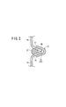
- FIG. 2 is a partially omitted sectional view showing the band coupling 10 and its periphery when the band coupling 10 is attached to the container 12.
- the filter 14 has a function of filtering and discharging the inflowing liquid with a built-in filter element.
- the application example of the container 12 is not limited to the filter 14 and may be, for example, a heat treatment apparatus or a boiler.
- the filter 14 includes a container 12 containing a filter element (not shown), and a plurality of legs 16 attached to the lower part of the container 12 and supporting the container 12 in an upright state.
- the container 12 includes a cylindrical container body 18 having an open upper end, a dome-shaped container lid 20 that hermetically closes an opening at the upper end of the container body 18, and a band coupling 10 that couples the container body 18 and the container lid 20.
- a first flange portion 19 that bulges outward in the radial direction is formed at the upper end of the container body 18 over the entire circumference, and a second portion that bulges outward in the radial direction at the lower end portion of the container lid 20.
- a flange portion 21 is formed over the entire circumference.
- the first flange portion 19 has a flare shape that spreads upward
- the second flange portion 21 has a flare shape that spreads downward.
- the opposing surfaces of the second flange portion 21 may be formed on surfaces that are perpendicular to the axis of the container 12.
- an O-ring 22 is interposed between the container lid 20 and the container body 18 as an annular seal member.
- the sealing member interposed between the container lid 20 and the container main body 18 is not limited to the O-ring, and may be a gasket.
- the container body 18 and the container lid 20 are coupled by a band coupling 10.
- the band coupling 10 is detachable with respect to the container 12, and couples the container body 18 and the container lid 20 to each other by sandwiching the periphery of the first flange part 19 and the second flange part 21 together. Is.
- the band coupling 10 is tightened, the container lid 20 and the container body 18 are firmly fixed, and the container 12 is closed in an airtight manner.
- an air vent valve 24 is provided for making the internal pressure zero when the container 12 is opened for maintenance or the like.
- a filter element (not shown) for removing foreign matter (solid component) from the liquid to be processed is disposed inside the container body 18.
- the liquid to be processed is a liquid in which foreign matters such as solid components are mixed, and examples thereof include a coolant liquid, a cleaning liquid, cutting oil, and industrial water.
- the processing target is not limited to a liquid, and may be a gas mixed with foreign matter.
- An introduction port 26 for introducing a liquid to be processed is provided so as to protrude from the upper side of the outer peripheral surface of the container body 18.
- a discharge port 28 for discharging the processed liquid is provided to protrude from the lower side of the outer peripheral surface of the container body 18.
- the filter element is disposed on the liquid flow path between the inlet 26 and the outlet 28 in the container 12.
- the lower part of the container body 18 is further provided with a liquid outlet 30 for discharging the liquid accumulated in the container 12 when maintenance is performed.
- Dedicated pipes (not shown) are connected to the introduction port 26, the discharge port 28, and the liquid discharge port 30, respectively.
- the container body 18 is further provided with a first pressure gauge 25 that measures the pressure of the liquid before passing through the filter element, and a second pressure gauge 27 that measures the pressure of the liquid after passing through the filter element. ing.
- the filter 14 configured as described above, when a liquid to be processed containing foreign matter (solid component) is introduced into the container 12 through the inlet 26, the foreign matter is captured by the filter element, so that solid-liquid separation is performed. Made. That is, the liquid is filtered to remove foreign matters in the liquid. The liquid filtered by the filter element is discharged to the outside through the discharge port 28.
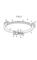
- FIG. 3 is an overall perspective view of the band coupling 10 according to an embodiment of the present invention.
- the band coupling 10 is a retainer that can surround both the first flange portion 19 and the second flange portion 21 around the first flange portion 19 and the second flange portion 21. 32 and a tightening mechanism 34 for tightening the retainer 32.
- the retainer 32 has a first end portion 36 constituting one end and a second end portion 38 constituting the other end, and exhibits a substantially annular shape as a whole when mounted on the container 12.
- a fitting groove 40 that fits the first flange portion 19 and the second flange portion 21 is formed in the inner peripheral portion of the retainer 32.
- the cross-sectional shape of the retainer 32 is V-shaped or U-shaped (see FIG. 2).
- the retainer 32 includes a plurality of arc-shaped retainer segments 42 and a connecting portion 44 that rotatably connects the end portions of the plurality of retainer segments 42.
- two connecting portions 44 are disposed between the three retainer segments 42.
- the number of the retainer segments 42 may be two, or four or more. In this case, the number of connecting portions 44 is the number obtained by subtracting 1 from the number of retainer segments 42.
- the constituent material of the retainer segment 42 is not particularly limited, and examples thereof include stainless steel, aluminum alloy, and copper alloy.
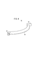
- the retainer segment 42 has a fitting groove 40 (see FIGS. 2 and 3) that fits in the first flange portion 19 and the second flange portion 21 and extends in an arc shape. And a projecting end portion 48 that is bent and protrudes radially outward from both ends of the arc portion 46.
- the arc portion 46 is set in shape so as to be fitted to the outer peripheral portions of the first flange portion 19 and the second flange portion 21.
- the cross section of the protruding end portion 48 in the illustrated example is a portal shape, but may be a U-shaped or V-shaped cross section.
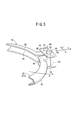
- FIG. 5 is a partially omitted perspective view showing the connecting portion 44 of the band coupling 10 and its periphery.
- the connecting portion 44 includes a connecting portion main body 50 and a pin 52.
- the connecting portion main body 50 includes an upper end plate 54 that covers the upper surfaces of the protruding end portions 48 of the two retainer segments 42 in common, a lower end plate 56 that covers the lower surfaces of the protruding end portions 48 of the two retainer segments 42 in common, and an upper end plate. 54 and a connecting plate 58 for connecting the lower end plate 56 to each other.
- the upper end plate 54, the connecting plate 58, and the lower end plate 56 are preferably continuous members.
- a pin 52 is inserted through the upper end plate 54, the projecting end portion 48, and the lower end plate 56 on one side and the other side in the width direction of the connecting portion 44 (the arrow Y direction in FIG. 5).
- the connection part 44 and the retainer segment 42 of the both sides are connected rotatably. Since the retainer 32 is configured as described above, the angular interval between the retainer segments 42 can be enlarged and reduced.
- the connecting portion 44 is further provided with a stopper portion 60 that restricts the rotation range of the retainer segment 42.
- the stopper portion 60 in the illustrated example is a plate-like body extending in the X direction from both ends of the connection plate 58, and at least partially connects both ends (end portions in the Y direction) of the connection portion 44 (connection portion main body 50). Closed.
- the stopper portion 60 and the connecting plate 58 are continuous and integral members, but those manufactured as separate parts may be joined by appropriate joining means (for example, welding or the like).
- the stopper portion 60 may be an integral member continuous with the upper end plate 54 and the lower end plate 56, or those manufactured separately from the upper end plate 54 and the lower end plate 56 are joined by an appropriate joining means. May be.
- the rotation range of the retainer segment 42 is restricted. That is, the retainer segment 42 shown on the front side in FIG. 5 will be described with reference numeral 42a in particular.
- the retainer segment 42a When the retainer segment 42a is rotated in the A direction to some extent from the state of FIG. Since the projecting end portion 48 of 42a (or a portion in the vicinity of the boundary between the projecting end portion 48 and the arc portion 46) abuts against the stopper portion 60 of the connecting portion 44, the retainer segment 42a rotates in the A direction at that position. Is limited.
- the rotation range of the retainer segments 42 other than the retainer segment 42a is similarly limited.
- the stopper portion 60 may extend in the X direction so that both ends of the connecting portion 44 (connecting portion main body 50) are completely closed, but when both ends of the connecting portion 44 are completely closed, The rotation range of the retainer segment 42 is narrowed. For this reason, the range in which the stopper portion 60 is provided is determined in consideration of the maximum rotation position of the retainer segment 42.
- FIG. 6A is a partially omitted perspective view showing the tightening mechanism 34 of the band coupling 10 and its periphery.
- FIG. 6B is a partially omitted perspective view showing a cross section of the tightening mechanism 34 of the band coupling 10 and its periphery.
- the tightening mechanism 34 includes a stopper 64 and a push bolt 66.
- the stopper 64 is rotatably attached to the first end portion 36 of the retainer 32.
- the stopper 64 in the illustrated example includes an upper plate 68 positioned above the first end portion 36 of the retainer 32, a lower plate 70 positioned below the first end portion 36 of the retainer 32, and an upper plate 68 and a lower plate.
- 70 is a gate-shaped part having a connection plate 72 for connecting 70, and is the distance between the upper plate 68 and the lower plate 70 substantially the same as the width in the height direction of the first end portion 36 and the second end portion 38? It is set slightly larger.
- the connecting plate 72 is provided with a through hole 74 through which the push bolt 66 is inserted, and a nut 76 is fixed to the rear surface (the inner surface of the stopper 64).
- the nut 76 may be fixed to the front surface of the connecting plate 72 (the outer surface of the stopper 64). Further, when the connecting plate 72 is thick enough to be provided with a screw portion, the nut 76 may be omitted, and a female screw portion may be provided in the connecting plate 72 itself.
- the stopper 64 is rotatably connected to the first end 36 of the retainer 32 at one end where the pin 78 is inserted. Since the stopper 64 is configured as described above, by rotating, the stopper 64 is disengaged from the second end portion 38 of the retainer 32 and the state in which the second end portion 38 of the retainer 32 is accommodated (in FIG. 6A). It can be any of the states shown).
- the push bolt 66 can be inserted into the through hole 74 of the stopper 64 and can be screwed into the nut 76 of the stopper 64. Therefore, the push bolt 66 can be screwed to the stopper 64 so as to be able to advance and retract.
- a head 80 of the push bolt 66 is formed with a hexagon hole 82 for inserting a hexagon wrench to rotate the push bolt 66.
- the push bolt 66 may be a hexagon bolt in which the head 80 is formed in a hexagonal column.
- the retainer 32 is fitted to the first flange portion 19 and the second flange portion 21, and the second end portion 38 is accommodated in the stopper 64.
- the actuator 66 is advanced into the stopper 64 while rotating 66, the second end 38 is pressed toward the first end 36 by the tip of the push bolt 66.
- the second end 38 of the retainer 32 is provided with a protrusion 84 that is caught by the push bolt 66 when the push bolt 66 presses the second end 38.
- the protruding portion 84 in the illustrated example is configured as a hollow cylindrical portion 84a.
- the hollow cylindrical portion 84a is preferably formed in a hollow cylindrical shape as shown in FIG. 6A.
- the hollow portion of the hollow cylindrical portion 84a has such a size that the tip of the push bolt 66 can be inserted, and is set to be approximately the same as or slightly larger than the outer diameter of the tip of the push bolt 66.
- a recessed portion 86 that is shallow and recessed is provided at a position of the second end portion 38 of the retainer 32 that is pressed by the push bolt 66.
- the hollow cylindrical portion 84a is not limited to the hollow cylindrical shape, and may be another hollow cylindrical shape (for example, a hollow square cylindrical shape) into which the tip of the push bolt 66 can be inserted.
- the protruding portion 84 is not limited to the hollow cylindrical shape, but protrudes from the outer wall surface of the second end portion 38 and contacts the side surface of the front end portion of the push bolt 66 (the side surface in the direction in which the stopper 64 is detached from the second end portion 38). What is necessary is just to be comprised so that it can prevent that the stopper 64 rotates in the direction which remove
- the band coupling 10 according to the present embodiment is basically configured as described above, and the operation and effect will be described next.
- the retainer 32 When the container main body 18 and the container lid 20 of the container 12 are coupled by the band coupling 10, the retainer 32 is sufficiently widened with the first end 36 and the second end 38 of the retainer 32 separated. At this time, the rotation range of the retainer segment 42 is limited by the stopper portion 60, so that the retainer 32 does not open too much. For this reason, handling is easy and usability is good. Further, as described above, since the stopper portion 60 is provided so as to cover the end portion (projecting end portion 48) of the retainer segment 42, the stopper portion 60 causes the connecting portion 44 and the end portion of the retainer segment 42 to be connected. The gap formed between the two is narrowed. Thereby, the user's fingers can be prevented from entering the gap, and the user can handle the band coupling 10 with peace of mind.
- the band coupling 10 is formed by fitting the fitting groove 40 of the retainer 32 to the first flange part 19 and the second flange part 21 with the container lid 20 closing the upper opening of the container body 18. Is mounted on the outer periphery of the container 12. In this case, since each retainer 32 is rotatably connected via the connecting portion 44, the retainer 32 can be easily spread with a small force. For this reason, mounting
- the retainer 32 is tightened by the tightening mechanism 34, whereby the first flange portion 19 and the second flange portion 21 are strongly pressed by the retainer 32, and the container body 18 and the container lid 20 to each other.
- the tightening mechanism 34 is operated as follows.
- the push bolt 66 is loosened to an appropriate position so that the stopper 64 can be rotated and moved to a position where the stopper 64 accommodates the second end portion 38. In this case, if necessary, the push bolt 66 may be loosened to the maximum, or the push bolt 66 may be removed from the stopper 64. Next, the stopper 64 is rotated so that the second end 38 is positioned inside the stopper 64.
- the push bolt 66 is moved in a direction to advance into the stopper 64, and the second end 38 is pressed toward the first end 36 by the tip of the push bolt 66. Then, the first end portion 36 and the second end portion 38 are attracted to each other, and the retainer 32 is tightened.
- the retainer 32 is sufficiently tightened, the tightening operation by the push bolt 66 is stopped. In this case, a mark is attached to the push bolt 66 so that the position of the push bolt 66 when the tightening amount is optimum can be recognized, or the tightening amount is increased when the push bolt 66 is inserted into the stopper 64 to the maximum. It is preferable to set the length of the push bolt 66 so as to be optimal.
- the container body 18 and the container lid 20 are firmly coupled by the band coupling 10. Thereafter, when a predetermined process is performed in the container 12, the inside of the container 12 is set to a high pressure.
- the container 12 is configured as a filter container, the liquid to be filtered is introduced into the high-pressure container 12 through the inlet 26, the fluid is filtered by the filter element, and the filtered liquid. Is discharged from the discharge port 28.
- the air vent valve 24 is operated to open the container 12 to the atmosphere.
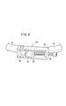
- FIG. 7A shows a state in which the push bolt 66 is loosened halfway.
- FIG. 7B shows a state where the push bolt 66 is completely loosened.
- the projecting portion 84 (hollow cylindrical portion 84a) is provided at the second end portion 38 of the retainer 32, even if the push bolt 66 is loosened halfway as shown in FIG. As shown in FIG. 7B, the engagement between the push bolt 66 and the second end 38 is not completed when the push bolt 66 is completely loosened. Canceled.
- the stopper 64 is provided with the second end 38. It will not come off. Even if it is forgotten to release the high pressure in the container 12, when the push bolt 66 is completely loosened, the airtightness between the container body 12 and the container lid 20 is already released, The internal pressure in the container 12 is released. Therefore, the container lid 20 is prevented from being lifted and the band coupling 10 is prevented from falling off at an unintended timing.
- FIG. 8 is a partially omitted perspective view showing the tightening mechanism 100 and its periphery according to the first comparative example.
- the tightening mechanism 100 according to the first comparative example has a configuration in which the protruding portion 84 is omitted from the tightening mechanism 34 of the band coupling 10 according to the present embodiment. Since these are the same, portions common to the tightening mechanism 34 are denoted by the same reference numerals, and detailed description thereof is omitted.
- the protruding portion 84 is provided at the second end portion 38 of the retainer 32, as described above, even if the push bolt 66 is loosened halfway, The stopper 64 does not come off from the second end portion 38, thereby preventing the container lid 20 from being lifted and the band from dropping off at an unintended timing.
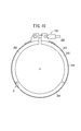
- FIG. 10 is an overall plan view of the band coupling 200 according to the second comparative example.
- the band coupling 200 includes an annular retainer 203 including a plurality of retainer pieces 202, a band 204 attached to the outer periphery of the retainer 203, and a tightening mechanism 206 for tightening the band 204.
- an annular retainer 203 including a plurality of retainer pieces 202, a band 204 attached to the outer periphery of the retainer 203, and a tightening mechanism 206 for tightening the band 204.
- FIG. 11 is a partially omitted cross-sectional view showing the band coupling 200 and its periphery when the band coupling 200 is attached to the pressure vessel 210.
- an O-ring is interposed between a container side flange portion 214 provided at the upper end of the container main body 212 of the pressure vessel 210 and a lid side flange portion 218 provided at the lower end of the container lid 216.
- the retainer piece 202 is fitted to the outer periphery of the container side flange portion 214 and the lid side flange portion 218.
- the retainer part 202 is fitted to the container side flange part 214 and the lid side flange part 218, and both flange parts are strongly tightened.
- the retainer part 202 receives a load directly from the container side flange part 214 and the lid side flange part 218.
- the retainer piece 202 is deformed so as to open up and down.
- the retainer segment 42 of the band coupling 10 includes an arc portion 46 and protruding end portions 48 at both ends thereof.
- the arc portion 46 that contacts the first flange portion 19 and the second flange portion 21.
- the load is directly received from the first flange portion 19 and the second flange portion 21.
- the projecting end portion 48 projects radially outward from the arc portion 46, it does not contact the first flange portion 19 and the second flange portion 21, and from the first flange portion 19 and the second flange portion 21. Since it does not receive a load directly and elastic deformation does not occur, cracks due to fatigue do not occur.
- the retainer 32 constituted by the retainer segment 42 has a high strength. Therefore, it is possible to reduce the thickness of the retainer segment 42, and as a result, it is possible to reduce the manufacturing cost. Further, since the total weight of the band coupling 10 is reduced by reducing the thickness of the retainer segment 42, the handling of the band coupling 10 becomes easier and the usability is further improved.
Landscapes
- Engineering & Computer Science (AREA)
- General Engineering & Computer Science (AREA)
- Mechanical Engineering (AREA)
- Pressure Vessels And Lids Thereof (AREA)
- Clamps And Clips (AREA)
- Closures For Containers (AREA)
- Filling Or Discharging Of Gas Storage Vessels (AREA)
Abstract
Description
Claims (7)
- 第1フランジ部(19)を有する容器本体(18)と、第2フランジ部(21)を有する容器蓋(20)とを、前記第1フランジ部(19)と前記第2フランジ部(21)の周囲を共に挟持することによって、相互に結合するバンドカップリング(10)であって、
前記第1フランジ部(19)及び前記第2フランジ部(21)の周囲を略一周取り巻いて、前記第1フランジ部(19)及び前記第2フランジ部(21)に共に嵌合可能なリテーナ(32)と、
前記リテーナ(32)を引き締めるための引締機構(34)とを備え、
前記リテーナ(32)は、前記引締機構(34)が連結された一端を構成する第1端部(36)と、引締時に前記第1端部(36)と相対し、外側に屈曲した他端を構成する第2端部(38)とを有し、
前記引締機構(34)は、
前記リテーナ(32)の前記第1端部(36)に回動自在に取り付けられたストッパ(64)と、
前記ストッパ(64)に対して進退調節自在に螺合し、前記リテーナ(32)が前記第1フランジ部(19)及び前記第2フランジ部(21)に嵌合した状態で、前記第2端部(38)を前記第1端部(36)側に押圧するための押しボルト(66)とを有し、
前記第2端部(38)には、前記押しボルト(66)が前記第2端部(38)を押圧するときに前記押しボルト(66)に引っ掛かる突出部(84)が設けられている、
ことを特徴とするバンドカップリング。 - 請求項1記載のバンドカップリング(10)において、
前記突出部(84)は中空筒状部(84a)である、
ことを特徴とするバンドカップリング。 - 請求項1記載のバンドカップリング(10)において、
前記リテーナ(32)は、円弧状の複数のリテーナセグメント(42)と、前記複数のリテーナセグメント(42)の端部同士を回動自在に連結する連結部(44)とを有する、
ことを特徴とするバンドカップリング。 - 請求項3記載のバンドカップリング(10)において、
前記連結部(44)は、前記リテーナセグメント(42)の回動範囲を規制するストッパ部(60)を有する、
ことを特徴とするバンドカップリング。 - 請求項4記載のバンドカップリング(10)において、
前記ストッパ部(60)は、前記リテーナセグメント(42)の端部を覆うように設けられている、
ことを特徴とするバンドカップリング。 - 請求項3記載のバンドカップリング(10)において、
前記各リテーナセグメント(42)は、前記第1フランジ部(19)及び前記第2フランジ部(21)に嵌合する嵌合溝(40)を有し且つ円弧状に延在する円弧部(46)と、前記円弧部(46)の両端から外側に屈曲して突出する突出端部(48)とを有する、
ことを特徴とするバンドカップリング。 - 第1フランジ部(19)を有する容器本体(18)と、
第2フランジ部(21)を有する容器蓋(20)とを備えた圧力容器において、
請求項1記載のバンドカップリング(10)を備えた、
ことを特徴とする圧力容器。
Priority Applications (6)
| Application Number | Priority Date | Filing Date | Title |
|---|---|---|---|
| US13/502,762 US8763839B2 (en) | 2009-10-22 | 2009-10-22 | Band coupling and pressure container with same |
| CN200980162063.4A CN102575769B (zh) | 2009-10-22 | 2009-10-22 | 带状联接器和利用该带状联接器的压力容器 |
| DE112009005287.8T DE112009005287B9 (de) | 2009-10-22 | 2009-10-22 | Bandkupplung und damit ausgestatteter Druckbehälter |
| PCT/JP2009/068195 WO2011048686A1 (ja) | 2009-10-22 | 2009-10-22 | バンドカップリング及びこれを備えた圧力容器 |
| JP2011537066A JP5517135B2 (ja) | 2009-10-22 | 2009-10-22 | バンドカップリング及びこれを備えた圧力容器 |
| KR1020127009901A KR101375816B1 (ko) | 2009-10-22 | 2009-10-22 | 밴드 커플링 및 이것을 구비한 압력 용기 |
Applications Claiming Priority (1)
| Application Number | Priority Date | Filing Date | Title |
|---|---|---|---|
| PCT/JP2009/068195 WO2011048686A1 (ja) | 2009-10-22 | 2009-10-22 | バンドカップリング及びこれを備えた圧力容器 |
Publications (1)
| Publication Number | Publication Date |
|---|---|
| WO2011048686A1 true WO2011048686A1 (ja) | 2011-04-28 |
Family
ID=43899933
Family Applications (1)
| Application Number | Title | Priority Date | Filing Date |
|---|---|---|---|
| PCT/JP2009/068195 Ceased WO2011048686A1 (ja) | 2009-10-22 | 2009-10-22 | バンドカップリング及びこれを備えた圧力容器 |
Country Status (6)
| Country | Link |
|---|---|
| US (1) | US8763839B2 (ja) |
| JP (1) | JP5517135B2 (ja) |
| KR (1) | KR101375816B1 (ja) |
| CN (1) | CN102575769B (ja) |
| DE (1) | DE112009005287B9 (ja) |
| WO (1) | WO2011048686A1 (ja) |
Cited By (1)
| Publication number | Priority date | Publication date | Assignee | Title |
|---|---|---|---|---|
| US20240288128A1 (en) * | 2023-02-26 | 2024-08-29 | Kyle Brown | Pressure relief system, pressure safety device and tool, pressurized container system, processes, and method of use |
Families Citing this family (9)
| Publication number | Priority date | Publication date | Assignee | Title |
|---|---|---|---|---|
| RU2477416C1 (ru) * | 2009-03-11 | 2013-03-10 | Авуре Текнолоджиз Аб | Сосуд высокого давления для пресса высокого давления |
| CN103821930A (zh) * | 2012-11-19 | 2014-05-28 | 韦兆玖 | 一种分段连续环槽压力容器快开门机构 |
| US10688212B2 (en) | 2017-06-30 | 2020-06-23 | O&M Halyard, Inc. | Filter-gasket assembly with seal and placement indicator for sterilization rigid container |
| JP7381558B2 (ja) | 2018-07-31 | 2023-11-15 | オーアンドエム ハリヤード インコーポレイテッド | 滅菌容器用の密閉完全性表示器 |
| US11338051B2 (en) | 2018-11-09 | 2022-05-24 | O&M Haylard, Inc. | Closure mechanisms and seal integrity indicators for sterilization containers |
| US10939975B2 (en) | 2019-03-06 | 2021-03-09 | O&M Halyard, Inc. | Disposable gasket-filter assembly with seal integrity indication for sterilization container with slidable lock handles |
| US20220412126A1 (en) * | 2021-06-29 | 2022-12-29 | Inner-Tite Corp. | Multi-segmented meter ring |
| CN113664507B (zh) * | 2021-07-12 | 2022-07-19 | 合肥通用机械研究院有限公司 | 一种超高压容器预紧装置及应用该装置的预紧方法 |
| CN118188807B (zh) * | 2024-05-20 | 2024-07-16 | 河北安信燃气设备有限公司 | 一种齿式旋转快开盲板的安全联锁装置 |
Citations (3)
| Publication number | Priority date | Publication date | Assignee | Title |
|---|---|---|---|---|
| JPS56500024A (ja) * | 1979-02-22 | 1981-01-08 | ||
| JPS6252060A (ja) * | 1985-08-19 | 1987-03-06 | 日東金属工業株式会社 | 試験用密閉容器の封緘装置 |
| JPH0640519U (ja) * | 1992-11-05 | 1994-05-31 | 石川島播磨重工業株式会社 | 急速開閉蓋装置 |
Family Cites Families (10)
| Publication number | Priority date | Publication date | Assignee | Title |
|---|---|---|---|---|
| US1547048A (en) | 1923-10-06 | 1925-07-21 | Klein Alfred | Safety latch for windows |
| US1901699A (en) * | 1931-03-30 | 1933-03-14 | Burper Can Sealer Company | Cover clamp for pressure cooking vessels |
| CA1039974A (en) | 1975-12-30 | 1978-10-10 | Charles E. Meginnis | Quick-opening sight glass assembly |
| US4415190A (en) * | 1981-04-06 | 1983-11-15 | Highfield Mfg. Company, Div. Of Clarkson Industries, Inc. | Lockable ring assembly for electric meter |
| JPH0723415Y2 (ja) | 1990-11-27 | 1995-05-31 | エスエムシー株式会社 | 吹き飛び防止機構付き連結装置 |
| US5193864A (en) * | 1991-05-28 | 1993-03-16 | Coleman Clarence B | Split lock ring for bulk material container |
| JPH0640519A (ja) | 1992-06-12 | 1994-02-15 | Murata Mach Ltd | ガイドレールに沿って走行する走行台車の車輪ユニット |
| JP2531096B2 (ja) | 1993-07-01 | 1996-09-04 | 日本電気株式会社 | 動き検出回路 |
| JPH11255256A (ja) | 1998-03-09 | 1999-09-21 | Raisen:Kk | ドラム缶用バンド |
| JP4168385B2 (ja) | 2003-03-17 | 2008-10-22 | Smc株式会社 | バンドカップリング |
-
2009
- 2009-10-22 DE DE112009005287.8T patent/DE112009005287B9/de active Active
- 2009-10-22 WO PCT/JP2009/068195 patent/WO2011048686A1/ja not_active Ceased
- 2009-10-22 US US13/502,762 patent/US8763839B2/en active Active
- 2009-10-22 CN CN200980162063.4A patent/CN102575769B/zh active Active
- 2009-10-22 KR KR1020127009901A patent/KR101375816B1/ko active Active
- 2009-10-22 JP JP2011537066A patent/JP5517135B2/ja not_active Expired - Fee Related
Patent Citations (3)
| Publication number | Priority date | Publication date | Assignee | Title |
|---|---|---|---|---|
| JPS56500024A (ja) * | 1979-02-22 | 1981-01-08 | ||
| JPS6252060A (ja) * | 1985-08-19 | 1987-03-06 | 日東金属工業株式会社 | 試験用密閉容器の封緘装置 |
| JPH0640519U (ja) * | 1992-11-05 | 1994-05-31 | 石川島播磨重工業株式会社 | 急速開閉蓋装置 |
Cited By (1)
| Publication number | Priority date | Publication date | Assignee | Title |
|---|---|---|---|---|
| US20240288128A1 (en) * | 2023-02-26 | 2024-08-29 | Kyle Brown | Pressure relief system, pressure safety device and tool, pressurized container system, processes, and method of use |
Also Published As
| Publication number | Publication date |
|---|---|
| DE112009005287B4 (de) | 2021-10-07 |
| JPWO2011048686A1 (ja) | 2013-03-07 |
| CN102575769B (zh) | 2015-01-28 |
| DE112009005287T5 (de) | 2013-01-03 |
| KR20130028036A (ko) | 2013-03-18 |
| JP5517135B2 (ja) | 2014-06-11 |
| CN102575769A (zh) | 2012-07-11 |
| KR101375816B1 (ko) | 2014-04-01 |
| US8763839B2 (en) | 2014-07-01 |
| DE112009005287B9 (de) | 2022-03-03 |
| US20120205379A1 (en) | 2012-08-16 |
Similar Documents
| Publication | Publication Date | Title |
|---|---|---|
| JP5517135B2 (ja) | バンドカップリング及びこれを備えた圧力容器 | |
| US4465595A (en) | Apparatus for assembly and dissassembly of a filter construction | |
| EP2576396B1 (en) | Swing bolt splash shield | |
| US9821256B2 (en) | Elastically deformable component providing indication of proper fluid filter installation and related methods | |
| KR20170141338A (ko) | 가스실린더 연결장치 | |
| JPH109717A (ja) | ルームクーラー用サービスバルブ | |
| CN201827356U (zh) | 压力容器 | |
| JP2011125792A (ja) | 縦形ストレーナ | |
| JP2023507512A (ja) | 接続構成部品組立体および処理容器 | |
| EP2646666B1 (en) | Insert, holder and post-treatment unit for exhaust gases | |
| JP6068822B2 (ja) | ストレーナ | |
| CN201396889Y (zh) | 一种卸荷阀 | |
| CN214367998U (zh) | 一种煤磨除尘器用防爆阀 | |
| JP5875836B2 (ja) | 流体装置 | |
| WO2017083578A1 (en) | Elastically deformable component providing indication of proper fluid filter installation and related methods | |
| JP4796611B2 (ja) | 円筒容器天蓋締付け装置 | |
| KR20100003990U (ko) | 탁주병 마개 | |
| JP5946263B2 (ja) | ストレーナ | |
| EP3374048B1 (en) | Elastically deformable component providing indication of proper fluid filter installation and related methods | |
| CN222543288U (zh) | 一种快速接头 | |
| JP2002177715A (ja) | ストレーナ | |
| JP6112827B2 (ja) | 閉塞処理装置 | |
| JP2024520229A5 (ja) | ||
| JPH0514789U (ja) | ストレーナ | |
| JPH0514788U (ja) | ストレーナ |
Legal Events
| Date | Code | Title | Description |
|---|---|---|---|
| WWE | Wipo information: entry into national phase |
Ref document number: 200980162063.4 Country of ref document: CN |
|
| 121 | Ep: the epo has been informed by wipo that ep was designated in this application |
Ref document number: 09850584 Country of ref document: EP Kind code of ref document: A1 |
|
| WWE | Wipo information: entry into national phase |
Ref document number: 2011537066 Country of ref document: JP |
|
| ENP | Entry into the national phase |
Ref document number: 20127009901 Country of ref document: KR Kind code of ref document: A |
|
| WWE | Wipo information: entry into national phase |
Ref document number: 13502762 Country of ref document: US |
|
| WWE | Wipo information: entry into national phase |
Ref document number: 1120090052878 Country of ref document: DE Ref document number: 112009005287 Country of ref document: DE |
|
| WWE | Wipo information: entry into national phase |
Ref document number: 4375/CHENP/2012 Country of ref document: IN |
|
| 122 | Ep: pct application non-entry in european phase |
Ref document number: 09850584 Country of ref document: EP Kind code of ref document: A1 |