WO2011040027A1 - Flow rate measuring device - Google Patents
Flow rate measuring device Download PDFInfo
- Publication number
- WO2011040027A1 WO2011040027A1 PCT/JP2010/005880 JP2010005880W WO2011040027A1 WO 2011040027 A1 WO2011040027 A1 WO 2011040027A1 JP 2010005880 W JP2010005880 W JP 2010005880W WO 2011040027 A1 WO2011040027 A1 WO 2011040027A1
- Authority
- WO
- WIPO (PCT)
- Prior art keywords
- flow rate
- measurement
- unit
- time
- time difference
- Prior art date
Links
Images


Classifications
-
- G—PHYSICS
- G01—MEASURING; TESTING
- G01F—MEASURING VOLUME, VOLUME FLOW, MASS FLOW OR LIQUID LEVEL; METERING BY VOLUME
- G01F1/00—Measuring the volume flow or mass flow of fluid or fluent solid material wherein the fluid passes through a meter in a continuous flow
- G01F1/66—Measuring the volume flow or mass flow of fluid or fluent solid material wherein the fluid passes through a meter in a continuous flow by measuring frequency, phase shift or propagation time of electromagnetic or other waves, e.g. using ultrasonic flowmeters
- G01F1/667—Arrangements of transducers for ultrasonic flowmeters; Circuits for operating ultrasonic flowmeters
-
- G—PHYSICS
- G01—MEASURING; TESTING
- G01F—MEASURING VOLUME, VOLUME FLOW, MASS FLOW OR LIQUID LEVEL; METERING BY VOLUME
- G01F1/00—Measuring the volume flow or mass flow of fluid or fluent solid material wherein the fluid passes through a meter in a continuous flow
- G01F1/66—Measuring the volume flow or mass flow of fluid or fluent solid material wherein the fluid passes through a meter in a continuous flow by measuring frequency, phase shift or propagation time of electromagnetic or other waves, e.g. using ultrasonic flowmeters
- G01F1/667—Arrangements of transducers for ultrasonic flowmeters; Circuits for operating ultrasonic flowmeters
- G01F1/668—Compensating or correcting for variations in velocity of sound
Definitions
- the present invention relates to a flow rate measuring device that measures the flow rate of a fluid based on the propagation time of an ultrasonic signal.
- the first vibrator 102 that transmits ultrasonic waves and the second vibrator 103 that receives the transmitted ultrasonic waves are provided in the middle of the fluid conduit 101 so as to face the upstream and downstream sides in the flow direction.
- the ultrasonic waves cross the fluid diagonally.
- the flow rate of the fluid based on the measurement unit 104 that measures the ultrasonic propagation time using the first and second vibrators 102 and 103, the control unit 105 that controls the measurement unit 104, and the measurement result of the measurement unit 104. It is comprised with the calculating part 106 which calculates
- the sound velocity is C
- the flow velocity is v
- the distance between the first and second vibrators 102 and 103 is L
- the angle between the ultrasonic wave propagation direction and the flow direction is ⁇
- the upstream of the fluid conduit 101 is C
- the propagation time is t 1
- the reverse propagation time is t 2
- T 1 and t 2 can be obtained by the following equations.
- the measurement unit 104 needs to have a very small time resolution on the order of ns (nanoseconds), for example, to measure as a single-shot phenomenon.
- the required time resolution is realized by obtaining the average value. That is, if the time resolution of the measurement unit 104 is T A and the number of repetitions is M, the measurement resolution of the propagation time is T A / M by continuously operating the measurement unit 104 during this repeated measurement. be able to.
- This type of measuring device can achieve highly accurate measurement when the pressure in the fluid flow path is stable. For example, when applied to a gas meter that measures the flow rate of gas supplied to an ordinary household as an energy source. Face an inherent challenge called the pulsation phenomenon.
- GHP gas engine
- the gas moves in the pipe in synchronization with the pressure fluctuation, and it is affected by the movement as if the gas is flowing. A measurement value is detected.
- the number of repeated measurements M is suppressed to the minimum number that can maintain the measurement accuracy, and then the measurement interval is shortened and executed N times continuously for a relatively long time in small increments. Then, the flow rate calculation is performed using the N measurement results continuously measured.
- the phase state of the flow velocity fluctuation waveform can be captured evenly, and by averaging them, the true flow velocity with the fluctuation component removed
- the effect of detecting (flow rate) is aimed (see, for example, Patent Document 1).
- the number N of times of measurement is controlled according to the detected fluctuation amount of the flow velocity.
- the measurement number N is reduced under a situation where the flow rate fluctuation is small and it can be determined that there is no pulsation, and the measurement number N is increased under a situation where the flow rate fluctuation is judged to be large and pulsation (for example, , See Patent Document 2).
- Patent Document 1 Japanese Patent Laid-Open No. 2002-350202 Patent Document 2 Japanese Patent Laid-Open No. 2003-222548
- the present invention solves the above-described conventional problems, and provides a highly responsive measuring device that can quickly determine the presence or absence of a flow rate and switch to a measurement method that effectively uses power resources according to the presence or absence of the flow rate.
- the purpose is to do.
- a flow rate measuring device includes a first transducer and a second transducer that are provided in a fluid flow path and transmit and receive an ultrasonic signal, and an ultrasonic signal between the transducers.
- a time measuring means for measuring the propagation time of the two a unit measuring step for measuring the propagation time of the forward and reverse bidirectional ultrasonic signals by the time measuring means while switching the transmission / reception direction of the two vibrators, and the unit measuring step.
- a flow rate calculating means for calculating a flow rate based on the propagation times for the number of executions, a time difference detecting means for obtaining a propagation time difference in both the forward and reverse directions of the unit measuring step, and a series of unit measurements executed continuously.
- a measurement control unit that selects an arbitrary unit measurement step from among the steps, and controls the number of executions of the subsequent unit measurement step based on the time difference obtained by the time difference detection unit in the arbitrary unit measurement step; It is a configuration that is equipped.
- the flow measurement device of the present invention can quickly determine the presence / absence of a flow rate and perform highly responsive measurement capable of switching to a measurement method according to the presence / absence of the flow rate.
- FIG. 2 is a time chart for explaining an example of a configuration of a flow rate calculation step in the operation of the flow rate measuring device shown in FIG. 1. It is a time chart explaining the measurement interval of the flow volume calculation process shown in FIG. It is a time chart explaining operation
- movement of the flow measuring device shown in FIG. 2 is a time chart for explaining the operation when the flow rate is zero in the flow rate measuring device shown in FIG. 1.
- FIG. 7 is a time chart for explaining the time chart shown in FIG. 7 in more detail in the time measuring means shown in FIG. It is a time chart explaining operation
- the present invention provides a first vibrator and a second vibrator that are provided in a fluid flow path and transmit and receive an ultrasonic signal, a time measuring unit that measures a propagation time of an ultrasonic signal between the vibrators, and both the vibrators
- the unit measurement step of measuring the propagation time of the forward and reverse bidirectional ultrasonic signals by the time measuring means while switching the transmission / reception direction of the signal, and the unit measurement step are continuously executed, based on the propagation time for the number of executions
- a flow rate calculation means for calculating a flow rate, a time difference detection means for obtaining a propagation time difference in both the forward and reverse directions of the unit measurement process, and an arbitrary unit measurement process is selected from a series of unit measurement processes that are continuously executed.
- the flow measurement device is configured to include measurement control means for controlling the number of executions of the subsequent unit measurement process based on the time difference obtained by the time difference detection means. Therefore, it is possible to perform measurement with high responsiveness by determining the presence or absence of a flow rate without a response delay and switching to a measurement method according to the presence or absence of the flow rate.
- the responsiveness can be further improved by setting the arbitrary unit measurement process as the initial unit measurement process in the series of unit measurement processes.
- the measurement control means aborts the execution of the subsequent measurement process. Therefore, it is possible to reduce power consumption when there is no flow rate.
- the flow rate calculation means calculates the flow rate between them as zero. Therefore, when there is no flow rate, complicated flow rate calculation can be saved, so that power consumption can be further reduced.
- the measurement control means changes the execution interval of the unit flow rate calculation process to be different each time. Therefore, even when periodic pulsation is generated in the flow path, the flow rate is not erroneously determined to be zero, and the measurement accuracy can be improved.
- the measurement control means continuously performs a plurality of unit measurement processes. Since it is configured to execute continuously, when there is a flow rate, highly accurate measurement is possible.
- the time measuring means is composed of a reference clock and a counter circuit that counts based on the clock
- the time difference detecting means is composed of a subtracting circuit using the count value of the counter circuit, and in the process of determining the flow rate zero. Since the multiplication / division is not required, the presence / absence of the flow rate can be determined by a simple calculation method that simply operates the subtraction circuit, so that high-speed control is possible.
- the time measuring means is composed of at least two reference clocks having different frequencies and a counter circuit
- the time difference detecting means calculates a time difference for each counter circuit
- the determining means is all the counters obtained by the time difference detecting means. Therefore, the determination accuracy of zero flow rate can be improved.
- FIG. 1 is a block diagram illustrating a configuration example of a flow rate measuring device according to the present embodiment.
- first and second transducers 2 and 3 that transmit and receive ultrasonic signals are obliquely disposed on the middle of the fluid flow path 1.
- the ultrasonic wave propagates diagonally across the fluid through which the ultrasonic waves flow.
- known piezoelectric ceramic vibrators that also transmit and receive ultrasonic waves can be suitably used, but are not particularly limited, and other known ultrasonic transmitting and receiving elements are used. Can be used.
- the transmission unit 4 outputs a drive signal to the first transducer 2, the second transducer 3 receives the ultrasonic signal output from the first transducer 2, and the reception signal is processed by the reception unit 5.
- the switching means 6 switches the transmission / reception roles of the first vibrator 2 and the second vibrator 3.
- the measurement control means 7 controls the overall transmission / reception operation executed between the first and second vibrators 2 and 3, and includes a trigger means 8, a repetition means 9, a delay means 10, and a measurement process control means 11. Has been.
- the switching means 6 connects the first vibrator 2 and the transmission means 4, the second vibrator 3 and the reception means 5, and the first vibrator 2 is connected. Measurement with the transmitting side and the second vibrator 3 as the receiving side is started. For the following description, this will be referred to as forward flow measurement.
- the forward means sing-around measurement consisting of a predetermined number of repetitions is executed by the operation of the repetition means 9.
- the number of repetitions is four. However, the number of repetitions is not limited to this. If the measurement resolution is high, only one measurement may be performed instead of the single-around measurement.
- the trigger means 8 When the four repetitions are completed, after a predetermined delay time is generated from the delay means 10, the trigger means 8 outputs a transmission / reception switching signal to the switching means 6, and this time, transmission with the second vibrator 3 is performed.
- the means 4, the first vibrator 2 and the receiving means 5 are connected to each other, and measurement is started with the second vibrator 3 as the transmitting side and the first vibrator 2 as the receiving side. For the following explanation, this will be referred to as measurement in the reverse direction of the flow.
- a trigger signal for starting measurement is output from the trigger means 8. Even in the measurement in the reverse direction in which the roles of transmission and reception are switched, four repeated measurements are executed.
- a series of operations in which the forward sing-around measurement (four repetitions measurement) and the reverse sing-around measurement (four repetitions) are alternately performed once are referred to as a unit measurement process.
- the unit measurement process and the flow rate calculation process will be described with reference to the flowcharts of FIGS.
- the unit measurement process executed first is the first measurement process
- a delay signal is output from the delay means 10 and the same operation as the first measurement process is repeated. This is the second measurement step. Since the same unit measurement process is repeated a prescribed number of times, the nth unit measurement process is referred to as the nth measurement process.
- the flow rate measuring device of the present invention measures the flow rate by executing this flow rate calculation step at regular measurement intervals.
- the length of the fixed measurement interval and the prescribed number of unit measurement steps are not particularly limited, and an appropriate time or number can be set according to various conditions.
- the time measuring means 12 measures the time from the trigger signal output timing of the trigger means 8 to the end of sing-around, and the first addition means 13 integrates the measured values of the time measuring means 12 in the forward measurement of each unit measuring step.
- the second adding means 14 integrates the measured values of the time measuring means 12 in the measurement in the reverse direction of each unit measurement process.
- the flow rate calculation means 15 calculates the flow value using the output values of the first addition means 13 and the second addition means 14.
- the time difference detection means 16 obtains the difference between the measurement value of the time measurement means 12 in the forward direction measurement and the measurement value of the time measurement means 12 in the reverse direction measurement.
- the determination means 17 compares the output of the time difference detection means 16 with a determination threshold value. If it is larger than the threshold value, it determines that there is a flow rate, and if it is smaller than the threshold value, it determines that there is no flow rate (zero flow rate). Output.
- the measurement process control means 11 sets how many times the unit measurement process is executed to obtain the flow rate according to the determination result of the determination means 17.
- the transmission means 4 As the transmission means 4, the reception means 5, the switching means 6 and the measurement control means 7 described above, specifically, a transmission circuit, a reception circuit, a switching circuit and a controller having a known configuration are used.
- the configuration is not particularly limited.
- the specific configurations of the trigger unit 8, the repetition unit 9, the delay unit 10, and the measurement process control unit 11 constituting the measurement control unit 7 are not particularly limited, and a known trigger output circuit, repetition control circuit, delay circuit, A circuit for setting the number of unit measurement steps may be used, and thereby a measurement control circuit may be configured.
- the trigger unit 8, The repeating unit 9, the delay unit 10, and the measurement process control unit 11 may be a functional configuration of the controller. That is, the trigger unit 8, the repetition unit 9, the delay unit 10, and the measurement process control unit 11 are realized by, for example, a CPU as a controller operating according to a program stored in a storage unit such as a memory (not shown). It may be a configuration.
- the first addition means 13, the second addition means 14, the flow rate calculation means 15, the time difference detection means 16, and the determination means 17 are realized by a single controller, like the measurement control means 7. It may be a functional configuration.
- the specific structure of the time measuring means 12 is mentioned later, this invention is not limited to this, Other well-known structures can also be employ
- the transmission means 4, the reception means 5, the switching means 6, the measurement control means 7 (and the trigger means 8, the repetition means 9, the delay means 10, and the measurement process control means 11), the time measurement means 12, the first The addition unit 13, the second addition unit 14, the flow rate calculation unit 15, the time difference detection unit 16, and the determination unit 17 are components included in the flow rate measurement device according to the present embodiment, and may include other components. Needless to say, these components constitute a circuit unit or a functional unit in the flow rate measuring device as described above.
- these constituent elements are, for example, a transmission unit or a transmitter, a reception unit or a receiver, a switching unit or a switch, a measurement control unit or a measurement controller (trigger unit, repetition unit, delay unit, And measuring process control unit), time measuring unit or timer, first or second adding unit or first or second adder, flow rate calculating unit or flow rate calculating unit, time difference detecting unit or time difference detector, and determining unit or determining unit Can be read as
- FIG. 4 is a time chart in which the horizontal axis is the elapsed time from the origin, and the vertical axis is the operation of each part with the output timing of the trigger means 8 indicating the start of measurement in the forward direction of the flow in the first measurement step as the origin.
- the forward measurement value T d1 of the first measurement process measured by the time measuring means 12 is output to the time difference detecting means 16 and at the same time T d1 is added to the first adding means 13. .
- a predetermined delay time T int elapsed time t 2 of the flow of the reverse direction measurement is started at time t3, the reverse direction of the measurement value T u1 time difference detection of the first measurement step measured by the time measuring means 12 It is output to the means 16.
- the time difference detection means 16 obtains the difference between the two measured values T d1 and T u1 , T dif1 using (Equation 5).
- T dif1 T u1 ⁇ T d1 (Formula 5)
- T u1 is added to the second addition means 14. Note that switching of control based on the time difference obtained using (Equation 5) will be described later.
- the addition process is alternately performed by the first addition unit 13 and the second addition unit 14 every time the measurement in the forward direction and the reverse direction is completed.
- the flow rate calculation means 15 calculates the flow rate.
- the flow rate calculating unit 15 compares the average value t 1 and t 2 per one transmission time from the value held in the respective first addition means 13 and the second addition means 14 is then obtained, and the (formula The flow rate is obtained by obtaining the flow velocity using 3) and further multiplying by a necessary coefficient.
- the reason why the flow rate calculation is not executed for each unit measurement step is to save power.
- the flow state (some physical quantity correlated with the flow rate) is sampled after setting T int shown in FIG. Although it is necessary to improve the accuracy by capturing the state, it is obvious that the calculation amount becomes enormous if the flow rate is obtained each time, resulting in an increase in power consumption.
- the propagation time is sampled at such a short interval, and the flow rate is calculated using the average value of the sampling results at a stage where the unit measurement process is repeated to some extent (for example, several tens of times), Compared with the case where the flow rate is calculated for each unit measurement process, the calculation amount can be dramatically reduced.
- the time difference detection means 16 obtains the propagation time difference T dif1 in the forward direction and the reverse direction using (Equation 5).
- FIG. 5 shows a time chart of the operation when T dif1 is smaller than the threshold value, that is, when there is no flow rate.
- the determination unit 17 compares T dif1 with a determination threshold value. As a result, if T dif1 is smaller than the determination threshold value, the measurement process control unit 11 performs the second measurement in the measurement control unit 7. Stop outputting trigger signals after the process. Thereby, the execution of the unit measurement process after the first measurement process is aborted. Further, the flow rate calculation means 15 does not execute any flow rate calculation including the above (Equation 3), and calculates the flow rate as zero.
- the execution interval when the unit measurement process is continuously executed is set to a value of about several ms, but after detecting the flow rate zero, the measurement control means 7 After placing this time than long enough time interval (e.g. 100 ms), and it controls to initiate the first measuring step at time t 4 corresponding to the start of the next rate calculation step.
- long enough time interval e.g. 100 ms
- the measurement control means 7 performs an operation based on the time chart shown in FIG. 4, that is, N unit measurement steps continuously at intervals of several ms. And control to execute.
- the time interval until the next flow rate calculation step is executed is not constant for 100 ms, and if it is always changed with a random value, In the case where periodic pulsations are generated, it is possible to prevent erroneous determination that the flow rate is zero even though the flow rate is generated.
- the measurement control means 7 selects the first measurement process as a series of unit measurement processes to be executed continuously.
- the present invention is not limited to this, and the second measurement process is not limited to this.
- a unit measurement process after the measurement process can be arbitrarily selected.
- the unit measurement process is repeated N times, even if the Nth measurement process is selected, the subsequent unit measurement process cannot be terminated. It is preferable that one of the unit measurement steps from the first time to the (N-1) th time is selected.
- the measurement control unit 7 is configured to select an initial unit measurement process as much as possible from a series of unit measurement processes.
- the initial term here may be any unit measurement step from the first time to an integer number smaller than N / 2 (that is, a time before half of all N times). If the upper limit value of the selectable number of times is N max , N max may be a maximum integer of at least less than N / 2, and may be an integer less than N / 3, for example, depending on the magnitude of N. It may be an integer smaller than N / 4 or a smaller integer.
- the measurement control means 7 is configured to abort the execution of the unit measurement process after an arbitrary unit measurement process.
- the number of executions can be controlled by a control other than aborting the execution. There may be. For example, there is a control in which the unit measurement process is stopped after being performed several times, the number of times is significantly reduced, or the number of times is thinned out under a preset condition.
- the presence or absence of flow volume can be determined substantially instantaneously, and based on this determination, it can switch to the measuring method according to the presence or absence of flow volume substantially instantaneously.
- the power consumption can be significantly reduced, it is only necessary to be configured to quickly determine whether or not there is a flow rate and to quickly switch to an appropriate measurement method, even if it is not instantaneous.
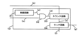
- the clock means 12 includes an oscillation circuit 31 that generates a clock signal (a), a signal (c) that switches supply / stop of the clock signal output from the oscillation circuit 31, and a clock signal (a).
- the gate circuit 32 includes an AND circuit, the counter circuit 33 counts the reference clock (d) output through the gate circuit 32, and the latch circuit 34 reads the count value of the counter circuit 33 at an appropriate timing.
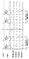
- 6A to 6G show digital signals transmitted between the time measuring means 12 and each component.
- the signal (b) becomes “L” and the counter circuit 33 is cleared.
- the clock (a) output from the oscillation circuit 31 is supplied to the counter circuit 33 as the reference clock (d) through the gate circuit 32. Is done.
- the counter circuit 33 is an up counter that is incremented by one count every time the reference clock is supplied. (E) shows the count value of the counter circuit 33.
- FIG. 7 shows the operation of each signal when the period in which the gate signal (c) is “H” is determined as a short period of 3 clock cycles + ⁇ .
- the measured value of the time measuring means 12 is 3.
- FIG. 8 is a time chart showing the operation of the time measuring means 12 in more detail, with the horizontal axis indicating the elapsed time and the vertical axis indicating the voltage levels of the signals (a) to (c).
- Signal (a) is an ultrasonic drive signal output from the transmission means 4, and a rectangular AC signal having a frequency of about 500 kHz is output.
- the signal (b) is an ultrasonic reception waveform that is signal-processed by the receiving means 5.
- the reception means 5 forms a waveform shaping circuit (not shown) that is regarded as reception completion after first reaching 0 V (zero cross point) after exceeding the threshold voltage Vref , and when reception completion is detected. Again, an ultrasonic drive signal is output from the transmission means 4.
- the repeated part in the middle is omitted, and the last sing-around reception completion point is shown.
- the period of the ultrasonic reception waveform and the period of the reference clock are shown to be approximately the same.
- the reference clock should be sufficiently smaller than the period of the ultrasonic reception waveform.
- the error for one clock can be set within a range where there is no problem.
- the configuration of the time measuring means 12 is a simple configuration of only the reference clock generating means (the oscillation circuit 31 and the gate circuit 32) and the counter means (counter circuit 33) that is counted in synchronization therewith,
- the time difference calculation in the time difference detection means 16 and the threshold value determination in the determination means 17 can be configured with only a simple subtraction circuit.
- the counter means constituting the time measuring means 12 is composed of one counter circuit 33.
- the present invention is not limited to this, and the counter means includes two or more counter circuits. It may be constituted by. An example of this configuration will be specifically described.
- the specific configuration of the flow rate measuring apparatus in the present embodiment is the same as that of the first embodiment except for the counter means of the time measuring means 12, and therefore the detailed description thereof is omitted.
- the reference clock frequency in the time measuring means 12 may be increased.
- it is advantageous from the viewpoint of power saving to increase the frequency too much. is not. Therefore, a method of configuring the time measuring means 12 using two counters having different frequencies has been conventionally used.
- the zero flow rate determination is simple with only the subtraction circuit. It can be realized with a simple configuration.
- the counter means included in the time measuring means 12 is composed of two (a low speed counter circuit and a high speed counter circuit).
- “(C) Low-speed clock” in FIG. 9 corresponds to “(c) clock” in FIG. 8, and the low-speed counter circuit uses this low-speed clock as a reference clock.
- the high-speed counter circuit uses a high-speed clock having a frequency (for example, several hundred times) much higher than that of the low-speed clock as a reference clock.
- FIG. 9 the time chart is shown so that the frequency of the low-speed clock is clear, but in FIG. 10, the time chart of FIG. 9 is shown so that the relationship between the low-speed clock and the high-speed clock is clear. A time chart in which a part is extracted is described.
- the high-speed clock starts operation from the reception point ⁇ 1 and operates until ⁇ 2 which is the rising timing of the low-speed clock next to ⁇ 1 , and the high-speed counter circuit counts the time from ⁇ 1 to ⁇ 2 .
- the operating time of the high-speed counter circuit is T z
- the required time T y2 for the sing-around can be obtained by the following arithmetic expression.
- T sc is the period of the low-speed clock.
- T y2 T y + T sc ⁇ T z (Expression 10) It can be expressed.
- the count value of the low-speed counter circuit is N
- the count value of the high-speed counter circuit is M
- the cycle of the high-speed clock is T fc
- Equation 10 can be further modified as follows.
- T y2 (N + 1) ⁇ T sc ⁇ M ⁇ T fc (Formula 11)
- the measurement error is one clock of the period T fc of the high-speed counter, and the time accuracy is significantly improved as compared with FIG. Moreover, since the operation time of the high-speed clock with large current consumption is extremely short, the power consumption is not increased unnecessarily.
- the flow rate zero can be determined by the following determination. .
- time measuring means 12 is composed of two counter circuits having different frequencies, it is still possible to determine the presence or absence of the flow rate by using only the subtracting circuit.
- the time measuring means 12 is configured using two counter circuits having different frequencies, but in order to further improve time accuracy, the time measuring means 12 is configured by combining three or more counter circuits having different frequencies. It goes without saying that the same effect can be obtained even in this case.
- the flow rate measurement device of the present invention is an arbitrary measurement step in a series of measurement steps (“unit measurement step” in the above-described example) that are continuously executed. Since the measurement control means for controlling the number of executions of the subsequent measurement process is provided based on the time difference obtained by the time difference detection means in FIG. Highly responsive measurement capable of switching to a measurement method is possible.
- the responsiveness can be further improved by setting the arbitrary measurement process as an initial measurement process in a series of measurement processes.
- the measurement control means is configured to abort the subsequent measurement process. It is possible to reduce power consumption when there is no flow rate.
- the flow rate calculation means calculates the flow rate between them as zero. When there is no flow rate, it is possible to further reduce power consumption.
- the unit flow rate calculation step is defined as the unit flow rate calculation step from the start of a series of measurement steps, and when the flow rate is zero, the measurement control means changes the execution interval of the unit flow rate calculation step so that it is different each time. Since the configuration is adopted, even when periodic pulsation occurs in the flow path, the flow rate is not erroneously determined to be zero, and the measurement accuracy can be improved.
- the measurement control means continuously performs a plurality of measurement processes continuously. Since it is configured to execute, when there is a flow rate, highly accurate measurement is possible.
- the time measuring means is composed of a reference clock and a counter circuit that counts based on the clock
- the time difference detecting means is composed of a subtracting circuit using the count value of the counter circuit, and in the process of determining the flow rate zero. Since the multiplication / division is not required, the presence / absence of the flow rate can be determined by a simple calculation method that simply operates the subtraction circuit, so that control with high immediacy is possible.
- the time measuring means is composed of at least two reference clocks having different frequencies and a counter circuit
- the time difference detecting means calculates a time difference for each counter circuit
- the determining means is all the counters obtained by the time difference detecting means. Therefore, the determination accuracy of zero flow rate can be improved.
- the flow measurement device of the present invention can quickly determine the presence or absence of a flow rate and provide a highly responsive measurement device that can be switched to a measurement method according to the presence or absence of the flow rate. It can also be applied to industrial flowmeters.
Landscapes
- Physics & Mathematics (AREA)
- Electromagnetism (AREA)
- Fluid Mechanics (AREA)
- General Physics & Mathematics (AREA)
- Measuring Volume Flow (AREA)
Abstract
Description
t2=L/(C-vcosθ) (式2)
(式1)および(式2)を変形し、(式3)で流速vが求まる。 t 1 = L / (C + v cos θ) (Formula 1)
t 2 = L / (C−v cos θ) (Formula 2)
(Formula 1) and (Formula 2) are modified, and the flow velocity v is obtained by (Formula 3).
(式3)で求めた値に流体管路の断面積を掛ければ流体の流量を求めることができる。ところで、(式3)において、括弧内の項は(式4)のように変形できる。 v = L · (1 / t 1 −1 / t 2 ) / 2 cos θ (Formula 3)
The flow rate of the fluid can be obtained by multiplying the value obtained by (Equation 3) by the cross-sectional area of the fluid conduit. By the way, in (Equation 3), the term in parentheses can be transformed as in (Equation 4).
ここで、(式4)の分母の項は流速の変化に関わらずほぼ一定の値となるが、分子の項は流速とほぼ比例した値となる。 (T 2 -t 1 ) / t 1 · t 2 (Formula 4)
Here, the denominator term in (Equation 4) has a substantially constant value regardless of the change in flow velocity, whereas the numerator term has a value that is substantially proportional to the flow velocity.
特許文献2 特開2003-222548号公報
2 第1振動子
3 第2振動子
7 計測制御手段
12 計時手段
15 流量演算手段
16 時間差検出手段
17 判定手段
33 カウンタ回路 DESCRIPTION OF
また、以下の実施の形態は、本発明を限定するものではない。 Embodiments of the present invention will be described below with reference to the drawings. In the following description, the same or corresponding elements are denoted by the same reference symbols throughout the drawings, and redundant description thereof is omitted.
Further, the following embodiments do not limit the present invention.
まず、図1、図2および図3を参照して、本実施の形態における流量計測装置の構成を説明する。図1は、本実施の形態における流量計測装置の構成例を示すブロック図である。 (Embodiment 1)
First, the configuration of the flow rate measuring device according to the present embodiment will be described with reference to FIGS. FIG. 1 is a block diagram illustrating a configuration example of a flow rate measuring device according to the present embodiment.
また、それと同時にTu1が第2加算手段14に加算される。なお、(式5)を使って求めた時間差に基づく制御の切り替えについては後述する。 T dif1 = T u1 −T d1 (Formula 5)
At the same time, T u1 is added to the second addition means 14. Note that switching of control based on the time difference obtained using (Equation 5) will be described later.
Tx=τ1-τ0 (式6)
で表せるが、図8で示したように、計時手段12はτ1の手前のクロックの立ち上がりタイミングτsまでの時間を計数するので、この場合の計測値は、
Ty=τs-τ0 (式7)
と表せる。 In the example shown in FIG. 8, the repeated part in the middle is omitted, and the last sing-around reception completion point is shown. In the example shown in FIG. 8, assuming that the start time of sing-around is τ 0 and the end time is τ 1 , the exact value of the required time is T x = τ 1 −τ 0 (Equation 6)
As shown in FIG. 8, the time measuring means 12 counts the time until the rising timing τ s of the clock before τ 1 , and the measured value in this case is
T y = τ s −τ 0 (Expression 7)
It can be expressed.
Ty=N×Tsc (式8)
で表せる。ここで、Nはカウンタ回路33の計数値である。したがって、時間差検出手段16における演算は順逆両方向におけるカウンタ回路33の計数値の差を求める減算回路のみで構成できる。そればかりか、判定手段17の閾値判定までを単純な減算回路だけで構成できる。 If the reference clock period is T sc , T y is T y = N × T sc (Equation 8)
It can be expressed as Here, N is a count value of the
前記実施の形態1では、計時手段12を構成するカウンタ手段が1つのカウンタ回路33から構成されているが、本発明はこれに限定されるものではなく、カウンタ手段は、2つ以上のカウンタ回路で構成されてもよい。この構成の一例について具体的に説明する。なお、本実施の形態における流量計測装置の具体的な構成は、計時手段12のカウンタ手段を除いて実施の形態1と同一であるので、その具体的な説明は省略する。 (Embodiment 2)
In the first embodiment, the counter means constituting the time measuring means 12 is composed of one
ただし、Tscは低速クロックの周期である。ここで、(式7)を用いると
Ty2=Ty+Tsc-Tz (式10)
と表せる。更に、低速カウンタ回路の計数値をN、高速カウンタ回路の計数値をM、高速クロックの周期をTfcとすれば(式10)は更に次のように変形できる。 T x ≈T y2 = (τ 2 −τ 0 ) −T z = (τ s + T sc −τ 0 ) −T z (Equation 9)
However, T sc is the period of the low-speed clock. Here, using (Expression 7), T y2 = T y + T sc −T z (Expression 10)
It can be expressed. Further, if the count value of the low-speed counter circuit is N, the count value of the high-speed counter circuit is M, and the cycle of the high-speed clock is T fc , (Equation 10) can be further modified as follows.
図9および図10に示す例では、計測誤差は高速カウンタの周期Tfcの1クロック分となり図8に比べて格段に時間精度が高まる。しかも、消費電流の大きな高速クロックの動作時間が極めて短いので、いたずらに消費電力を増やすこともない。 T y2 = (N + 1) × T sc −M × T fc (Formula 11)
In the example shown in FIGS. 9 and 10, the measurement error is one clock of the period T fc of the high-speed counter, and the time accuracy is significantly improved as compared with FIG. Moreover, since the operation time of the high-speed clock with large current consumption is extremely short, the power consumption is not increased unnecessarily.
・|Δsn|≧1の時 流量あり
ただし、ここでΔsn、Δfnはそれぞれ時間差検出手段16で求められた、低速カウンタ回路側の差分値、高速カウンタ回路側の差分値を示している。つまり、流量ゼロならば、低速カウンタ回路側の差分は0であり、高速カウンタ回路側で求めた値のみが僅かに異なるだけであるという考えに基づく。 When Δ sn = 0 and | Δ fn | ≦ 2, the flow rate is zero. When | Δ sn | ≧ 1, there is a flow rate. However, Δ sn and Δ fn are low-speed counters obtained by the time difference detection means 16 respectively. The difference value on the circuit side and the difference value on the high-speed counter circuit side are shown. In other words, if the flow rate is zero, the difference on the low-speed counter circuit side is 0, and only the value obtained on the high-speed counter circuit side is slightly different.
Claims (8)
- 流体流路に設けられ超音波信号を発信受信する第1振動子及び第2振動子と、
前記振動子間における超音波信号の伝搬時間を計測する計時手段と、
前記両振動子の送受信方向を切り替えながら、前記計時手段により順逆双方向の超音波信号の伝搬時間を計測する単位計測工程と、前記単位計測工程を連続して実行し、前記実行回数分の伝搬時間を基に流量を演算する流量演算手段と、
前記単位計測工程の順逆両方向の伝搬時間差を求める時間差検出手段と、
連続して実行される一連の単位計測工程のうち任意の単位計測工程を選択し、当該任意の単位計測工程において前記時間差検出手段で求めた時間差に基づいて、後続の単位計測工程の実行回数を制御する計測制御手段と、
を備えたことを特徴とする流量計測装置。 A first vibrator and a second vibrator which are provided in the fluid flow path and transmit and receive ultrasonic signals;
Time measuring means for measuring the propagation time of the ultrasonic signal between the vibrators;
A unit measurement step for measuring the propagation time of a forward and reverse bidirectional ultrasonic signal by the time measuring means while switching the transmission / reception direction of the two vibrators, and the unit measurement step are continuously executed, and propagation for the number of executions is performed. A flow rate calculation means for calculating a flow rate based on time;
A time difference detecting means for obtaining a propagation time difference between the forward and reverse directions of the unit measuring step;
Select an arbitrary unit measurement step from a series of unit measurement steps executed continuously, and based on the time difference obtained by the time difference detection means in the arbitrary unit measurement step, determine the number of executions of the subsequent unit measurement step. Measurement control means to control;
A flow rate measuring device comprising: - 前記計測制御手段は、前記任意の単位計測工程として、一連の単位計測工程のうちの初期の単位計測工程を選択することを特徴とする、請求項1に記載の流量計測装置。 The flow rate measuring device according to claim 1, wherein the measurement control means selects an initial unit measurement step in a series of unit measurement steps as the arbitrary unit measurement step.
- 前記任意の単位計測工程において前記時間差検出手段で求めた時間差が閾値よりも小さければ、前記計測制御手段は、前記任意の単位計測工程以降の単位計測工程の実行を打ち切ることを特徴とする、請求項1に記載の流量計測装置。 If the time difference obtained by the time difference detection means in the arbitrary unit measurement step is smaller than a threshold value, the measurement control means aborts the execution of the unit measurement step after the arbitrary unit measurement step. Item 2. The flow rate measuring device according to Item 1.
- 前記任意の単位計測工程において前記時間差検出手段で求めた時間差が閾値よりも小さければ、前記流量演算手段は、その間の流量をゼロと算出することを特徴とする、請求項3に記載の流量計測装置。 The flow rate measurement according to claim 3, wherein if the time difference obtained by the time difference detection means in the arbitrary unit measurement step is smaller than a threshold value, the flow rate calculation means calculates the flow rate therebetween as zero. apparatus.
- 一連の単位計測工程の開始から流量演算の終了までを単位流量算出工程と定め、流量ゼロが連続した場合には、前記計測制御手段は、前記単位流量算出工程の実行間隔を毎回異なるように変化させることを特徴とする、請求項3または4に記載の流量計測装置。 From the start of a series of unit measurement steps to the end of flow rate calculation is defined as a unit flow rate calculation step, and when the flow rate is zero, the measurement control means changes the execution interval of the unit flow rate calculation step so that it is different each time. The flow rate measuring device according to claim 3 or 4, wherein
- 連続して実行される一連の単位計測工程のうち任意の単位計測工程において前記時間差検出手段で求めた時間差が閾値よりも大きければ、前記計測制御手段は、継続して複数回の単位計測工程を連続して実行することを特徴とする、請求項1から5いずれか1項に記載の流量計測装置。 If the time difference obtained by the time difference detection means is larger than a threshold in an arbitrary unit measurement process among a series of unit measurement processes that are continuously executed, the measurement control means continuously performs a plurality of unit measurement processes. The flow rate measuring device according to any one of claims 1 to 5, wherein the flow rate measuring device is continuously executed.
- 前記計時手段は、基準クロックと前記クロックに基づいて計数を行うカウンタ回路とで構成され、
前記時間差検出手段は、前記カウンタ回路の計数値を用いた減算回路により構成することにより、流量ゼロを判断する過程における乗除算を不要とした構成であることを特徴とする、請求項1から6いずれか1項に記載の流量計測装置。 The timekeeping means includes a reference clock and a counter circuit that performs counting based on the clock,
7. The time difference detecting means is configured by a subtracting circuit using a count value of the counter circuit, thereby eliminating the need for multiplication and division in the process of determining zero flow rate. The flow rate measuring device according to any one of claims. - 前記計時手段は、周波数の異なる少なくとも2つ以上の基準クロックとカウンタ回路とで構成され、
前記時間差検出手段は、前記カウンタ回路毎の計数差を算出し、
前記判定手段は、前記時間差検出手段で求められた全ての前記カウンタ回路の計数差の組み合わせから流量ゼロを判断するよう構成されていることを特徴とする、請求項7に記載の流量計測装置。
The time measuring means is composed of at least two reference clocks having different frequencies and a counter circuit,
The time difference detection means calculates a count difference for each counter circuit,
8. The flow rate measuring device according to claim 7, wherein the determination unit is configured to determine a flow rate of zero from a combination of count differences of all the counter circuits obtained by the time difference detection unit.
Priority Applications (4)
| Application Number | Priority Date | Filing Date | Title |
|---|---|---|---|
| JP2011534081A JP5524972B2 (en) | 2009-09-30 | 2010-09-30 | Flow measuring device |
| CN201080043081.3A CN102549394B (en) | 2009-09-30 | 2010-09-30 | flow measuring device |
| EP10820148.4A EP2485015A4 (en) | 2009-09-30 | 2010-09-30 | Flow rate measuring device |
| US13/499,258 US9846065B2 (en) | 2009-09-30 | 2010-09-30 | Flow meter device |
Applications Claiming Priority (2)
| Application Number | Priority Date | Filing Date | Title |
|---|---|---|---|
| JP2009-226952 | 2009-09-30 | ||
| JP2009226952 | 2009-09-30 |
Publications (1)
| Publication Number | Publication Date |
|---|---|
| WO2011040027A1 true WO2011040027A1 (en) | 2011-04-07 |
Family
ID=43825872
Family Applications (1)
| Application Number | Title | Priority Date | Filing Date |
|---|---|---|---|
| PCT/JP2010/005880 WO2011040027A1 (en) | 2009-09-30 | 2010-09-30 | Flow rate measuring device |
Country Status (5)
| Country | Link |
|---|---|
| US (1) | US9846065B2 (en) |
| EP (1) | EP2485015A4 (en) |
| JP (1) | JP5524972B2 (en) |
| CN (1) | CN102549394B (en) |
| WO (1) | WO2011040027A1 (en) |
Cited By (4)
| Publication number | Priority date | Publication date | Assignee | Title |
|---|---|---|---|---|
| JP2013096901A (en) * | 2011-11-02 | 2013-05-20 | Toyo Gas Meter Kk | Ultrasonic flow meter |
| WO2014068952A1 (en) * | 2012-11-05 | 2014-05-08 | パナソニック株式会社 | Flow rate measuring device and flow rate calculation method |
| CN106030255A (en) * | 2014-02-24 | 2016-10-12 | 通用电气公司 | Ultrasonic signal transmitting and receiving circuit assembly and ultrasonic system and method using the same |
| KR20200113377A (en) * | 2019-03-25 | 2020-10-07 | 한국전자기술연구원 | Method and System for measuring ultrasonic smart gas meter |
Families Citing this family (8)
| Publication number | Priority date | Publication date | Assignee | Title |
|---|---|---|---|---|
| JP5753970B2 (en) * | 2010-10-22 | 2015-07-22 | パナソニックIpマネジメント株式会社 | Flow measuring device |
| JP2012127663A (en) * | 2010-12-13 | 2012-07-05 | Panasonic Corp | Flow rate measuring device |
| JP2013148523A (en) * | 2012-01-23 | 2013-08-01 | Panasonic Corp | Flow rate measuring instrument |
| CN103541716A (en) * | 2012-07-12 | 2014-01-29 | 成都科盛石油科技有限公司 | Oil field oil flow measuring system with pre-processing function |
| US10301929B2 (en) * | 2015-02-10 | 2019-05-28 | Halliburton Energy Services, Inc. | System and method for leak detection |
| US9869572B2 (en) * | 2015-09-08 | 2018-01-16 | Kabushiki Kaisha Toshiba | Semiconductor acoustic measurement device that determines the presence or absence of the second ultrasonic measurement |
| EP3394696B1 (en) * | 2015-12-21 | 2022-10-19 | Dwyer Instruments, Inc. | System, method, and apparatus for balancing an hvac system |
| JP6366021B2 (en) * | 2015-12-24 | 2018-08-01 | パナソニックIpマネジメント株式会社 | Flow measuring device |
Citations (6)
| Publication number | Priority date | Publication date | Assignee | Title |
|---|---|---|---|---|
| JPH08122117A (en) * | 1994-10-19 | 1996-05-17 | Matsushita Electric Ind Co Ltd | Flow rate measuring device |
| JPH0921667A (en) * | 1995-07-07 | 1997-01-21 | Matsushita Electric Ind Co Ltd | Flow measurement device |
| JP2002350202A (en) | 2001-05-30 | 2002-12-04 | Matsushita Electric Ind Co Ltd | Flow measurement device |
| JP2003222548A (en) | 2001-11-22 | 2003-08-08 | Matsushita Electric Ind Co Ltd | Flow measurement device |
| JP2004144744A (en) * | 2002-10-04 | 2004-05-20 | Osaka Gas Co Ltd | Ultrasonic flow meter |
| JP2007051890A (en) * | 2005-08-16 | 2007-03-01 | Matsushita Electric Ind Co Ltd | Fluid flow measuring device |
Family Cites Families (8)
| Publication number | Priority date | Publication date | Assignee | Title |
|---|---|---|---|---|
| US3575050A (en) * | 1968-12-04 | 1971-04-13 | Panametrics | Fluid flowmeter |
| DD143108A1 (en) * | 1979-04-19 | 1980-07-30 | Johann Gaetke | SING-AROUND METHOD OF ACOUSTIC FLOW MEASUREMENT |
| DE60044556D1 (en) * | 1999-05-11 | 2010-07-29 | Panasonic Corp | FLOW MEASURING DEVICE |
| US6796189B1 (en) * | 1999-06-24 | 2004-09-28 | Matsushita Electric Industrial Co., Ltd. | Ultrasonic flowmeter having sequentially changed driving method |
| US7290455B2 (en) * | 2005-08-22 | 2007-11-06 | Daniel Measurement And Control, Inc. | Driver configuration for an ultrasonic flow meter |
| CN101162164A (en) * | 2007-11-16 | 2008-04-16 | 浙江理工大学 | Frequency modulation wave marking method for time-difference process ultrasonic flowmeter |
| CN101464171B (en) * | 2007-12-18 | 2010-12-01 | 深圳职业技术学院 | A method of ultrasonic flow detection |
| JP5753970B2 (en) * | 2010-10-22 | 2015-07-22 | パナソニックIpマネジメント株式会社 | Flow measuring device |
-
2010
- 2010-09-30 JP JP2011534081A patent/JP5524972B2/en active Active
- 2010-09-30 CN CN201080043081.3A patent/CN102549394B/en not_active Expired - Fee Related
- 2010-09-30 WO PCT/JP2010/005880 patent/WO2011040027A1/en active Application Filing
- 2010-09-30 US US13/499,258 patent/US9846065B2/en active Active
- 2010-09-30 EP EP10820148.4A patent/EP2485015A4/en not_active Withdrawn
Patent Citations (6)
| Publication number | Priority date | Publication date | Assignee | Title |
|---|---|---|---|---|
| JPH08122117A (en) * | 1994-10-19 | 1996-05-17 | Matsushita Electric Ind Co Ltd | Flow rate measuring device |
| JPH0921667A (en) * | 1995-07-07 | 1997-01-21 | Matsushita Electric Ind Co Ltd | Flow measurement device |
| JP2002350202A (en) | 2001-05-30 | 2002-12-04 | Matsushita Electric Ind Co Ltd | Flow measurement device |
| JP2003222548A (en) | 2001-11-22 | 2003-08-08 | Matsushita Electric Ind Co Ltd | Flow measurement device |
| JP2004144744A (en) * | 2002-10-04 | 2004-05-20 | Osaka Gas Co Ltd | Ultrasonic flow meter |
| JP2007051890A (en) * | 2005-08-16 | 2007-03-01 | Matsushita Electric Ind Co Ltd | Fluid flow measuring device |
Non-Patent Citations (1)
| Title |
|---|
| See also references of EP2485015A4 * |
Cited By (7)
| Publication number | Priority date | Publication date | Assignee | Title |
|---|---|---|---|---|
| JP2013096901A (en) * | 2011-11-02 | 2013-05-20 | Toyo Gas Meter Kk | Ultrasonic flow meter |
| WO2014068952A1 (en) * | 2012-11-05 | 2014-05-08 | パナソニック株式会社 | Flow rate measuring device and flow rate calculation method |
| JP2014092467A (en) * | 2012-11-05 | 2014-05-19 | Panasonic Corp | Flow rate measurement device |
| US9638557B2 (en) | 2012-11-05 | 2017-05-02 | Panasonic Intellectual Property Management Co., Ltd. | Ultrasonic flowmeter having an arithmetic operation unit for calculating propagation time correction value |
| CN106030255A (en) * | 2014-02-24 | 2016-10-12 | 通用电气公司 | Ultrasonic signal transmitting and receiving circuit assembly and ultrasonic system and method using the same |
| KR20200113377A (en) * | 2019-03-25 | 2020-10-07 | 한국전자기술연구원 | Method and System for measuring ultrasonic smart gas meter |
| KR102294787B1 (en) * | 2019-03-25 | 2021-08-27 | 한국전자기술연구원 | Method and System for measuring ultrasonic smart gas meter |
Also Published As
| Publication number | Publication date |
|---|---|
| JPWO2011040027A1 (en) | 2013-02-21 |
| JP5524972B2 (en) | 2014-06-18 |
| CN102549394B (en) | 2014-02-19 |
| US20120185183A1 (en) | 2012-07-19 |
| EP2485015A4 (en) | 2017-12-20 |
| CN102549394A (en) | 2012-07-04 |
| US9846065B2 (en) | 2017-12-19 |
| EP2485015A1 (en) | 2012-08-08 |
Similar Documents
| Publication | Publication Date | Title |
|---|---|---|
| JP5524972B2 (en) | Flow measuring device | |
| JP5753970B2 (en) | Flow measuring device | |
| JP5402620B2 (en) | Flow measuring device | |
| KR100440759B1 (en) | Flow rate measuring device | |
| JP4788235B2 (en) | Fluid flow measuring device | |
| JP4835068B2 (en) | Fluid flow measuring device | |
| JP5467332B2 (en) | Fluid flow measuring device | |
| JP4266117B2 (en) | Ultrasonic flow meter | |
| JP2008014800A (en) | Flow measuring device | |
| JP2004286762A (en) | Flow measurement device | |
| JP3945530B2 (en) | Flow measuring device | |
| JP2006214793A (en) | Flow measuring device | |
| JP3627722B2 (en) | Flowmeter | |
| JP2003232663A (en) | Flow measurement device | |
| JP2007322442A (en) | Flow measuring device | |
| JP2003287450A (en) | Flowmeter | |
| JP5548951B2 (en) | Flow measuring device | |
| JP2006214794A (en) | Flow measuring device | |
| JP2008203112A (en) | Ultrasonic anemometer | |
| JP2011137840A (en) | Flow measuring device of fluid | |
| JP2000105142A (en) | Flow measurement device | |
| JP2003156373A (en) | Ultrasonic flowmeter flow fluctuation detection device and ultrasonic flowmeter | |
| JP2004028705A (en) | Ultrasonic flow meter | |
| JP2012145452A (en) | Flow rate measuring device |
Legal Events
| Date | Code | Title | Description |
|---|---|---|---|
| WWE | Wipo information: entry into national phase |
Ref document number: 201080043081.3 Country of ref document: CN |
|
| 121 | Ep: the epo has been informed by wipo that ep was designated in this application |
Ref document number: 10820148 Country of ref document: EP Kind code of ref document: A1 |
|
| WWE | Wipo information: entry into national phase |
Ref document number: 2011534081 Country of ref document: JP |
|
| WWE | Wipo information: entry into national phase |
Ref document number: 13499258 Country of ref document: US |
|
| NENP | Non-entry into the national phase |
Ref country code: DE |
|
| WWE | Wipo information: entry into national phase |
Ref document number: 2010820148 Country of ref document: EP |