WO2011039917A1 - 摺動面材及び該摺動面材を備えた複層摺動部材 - Google Patents
摺動面材及び該摺動面材を備えた複層摺動部材 Download PDFInfo
- Publication number
- WO2011039917A1 WO2011039917A1 PCT/JP2010/004564 JP2010004564W WO2011039917A1 WO 2011039917 A1 WO2011039917 A1 WO 2011039917A1 JP 2010004564 W JP2010004564 W JP 2010004564W WO 2011039917 A1 WO2011039917 A1 WO 2011039917A1
- Authority
- WO
- WIPO (PCT)
- Prior art keywords
- sliding
- fiber
- yarn
- sliding surface
- material according
- Prior art date
Links
Images


Classifications
-
- F—MECHANICAL ENGINEERING; LIGHTING; HEATING; WEAPONS; BLASTING
- F16—ENGINEERING ELEMENTS AND UNITS; GENERAL MEASURES FOR PRODUCING AND MAINTAINING EFFECTIVE FUNCTIONING OF MACHINES OR INSTALLATIONS; THERMAL INSULATION IN GENERAL
- F16C—SHAFTS; FLEXIBLE SHAFTS; ELEMENTS OR CRANKSHAFT MECHANISMS; ROTARY BODIES OTHER THAN GEARING ELEMENTS; BEARINGS
- F16C33/00—Parts of bearings; Special methods for making bearings or parts thereof
- F16C33/02—Parts of sliding-contact bearings
- F16C33/04—Brasses; Bushes; Linings
- F16C33/20—Sliding surface consisting mainly of plastics
- F16C33/201—Composition of the plastic
-
- C—CHEMISTRY; METALLURGY
- C08—ORGANIC MACROMOLECULAR COMPOUNDS; THEIR PREPARATION OR CHEMICAL WORKING-UP; COMPOSITIONS BASED THEREON
- C08J—WORKING-UP; GENERAL PROCESSES OF COMPOUNDING; AFTER-TREATMENT NOT COVERED BY SUBCLASSES C08B, C08C, C08F, C08G or C08H
- C08J5/00—Manufacture of articles or shaped materials containing macromolecular substances
- C08J5/04—Reinforcing macromolecular compounds with loose or coherent fibrous material
- C08J5/047—Reinforcing macromolecular compounds with loose or coherent fibrous material with mixed fibrous material
- C08J5/048—Macromolecular compound to be reinforced also in fibrous form
-
- F—MECHANICAL ENGINEERING; LIGHTING; HEATING; WEAPONS; BLASTING
- F16—ENGINEERING ELEMENTS AND UNITS; GENERAL MEASURES FOR PRODUCING AND MAINTAINING EFFECTIVE FUNCTIONING OF MACHINES OR INSTALLATIONS; THERMAL INSULATION IN GENERAL
- F16C—SHAFTS; FLEXIBLE SHAFTS; ELEMENTS OR CRANKSHAFT MECHANISMS; ROTARY BODIES OTHER THAN GEARING ELEMENTS; BEARINGS
- F16C17/00—Sliding-contact bearings for exclusively rotary movement
- F16C17/02—Sliding-contact bearings for exclusively rotary movement for radial load only
-
- F—MECHANICAL ENGINEERING; LIGHTING; HEATING; WEAPONS; BLASTING
- F16—ENGINEERING ELEMENTS AND UNITS; GENERAL MEASURES FOR PRODUCING AND MAINTAINING EFFECTIVE FUNCTIONING OF MACHINES OR INSTALLATIONS; THERMAL INSULATION IN GENERAL
- F16C—SHAFTS; FLEXIBLE SHAFTS; ELEMENTS OR CRANKSHAFT MECHANISMS; ROTARY BODIES OTHER THAN GEARING ELEMENTS; BEARINGS
- F16C33/00—Parts of bearings; Special methods for making bearings or parts thereof
- F16C33/02—Parts of sliding-contact bearings
- F16C33/04—Brasses; Bushes; Linings
- F16C33/20—Sliding surface consisting mainly of plastics
- F16C33/203—Multilayer structures, e.g. sleeves comprising a plastic lining
-
- F—MECHANICAL ENGINEERING; LIGHTING; HEATING; WEAPONS; BLASTING
- F16—ENGINEERING ELEMENTS AND UNITS; GENERAL MEASURES FOR PRODUCING AND MAINTAINING EFFECTIVE FUNCTIONING OF MACHINES OR INSTALLATIONS; THERMAL INSULATION IN GENERAL
- F16C—SHAFTS; FLEXIBLE SHAFTS; ELEMENTS OR CRANKSHAFT MECHANISMS; ROTARY BODIES OTHER THAN GEARING ELEMENTS; BEARINGS
- F16C33/00—Parts of bearings; Special methods for making bearings or parts thereof
- F16C33/02—Parts of sliding-contact bearings
- F16C33/04—Brasses; Bushes; Linings
- F16C33/20—Sliding surface consisting mainly of plastics
- F16C33/208—Methods of manufacture, e.g. shaping, applying coatings
-
- C—CHEMISTRY; METALLURGY
- C08—ORGANIC MACROMOLECULAR COMPOUNDS; THEIR PREPARATION OR CHEMICAL WORKING-UP; COMPOSITIONS BASED THEREON
- C08J—WORKING-UP; GENERAL PROCESSES OF COMPOUNDING; AFTER-TREATMENT NOT COVERED BY SUBCLASSES C08B, C08C, C08F, C08G or C08H
- C08J2361/00—Characterised by the use of condensation polymers of aldehydes or ketones; Derivatives of such polymers
- C08J2361/04—Condensation polymers of aldehydes or ketones with phenols only
- C08J2361/06—Condensation polymers of aldehydes or ketones with phenols only of aldehydes with phenols
- C08J2361/12—Condensation polymers of aldehydes or ketones with phenols only of aldehydes with phenols with polyhydric phenols
-
- F—MECHANICAL ENGINEERING; LIGHTING; HEATING; WEAPONS; BLASTING
- F16—ENGINEERING ELEMENTS AND UNITS; GENERAL MEASURES FOR PRODUCING AND MAINTAINING EFFECTIVE FUNCTIONING OF MACHINES OR INSTALLATIONS; THERMAL INSULATION IN GENERAL
- F16C—SHAFTS; FLEXIBLE SHAFTS; ELEMENTS OR CRANKSHAFT MECHANISMS; ROTARY BODIES OTHER THAN GEARING ELEMENTS; BEARINGS
- F16C2208/00—Plastics; Synthetic resins, e.g. rubbers
- F16C2208/02—Plastics; Synthetic resins, e.g. rubbers comprising fillers, fibres
-
- F—MECHANICAL ENGINEERING; LIGHTING; HEATING; WEAPONS; BLASTING
- F16—ENGINEERING ELEMENTS AND UNITS; GENERAL MEASURES FOR PRODUCING AND MAINTAINING EFFECTIVE FUNCTIONING OF MACHINES OR INSTALLATIONS; THERMAL INSULATION IN GENERAL
- F16C—SHAFTS; FLEXIBLE SHAFTS; ELEMENTS OR CRANKSHAFT MECHANISMS; ROTARY BODIES OTHER THAN GEARING ELEMENTS; BEARINGS
- F16C2240/00—Specified values or numerical ranges of parameters; Relations between them
- F16C2240/40—Linear dimensions, e.g. length, radius, thickness, gap
- F16C2240/60—Thickness, e.g. thickness of coatings
-
- Y—GENERAL TAGGING OF NEW TECHNOLOGICAL DEVELOPMENTS; GENERAL TAGGING OF CROSS-SECTIONAL TECHNOLOGIES SPANNING OVER SEVERAL SECTIONS OF THE IPC; TECHNICAL SUBJECTS COVERED BY FORMER USPC CROSS-REFERENCE ART COLLECTIONS [XRACs] AND DIGESTS
- Y10—TECHNICAL SUBJECTS COVERED BY FORMER USPC
- Y10T—TECHNICAL SUBJECTS COVERED BY FORMER US CLASSIFICATION
- Y10T442/00—Fabric [woven, knitted, or nonwoven textile or cloth, etc.]
- Y10T442/20—Coated or impregnated woven, knit, or nonwoven fabric which is not [a] associated with another preformed layer or fiber layer or, [b] with respect to woven and knit, characterized, respectively, by a particular or differential weave or knit, wherein the coating or impregnation is neither a foamed material nor a free metal or alloy layer
- Y10T442/2926—Coated or impregnated inorganic fiber fabric
Definitions
- the present invention relates to a sliding surface material used for a sliding member such as a sliding bearing and a multilayer sliding member provided with the sliding surface material on a sliding surface.
- a fiber reinforced resin composition obtained by impregnating a cotton cloth as a reinforcing base material with a phenol resin, or a cotton cloth as a reinforcing base material is impregnated with a resin composition obtained by adding an ethylene tetrafluoride resin to a phenol resin.
- a fiber-reinforced resin composition is known (Patent Document 1).
- a laminated sliding member formed by laminating this fiber reinforced resin composition in a planar shape or a cylindrical shape is excellent in wear resistance and load resistance and also in rigidity.
- Such a laminated sliding member is used, for example, as a wear ring fitted to the outer peripheral surface of a piston of a hydraulic cylinder, a sliding bearing for underwater or the like.
- Phenolic resins are characterized by excellent performance, especially with water lubrication. This is largely due to the surface characteristics. Specifically, it is easy to adsorb
- a cylindrical laminated sliding member produced using a fiber reinforced resin composition comprising a cotton cloth and a phenolic resin swells when used in a wet atmosphere or in water, and the clearance (sliding gap) with the counterpart shaft ) Is difficult to keep constant.
- the swelling of the cylindrical laminated sliding member is mainly caused by the high water absorption of the cotton cloth that is the reinforcing base material.
- synthetic fiber woven fabrics such as polyester fibers and polyacrylonitrile fibers having low water absorption are attracting attention as reinforcing substrates other than cotton fabrics in underwater applications. Even if it is a synthetic fiber woven fabric which has the said advantage, when using as a reinforcement base material, it is necessary to improve adhesiveness with the synthetic resin to be used.
- Patent Document 2 discloses a thermosetting material such as a phenol resin, a melamine resin, an epoxy resin, or an alkyd resin to which a woven fabric such as polyamide fiber, polyester fiber, polyacrylonitrile fiber, or carbon fiber is used as a reinforcing base material and a fluorine-based polymer is added.
- a fiber reinforced resin composition impregnated with a synthetic resin and a sliding bearing using the same are disclosed.
- adding the co-condensation product of a polyamide and a polyvinyl alcohol derivative as an adhesive improvement agent with respect to a synthetic resin is disclosed.
- Patent Document 3 discloses a reinforced plastic plate in which a polyester fiber woven fabric is used as a reinforcing base material and impregnated with an unsaturated polyester resin and laminated. Since polyester fibers have few functional groups, there is a problem that adhesion with an unsaturated polyester resin is difficult as it is. Therefore, in Patent Document 3, in order to improve the adhesiveness, that is, the affinity with the resin, the polyester fiber is heat-treated at a temperature of 150 ° C. or less for 5 to 120 minutes with a bisphenol epoxy adhesive and an organic solvent. .
- polyester fiber has the advantage that it does not swell as a reinforcing fiber for sliding members for water lubrication applications because of its low water absorption. On the other hand, it has adhesion to the resin in order to obtain a reinforcing effect on the resin. There is a need to improve.
- polyester fiber as a reinforcing material in a sliding member used under dry friction conditions has a problem in heat resistance. For example, it is difficult to withstand use in an atmosphere exceeding 250 ° C., and heat resistance is required. There is a problem in the application.
- the present applicant first focused on polyphenylene sulfide fiber having extremely low water absorption and heat resistance as a fiber reinforcement, and contained a tetrafluoroethylene resin in a woven fabric made of this polyphenylene sulfide fiber. Proposed a fiber reinforced resin composition for sliding members impregnated with a specific resol type phenolic resin and a laminated sliding member produced using the fiber reinforced resin composition for sliding members (Japanese Patent Application No. 2008-293692) .
- the proposed laminated sliding member provides sufficient adhesion with a specific resol type phenolic resin without surface treatment of the woven fabric, has high rigidity and excellent mechanical strength, and is used in high humidity atmosphere and underwater Even when used in the above, the amount of swelling is small, and it exhibits excellent friction and wear characteristics under dry friction conditions, grease lubrication conditions, and water lubrication conditions, and can be applied to a wide range of applications. It was.
- the present invention relates to the improvement of the Japanese Patent Application No. 2008-293692, and the object thereof is the advantage of the sliding member of the Japanese Patent Application No. 2008-293692, that is, low swelling when used in a humid atmosphere such as water.
- the sliding surface material which has improved the friction and wear characteristics under the dry friction conditions in the atmosphere while utilizing the excellent friction and wear characteristics under the same conditions and the multi-layer provided with the sliding surface material on the sliding surface.
- the sliding surface material of the present invention is a single strand of fluororesin fiber and at least two single strands of polyphenylene sulfide (hereinafter referred to as “PPS”) fiber, which are twisted in the direction opposite to the single twist direction of the single twist yarn.
- PPS polyphenylene sulfide
- a reinforcing base material comprising a woven fabric woven as a warp and a weft with a double yarn formed by applying a double yarn, and a resol type phenolic resin in which the tetrafluoroethylene resin powder impregnated in the reinforcing base material is dispersed.
- Fluororesin fibers include polytetrafluoroethylene (hereinafter referred to as “PTFE”) fiber, tetrafluoroethylene-perfluoroalkyl vinyl ether copolymer (hereinafter referred to as “PFA”) fiber, tetrafluoroethylene-hexafluoropropylene copolymer (hereinafter referred to as “PFA”). “FEP”) fibers and ethylene-tetrafluoroethylene copolymer (hereinafter “ETFE”) fibers.
- PTFE polytetrafluoroethylene
- PFA tetrafluoroethylene-perfluoroalkyl vinyl ether copolymer
- PFA tetrafluoroethylene-hexafluoropropylene copolymer
- EFE ethylene-tetrafluoroethylene copolymer
- the single twisted yarn of the fluororesin fiber forming the reinforcing substrate is preferably a single twisted yarn of at least 400 denier, and the single twisted yarn of the PPS fiber is preferably a single twisted yarn of at least 20 cotton count.
- the single twisted yarn of the fluororesin fiber and the single twisted yarn of the PPS fiber are preferably bottom twisted (Z twisted) yarn, and the twist number of the single twisted yarn of the fluororesin fiber and the single twisted yarn of the PPS fiber is 260 to 300 T / m. Preferably there is.
- the woven fabric as the reinforcing base formed by weaving the double yarn is preferably a plain woven fabric, and the density of the plain woven fabric is 36 to 44 warps (warp yarn) / inch, and the weft (weft) 36 It is preferably ⁇ 44 / inch.
- the sliding surface material of the present invention comprises resol type phenolic resin 35 to 50% by mass, PTFE 10 to 30% by mass, and reinforcing base 35 to 50% by mass (however, the total of the three components is 100% by mass). It is preferable.
- the resol type phenolic resin that forms the sliding surface material is synthesized using phenols containing 50 to 100 mol% of bisphenol A and formaldehydes as amines, and the number average molecular weight determined by gel permeation chromatography (GPC).
- GPC gel permeation chromatography
- a resol type phenol resin having Mn of 500 to 1000 and a dispersity Mw / Mn of 2.5 to 15 as a ratio of the weight average molecular weight Mw to the number average molecular weight Mn is preferable.
- the PTFE powder dispersed and contained in the resol-type phenolic resin is a high molecular weight PTFE having a molecular weight of several thousand to several 10,000,000 or a low molecular weight PTFE having a molecular weight of several thousand to several hundred thousand. Either one is preferably used.
- the multilayer sliding member of the present invention has a flat shape as a whole and is provided integrally with the sliding surface material at least on the sliding surface of, for example, a fiber-reinforced synthetic resin rectangular back metal, or as a whole
- the shape is cylindrical, and the sliding surface material is integrally provided on at least the sliding surface of a cylindrical back metal made of, for example, fiber reinforced synthetic resin.
- At least two pieces of fluororesin fiber and PPS fiber single twisted yarns are aligned and twisted by applying a twist (S twist) in the opposite direction to the single twist direction (Z twist) of the single twisted yarn.
- the reinforcing base material comprising a woven fabric woven with two yarns as warps and wefts is such that the fluororesin yarn and the PPS fiber yarn are exposed with a substantially equal area ratio on at least one surface which is a sliding surface. It is possible to provide a sliding surface material having improved friction and wear characteristics in combination with the low friction property of PTFE impregnated in the material.
- the woven fabric as the reinforcing base material woven with the above-mentioned double yarn as warp and weft should be formed thicker than the woven fabric thickness of the woven fabric woven with, for example, single twisted yarn as warp and weft. Therefore, the sliding surface of the multilayer sliding member provided integrally with the sliding surface material formed by impregnating the reinforcing base material with a specific resol type phenol resin containing PTFE dispersed therein. Can be machined, so that the dimensional accuracy of the multilayer sliding member can be increased.
- the resol-type phenol resin preferably used in the present invention is synthesized by using phenols containing 50 to 100 mol% of bisphenol A and formaldehydes as amines, and the number average by gel permeation chromatography (GPC) measurement.
- This is a resol type phenol resin having a molecular weight Mn of 500 to 1000 and a dispersity Mw / Mn of 2.5 to 15 as a ratio of the weight average molecular weight Mw to the number average molecular weight Mn. Since the affinity is remarkably improved, the woven fabric can be sufficiently impregnated and firmly bonded. Therefore, the surface treatment with respect to the woven fabric containing PPS fibers, which has been conventionally required, becomes unnecessary.
- FIG. 2 It is explanatory drawing which shows the manufacturing apparatus of the prepreg of a sliding face material. It is a perspective view which shows the prepreg of a sliding face material. It is a perspective view of the resin processing base material (prepreg) which forms a laminated body (back metal). It is the figure which showed roughly an example of the manufacturing method of the flat multilayer sliding member using the prepreg shown in FIG. 2, and the prepreg shown in FIG. It is a perspective view which shows a flat multilayer sliding member. It is the figure which showed roughly an example of the manufacturing method of the cylindrical multilayer sliding member using the prepreg shown in FIG. It is a perspective view of a cylindrical multilayer sliding member. It is a perspective view which shows a thrust test method. It is a perspective view which shows a journal rocking
- the sliding surface material of the present invention has at least two pieces of a single twisted yarn of a fluororesin fiber and a single twisted yarn of a PPS fiber, which are twisted in the opposite direction to the single twisted direction (Z twisted) of the single twisted yarn (S twisted).
- a resol type phenolic resin containing PTFE in a dispersed manner is impregnated into a reinforcing base material made of a woven fabric obtained by weaving double yarns formed by applying warp yarns (weft yarns) and weft yarns (warp yarns).
- the fluororesin fiber is selected from PTFE fiber, PFA fiber, FEP fiber and ETFE fiber.
- the PTFE fiber has heat resistance (melting point: 327 ° C.), and therefore is particularly preferable when heat resistance is required for the use of the multilayer sliding member.
- these fluororesin fibers either spun yarn or filament yarn can be used, but spun yarn is preferable.
- the single twisted yarn of the fluororesin fiber is formed by twisting at least 400 denier spun yarn or filament yarn, preferably spun yarn at 260 to 300 T / m (Z twist).
- the PPS fiber is formed by forming a PPS polymer represented by the general formula (Ar-S) n into a fiber form by a usual melt spinning method.
- Ar means an aromatic group, a phenylene group, Biphenylene group, biphenylene ether group, naphthalene group and the like.
- This PPS fiber has excellent characteristics such as heat resistance, oxidation resistance, heat resistance, and chemical resistance.
- the heat resistance is such that it can withstand continuous use at a temperature of 190 ° C.
- PPS fibers have a low moisture absorption and water absorption and show a moisture content of 0.2%.
- the PPS fibers used in the present invention include “Torcon (trade name)” manufactured by Toray Industries, Inc. and “Procon (trade name)” manufactured by Toyobo Co., Ltd.
- the single twisted yarn of the PPS fiber is formed by twisting (Z twisting) a filament yarn or spun yarn of at least 20 cotton counts (approximately 265 denier in terms of denier), preferably a spun yarn at 260 to 300 T / m. Is.
- the twin yarn is a single twisted yarn made of the spun yarn or filament yarn of the fluororesin fiber and a single twisted yarn made of the spun yarn or filament yarn of the PPS fiber, and the single twisted direction of the single twisted yarn. It is formed by applying a twist (S twist direction) in the opposite direction to the (Z twist direction).
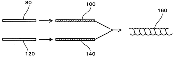
- FIG. 10 is a diagram for explaining an example of a twin yarn manufacturing method.
- a single strand 80 of A fiber is twisted to make a single twisted yarn 100 of A fiber.
- the single strand 120 of B fiber is twisted to make a single twist yarn 140 of B fiber.
- the single yarn 100 of these A fibers and the single yarn 140 of B fibers are aligned and twisted in the opposite direction to the twist of these single yarns 100, 140 to make a twin yarn 160.
- a woven fabric as a reinforcing base material is formed by weaving the above-mentioned twin yarn as warp (warp) and weft (weft).
- a plain woven fabric woven at a density of warp (warp) 36 to 44 / inch and weft (weft) 36 to 44 / inch is suitably used as the reinforcing base material.
- the fluororesin fibers and the PPS fibers are exposed at an almost equal area ratio on at least one surface serving as a sliding surface, so that the PTFE powder impregnated in the woven fabric is made of A sliding surface material having improved friction and wear characteristics combined with low friction can be obtained.
- the woven fabric as a reinforcing base material woven from the above-mentioned double yarn as warp and weft can be formed thick. This is because the sliding surface in the multilayer sliding member is integrally provided with a sliding surface material formed by impregnating the woven fabric with a specific resol type phenolic resin containing PTFE dispersed therein. Since it can process, the effect that the dimensional accuracy of the said multilayer sliding member can be made high is created.
- the amount of the reinforcing substrate contained in the sliding face material of the present invention is suitably 35 to 50% by mass. If the amount of the reinforcing substrate is less than 35% by mass, sufficient frictional wear characteristics will not be exhibited, and if it exceeds 50% by mass, the amount of the resol type phenolic resin described later will be reduced and the moldability will be significantly inhibited. There is a fear.
- the resol type phenol resin is synthesized by using phenols containing 50 to 100 mol% of bisphenol A and formaldehyde as amines as catalysts.
- this resol type phenol resin has a number average molecular weight Mn of 500 to 1000 by GPC measurement, and a dispersity Mw / Mn as a ratio of the weight average molecular weight Mw to the number average molecular weight Mn of 2.5 to 15.
- a dispersity Mw / Mn as a ratio of the weight average molecular weight Mw to the number average molecular weight Mn of 2.5 to 15.
- the resol type phenol resin used in the present invention preferably has a ratio of bisphenol A (C 15 H 16 O 2 ) of 50 to 100 mol% in phenols. This is the ratio of the number of moles of bisphenol A to the total number of moles of all phenols added at the start of synthesis.
- the synthesized resol type phenolic resin preferably has a number average molecular weight Mn of 500 to 1000 by GPC measurement and a molecular weight distribution dispersity Mw / Mn of 2.5 to 15.
- Mn number average molecular weight
- Mw / Mn molecular weight distribution dispersity
- the number average molecular weight Mn by GPC measurement is 500 to 1000 and the dispersity Mw / Mn is 2.5 to 15.
- the number average molecular weight Mn is less than 500, the mechanical strength is lowered even if the affinity with the reinforcing substrate is good, and when the number average molecular weight Mn exceeds 1000, the viscosity of the resol type phenol resin increases. Therefore, it becomes difficult to impregnate the reinforcing base material.
- the molar ratio of phenolic bisphenol A, the number average molecular weight Mn by GPC measurement, and the degree of dispersion Mw / Mn are within the above ranges, whereby Impregnation and adhesion can be ensured, and the mechanical strength of the sliding surface material can be ensured.
- phenols other than bisphenol A are included.
- examples of phenols other than bisphenol A include phenol, cresol, ethylphenol, aminophenol, resorcinol, xylenol, butylphenol, trimethylphenol, catechol, and phenylphenol.
- phenol is preferably used because of its characteristics.
- These phenols other than bisphenol A may be used alone, or two or more of them may be used as a mixture.
- Formaldehydes include formalin, paraformaldehyde, salicylaldehyde, benzaldehyde, p-hydroxybenzaldehyde and the like.
- formalin and paraformaldehyde are preferably used because of their ease of synthesis.
- These formaldehydes may be used alone or in combination of two or more.
- amines used as a catalyst include triethylamine, triethanolamine, benzyldimethylamine, and aqueous ammonia. Among them, triethylamine and aqueous ammonia are preferably used because of easy synthesis.
- the content of the resol type phenol resin contained in the sliding face material of the present invention is preferably 35 to 50% by mass.
- the content of the resol type phenol resin is less than 35% by mass, the moldability (manufacturing) of the sliding surface material is hindered, and when it exceeds 50% by mass, the mechanical strength of the sliding surface material is lowered.
- the PTFE powder blended in the resol type phenolic resin includes molding molding powder (hereinafter abbreviated as “high molecular weight PTFE”) and PTFE (hereinafter referred to as “high molecular weight PTFE”) having a molecular weight reduced by radiation irradiation or the like. Any of “low molecular weight PTFE”) may be used. Low molecular weight PTFE is mainly used as an additive material and is easy to grind and has good dispersibility.
- high molecular weight PTFE examples include “Teflon (registered trademark) 7-J”, “Teflon (registered trademark) 7A-J”, “Teflon (registered trademark) 70-J” manufactured by Mitsui DuPont Fluorochemical Co., Ltd.
- Examples include “Polyflon M-12 (trade name)” manufactured by Daikin Industries, Ltd., “Fluon G163 (trade name)”, “Fluon G190 (trade name)” manufactured by Asahi Glass Co., Ltd., and the like.
- low molecular weight PTFE examples include “TLP-10F (trade name)” manufactured by Mitsui DuPont Fluoro Chemical Co., Ltd. and “Lublon L-5 (trade name)” manufactured by Daikin Industries, Ltd. “Full-on L150J (product name)”, “Full-on L169J (product name)”, etc., “KTL-8N (product name)”, “KTL-2N (product name)” manufactured by Kitamura, and the like can be mentioned.
- both high molecular weight PTFE and low molecular weight PTFE can be used, but when mixed with the resol type phenol resin, in order to make it difficult to form a uniform dispersion and voids, a low molecular weight PTFE powder is used.
- the average particle size of the PTFE powder is 1 to 50 ⁇ m, preferably 1 to 30 ⁇ m, from the viewpoint of uniformly dispersing and preventing the formation of voids.
- the amount of PTFE contained in the sliding face material is suitably 10 to 30% by mass. If the amount of PTFE is less than 10% by weight, the effect of improving the friction and wear characteristics cannot be obtained. If it exceeds 30% by weight, the viscosity of the resin increases during molding, and voids may be generated. There is a risk that the adhesiveness of the resol type phenolic resin is lowered, the strength of the sliding face material or the multilayer sliding member is lowered, or delamination is caused.
- the sliding surface material of the present invention is a woven fabric as a reinforcing base material in which a double yarn comprising a single twisted yarn of a fluororesin fiber and a single twisted yarn of a PPS fiber is formed as a warp (warp) and a weft (weft). It consists of 35 to 50% by mass, PTFE 10 to 30% by mass and resol type phenolic resin 35 to 50% by mass, and a sliding surface material having good moldability, mechanical strength and frictional wear characteristics can be obtained.
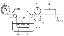
- FIG. 1 is a diagram schematically showing an example of a method for producing a prepreg (resin processing base material) of a sliding face material.
- a reinforcing base material made of a woven fabric formed by using a twisted yarn of a fluororesin fiber wound around an uncoiler 1 and a twisted yarn of a PPS fiber as a warp and a weft. 2 is fed to a container 5 storing a mixed solution 4 of PTFE powder and resol type phenolic resin varnish by a feed roller 3, and mixed in the container 5 by guide rollers 6 and 7 provided in the container 5.
- the liquid mixture 4 is applied to the surface of the reinforcing base 2.
- the reinforcing base material 2 coated with the mixed liquid 4 is sent to the compression rolls 9 and 10 by the feed roller 8, and the mixed liquid 4 coated on the surface of the reinforcing base material 2 by the compression rolls 9 and 10 is supplied. It is impregnated into the fiber structure gap.
- the solvent is blown off in the drying furnace 11 with respect to the reinforcing base material 2 impregnated and coated with the mixed solution 4, and at the same time, the reaction of the resol type phenolic resin varnish is advanced, and thereby a sliding surface that can be molded.
- a material prepreg (resin-processed substrate) 12 is produced.
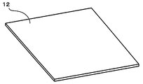
- FIG. 2 is a perspective view showing the prepreg 12 for the sliding face material cut into a square shape.
- the solid content of the resol type phenol resin prepared by dissolving the resol type phenol resin in the volatile solvent is about 30 to 65% by mass with respect to the whole resin varnish, and the viscosity of the resin varnish is preferably about 800 to 5000 cP. In particular, 1000 to 4000 cP is preferable.
- a multilayer sliding member 13 using the above-mentioned sliding surface material prepreg 12 will be described with reference to FIGS.
- the backing metal 14 of the multilayer sliding member 13 is produced by the same manufacturing method using the same manufacturing apparatus as the manufacturing apparatus shown in FIG. 1 used in the manufacturing method of the prepreg 12 of the sliding face material. That is, the woven fabric 15 made of organic fiber or inorganic fiber wound around the uncoiler 1 is sent to the container 5 storing the resol type phenolic resin varnish 16 by the feed roller 3, and the guide roller 6 provided in the container 5 and The resin varnish is applied to the surface of the woven fabric 15 by passing through the resol type phenolic resin varnish 16 stored in the container 5 by 7.
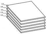
- FIG. 3 is a perspective view showing a plurality of prepregs 17 for the back metal 14 cut into a square shape.
- inorganic fiber woven fabric such as glass fiber woven fabric, carbon fiber woven fabric, or aramid resin fiber woven fabric (copolyparaphenylene 3,4'oxydiphenylene terephthalamide)
- organic fiber woven fabrics such as resin fiber woven fabrics are appropriately selected and used depending on the use of the multi-layer sliding member, for example, dry friction conditions, underwater friction conditions, boundary friction conditions, and the like.
- the number of prepregs 17 for the back metal 14 cut into a square shape capable of obtaining a desired flat plate area is prepared so as to obtain a desired finished thickness.
- at least one prepreg 12 for the sliding face material is prepared by cutting it into the same rectangular shape as the pre-plug 17 for the back metal 14.
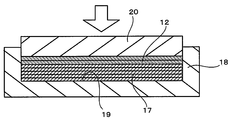
- a predetermined number of prepregs 17 for the back metal 14 are stacked in a rectangular recess 19 of the mold 18 of the heating and pressurizing apparatus, and then slide on the upper surface.
- the prepregs 12 for the face material are placed, and these are heated in a mold 18 to a temperature of 140 to 160 ° C., and are pressed in the laminating direction by a ram 20 at a pressure of 4.9 to 7 MPa, thereby forming a rectangular shape
- a multilayer molded product is obtained.
- the laminated prepreg 12 for the sliding face material and the prepreg 17 for the back metal 14 are joined to each other and fused.
- the obtained multilayer molded product is machined as shown in FIG. 5 to produce a flat multilayer sliding member 13.
- the flat multilayer sliding member 13 produced in this way is composed of a backing metal 14 made of a laminate of inorganic fiber woven fabric or organic fiber woven fabric, and a sliding surface integrally joined to one surface of the backing metal 14. And a sliding layer 21 made of a material prepreg 12.
- the sliding layer 21 made of the prepreg 12 for the sliding face material integrally joined onto the back metal 14 is excellent in frictional wear characteristics and has improved load resistance. Furthermore, since the swelling amount is extremely small even when used in a wet atmosphere such as oil or water, it can be applied to a wide range of applications such as dry friction conditions, boundary friction conditions, and water lubrication conditions.
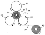
- ⁇ Cylindrical multilayer sliding member> 6 and 7 are diagrams schematically showing an example of a manufacturing method of a cylindrical multilayer sliding member in which the sliding face material is integrally joined to an inner peripheral surface (sliding face).
- the cylindrical multilayer sliding member can be produced by rolled forming using a rolled forming apparatus.
- a rolled forming apparatus shown in FIG. 6 normally, two heating rollers 22 and one pressure roller 23 are arranged so that each is located at the apex of a triangle, and a core mold 24 is placed in the middle thereof, and this core mold is arranged. 24, the prepreg 12 for the sliding surface material and the prepreg 17 for the back metal 14 are wound, and the core mold 24 is formed while being driven to rotate in a fixed direction.
- the three rollers 22, 22, and 23 This is a molding method for obtaining a cylindrical multilayer sliding member while heating and pressing.
- the prepreg 12 for the sliding face material cut to a predetermined width is wound around the outer peripheral surface of the core mold 24 heated to 120 to 200 ° C. in advance for at least one turn.
- the prepreg 17 for the back metal 14 is supplied to the outer peripheral surface of the back metal 14 through the heating rollers 22 and 22 heated to a temperature of 120 to 200 ° C., and pressurized by applying a pressure of 2 to 6 MPa. Rolling is performed by winding the roller 23 to a desired final thickness (outer diameter).
- the cylindrical multilayer molded body 26 thus molded is held in the core mold 24 and cured by heating in a heating furnace adjusted to an atmospheric temperature of 20 to 180 ° C., then cooled, and the core mold 24 is cooled. And a cylindrical multilayer molded body 26 is formed.
- the cylindrical multilayer molded body 26 thus manufactured is machined to form a cylindrical multilayer sliding member 27 having a desired dimension as shown in FIG.
- the cylindrical multilayer sliding member 27 formed in this way has a sliding layer 29 made of a sliding face material integrally joined to the inner peripheral surface of the cylindrical back metal 28.
- the inner peripheral surface of the sliding layer 29 functions as a sliding surface.
- the cylindrical multi-layer sliding member 27 has excellent friction and wear characteristics and improved load resistance, and further, the amount of swelling is extremely small even when used in a wet atmosphere such as in oil or water. It can be applied to a wide range of applications such as friction (dry) conditions, boundary friction conditions, and water lubrication conditions.
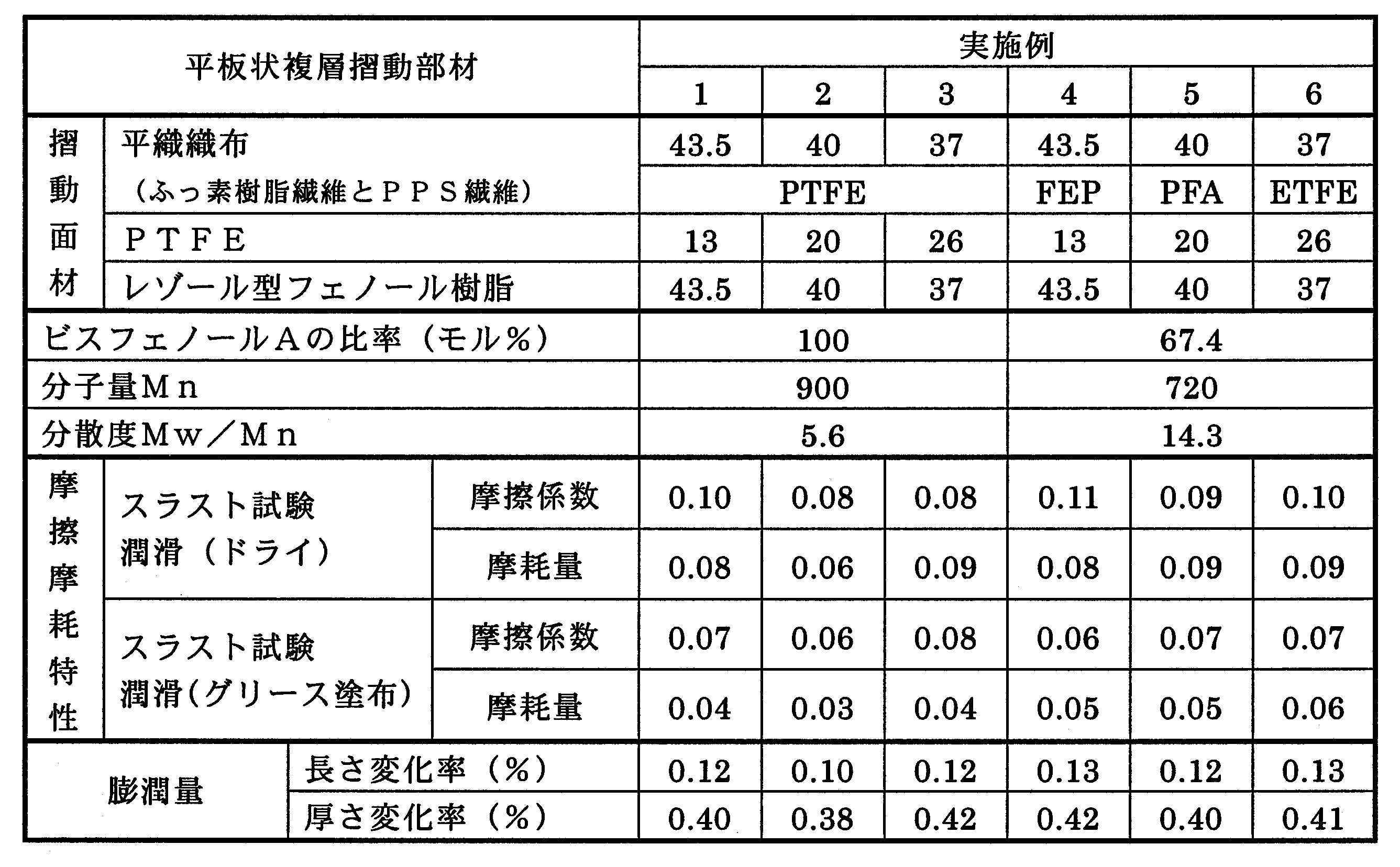
- a plain woven fabric is produced which is plain woven with a density of 40 warps per inch and 40 per inch wefts per inch. A material was used.
- or Example 3 the molar ratio of the bisphenol A in the used phenols is 100 mol%.
- the number average molecular weight Mn by GPC measurement of the obtained resol type phenol resin was 900, and dispersion degree Mw / Mn of molecular weight distribution was 5.6.
- Low molecular weight PTFE ("KTL-2N" (trade name) manufactured by Kitamura Co., Ltd.) is used as PTFE for the resol type phenolic resin varnish, and a predetermined amount of the low molecular weight PTFE powder is mixed and dispersed for each example. To prepare a mixed solution of the resol type phenolic resin varnish and the low molecular weight PTFE powder.
- a reinforcing base material 2 made of plain woven fabric wound around an uncoiler 1 is sent to a container 5 storing the mixed solution 4 by a feed roller 3, and is provided in the container 5.
- the liquid mixture 4 was applied to the surface of the reinforcing substrate 2 by passing through the liquid mixture 4 stored in the container 5 by the guide rollers 6 and 7.
- the reinforcing base material 2 coated with the mixed liquid 4 is sent to the compression rolls 9 and 10 by the feed roller 8, and the mixed liquid 4 coated on the surface of the reinforcing base material 2 by the compression rolls 9 and 10 is reinforced.
- the substrate was impregnated into the fiber structure gap.
- the reinforcing fiber woven fabric As the reinforcing fiber woven fabric, a single fiber (monofilament) having a diameter of 5 ⁇ m and a glass fiber single yarn composed of 100 bundles is used, and the number of warps (warp) is 65 / inch and weft (weft) ) Was plain woven at a density of 65 / inch to produce a glass fiber plain woven fabric, which was used as a reinforcing fiber woven fabric.
- the thermosetting synthetic resin the same resol type phenol resin (solid content 60 mass%) as described above was used.
- the resol type phenolic resin varnish 16 was applied to the surface of the reinforcing fiber woven fabric 15 by allowing the guide rollers 6 and 7 to pass through the resol type phenolic resin varnish 16 stored in the container 5. Subsequently, the reinforcing fiber woven fabric 15 coated with the resol type phenolic resin varnish 16 was fed to the compression rolls 9 and 10 by the feed roller 8 and applied to the surface of the reinforcing fiber woven fabric 15 by the compression rolls 9 and 10. The resol type phenolic resin varnish 16 was impregnated into the fiber structure gap of the reinforcing fiber woven fabric 15.
- the reinforcing fiber woven fabric 15 impregnated and coated with the resol type phenolic resin varnish 16 is fed into the drying furnace 11 and the reaction of the resol type phenolic resin varnish 16 is advanced at the same time as the solvent is blown off in the drying furnace 11.
- a moldable backing metal prepreg 17 made of 40% by mass of woven fabric and 60% by mass of a resol type phenolic resin was produced.
- the prepreg for the back metal was cut into a rectangular shape with a side length of 31 mm, and 10 sheets were stacked in the rectangular recess 19 of the mold 18 of the heating and pressing apparatus shown in FIG. .
- the prepregs for sliding face materials of Examples 1 to 3 were cut into squares each having a side length of 31 mm, and the prepregs for the back metal laminated in the recess 19 of the mold. 3 sheets are stacked on top of each other, heated in the mold 18 in the stacking direction at a temperature of 160 ° C. for 10 minutes, and pressure-molded at a pressure of 7 MPa to produce a rectangular multilayer molded body.
- the multilayer molded body 13 is machined to have a side of 30 mm and a thickness of 5 mm.
- the multilayer sliding member 13 is composed of a backing plate and a sliding layer 21 of a sliding face material integrally joined to the surface of the backing plate. Was made.
- Examples 4-6 (Reinforcing base material for sliding surface material)
- fluorine resin fibers FEP fibers (Example 4), PFA fibers (Example 5) and ETFE fibers (Example 6) are used, and 400 denier spun yarns are respectively twisted at 300 T / m (Z twist).
- a plain woven fabric is produced which is plain woven with a density of 40 warps per inch and 40 per inch wefts per inch. A material was used.
- a low molecular weight PTFE (same as in Example 1) is used as PTFE for the resol type phenol resin varnish, and a predetermined amount of the low molecular weight PTFE powder is blended and contained in each example, and the resol type phenol is contained.
- a mixed liquid of a resin varnish and a low molecular weight PTFE powder was prepared.
- the reinforcing base material 2 wound around the uncoiler 1 is sent to the container 5 storing the mixed solution 4 by the feed roller 3, and is provided in the container 5.
- the liquid mixture 4 was applied to the surface of the reinforcing substrate 2 by passing through the liquid mixture 4 stored in the container 5 by the guide rollers 6 and 7.
- the reinforcing base material 1 coated with the mixed liquid 4 is fed to the compression rolls 9 and 10 by the feed roller 8, and the mixed liquid 4 coated on the surface of the reinforcing base material 2 by the compression rolls 9 and 10 is used as the fiber.
- the tissue gap was impregnated.
- Example 4 Reinforcing substrate (plain woven fabric) 43.5% by mass, PTFE 13% by mass, resol type phenolic resin 43.5% by mass (Example 5) Reinforcing substrate (same as above) 40.0% by mass, PTFE 20% by mass, resol type phenolic resin 40% by mass (Example 6) Reinforcing substrate (same as above) 37.0% by mass, PTFE 26% by mass, resol type phenolic resin 37.0% by mass
- a moldable backing metal prepreg composed of 40% by mass of a reinforcing fiber woven fabric made of a glass fiber plain woven fabric as in Example 1 and 60% by mass of a resol type phenolic resin was used.
- Multi-layer sliding member In the same manner as in Example 1, a multi-layer sliding member having a side of 30 mm and a thickness of 5 mm and comprising a backing metal and a sliding layer for a sliding face material integrally joined to the surface of the backing metal is produced. did.
- Examples 7-9 As the prepreg for the sliding surface material, the same prepreg for the sliding surface material as in Examples 1 to 3 is used, and as the prepreg for the back metal, the same prepreg for back metal as in Example 1 is used. did. In the rolled forming apparatus shown in FIG. 6, the prepreg for the sliding face material, which is preheated to a temperature of 150 ° C. and cut to a length of 51 mm on the outer peripheral surface of the core mold 24 having an outer diameter of 60 mm, is provided for three rounds.
- a prepreg for backing metal is supplied to the outer peripheral surface of the winding roller 25 through a heating roller 22 heated to a temperature of 150 ° C., a pressure of 5 MPa is applied, and the pressure roller 23 is wound for 15 laps. It was attached and rolled.
- the cylindrical multilayer molded body 26 formed in this manner is held in the core mold 24, and is cured by heating in a heating furnace adjusted to an atmospheric temperature of 150 ° C. and then cooled, the core mold 24 is extracted, and the cylindrical shape is extracted.
- a multilayer molded body 26 was prepared.
- the cylindrical multilayer laminate 26 was machined to produce a cylindrical multilayer sliding member 27 as shown in FIG. 7 having dimensions of an inner diameter of 60 mm, an outer diameter of 75 mm, and a length of 50 mm.
- Examples 10-12 As the prepreg for the sliding surface material, the same prepreg for the sliding surface material as in Examples 4 to 6 is used, and as the prepreg for the back metal, the same prepreg for back metal as in Example 1 is used. did.
- a prepreg 12 for a sliding face material which is preliminarily heated to a temperature of 150 ° C. and cut into a length of 51 mm on the outer peripheral surface of the core mold 24 having an outer diameter of 60 mm, is rotated three times.
- the prepreg 17 for the back metal is supplied to the outer peripheral surface of the winding roller 25 through the heating roller 21 heated to a temperature of 150 ° C., and a pressure of 5 MPa is applied and the pressure roller 23 rotates 15 times. It was rolled and rolled.
- the cylindrical multilayer molded body 26 formed in this manner is held in the core mold 24, and is cured by heating in a heating furnace adjusted to an atmospheric temperature of 150 ° C. and then cooled, the core mold 24 is extracted, and the cylindrical shape is extracted.
- a multilayer molded body 26 was prepared.
- the cylindrical multilayer laminate 26 was machined to produce a cylindrical multilayer sliding member 27 having dimensions of an inner diameter of 60 mm, an outer diameter of 75 mm, and a length of 50 mm as shown in FIG.
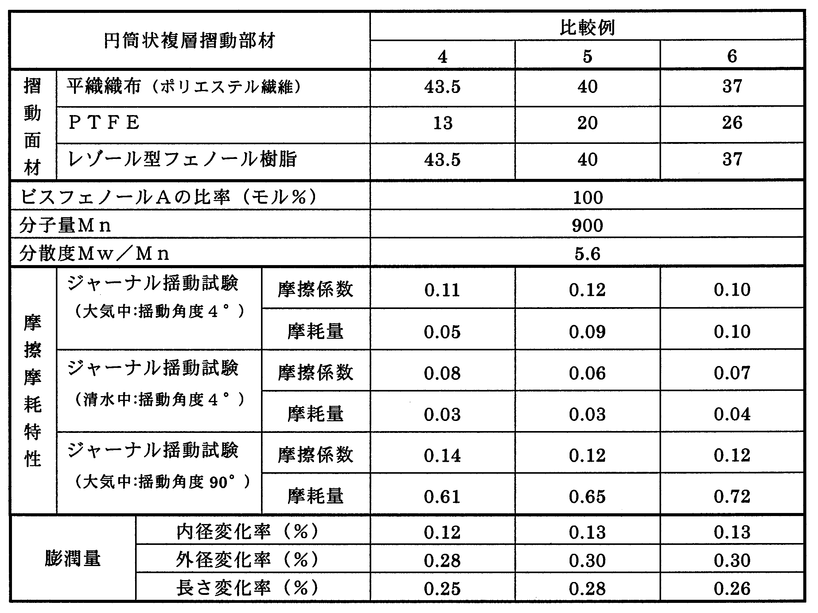
- Comparative Examples 1 to 3 (Prepreg for sliding surface material) A plain woven fabric in which warp yarns and 20 weft yarns of polyester fiber are used as a reinforcing base material, and a plain weave fabric with a density of 43 yarns / inch of warp yarns and 42 yarns / inch of weft yarns is printed. used.
- the sliding surface material of Comparative Examples 1 to 3 the resol type phenol resin dispersed and containing the same low molecular weight PTFE powder as in Examples 1 to 3 was used, and the same method as in Example 1 was used. A prepreg was prepared.
- the prepreg for the back metal is cut into a square shape with a side length of 31 mm, and 10 sheets are stacked in the rectangular recess 19 of the mold 18 of the heating and pressing apparatus shown in FIG. did.
- the prepreg for sliding face material of Comparative Examples 1 to 3 is cut into a rectangular shape with a side length of 31 mm, and the prepreg 17 for the back metal is laminated in the recess 19 of the mold. 3 layers are stacked on top of each other, heated in a mold 18 in the stacking direction at a temperature of 160 ° C. for 10 minutes, and pressure-molded at a pressure of 7 MPa to produce a rectangular multilayer molded body.
- a multi-layered sliding composed of a backing metal 14 and a sliding layer 21 of a sliding face material integrally joined to the surface of the backing metal 14 with a side length of 30 mm and a thickness of 5 mm. Member 13 was produced.
- Comparative Examples 4-6 Prepreg for sliding surface material
- Comparative Examples 1 to 3 The same prepreg for sliding face material as in Comparative Examples 1 to 3 was used.
- the prepreg 12 for the sliding surface material which is preliminarily heated to a temperature of 150 ° C. and cut into a length of 51 mm on the outer peripheral surface of the core mold having an outer diameter of 60 mm, is equivalent to three turns.
- a prepreg 16 for backing metal is supplied to the outer peripheral surface of the winding roller 25 through a heating roller 22 heated to a temperature of 150 ° C., a pressure of 5 MPa is applied, and the pressure roller 23 rotates 15 times. It was rolled and rolled.
- the cylindrical multilayer molded body 26 formed in this manner is held in the core mold 24, and is cured by heating in a heating furnace adjusted to an atmospheric temperature of 150 ° C. and then cooled, the core mold 24 is extracted, and the cylindrical shape is extracted.
- a multilayer molded body 26 was prepared.
- the cylindrical multilayer laminate 26 was machined to produce a cylindrical multilayer sliding member 27 having dimensions of an inner diameter of 60 mm, an outer diameter of 75 mm, and a length of 50 mm as shown in FIG.
- Friction and Wear Characteristics of Flat Multilayer Sliding Members of Examples 1 to 6 and Comparative Examples 1 to 3 (1) Thrust Test Friction coefficient and wear amount were measured under the test conditions shown in Table 1. About the amount of wear, it showed by the amount of dimensional change after 30 hours of test time.
- Friction and Wear Characteristics of Cylindrical Multilayer Sliding Members of Examples 7 to 12 and Comparative Examples 4 to 6 (1) Journal Swing Test Friction coefficient and wear amount were measured under the test conditions described in Tables 2 and 3. The amount of wear is indicated by the dimensional change after the end of the test time of 100 hours.
- Tables 4 to 6 show the test results of the friction and wear test.
- the number average molecular weight Mn and the degree of dispersion Mw / Mn of the resol type phenol resin were measured by GPC, and the numerical values were calculated from a calibration curve using a polystyrene standard substance.
- the measuring devices are as follows.
- GPC device HLC-8120 manufactured by Tosoh Corporation Column: Tosoh TSKgel G3000HXL [exclusion limit molecular weight (polystyrene conversion) 1 ⁇ 10 3 ], followed by one TSKgel G2000HXL [exclusion limit molecular weight (polystyrene conversion) 1 ⁇ 10 4 ] 2 detectors used: manufactured by Tosoh Corporation UV-8020
- the multilayer sliding members of Examples 7 to 12 are the same as those of Comparative Examples 4 to 6. It can be seen that the friction coefficient is lower than that of the conventional multilayer sliding member and the wear resistance is improved. In particular, in the test where the journal swing angle is 90 ° ( ⁇ 45 °), the multilayer sliding members of Examples 7 to 12 are more than the conventional multilayer sliding members of Comparative Examples 4 to 6. It can also be seen that the wear resistance is greatly improved. Moreover, about the amount of swelling, the multilayer sliding member of the Example and the multilayer sliding member of the comparative example showed substantially the same performance.
- various twisted yarns formed by aligning at least two pieces of fluorine resin fibers and PPS fibers that constitute the sliding surface material of the present invention and twisting them in the direction opposite to the direction of the single twisted yarn.
- the woven fabric as a reinforcing substrate formed as warps and wefts is impregnated in the woven fabric because the fluororesin fibers and the PPS fibers are exposed at an almost equal area ratio on at least one surface which becomes the sliding surface. Combined with the low friction property of PTFE powder, it improves the friction and wear characteristics.
- the multi-layer sliding member provided with this sliding face material on the sliding face has excellent friction and wear characteristics and rigidity. High and excellent in mechanical strength.
- this multilayer sliding member has a very small amount of swelling even when used in a humid atmosphere such as water, the dimensional change due to swelling is extremely small, and dry friction (dry) conditions, grease lubrication conditions, Furthermore, it can be applied to a wide range of applications such as water lubrication conditions.
Landscapes
- Engineering & Computer Science (AREA)
- General Engineering & Computer Science (AREA)
- Mechanical Engineering (AREA)
- Chemical & Material Sciences (AREA)
- Manufacturing & Machinery (AREA)
- Materials Engineering (AREA)
- Medicinal Chemistry (AREA)
- Polymers & Plastics (AREA)
- Organic Chemistry (AREA)
- Chemical Kinetics & Catalysis (AREA)
- Health & Medical Sciences (AREA)
- Sliding-Contact Bearings (AREA)
- Reinforced Plastic Materials (AREA)
Abstract
Description
図10は、双糸の製造方法の一例を説明するための図である。図10において、A繊維の単糸80に撚りを掛けてA繊維の片撚糸100を作る。これとは別に、B繊維の単糸120に撚りを掛けてB繊維の片撚糸140を作る。それらA繊維の片撚糸100とB繊維の片撚糸140とを揃え、それら片撚糸100,140の撚りと反対方向に撚りを掛けて双糸160を作ることができる。
図1は、摺動面材のプリプレグ(樹脂加工基材)の製造方法の一例を概略的に示した図である。図1に示す製造装置において、アンコイラ1に巻かれたふっ素樹脂繊維の片撚り糸とPPS繊維の片撚り糸からな双糸を経糸(たて糸)及び緯糸(よこ糸)として形成した織布からなる補強基材2は、送りローラ3によってPTFE粉末とレゾール型フェノール樹脂ワニスとの混合液4を貯えた容器5に送られ、容器5内に設けられた案内ローラ6及び7によって容器5内に貯えられた混合液4内を通過せしめられることにより、該補強基材2の表面に該混合液4が塗工される。ついで、混合液4が塗工された補強基材2は送りローラ8によって圧縮ロール9及び10に送られ、該圧縮ロール9及び10によって補強基材2の表面に塗工された混合液4が繊維組織隙間にまで含浸せしめられる。そして、該混合液4が含浸塗工された補強基材2に対して乾燥炉11内で溶剤が飛ばされると同時に該レゾール型フェノール樹脂ワニスの反応が進められ、これにより成形可能な摺動面材のプリプレグ(樹脂加工基材)12が作製される。図2は、方形状に切断した摺動面材用のプリプレグ12を示す斜視図である。
上記摺動面材のプリプレグ12を使用した複層摺動部材13を図3~図5に基づき説明する。複層摺動部材13の裏金14は、前記摺動面材のプリプレグ12の製造方法で使用した図1に示す製造装置と同様の製造装置によって同様の製造方法によって作製される。すなわち、アンコイラ1に巻かれた有機繊維又は無機繊維からなる織布15は、送りローラ3によってレゾール型フェノール樹脂ワニス16を貯えた容器5に送られ、容器5内に設けられた案内ローラ6及び7によって容器5内に貯えられたレゾール型フェノール樹脂ワニス16内を通過せしめられることにより、該織布15の表面に該樹脂ワニスが塗工される。ついで、樹脂ワニスが塗工された織布15は送りローラ8によって圧縮ロール9及び10に送られ、該圧縮ロール9及び10によって該樹脂ワニスが含浸塗工された織布15に対して乾燥炉11内で溶剤が飛ばされると同時に該樹脂ワニスの反応が進められ、これにより成形可能な裏金14のプリプレグ17が作製される。図3は、方形状に切断した複数枚の裏金14用のプリプレグ17を示す斜視図である。
図6及び図7は、前記摺動面材を内周面(摺動面)に一体的に接合した円筒状の複層摺動部材の製造方法の一例を概略的に示した図である。円筒状の複層摺動部材は、ロールド成形装置を用いたロールド成形により作製することができる。図6に示すロールド成形装置は、通常、2つの加熱ローラ22と1つの加圧ローラ23をそれぞれが三角形の頂点に位置するように配置し、その真ん中に芯型24を置いて、この芯型24に前記摺動面材用のプリプレグ12及び裏金14用のプリプレグ17を巻きつけ、該芯型24を一定方向に駆動回転させながら成形するもので、前記3本のローラ22、22及び23によって加熱、加圧しながら円筒状の複層摺動部材を得る成形方法である。
実施例1~3
(摺動面材用の補強基材)
ふっ素樹脂繊維としてPTFE繊維を使用し、400デニールの紡績糸を280T/mで下撚り(Z撚り)を掛けて形成した片撚り糸と、20綿番手のPPS繊維の紡績糸を280T/mで下撚り(Z撚り)を掛けて形成した片撚り糸を準備した。これら片撚り糸をそれぞれ1本ずつ2本引き揃え、該片撚り糸の片撚り方向(Z方向)と反対側(S方向)に275T/mで撚り(S撚り)を掛けて双糸を形成した。この双糸を経糸(たて糸)及び緯糸(よこ糸)として、経糸の打ち込み本数を40本/インチ、緯糸の打ち込み本数を40本/インチの密度で平織した平織織布を作製し、これを補強基材とした。
撹拌機、温度計及び冷却管を備えたセパラブルフラスコに、ビスフェノールA300gと37%ホルムアルデヒド水溶液192gを投入し、撹拌しながら25%アンモニア水溶液9gを投入したのち、常圧下で昇温し90℃の温度に到達後、2.5時間縮合反応させた。その後、0.015MPaの減圧下で80℃の温度まで昇温して水分の除去を行った。ついで、メタノール64gを添加して常圧下で85℃の温度まで昇温し、4時間縮合反応させて濃縮し、これを樹脂固形分60質量%となるようにメタノールで希釈してレゾール型フェノール樹脂(固形分60質量%のワニス)を作製した。実施例1ないし実施例3では、使用したフェノール類中のビスフェノールAのモル比率は、100モル%である。得られたレゾール型フェノール樹脂のGPC測定による数平均分子量Mnは900、分子量分布の分散度Mw/Mnは5.6であった。
図1に示した製造装置を使用し、アンコイラ1に巻かれた平織織布からなる補強基材2を送りローラ3によって前記混合液4を貯えた容器5に送り、容器5内に設けられた案内ローラ6及び7によって容器5内に貯えられた混合液4内を通過させることにより、補強基材2の表面に混合液4を塗工した。ついで、混合液4が塗工された補強基材2を送りローラ8によって圧縮ロール9及び10に送り、圧縮ロール9及び10によって補強基材2の表面に塗工された混合液4を該補強基材の繊維組織隙間にまで含浸させた。そして、混合液4が塗工された補強基材2を乾燥炉11に送り、溶剤を飛ばすと同時に該混合液4の反応を進め、実施例1ないし実施例3の摺動面材用のプリプレグを作製した。
(実施例1)補強基材(平織織布)43.5質量%、PTFE13質量%、レゾール型フェノール樹脂43.5質量%
(実施例2)補強基材(同上)40.0質量%、PTFE20質量%、レゾール型フェノール樹脂40質量%
(実施例3)補強基材(同上)37.0質量%、PTFE26質量%、レゾール型フェノール樹脂37.0質量%
補強繊維織布として、単繊維(モノフィラメント)の直径が5μmで、集束本数が100本で構成されたガラス繊維単糸を使用し、経糸(たて糸)の打ち込み本数を65本/インチ、緯糸(よこ糸)の打ち込み本数を65本/インチの密度で平織してガラス繊維平織織布を作製し、これを補強繊維織布とした。熱硬化性合成樹脂として、前記と同様のレゾール型フェノール樹脂(固形分60質量%)を使用した。図1に示す製造装置のアンコイラ1に巻かれた補強繊維織布(ガラス繊維平織織布)15を送りローラ3によってレゾール型フェノール樹脂ワニス16を貯えた容器5に送り、容器5内に設けられた案内ローラ6及び7によって容器5内に貯えられたレゾール型フェノール樹脂ワニス16内を通過せしめることにより、該補強繊維織布15の表面に該レゾール型フェノール樹脂ワニス16を塗工した。ついで、レゾール型フェノール樹脂ワニス16が塗工された補強繊維織布15を送りローラ8によって圧縮ロール9及び10に送り、該圧縮ロール9及び10によって補強繊維織布15の表面に塗工されたレゾール型フェノール樹脂ワニス16を該補強繊維織布15の繊維組織隙間にまで含浸させた。該レゾール型フェノール樹脂ワニス16を含浸塗工した補強繊維織布15を乾燥炉11内に送り、該乾燥炉11内で溶剤を飛ばすと同時に該レゾール型フェノール樹脂ワニス16の反応を進め、補強繊維織布40質量%、レゾール型フェノール樹脂60質量%からなる成形可能な裏金用のプリプレグ17を作製した。
前記裏金用のプリプレグを一辺の長さが31mmの方形状に切断し、これを前記図4に示す加熱加圧装置の金型18の方形状の凹所19内に10枚重ね合わせて積層した。一方、前記実施例1ないし実施例3の摺動面材用のプリプレグをそれぞれ一辺の長さが31mmの方形状に切断し、これを金型の凹所19内に積層された裏金用のプリプレグの上に3枚重ね合わせて積層したのち、金型18内で積層方向に160℃の温度で10分間加熱し、圧力7MPaで加圧成形して方形状の複層成形体を作製し、この複層成形体に機械加工を施して一辺が30mm、厚さが5mmであって、裏金と裏金の表面に一体的に接合された摺動面材の滑り層21からなる複層摺動部材13を作製した。
(摺動面材用の補強基材)
ふっ素樹脂繊維として、FEP繊維(実施例4)、PFA繊維(実施例5)及びETFE繊維(実施例6)を使用し、それぞれ400デニールの紡績糸を300T/mで下撚り(Z撚り)を掛けて形成した片撚り糸と、20綿番手のPPS繊維の紡績糸を300T/mで下撚り(Z撚り)を掛けて形成した片撚り糸を準備した。これら片撚り糸をそれぞれ1本ずつ2本引き揃え、該片撚り糸の片撚り方向(Z方向)と反対側(S方向)に295T/mで撚り(S撚り)を掛けて双糸を作製した。この双糸を経糸(たて糸)及び緯糸(よこ糸)として、経糸の打ち込み本数を40本/インチ、緯糸の打ち込み本数を40本/インチの密度で平織した平織織布を作製し、これを補強基材とした。
前記実施例1と同様のセパラブルフラスコに、ビスフェノールA160gと37%ホルムアルデヒド水溶液79gを投入し、撹拌しながらトリエチルアミン1.3gを投入したのち、常圧下で昇温し100℃の還流条件下で1時間縮合反応させた。その後一旦冷却し、フェノール32gと37%ホルムアルデヒド水溶液30gとトリエチルアミン0.3gとを投入した。ついで、常圧下で昇温し、100℃の還流条件下で2時間縮合反応を行ったのち、0.015MPaの減圧下で80℃の温度まで昇温して水分の除去を行った。ついで、メタノール24gを添加して常圧下で90℃の温度まで昇温し、4時間縮合反応させて濃縮し、これを樹脂固形分60質量%となるようにメタノールで希釈してレゾール型フェノール樹脂(固形分60質量%のワニス)を作製した。実施例4~6では、使用したフェノール類中のビスフェノールAのモル比率は、67.4モル%である。得られたレゾール型フェノール樹脂のGPC測定による数平均分子量Mnは720、分子量分布の分散度Mw/Mnは14.3であった。
前記実施例1と同様、図1に示す製造装置を使用し、アンコイラ1に巻かれた補強基材2を送りローラ3によって混合液4を貯えた容器5に送り、容器5内に設けられた案内ローラ6及び7によって容器5内に貯えられた混合液4内を通過させることにより、補強基材2の表面に混合液4を塗工した。ついで、混合液4が塗工された補強基材1を送りローラ8によって圧縮ロール9及び10に送り、圧縮ロール9及び10によって補強基材2の表面に塗工された混合液4を、繊維組織隙間にまで含浸させた。そして、混合液4が含浸塗工された補強基材2を乾燥炉11に送り、溶剤を飛ばすと同時に該混合液4の反応を進め、実施例4ないし実施例6の摺動面材用のプリプレグを作製した。
(実施例4)補強基材(平織織布)43.5質量%、PTFE13質量%、レゾール型フェノール樹脂43.5質量%
(実施例5)補強基材(同上)40.0質量%、PTFE20質量%、レゾール型フェノール樹脂40質量%
(実施例6)補強基材(同上)37.0質量%、PTFE26質量%、レゾール型フェノール樹脂37.0質量%
裏金は、前記実施例1と同様のガラス繊維平織織布からなる補強繊維織布40質量%とレゾール型フェノール樹脂60質量%からなる成形可能な裏金用のプリプレグを使用した。
前記実施例1と同様にして、一辺が30mm、厚さ5mmであって、裏金と該裏金の表面に一体的に接合した摺動面材用の滑り層とからなる複層摺動部材を作製した。
実施例7~9
摺動面材用のプリプレグとして、前記実施例1ないし実施例3と同様の摺動面材用のプリプレグを、また裏金用のプリプレグとして、前記実施例1と同様の裏金用のプリプレグをそれぞれ使用した。図6に示すロールド成形装置において、予め150℃の温度に加熱し、外径が60mmの芯型24の外周面に、幅51mmの長さに切断した摺動面材用のプリプレグを3周分巻きつけた後、その外周面に裏金用のプリプレグを巻きロール25より150℃の温度に加熱された加熱ローラ22を介して供給し、5MPaの圧力を掛けて加圧ローラ23で15周分巻きつけてロールド成形した。このようにして成形した円筒状の複層成形体26を芯型24に保持した状態で150℃の雰囲気温度に調整した加熱炉で加熱硬化させた後冷却し、芯型24を抜き取り、円筒状の複層成形体26を作製した。この円筒状の複層積層体26に機械加工を施し、内径60mm、外径75mm、長さ50mmの寸法を有する図7に示すような円筒状の複層摺動部材27を作製した。
摺動面材用のプリプレグとして、前記実施例4ないし実施例6と同様の摺動面材用のプリプレグを、また裏金用のプリプレグとして、前記実施例1と同様の裏金用のプリプレグをそれぞれ使用した。図6に示すロールド成形装置において、予め150℃の温度に加熱し、外径が60mmの芯型24の外周面に、幅51mmの長さに切断した摺動面材用のプリプレグ12を3周分巻きつけた後、その外周面に裏金用のプリプレグ17を巻きロール25より150℃の温度に加熱された加熱ローラ21を介して供給し、5MPaの圧力を掛けて加圧ローラ23で15周分巻きつけてロールド成形した。このようにして成形した円筒状の複層成形体26を芯型24に保持した状態で150℃の雰囲気温度に調整した加熱炉で加熱硬化させた後冷却し、芯型24を抜き取り、円筒状の複層成形体26を作製した。この円筒状の複層積層体26に機械加工を施し、図7に示すような内径60mm、外径75mm、長さ50mmの寸法を有する円筒状の複層摺動部材27を作製した。
比較例1~3
(摺動面材用のプリプレグ)
補強基材として、経糸及び緯糸を20綿番手のポリエステル繊維の紡績糸を使用し、経糸の打ち込み本数を43本/インチ、緯糸の打ち込み本数を42本/インチの密度で平織した平織織布を使用した。前記実施例1ないし実施例3と同様の低分子量PTFE粉末を分散含有したレゾール型フェノール樹脂を使用し、前記実施例1と同様の方法で、比較例1ないし比較例3の摺動面材用のプリプレグを作製した。
(比較例1)補強基材(平織織布)43.5質量%、PTFE13質量%、レゾール型フェノール樹脂43.5質量%
(比較例2)補強基材(同上)40.0質量%、PTFE20質量%、レゾール型フェノール樹脂40質量%
(比較例3)補強基材(同上)37.0質量%、PTFE26質量%、レゾール型フェノール樹脂37.0質量%
裏金用のプリプレグとして、前記実施例1と同様のガラス繊維平織織布からなる補強繊維織布40質量%とレゾール型フェノール樹脂60質量%からなる成形可能な裏金用のプリプレグを使用した。
前記裏金用のプリプレグを、一辺の長さが31mmの方形状に切断し、これを前記図4に示す加熱加圧装置の金型18の方形状の凹所19内に10枚重ね合わせて積層した。一方、前記比較例1ないし比較例3の摺動面材用のプリプレグをそれぞれ一辺の長さが31mmの方形状に切断し、これを金型の凹所19内に積層した裏金用のプリプレグ17の上に3枚重ね合わせて積層したのち、金型18内で積層方向に160℃の温度で10分間加熱し、圧力7MPaで加圧成形して方形状の複層成形体を作製し、これに機械加工を施して一辺の長さが30mm、厚さが5mmであって、裏金14と該裏金14の表面に一体的に接合した摺動面材の滑り層21とからなる複層摺動部材13を作製した。
比較例4~6
(摺動面材用のプリプレグ)
前記比較例1ないし比較例3と同様の摺動面材用のプリプレグを使用した。
裏金用のプリプレグとして、前記実施例1と同様のガラス繊維平織織布からなる補強繊維織布40質量%とレゾール型フェノール樹脂60質量%からなる成形可能な裏金用のプリプレグを使用した。
図6に示すロールド成形装置において、予め150℃の温度に加熱し、外径が60mmの芯型の外周面に、幅51mmの長さに切断した摺動面材用のプリプレグ12を3周分巻きつけた後24、その外周面に裏金用のプリプレグ16を巻きロール25より150℃の温度に加熱された加熱ローラ22を介して供給し、5MPaの圧力を掛けて加圧ローラ23で15周分巻きつけてロールド成形した。このようにして成形した円筒状の複層成形体26を芯型24に保持した状態で150℃の雰囲気温度に調整した加熱炉で加熱硬化させた後冷却し、芯型24を抜き取り、円筒状の複層成形体26を作製した。この円筒状の複層積層体26に機械加工を施し、図7に示すような内径60mm、外径75mm、長さ50mmの寸法を有する円筒状の複層摺動部材27を作製した。
(1)スラスト試験
表1に示す試験条件で摩擦係数及び摩耗量を測定した。摩耗量については、試験時間30時間終了後の寸法変化量で示した。

(1)ジャーナル揺動試験
表2及び表3に記載の試験条件で摩擦係数及び摩耗量を測定した。摩耗量については、試験時間100時間終了後の寸法変化量で示した。
GPC装置:東ソー社製HLC-8120
カラム:東ソー社製TSKgel G3000HXL〔排除限界分子量(ポリスチレン換算)1×10³〕1本に続けて、TSKgel G2000HXL〔排除限界分子量(ポリスチレン換算)1×10⁴〕2本使用
検出器:東ソー社製のUV-8020


12 摺動面材用のプリプレグ
13 平板状の複層摺動部材
14 裏金
17 裏金用のプリプレグ
21 滑り層
27 円筒状複層摺動部材
Claims (13)
- ふっ素樹脂繊維の片撚り糸とポリフェニレンサルファイド繊維の片撚り糸を少なくとも2本引き揃え、該片撚り糸の片撚り方向と反対側の撚りを掛けて形成した双糸を経糸及び緯糸として形成した織布からなる補強基材に、四ふっ化エチレン樹脂が分散含有されたレゾール型フェノール樹脂を含浸してなる摺動面材。
- ふっ素樹脂繊維は、ポリテトラフルオロエチレン繊維、テトラフルオロエチレン-パーフルオロアルキルビニルエーテル共重合体繊維、テトラフルオロエチレン-ヘキサフルオロプロピレン共重合体繊維及びエチレン-テトラフルオロエチレン共重合体繊維から選択される請求項1に記載の摺動面材。
- ふっ素樹脂繊維の片撚り糸は、少なくとも400デニールの糸である請求項1又は2に記載の摺動面材。
- ポリフェニレンサルファイド繊維の片撚り糸は、少なくとも20綿番手の糸である請求項1から3のいずれか一項に記載の摺動面材。
- 片撚り糸は、下撚り(Z撚り)糸である請求項1から4のいずれか一項に記載の摺動面材。
- 片撚り糸の撚り数は、260~300T/mである請求項1から5のいずれか一項に記載の摺動面材。
- 双糸の撚り数は、255~295T/mである請求項1から6のいずれか一項に記載の摺動面材。
- 補強基材は平織織布であり、該平織織布の密度は、経糸(たて糸)36~44本/インチ、緯糸(よこ糸)36~44本/インチである請求項1から7のいずれか一項に記載の摺動面材。
- レゾール型フェノール樹脂35~50質量%、四ふっ化エチレン樹脂10~30質量%及び補強基材35~50質量%含む請求項1から8のいずれか一項に記載の摺動面材。
- レゾール型フェノール樹脂は、ビスフェノールAを50~100モル%含むフェノール類とホルムアルデヒド類とをアミン類を触媒として合成され、ゲルパーミエーションクロマトグラフィー測定による数平均分子量Mnが500~1000でありかつ重量平均分子量Mwと数平均分子量Mnの比としての分散度Mw/Mnが2.5~15であるレゾール型フェノール樹脂ある請求項1から9のいずれか一項に記載の摺動面材。
- 四ふっ化エチレン樹脂は、高分子量四ふっ化エチレン樹脂又は低分子量四ふっ化エチレン樹脂のいずれかである請求項1から10のいずれか一項に記載の摺動面材。
- 全体形状が平板状でありかつ少なくとも摺動面において請求項1から11のいずれか一項に記載の摺動面材を備えた複層摺動部材。
- 全体形状が円筒状でありかつ少なくとも摺動面において請求項1から11のいずれか一項に記載の摺動面材を備えた複層摺動部材。
Priority Applications (5)
| Application Number | Priority Date | Filing Date | Title |
|---|---|---|---|
| EP10820043.7A EP2484713B1 (en) | 2009-09-30 | 2010-07-14 | Sliding surface material and multilayer sliding member equipped with said sliding surface material |
| US13/496,928 US10267361B2 (en) | 2009-09-30 | 2010-07-14 | Sliding contact surface-forming material, and multi-layered sliding contact component having the same |
| ES10820043.7T ES2609042T3 (es) | 2009-09-30 | 2010-07-14 | Material de superficie deslizante y elemento deslizante multicapa equipado con dicho material de superficie deslizante |
| CN201080043553.5A CN102549051B (zh) | 2009-09-30 | 2010-07-14 | 滑动面材料及具有该滑动面材料的多层滑动部件 |
| US16/050,586 US10767695B2 (en) | 2009-09-30 | 2018-07-31 | Sliding contact surface-forming material, slide bearing containing same, and method of using same in a moist environment |
Applications Claiming Priority (2)
| Application Number | Priority Date | Filing Date | Title |
|---|---|---|---|
| JP2009228606A JP5859183B2 (ja) | 2009-09-30 | 2009-09-30 | 摺動面材及び該摺動面材を備えた複層摺動部材 |
| JP2009-228606 | 2009-09-30 |
Related Child Applications (2)
| Application Number | Title | Priority Date | Filing Date |
|---|---|---|---|
| US13/496,928 A-371-Of-International US10267361B2 (en) | 2009-09-30 | 2010-07-14 | Sliding contact surface-forming material, and multi-layered sliding contact component having the same |
| US16/050,586 Division US10767695B2 (en) | 2009-09-30 | 2018-07-31 | Sliding contact surface-forming material, slide bearing containing same, and method of using same in a moist environment |
Publications (1)
| Publication Number | Publication Date |
|---|---|
| WO2011039917A1 true WO2011039917A1 (ja) | 2011-04-07 |
Family
ID=43825771
Family Applications (1)
| Application Number | Title | Priority Date | Filing Date |
|---|---|---|---|
| PCT/JP2010/004564 WO2011039917A1 (ja) | 2009-09-30 | 2010-07-14 | 摺動面材及び該摺動面材を備えた複層摺動部材 |
Country Status (6)
| Country | Link |
|---|---|
| US (2) | US10267361B2 (ja) |
| EP (1) | EP2484713B1 (ja) |
| JP (1) | JP5859183B2 (ja) |
| CN (1) | CN102549051B (ja) |
| ES (1) | ES2609042T3 (ja) |
| WO (1) | WO2011039917A1 (ja) |
Cited By (1)
| Publication number | Priority date | Publication date | Assignee | Title |
|---|---|---|---|---|
| CN103802405A (zh) * | 2013-12-30 | 2014-05-21 | 浙江国力科技有限公司 | 经纬线正反捻白坯浸胶同性布 |
Families Citing this family (10)
| Publication number | Priority date | Publication date | Assignee | Title |
|---|---|---|---|---|
| JP5595705B2 (ja) * | 2009-09-30 | 2014-09-24 | オイレス工業株式会社 | 摺動面材及び該摺動面材を備えた複層摺動部材 |
| JP6025434B2 (ja) * | 2012-07-19 | 2016-11-16 | オイレス工業株式会社 | 摺動部材 |
| JP6067307B2 (ja) * | 2012-10-01 | 2017-01-25 | オイレス工業株式会社 | 複層摺動部材の製造方法 |
| JP6143588B2 (ja) * | 2013-07-11 | 2017-06-07 | オイレス工業株式会社 | 積層すべり部材及びこの積層すべり部材を使用したすべり支承 |
| JP5521096B1 (ja) * | 2013-07-25 | 2014-06-11 | 新日鉄住金エンジニアリング株式会社 | 滑り免震装置 |
| BR112016001387B1 (pt) | 2013-07-25 | 2022-03-03 | Toray Industries, Inc | Tecido multicamadas resistente ao desgaste |
| US10307991B2 (en) | 2013-09-30 | 2019-06-04 | Saint-Gobain Performance Plastics Pampus Gmbh | Laminates with fluoropolymer cloth |
| DE102013223679A1 (de) * | 2013-11-20 | 2015-05-21 | Schaeffler Technologies AG & Co. KG | Verfahren zur Herstellung eines Gleitbelags |
| CN106435923A (zh) * | 2015-08-05 | 2017-02-22 | 东丽纤维研究所(中国)有限公司 | 一种自润滑织物及其生产方法和用途 |
| EP3750703A1 (en) * | 2019-06-13 | 2020-12-16 | Roller Bearing Company of America, Inc. | Machinable molded fretting buffer |
Citations (5)
| Publication number | Priority date | Publication date | Assignee | Title |
|---|---|---|---|---|
| JPH04225037A (ja) | 1990-04-03 | 1992-08-14 | Hoechst Ag | 繊維強化材料並びにその製造方法及びその用途 |
| JP2008293692A (ja) | 2007-05-22 | 2008-12-04 | Du Pont Toray Co Ltd | Led照明装置及び該装置を用いた車両用灯具 |
| JP2009091446A (ja) * | 2007-10-09 | 2009-04-30 | Oiles Ind Co Ltd | 摺動部材用繊維強化樹脂組成物及び積層摺動部材 |
| JP2009103193A (ja) * | 2007-10-23 | 2009-05-14 | Oiles Ind Co Ltd | 摺動面材及び摺動部材 |
| JP2010120992A (ja) * | 2008-11-17 | 2010-06-03 | Oiles Ind Co Ltd | 摺動部材用繊維強化樹脂組成物及び積層摺動部材 |
Family Cites Families (4)
| Publication number | Priority date | Publication date | Assignee | Title |
|---|---|---|---|---|
| US5880043A (en) * | 1991-04-03 | 1999-03-09 | Hoechst Aktiengesellschaft | Fiber-reinforced material and production and use thereof |
| EP0585874B1 (de) * | 1992-09-04 | 1997-03-12 | Hoechst Aktiengesellschaft | Mischgarn zur Herstellung der Gleitschicht von Gleitlagern aus faserverstärkten Thermoplasten |
| DE10159502C2 (de) * | 2001-12-04 | 2003-12-04 | Federal Mogul Deva Gmbh | Verbundgleitlager |
| JP5595705B2 (ja) * | 2009-09-30 | 2014-09-24 | オイレス工業株式会社 | 摺動面材及び該摺動面材を備えた複層摺動部材 |
-
2009
- 2009-09-30 JP JP2009228606A patent/JP5859183B2/ja active Active
-
2010
- 2010-07-14 CN CN201080043553.5A patent/CN102549051B/zh active Active
- 2010-07-14 ES ES10820043.7T patent/ES2609042T3/es active Active
- 2010-07-14 EP EP10820043.7A patent/EP2484713B1/en active Active
- 2010-07-14 WO PCT/JP2010/004564 patent/WO2011039917A1/ja active Application Filing
- 2010-07-14 US US13/496,928 patent/US10267361B2/en active Active
-
2018
- 2018-07-31 US US16/050,586 patent/US10767695B2/en active Active
Patent Citations (5)
| Publication number | Priority date | Publication date | Assignee | Title |
|---|---|---|---|---|
| JPH04225037A (ja) | 1990-04-03 | 1992-08-14 | Hoechst Ag | 繊維強化材料並びにその製造方法及びその用途 |
| JP2008293692A (ja) | 2007-05-22 | 2008-12-04 | Du Pont Toray Co Ltd | Led照明装置及び該装置を用いた車両用灯具 |
| JP2009091446A (ja) * | 2007-10-09 | 2009-04-30 | Oiles Ind Co Ltd | 摺動部材用繊維強化樹脂組成物及び積層摺動部材 |
| JP2009103193A (ja) * | 2007-10-23 | 2009-05-14 | Oiles Ind Co Ltd | 摺動面材及び摺動部材 |
| JP2010120992A (ja) * | 2008-11-17 | 2010-06-03 | Oiles Ind Co Ltd | 摺動部材用繊維強化樹脂組成物及び積層摺動部材 |
Non-Patent Citations (1)
| Title |
|---|
| See also references of EP2484713A4 * |
Cited By (1)
| Publication number | Priority date | Publication date | Assignee | Title |
|---|---|---|---|---|
| CN103802405A (zh) * | 2013-12-30 | 2014-05-21 | 浙江国力科技有限公司 | 经纬线正反捻白坯浸胶同性布 |
Also Published As
| Publication number | Publication date |
|---|---|
| CN102549051B (zh) | 2015-11-25 |
| ES2609042T3 (es) | 2017-04-18 |
| US10267361B2 (en) | 2019-04-23 |
| EP2484713A4 (en) | 2013-03-13 |
| EP2484713B1 (en) | 2016-09-28 |
| EP2484713A1 (en) | 2012-08-08 |
| US10767695B2 (en) | 2020-09-08 |
| CN102549051A (zh) | 2012-07-04 |
| US20180335081A1 (en) | 2018-11-22 |
| US20120178328A1 (en) | 2012-07-12 |
| JP2011075057A (ja) | 2011-04-14 |
| JP5859183B2 (ja) | 2016-02-10 |
Similar Documents
| Publication | Publication Date | Title |
|---|---|---|
| JP5859183B2 (ja) | 摺動面材及び該摺動面材を備えた複層摺動部材 | |
| JP5595705B2 (ja) | 摺動面材及び該摺動面材を備えた複層摺動部材 | |
| JP5249726B2 (ja) | 摺動部材用繊維強化樹脂組成物及び積層摺動部材 | |
| JP5026216B2 (ja) | 摺動部材用繊維強化樹脂組成物及び積層摺動部材 | |
| EP2623802A1 (en) | Retainer for rolling bearing, and rolling bearing | |
| JP6143588B2 (ja) | 積層すべり部材及びこの積層すべり部材を使用したすべり支承 | |
| JP6056859B2 (ja) | ヨー制御用ブレーキパッド及びブレーキ部材 | |
| JP5215630B2 (ja) | 摺動部材 | |
| JP4519355B2 (ja) | 水中用摺動部材ならびにその製造方法 | |
| EP2955399A1 (en) | Plain bearing | |
| JP4928410B2 (ja) | 複層摺動部材の製造方法 | |
| JP5026215B2 (ja) | 摺動部材用繊維強化樹脂組成物及び積層摺動部材 | |
| JP7165298B2 (ja) | 摺動用複合材料及びこれを備えた摺動部材 | |
| JP5216170B2 (ja) | 摺動部材 | |
| JP6610042B2 (ja) | 摺動部材及び風車のヨー制御用ブレーキ部材 | |
| JP2010196894A (ja) | 水中用摺動部材ならびにその製造方法 | |
| JP5582011B2 (ja) | 摺動面部材及びこれを用いた複層摺動部材 |
Legal Events
| Date | Code | Title | Description |
|---|---|---|---|
| WWE | Wipo information: entry into national phase |
Ref document number: 201080043553.5 Country of ref document: CN |
|
| 121 | Ep: the epo has been informed by wipo that ep was designated in this application |
Ref document number: 10820043 Country of ref document: EP Kind code of ref document: A1 |
|
| WWE | Wipo information: entry into national phase |
Ref document number: 2422/CHENP/2012 Country of ref document: IN |
|
| WWE | Wipo information: entry into national phase |
Ref document number: 13496928 Country of ref document: US |
|
| REEP | Request for entry into the european phase |
Ref document number: 2010820043 Country of ref document: EP |
|
| WWE | Wipo information: entry into national phase |
Ref document number: 2010820043 Country of ref document: EP |
|
| NENP | Non-entry into the national phase |
Ref country code: DE |