WO2011033793A1 - 超音波診断装置とそれを用いた診断方法 - Google Patents
超音波診断装置とそれを用いた診断方法 Download PDFInfo
- Publication number
- WO2011033793A1 WO2011033793A1 PCT/JP2010/005708 JP2010005708W WO2011033793A1 WO 2011033793 A1 WO2011033793 A1 WO 2011033793A1 JP 2010005708 W JP2010005708 W JP 2010005708W WO 2011033793 A1 WO2011033793 A1 WO 2011033793A1
- Authority
- WO
- WIPO (PCT)
- Prior art keywords
- probe
- image
- ultrasonic diagnostic
- diagnostic apparatus
- display
- Prior art date
Links
Images


Classifications
-
- A—HUMAN NECESSITIES
- A61—MEDICAL OR VETERINARY SCIENCE; HYGIENE
- A61B—DIAGNOSIS; SURGERY; IDENTIFICATION
- A61B8/00—Diagnosis using ultrasonic, sonic or infrasonic waves
- A61B8/42—Details of probe positioning or probe attachment to the patient
-
- A—HUMAN NECESSITIES
- A61—MEDICAL OR VETERINARY SCIENCE; HYGIENE
- A61B—DIAGNOSIS; SURGERY; IDENTIFICATION
- A61B8/00—Diagnosis using ultrasonic, sonic or infrasonic waves
- A61B8/06—Measuring blood flow
-
- A—HUMAN NECESSITIES
- A61—MEDICAL OR VETERINARY SCIENCE; HYGIENE
- A61B—DIAGNOSIS; SURGERY; IDENTIFICATION
- A61B8/00—Diagnosis using ultrasonic, sonic or infrasonic waves
- A61B8/08—Detecting organic movements or changes, e.g. tumours, cysts, swellings
- A61B8/0891—Detecting organic movements or changes, e.g. tumours, cysts, swellings for diagnosis of blood vessels
-
- A—HUMAN NECESSITIES
- A61—MEDICAL OR VETERINARY SCIENCE; HYGIENE
- A61B—DIAGNOSIS; SURGERY; IDENTIFICATION
- A61B8/00—Diagnosis using ultrasonic, sonic or infrasonic waves
- A61B8/42—Details of probe positioning or probe attachment to the patient
- A61B8/4245—Details of probe positioning or probe attachment to the patient involving determining the position of the probe, e.g. with respect to an external reference frame or to the patient
-
- A—HUMAN NECESSITIES
- A61—MEDICAL OR VETERINARY SCIENCE; HYGIENE
- A61B—DIAGNOSIS; SURGERY; IDENTIFICATION
- A61B8/00—Diagnosis using ultrasonic, sonic or infrasonic waves
- A61B8/42—Details of probe positioning or probe attachment to the patient
- A61B8/4272—Details of probe positioning or probe attachment to the patient involving the acoustic interface between the transducer and the tissue
- A61B8/4281—Details of probe positioning or probe attachment to the patient involving the acoustic interface between the transducer and the tissue characterised by sound-transmitting media or devices for coupling the transducer to the tissue
-
- A—HUMAN NECESSITIES
- A61—MEDICAL OR VETERINARY SCIENCE; HYGIENE
- A61B—DIAGNOSIS; SURGERY; IDENTIFICATION
- A61B8/00—Diagnosis using ultrasonic, sonic or infrasonic waves
- A61B8/46—Ultrasonic, sonic or infrasonic diagnostic devices with special arrangements for interfacing with the operator or the patient
- A61B8/461—Displaying means of special interest
- A61B8/463—Displaying means of special interest characterised by displaying multiple images or images and diagnostic data on one display
-
- A—HUMAN NECESSITIES
- A61—MEDICAL OR VETERINARY SCIENCE; HYGIENE
- A61B—DIAGNOSIS; SURGERY; IDENTIFICATION
- A61B8/00—Diagnosis using ultrasonic, sonic or infrasonic waves
- A61B8/46—Ultrasonic, sonic or infrasonic diagnostic devices with special arrangements for interfacing with the operator or the patient
- A61B8/461—Displaying means of special interest
- A61B8/464—Displaying means of special interest involving a plurality of displays
Definitions
- the present invention relates to an ultrasonic diagnostic apparatus and a diagnostic method using the same.
- an ultrasonic diagnostic apparatus has been in the limelight as a device for measuring the state of the carotid artery, and has the following structure.
- a conventional ultrasonic diagnostic apparatus includes a probe, a controller connected to the probe, and a display connected to the controller.
- a detection image of a detection target part (carotid artery) detected by a probe is displayed on a display (for example, see Non-Patent Document 1).
- the probe when measuring the state of the carotid artery, the probe must be applied at a position where the center line of the carotid artery can be cut in the longitudinal direction.
- the position and shape of the carotid artery varies from person to person, and the carotid artery is not visible from the surface of the body.
- the probe cannot be accurately applied to the position where the center line of the carotid artery can be cut longitudinally, and as a result, accurate measurement can be performed. It was difficult.
- An object of the present invention is to provide an ultrasonic diagnostic apparatus and diagnostic method capable of easily placing the probe on the center line of the carotid artery without being an expert, thereby enabling accurate measurement. There is.
- the ultrasonic diagnostic apparatus includes a controller to which a probe and a display are connected, and the controller is detected by the probe.
- the display device is configured to display a detection image of the target portion and a tilt position relationship image indicating a tilt position relationship of the probe with respect to the detection image by the detection target portion.
- FIG. 1 is an explanatory diagram showing an ultrasonic diagnostic apparatus according to Embodiment 1 of the present invention.
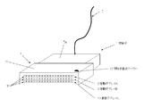
- FIG. 2 is a perspective view showing a probe of the ultrasonic diagnostic apparatus according to Embodiment 1 of the present invention.
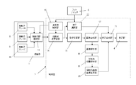
- FIG. 3 is a control block diagram of the ultrasonic diagnostic apparatus according to Embodiment 1 of the present invention.
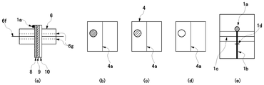
- 4A and 4B are explanatory views of a cross section of the carotid artery for explaining the operation.
- FIG. 4A is an explanatory view of a detection target part (A part) of the carotid artery.
- FIG. 4B is a cross section cut along a plane perpendicular to the center line of the carotid artery.
- FIG. 5 is a diagram for explaining the rotation operation of the probe from the carotid artery short-axis scan to the long-axis scan.
- FIG. 5A is an explanatory diagram showing the short-axis scan state perpendicular to the carotid artery.
- FIG. 6A and 6B are diagrams for explaining the rotation operation of the probe from the short-axis scan to the long-axis scan.
- FIG. 6A is a schematic diagram of the carotid artery.
- FIG. 6B is a schematic diagram of the probe.
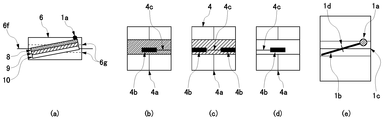
- FIG. 7 is a diagram for explaining the rotation operation of the probe from the carotid artery short axis scan to the long axis scan.
- FIG. 7A is an explanatory diagram for aligning the center in the longitudinal direction with the carotid artery.
- FIG. 8C is an explanatory diagram of an image of the transducer array 9.
- FIG. 8D is an explanatory diagram of an image of the transducer array 10.
- FIG. 8E is an explanatory diagram of a tilt positional relationship display image.
- FIG. 8A is a diagram for explaining the rotation operation of the probe from the carotid artery short-axis scan to the long-axis scan.
- FIG. 8A is an explanatory diagram showing a state in which the center in the longitudinal direction is shifted to the probe base point 1a side.
- (B) is an explanatory diagram of an image of the transducer array 8
- (c) is an explanatory diagram of an image of the transducer array 9
- (d) is an explanatory diagram of an image of the transducer array 10
- e is an inclination positional relationship Illustration of display image FIG.
- FIG. 9 is a diagram for explaining the rotation operation of the probe from the carotid artery short axis scan to the long axis scan.
- FIG. 9A shows the center of the longitudinal direction shifted in the direction opposite to the probe base point 1a side.
- (B) is an explanatory diagram of an image of the transducer array 8
- (c) is an explanatory diagram of an image of the transducer array 9
- (d) is an explanatory diagram of an image of the transducer array 10
- FIG. 10 is a diagram for explaining the rotation operation of the probe from the carotid artery short axis scan to the long axis scan.
- FIG. 10 is a diagram for explaining the rotation operation of the probe from the carotid artery short axis scan to the long axis scan.
- FIG. 10A is a diagram for explaining the positional relationship between the carotid artery 6 and the transducer array during the rotation.
- b) is an explanatory diagram of an image of the transducer array 8;
- (c) is an explanatory diagram of an image of the transducer array 9;
- (d) is an explanatory diagram of an image of the transducer array 10;
- Illustration of FIG. 11 is a diagram for explaining the rotation operation of the probe from the carotid artery short-axis scan to the long-axis scan.
- FIG. 11A is a diagram for explaining the positional relationship between the carotid artery 6 and the transducer array just before the end of the rotation.
- FIG. 12 is a diagram for explaining the rotation operation of the probe from the carotid artery short axis scan to the long axis scan.
- FIG. 12A shows the position when the carotid artery 6 and the long axis of the transducer array 9 coincide with each other.
- FIG. 13 is a diagram for explaining the operation of the rotation of the probe from the short-axis scan to the long-axis scan.
- FIG. 13A is an explanatory diagram of the positional relationship when the probe is rotated excessively.
- FIG. 14 is a diagram (a) for explaining the rotation operation of the probe from the carotid artery short axis scan to the long axis scan.
- Positional explanatory diagram (b) is an explanatory diagram of an image of the transducer array 8 (c) is an explanatory diagram of an image of the transducer array 9 (d) is an explanatory diagram of an image of the transducer array 10 (e) is , Explanatory diagram of tilt position relationship image
- FIG. 15 is a block diagram of (Embodiment 2) of the present invention.
- FIG. 16 is a block diagram of (Embodiment 3) of the present invention.
- the present invention includes a controller to which a probe and a display are connected, and the controller detects a detection image of a detection target portion detected by the probe and a probe for the detection image by the detection target portion.
- the tilt position relationship image showing the tilt position relationship is displayed on the display, thereby achieving the main purpose.
- the present invention includes a controller to which a probe and a display are connected, and the controller includes a detection image of a detection target portion detected by the probe, and a detection image by the detection target portion. Since the tilt position relationship image showing the tilt position relationship of the probe with respect to is configured to be displayed on the display, accurate measurement can be performed even by a non-expert.
- the controller displays the detection image of the detection target portion detected by the probe and the tilt positional relationship image indicating the tilt positional relationship of the probe with respect to the detection target portion on the display. Since the display can be displayed, the probe can be placed in an appropriate state with respect to the detection target portion while observing the image display of this display device. You can do it.
- FIG. 1 is a diagram showing an ultrasonic diagnostic apparatus according to Embodiment 1 of the present invention.
- the ultrasonic diagnostic apparatus according to the present embodiment includes a probe 1, a controller 3 to which the probe 1 is connected via a cable line 2, a display 4 connected to the controller 3, And a foot switch 5.
- the controller 3 generates a detection image of the carotid artery 6 (an example of a detection target portion of the subject) detected by the probe 1 and an inclination position relationship image indicating the inclination position relationship of the probe 1 with respect to the carotid artery 6.
- the display 4 is configured to display.
- the probe 1 has a plurality of (for example, three) transducer arrays 8 to 10 arranged in parallel on the distal end side of the main body case 7 (the contact portion side with the subject). It is the composition arranged in.
- the probe 1 is provided with a small-diameter gripping portion 7 a at the cable wire 2 side portion of the main body case 7. Further, the probe 1 is provided with a large-diameter and horizontally long contact portion 7b on the opposite side to the cable wire 2.
- a plurality of transducer arrays 8 to 10 are provided in an extended state in the longitudinal direction on the distal end surface (contact surface) side of the contact portion 7b. . In this extended state, the transducer arrays 8 to 10 are in parallel with a predetermined interval.
- Each of these transducer arrays 8 to 10 has a configuration in which a plurality of ultrasonic transducers 11 are linearly arranged. As is well known, each of these transducer arrays 8 to 10 is configured to change a focal position and obtain a wide range of detection images by sequentially driving a plurality of ultrasonic transducers 11 while switching them. .
- the probe 1 is provided with a probe base point marker 12 on one end side of the transducer arrays 8 to 10 on the upper surface of the contact portion 7b of the main body case 7. Yes. As will be described later, the position of the probe 1 is adjusted while referring to the position of the probe base point marker 12.
- FIG. 3 shows an electrical block diagram of the ultrasonic diagnostic apparatus. As shown in FIG. 3, a transducer group selector 13 is connected to the transducer arrays 8 to 10 of the probe 1.
- the electrical signal sent from the ultrasonic transmission / reception unit 14 of the controller 3 is driven by the transducer group selection unit 13 while sequentially switching the plurality of ultrasonic transducers 11 for each transducer array 8 to 10.
- ultrasonic waves are irradiated from the ultrasonic transducers 11 of the transducer arrays 8 to 10 to which the electric signal is applied toward the carotid artery 6 portion.
- the reflected waves from the carotid artery 6 are received by the plurality of ultrasonic transducers 11 that have been irradiated with ultrasonic waves, and are converted into electric signals by the plurality of ultrasonic transducers 11.
- this electrical signal is transmitted to the ultrasonic transmission / reception unit 14 via the transducer group selection unit 13.
- This series of control is performed by the transmission / reception control unit 15.
- the signal transmitted to the ultrasonic transmission / reception unit 14 is then processed by the signal processing unit 16. Thereafter, the image generation unit 17 generates an image signal.
- the image signal generated by the image generating unit 17 is then sequentially processed by the image unfolding unit 18, the counter object position unfolding unit 19, and the probe guidance image generating unit 20, and then transmitted to the display combining unit 21.
- the display composition unit 21 is supplied with the image signal generated by the image generation unit 17. Accordingly, as described later, the probe guidance image generated by the probe guidance image generation unit 20 is superimposed on the image signal generated by the image generation unit 17.
- the display composition unit 21 is also supplied with data calculated by the IMT calculation unit 22. Therefore, this data is also superimposed on the image signal generated by the image generation unit 17 as video information.
- FIG. 4A is a diagram showing a carotid artery 6 (detection target part (A part)) portion of a human body (subject) 23.
- the display 4 displays any one of FIGS. 4D to 4F.
- 4D to 4F are detection images in a state in which the carotid artery 6 is cut in a longitudinal direction along a plane including the center line thereof.
- FIG. 4D is an image in a state where no abnormality is recognized
- FIG. 4E is an image in a state of caution
- FIG. 4F is an image in an abnormal state.
- the carotid artery 6 has an endothelial cell 6a, an intima 6b, and an intima 6c from the inside to the outside.
- the outer membrane 6d As shown in FIG. 4 (b), the carotid artery 6 has an endothelial cell 6a, an intima 6b, and an intima 6c from the inside to the outside.
- the outer membrane 6d As shown in FIG. 4 (b), the carotid artery 6 has an endothelial cell 6a, an intima 6b, and an intima 6c from the inside to the outside.
- the outer membrane 6d The outer membrane 6d.
- FIG. 4B In the state of FIG. 4B, since the endothelial cells 6a, the inner membrane 6b, and the media 6c do not protrude toward the blood flow portion 6e, the opening area of the blood flow portion 6e is large. Therefore, the state of FIG. 4B is a normal state in which no abnormality is recognized. On the other hand, in the state of FIG. 4 (c), since plaque (B portion) is formed, the endothelial cells 6a, the intima 6b, and the media 6c protrude toward the blood flow part 6e. The opening area of the portion 6e is narrow. Therefore, FIG. 4C shows an abnormal state.
- FIG. 4D shows an image in which no abnormality is observed.
- the data calculated by the IMT calculation unit 22 in FIG. 3 is displayed as 0.6 mm as an example in FIG. 4D.
- FIG. 4E 1.3 mm is displayed.
- FIG. 4 (f) a plaque is generated and a state far exceeding it is displayed.
- FIG. 4D and 1.3 mm in FIG. 4E are called IMT values (thickness of the inner film 6b and the inner film 6c added). Since the IMT value of 1.1 mm or more is defined as an abnormal state (according to the criteria of the Japanese Society of Neurosonology), as described above, FIG. 4D shows a state where no abnormality is observed, FIG. FIG. 4E shows a state requiring attention, and FIG. 4F shows an abnormal state.
- the orientation of the probe 1 is set so that the longitudinal direction of the transducer arrays 8 to 10 (see FIG. 2) is substantially perpendicular to the neck muscle 23 (carotid artery 6). And press against the neck 23.
- the probe 1 is scanning the carotid artery 6 with a short axis.
- FIG. 5C the longitudinal direction of the carotid artery 6 and the longitudinal direction of the transducer arrays 8 to 10 are aligned, and formally, the probe 1 rotates from the short axis with respect to the carotid artery 6. Scan in the long axis state. As a result, detection images as shown in FIGS. 4D to 4F are obtained by cutting the carotid artery 6 in the longitudinal direction.
- the display 4 displays the tilt positional relationship image of the probe 1 generated by the probe guidance image generation unit 20, even if not an expert, based on this display, the probe is displayed. 1 can be adjusted to the appropriate position of the carotid artery 6.
- FIG. 6A schematically shows the carotid artery 6.
- 6d is the outer membrane
- 6f is the central axis of the carotid artery 6
- 6g is a detectable line indicating the detection range on both sides of the central axis 6f.
- FIG. 6B is a schematic diagram of the probe 1. As shown in FIG. 6B, a probe base point 1a is provided on one end side of the transducer arrays 8-10. The probe base point 1 a is provided on the same side as the probe base point marker 12 (see FIG. 2) of the main body case 7 constituting the probe 1.
- FIGS. 7 to 9 are diagrams showing display contents corresponding to the operation of FIG. 5 (a). That is, in FIGS. 7 to 9, the probe 1 is pressed against the neck muscle 23 in a state where the longitudinal direction of the transducer arrays 8 to 10 (see FIG. 2) is substantially perpendicular to the carotid artery 6. The display content of the display 4 is shown.
- FIG. 7A is an explanatory diagram when the longitudinal centers of the transducer arrays 8 to 10 are in a state perpendicular to the carotid artery 6 as in the operation of FIG. 5A.
- the horizontally cut image of the carotid artery 6 that can be seen is located on the center line 4a.
- the probe symbol 1b is orthogonal to the carotid artery centerline symbol 1c, and the midpoint 1d of the probe symbol 1b is the carotid artery centerline symbol 1c. It is in a state of overlapping.
- FIG. 7 (c) and FIG. 7 (e) what is displayed on the display 4 is the images of FIG. 7 (c) and FIG. 7 (e). Specifically, the image of FIG. 7C is displayed large on the display 4, and the tilt positional relationship image shown in FIG. 7E is displayed small in a part of the image.
- FIG. 7E is generated based on the images of FIGS. 7B to 7D. That is, the images of FIG. 7B and FIG. 7D together with the image of FIG. 7C, the probe 1 with respect to the carotid artery 6 from the position, size, shape, etc. of these three images.
- the state of the transducer arrays 8 to 10 is analyzed by the image folding unit 18 and the counter object position folding unit 19, and the probe guidance image generation unit 20 shows the state shown in FIG.
- a tilt positional relationship image is generated.
- the tilt position relationship image generated in this way is displayed on the display 4.
- the tilt positional relationship image shown in FIG. 7 (e) becomes the guidance screen (operation navigation information screen) of the probe 1. That is, the operator rotates / moves the probe 1 by looking at the image shown in FIG.
- the longitudinal centers of the transducer arrays 8 to 10 positions indicated by the center line symbol 1c: hereinafter referred to as 1c are substituted.
- the state perpendicular to the carotid artery 6 is established.
- the horizontally cut image of the carotid artery 6 that is visible is located on the center line 4a.
- FIG. 8 shows that the longitudinal direction of the probe 1 (the transducer arrays 8 to 10) is orthogonal to the carotid artery 6, but the probe 1 (the transducer arrays 8 to 10). 10) the center 1c in the longitudinal direction is shifted toward the probe base point 1a (the probe base point marker 12 of the body case 7) in the longitudinal direction of the probe 1 (the transducer arrays 8 to 10). Show.
- FIG. 9 shows that the longitudinal direction of the probe 1 is orthogonal to the carotid artery 6, but the longitudinal center of the probe 1 (the transducer arrays 8 to 10) is the probe. This shows a state where the probe 1 is shifted to the opposite side of the probe base point 1a of the child 1 (the probe base point marker 12 of the main body case 7).
- the images of FIGS. 7C, 7E, 8C, 8E, 9C, and 9E are displayed as probe guidance images. 4 is displayed.
- the probe 1 is moved in the horizontal direction along the neck muscle 23 so that the midpoint 1d of the probe symbol 1b overlaps the carotid artery centerline symbol 1c.
- the probe 1 is rotated in a direction matching the longitudinal direction of the carotid artery 6 as shown in FIG.
- the detected image of the carotid artery 6 is an ellipse as shown in FIGS. 10B to 10D. It becomes a shape. In this case, only the image of FIG. 10C is displayed on the display 4 among the images of FIGS. 10B to 10D.
- the operation navigation information screen (tilt position-related image) is in a state in which the probe symbol 1b is tilted with respect to the carotid artery centerline symbol 1c as shown in FIG.
- the image of FIG. 10E is generated based on the images of FIGS. 10B to 10D. That is, in what state the transducer arrays 8 to 10 of the probe 1 are in relation to the carotid artery 6 from the position, size, shape, and the like of the three images in FIG. 10B to FIG.
- the image unfolding unit 18 and the countermeasure object position unfolding unit 19 analyze whether or not there is, and the probe guidance image generation unit 20 generates the tilt position relationship image shown in FIG.
- the tilt position relationship image generated in this way is displayed on the display 4.
- the midpoint 1d of the probe symbol 1b intersects the carotid artery centerline symbol 1c, but the probe symbol 1b is greatly inclined with respect to the carotid artery centerline symbol 1c. Therefore, the probe 1 is moved along the neck 23 in the vertical direction.
- the tilt positional relationship image shown in FIG. 10 (e) becomes the guidance screen of the probe 1. That is, the operator turns the probe 1 by looking at the image shown in FIG. However, even during this rotation, the midpoint 1d of the probe symbol 1b intersects the carotid artery centerline symbol 1c.
- the probe symbol 1b Corrective operation is performed so that the midpoint 1d intersects the carotid artery centerline symbol 1c.
- the position of the probe base point 1a (the probe base point marker 12 of the main body case 7) in the image of the display 4 is used as a reference, and the midpoint 1d of the probe symbol 1b is used as a clue. Return to the intersection with the carotid artery centerline symbol 1c. Then, the probe 1 is rotated again from FIG. 5B to FIG. 5C.
- FIG. 11 is a diagram showing a state before the final state in which the probe 1 is rotated from FIG. 5 (b) to FIG. 5 (c). In this state, as shown in FIG. 11A, the probe symbol 1b is closer to the horizontal direction than in FIG.
- FIG. 11C the band-like carotid artery 6 starts to appear, but in FIGS. 11B to 11D, the unclear portion 4b and the clear portion 4c still clearer than the unclear portion 4b are present. Therefore, based on the unclear portion 4b information shown in FIGS. 11B to 11D, the tilt positional relationship image shown in FIG. 11E is created.
- FIG. 12 is a diagram showing a state in which the probe 1 is adjusted to a position where the central axis of the carotid artery 6 can be cut in the vertical direction.
- the probe symbol 1b overlaps the carotid artery centerline symbol 1c. 12 (e)
- the tilt position relationship image shows that the band-like carotid artery 6 appears clearly in FIG. 12 (c) and there is no unclear portion 4b
- FIGS. 12 (b) and 12 (d) show. Is created based on the presence of the unclear portion 4b.
- FIG. 13 is a view showing a state in which the probe 1 has passed through a position where the central axis of the carotid artery 6 can be cut in the longitudinal direction and has been further rotated.
- the probe symbol 1b is inclined to the opposite side to FIG. 11E with respect to the carotid artery centerline symbol 1c.
- 13 (e) shows that the band-like carotid artery 6 appears in FIG. 13 (c), and the blurred portion 4b exists in FIGS. 13 (b) to 13 (d).
- 11 is also taken into consideration), such as the fact that the position of the probe base point 1a is different.
- FIG. 14 shows a state in which the probe 1 has passed in the horizontal direction from a position where the central axis of the carotid artery 6 can be cut in the vertical direction (FIG. 5C). It is a figure which shows the state which has shifted
- the probe 1 is placed on the basis of the tilt positional relationship images (images shown in FIGS. 7 (e) to 14 (e)) displayed on the display 4.
- the movement can be easily adjusted to an appropriate part of the carotid artery 6, and the operability is extremely good.
- the detection image of the carotid artery 6 is obtained by a plurality of transducer arrays 8 to 10 as shown in FIG. 2.
- one transducer array 9 is used as the probe 1, one transducer array 9 is used. (Refer to FIG. 15) may be moved (oscillated) from the center to the left and right to thereby have a structure in which three transducer arrays 8 to 10 exist in a pseudo manner as in FIG.
- the display of FIGS. 7 to 14 can be obtained from the image of the center position and the image of the position moved to both sides from the center, and this also allows the probe 1 to be properly connected to the carotid artery 6.
- the movement can be easily adjusted to the portion, and the operability is extremely good.
- FIG. 15 is an electrical block diagram of the ultrasonic diagnostic apparatus of the present embodiment.
- the transducer array is provided with a drive unit 24 that swings the transducer array, and the drive unit 24 is controlled by the swing control unit 25.
- the left and right movement ranges of the transducer array 9 may be changed according to the result of analysis by the countermeasure object position analysis unit 19. As a result, it is possible to increase the amount of displacement of the carotid artery 6 as shown in FIG. 10, and as a result, it is possible to improve the analysis accuracy of the countermeasure object position analysis unit 19.
- the detection image of the carotid artery 6, the probe 1, the carotid artery 6, and the like are displayed on the single display unit 4 using the display combining unit 21.
- the tilt position relationship image showing the tilt position relationship is simultaneously displayed.
- the display unit 4 is changed to a plurality of configurations (display units 41 and 42), and the carotid artery 6 is displayed on each display unit.
- FIG. 16 is an electrical block diagram of the ultrasonic diagnostic apparatus of the present embodiment.
- a display synthesis selection unit 26 is provided instead of the display synthesis unit 21, and display control of a plurality of (two in this embodiment) display units 41 and 42 is performed. Yes.
- the display composition selection unit 26 displays only the detected image of the carotid artery 6 on the display units 41 and 42, or displays only the tilt position relationship image indicating the tilt position relationship between the probe 1 and the carotid artery 6.
- simultaneous display of a detection image of the carotid artery 6 and an inclination position relationship image indicating the inclination position relationship between the probe 1 and the carotid artery 6 is controlled by an arbitrary combination of the display unit and the image and displayed. be able to.
- the display unit installed in the ultrasonic diagnostic apparatus main body is referred to as a display unit 41, and the display unit installed separately from the display unit installed in the ultrasonic diagnostic apparatus main body is described as a display 42.
- the display unit 42 can take a configuration in the vicinity of the probe 1 or built in the probe 1. Therefore, when searching for the center position of the carotid artery 6 using the probe 1, the probe 1 can be operated while viewing the tilt positional relationship image displayed on the display unit 42. On the other hand, it is possible to reduce the forced posture and the movement of the line of sight as much as possible, and the operability is extremely good.
- the present invention includes a controller to which a probe and a display are connected, and the controller is configured to detect a detection image of a detection target portion detected by the probe and a detection image by the detection target portion. Since the tilt position relationship image showing the tilt position relationship of the probe is configured to be displayed on the display, accurate measurement can be performed even by a non-expert. That is, in the present invention, the controller displays the detection image of the detection target portion detected by the probe and the tilt positional relationship image indicating the tilt positional relationship of the probe with respect to the detection target portion on the display. Since the display can be displayed, the probe can be placed in an appropriate state with respect to the detection target portion while observing the image display of this display device. You can do it.
- the ultrasonic diagnostic apparatus of the present invention is expected to be widely used for, for example, examination of the carotid artery.
Landscapes
- Health & Medical Sciences (AREA)
- Life Sciences & Earth Sciences (AREA)
- Physics & Mathematics (AREA)
- Medical Informatics (AREA)
- Surgery (AREA)
- Pathology (AREA)
- Radiology & Medical Imaging (AREA)
- Engineering & Computer Science (AREA)
- Biomedical Technology (AREA)
- Heart & Thoracic Surgery (AREA)
- Biophysics (AREA)
- Molecular Biology (AREA)
- Nuclear Medicine, Radiotherapy & Molecular Imaging (AREA)
- Animal Behavior & Ethology (AREA)
- General Health & Medical Sciences (AREA)
- Public Health (AREA)
- Veterinary Medicine (AREA)
- Hematology (AREA)
- Acoustics & Sound (AREA)
- Vascular Medicine (AREA)
- Ultra Sonic Daignosis Equipment (AREA)
Priority Applications (4)
| Application Number | Priority Date | Filing Date | Title |
|---|---|---|---|
| US13/496,579 US8942453B2 (en) | 2009-09-18 | 2010-09-21 | Ultrasonograph and method of diagnosis using same |
| JP2011507479A JPWO2011033793A1 (ja) | 2009-09-18 | 2010-09-21 | 超音波診断装置とそれを用いた診断方法 |
| CN2010800436913A CN102573646A (zh) | 2009-09-18 | 2010-09-21 | 超声波诊断装置和使用超声波诊断装置的诊断方法 |
| EP10816907.9A EP2478843A4 (de) | 2009-09-18 | 2010-09-21 | Sonografiegerät und diagnoseverfahren damit |
Applications Claiming Priority (2)
| Application Number | Priority Date | Filing Date | Title |
|---|---|---|---|
| JP2009216662 | 2009-09-18 | ||
| JP2009-216662 | 2009-09-18 |
Publications (1)
| Publication Number | Publication Date |
|---|---|
| WO2011033793A1 true WO2011033793A1 (ja) | 2011-03-24 |
Family
ID=43758407
Family Applications (1)
| Application Number | Title | Priority Date | Filing Date |
|---|---|---|---|
| PCT/JP2010/005708 WO2011033793A1 (ja) | 2009-09-18 | 2010-09-21 | 超音波診断装置とそれを用いた診断方法 |
Country Status (5)
| Country | Link |
|---|---|
| US (1) | US8942453B2 (de) |
| EP (1) | EP2478843A4 (de) |
| JP (1) | JPWO2011033793A1 (de) |
| CN (1) | CN102573646A (de) |
| WO (1) | WO2011033793A1 (de) |
Cited By (1)
| Publication number | Priority date | Publication date | Assignee | Title |
|---|---|---|---|---|
| WO2014148644A1 (ja) * | 2013-03-22 | 2014-09-25 | 株式会社東芝 | 超音波診断装置及びその制御プログラム |
Families Citing this family (2)
| Publication number | Priority date | Publication date | Assignee | Title |
|---|---|---|---|---|
| FR3024350B1 (fr) * | 2014-07-30 | 2016-08-19 | Bf Systemes | Systeme et procede de mesure de flux sanguin |
| US20170303892A1 (en) * | 2014-09-24 | 2017-10-26 | B-K Medical Aps | Transducer orientation marker |
Citations (2)
| Publication number | Priority date | Publication date | Assignee | Title |
|---|---|---|---|---|
| JP2009056125A (ja) * | 2007-08-31 | 2009-03-19 | Canon Inc | 超音波画像診断システム、及びその制御方法 |
| JP2009089911A (ja) * | 2007-10-09 | 2009-04-30 | Yunekusu:Kk | 血管超音波画像測定方法 |
Family Cites Families (22)
| Publication number | Priority date | Publication date | Assignee | Title |
|---|---|---|---|---|
| US5558091A (en) | 1993-10-06 | 1996-09-24 | Biosense, Inc. | Magnetic determination of position and orientation |
| US7500952B1 (en) * | 1995-06-29 | 2009-03-10 | Teratech Corporation | Portable ultrasound imaging system |
| US6193657B1 (en) * | 1998-12-31 | 2001-02-27 | Ge Medical Systems Global Technology Company, Llc | Image based probe position and orientation detection |
| US7085400B1 (en) * | 2000-06-14 | 2006-08-01 | Surgical Navigation Technologies, Inc. | System and method for image based sensor calibration |
| US6761689B2 (en) * | 2000-08-17 | 2004-07-13 | Koninklijke Philips Electronics N.V. | Biplane ultrasonic imaging |
| US6755788B2 (en) * | 2000-08-17 | 2004-06-29 | Koninklijke Philips Electronics N. V. | Image orientation display for a three dimensional ultrasonic imaging system |
| US6709394B2 (en) * | 2000-08-17 | 2004-03-23 | Koninklijke Philips Electronics N.V. | Biplane ultrasonic imaging |
| US6669641B2 (en) * | 2000-08-17 | 2003-12-30 | Koninklijke Philips Electronics N.V. | Method of and system for ultrasound imaging |
| JP4217023B2 (ja) * | 2002-02-25 | 2009-01-28 | 一郎 佐久間 | 血管内皮計測装置 |
| JP4516429B2 (ja) | 2002-12-04 | 2010-08-04 | コーニンクレッカ フィリップス エレクトロニクス エヌ ヴィ | 血管へのカテーテルのナビゲーション支援装置及び方法 |
| CN100548223C (zh) * | 2003-05-08 | 2009-10-14 | 株式会社日立医药 | 超声诊断设备 |
| US20060176242A1 (en) * | 2005-02-08 | 2006-08-10 | Blue Belt Technologies, Inc. | Augmented reality device and method |
| EP2289452A3 (de) * | 2005-06-06 | 2015-12-30 | Intuitive Surgical Operations, Inc. | Laparoskopisches Ultraschall-Robotersystem für chirurgische Zwecke |
| JP4855182B2 (ja) | 2005-08-29 | 2012-01-18 | 株式会社ユネクス | 血管画像測定装置 |
| US20080021322A1 (en) * | 2006-05-24 | 2008-01-24 | Michael Benjamin Stone | Ultrasonic imaging apparatus and method |
| JP5394930B2 (ja) * | 2006-11-22 | 2014-01-22 | コーニンクレッカ フィリップス エヌ ヴェ | X線の経脈管的に収集されたデータとの結合 |
| US20080287805A1 (en) * | 2007-05-16 | 2008-11-20 | General Electric Company | System and method to guide an instrument through an imaged subject |
| US20100185090A1 (en) | 2007-07-20 | 2010-07-22 | Panasonic Corporation | Ultrasonographic device |
| JP2009089736A (ja) * | 2007-10-03 | 2009-04-30 | Toshiba Corp | 超音波診断装置 |
| IT1392888B1 (it) * | 2008-07-24 | 2012-04-02 | Esaote Spa | Dispositivo e metodo di guida di utensili chirurgici mediante imaging ecografico. |
| JP5537171B2 (ja) * | 2009-02-27 | 2014-07-02 | 株式会社東芝 | 超音波撮影装置、画像処理装置、画像処理方法及び画像処理プログラム |
| US8556815B2 (en) * | 2009-05-20 | 2013-10-15 | Laurent Pelissier | Freehand ultrasound imaging systems and methods for guiding fine elongate instruments |
-
2010
- 2010-09-21 CN CN2010800436913A patent/CN102573646A/zh active Pending
- 2010-09-21 EP EP10816907.9A patent/EP2478843A4/de not_active Withdrawn
- 2010-09-21 WO PCT/JP2010/005708 patent/WO2011033793A1/ja active Application Filing
- 2010-09-21 JP JP2011507479A patent/JPWO2011033793A1/ja active Pending
- 2010-09-21 US US13/496,579 patent/US8942453B2/en active Active
Patent Citations (2)
| Publication number | Priority date | Publication date | Assignee | Title |
|---|---|---|---|---|
| JP2009056125A (ja) * | 2007-08-31 | 2009-03-19 | Canon Inc | 超音波画像診断システム、及びその制御方法 |
| JP2009089911A (ja) * | 2007-10-09 | 2009-04-30 | Yunekusu:Kk | 血管超音波画像測定方法 |
Non-Patent Citations (2)
| Title |
|---|
| JOURNAL OF THE AMERICAN SOCIETY OF ECHOCARDIOGRAPHY, February 2008 (2008-02-01), pages 93 - 111 |
| See also references of EP2478843A4 * |
Cited By (3)
| Publication number | Priority date | Publication date | Assignee | Title |
|---|---|---|---|---|
| WO2014148644A1 (ja) * | 2013-03-22 | 2014-09-25 | 株式会社東芝 | 超音波診断装置及びその制御プログラム |
| JP2014207979A (ja) * | 2013-03-22 | 2014-11-06 | 株式会社東芝 | 超音波診断装置及びその制御プログラム |
| US10729408B2 (en) | 2013-03-22 | 2020-08-04 | Canon Medical Systems Corporation | Ultrasound diagnosis apparatus and controlling method |
Also Published As
| Publication number | Publication date |
|---|---|
| JPWO2011033793A1 (ja) | 2013-02-07 |
| US8942453B2 (en) | 2015-01-27 |
| CN102573646A (zh) | 2012-07-11 |
| EP2478843A4 (de) | 2015-08-19 |
| EP2478843A1 (de) | 2012-07-25 |
| US20120177276A1 (en) | 2012-07-12 |
Similar Documents
| Publication | Publication Date | Title |
|---|---|---|
| US9220477B2 (en) | Ultrasonic diagnostic device, and region-to-be-detected image display method and measurement method using same | |
| JP4886432B2 (ja) | 超音波診断装置 | |
| US20090069679A1 (en) | Ultrasound diagnostic apparatus | |
| JP6668817B2 (ja) | 超音波診断装置、及び制御プログラム | |
| US20120136256A1 (en) | Ultrasonic probe, position display apparatus and ultrasonic diagnostic apparatus | |
| KR20100080533A (ko) | 혈관 초음파 화상 측정방법 | |
| JP2007159653A (ja) | 穿刺用超音波プローブ及び超音波診断装置 | |
| JP2009005802A (ja) | 超音波撮像装置 | |
| US20130261449A1 (en) | Ultrasound diagnostic apparatus | |
| WO2011033793A1 (ja) | 超音波診断装置とそれを用いた診断方法 | |
| US20240050060A1 (en) | Ultrasonic diagnostic apparatus | |
| WO2004032747A1 (ja) | 超音波診断装置 | |
| JPH09154843A (ja) | 超音波診断装置 | |
| JP2008148914A (ja) | 3d/4dプローブ用穿刺ガイド装置および超音波診断装置 | |
| JP6718520B2 (ja) | 超音波診断装置及び超音波診断装置の制御方法 | |
| JP2006247203A (ja) | 3次元超音波探触子及び3次元超音波診断装置 | |
| JP2003093382A (ja) | 超音波診断装置 | |
| JP5276465B2 (ja) | 超音波診断装置及び医療システム | |
| JP2008000214A (ja) | 超音波診断装置および超音波診断画像表示方法 | |
| WO2020158301A1 (ja) | 超音波撮像装置、治療支援システム、及び、画像処理方法 | |
| KR102615722B1 (ko) | 초음파 스캐너 및 초음파 스캐너에서의 조준 가이드 방법 | |
| US20240130706A1 (en) | Ultrasound diagnostic apparatus and control method of ultrasound diagnostic apparatus | |
| JP2009213593A (ja) | 超音波診断装置 | |
| JP2010119511A (ja) | 超音波診断装置 | |
| US20240065671A1 (en) | Ultrasound diagnostic apparatus and control method of ultrasound diagnostic apparatus |
Legal Events
| Date | Code | Title | Description |
|---|---|---|---|
| WWE | Wipo information: entry into national phase |
Ref document number: 201080043691.3 Country of ref document: CN |
|
| WWE | Wipo information: entry into national phase |
Ref document number: 2011507479 Country of ref document: JP |
|
| 121 | Ep: the epo has been informed by wipo that ep was designated in this application |
Ref document number: 10816907 Country of ref document: EP Kind code of ref document: A1 |
|
| WWE | Wipo information: entry into national phase |
Ref document number: 13496579 Country of ref document: US |
|
| NENP | Non-entry into the national phase |
Ref country code: DE |
|
| WWE | Wipo information: entry into national phase |
Ref document number: 2010816907 Country of ref document: EP |