WO2011024678A1 - 回転角度センサ - Google Patents
回転角度センサ Download PDFInfo
- Publication number
- WO2011024678A1 WO2011024678A1 PCT/JP2010/063902 JP2010063902W WO2011024678A1 WO 2011024678 A1 WO2011024678 A1 WO 2011024678A1 JP 2010063902 W JP2010063902 W JP 2010063902W WO 2011024678 A1 WO2011024678 A1 WO 2011024678A1
- Authority
- WO
- WIPO (PCT)
- Prior art keywords
- coil
- output
- magnetic pole
- angle sensor
- yoke
- Prior art date
- Legal status (The legal status is an assumption and is not a legal conclusion. Google has not performed a legal analysis and makes no representation as to the accuracy of the status listed.)
- Ceased
Links
Images



Classifications
-
- G—PHYSICS
- G01—MEASURING; TESTING
- G01D—MEASURING NOT SPECIALLY ADAPTED FOR A SPECIFIC VARIABLE; ARRANGEMENTS FOR MEASURING TWO OR MORE VARIABLES NOT COVERED IN A SINGLE OTHER SUBCLASS; TARIFF METERING APPARATUS; MEASURING OR TESTING NOT OTHERWISE PROVIDED FOR
- G01D5/00—Mechanical means for transferring the output of a sensing member; Means for converting the output of a sensing member to another variable where the form or nature of the sensing member does not constrain the means for converting; Transducers not specially adapted for a specific variable
- G01D5/12—Mechanical means for transferring the output of a sensing member; Means for converting the output of a sensing member to another variable where the form or nature of the sensing member does not constrain the means for converting; Transducers not specially adapted for a specific variable using electric or magnetic means
- G01D5/14—Mechanical means for transferring the output of a sensing member; Means for converting the output of a sensing member to another variable where the form or nature of the sensing member does not constrain the means for converting; Transducers not specially adapted for a specific variable using electric or magnetic means influencing the magnitude of a current or voltage
- G01D5/20—Mechanical means for transferring the output of a sensing member; Means for converting the output of a sensing member to another variable where the form or nature of the sensing member does not constrain the means for converting; Transducers not specially adapted for a specific variable using electric or magnetic means influencing the magnitude of a current or voltage by varying inductance, e.g. by a movable armature
- G01D5/204—Mechanical means for transferring the output of a sensing member; Means for converting the output of a sensing member to another variable where the form or nature of the sensing member does not constrain the means for converting; Transducers not specially adapted for a specific variable using electric or magnetic means influencing the magnitude of a current or voltage by varying inductance, e.g. by a movable armature by influencing the mutual induction between two or more coils
- G01D5/2046—Mechanical means for transferring the output of a sensing member; Means for converting the output of a sensing member to another variable where the form or nature of the sensing member does not constrain the means for converting; Transducers not specially adapted for a specific variable using electric or magnetic means influencing the magnitude of a current or voltage by varying inductance, e.g. by a movable armature by influencing the mutual induction between two or more coils by a movable ferromagnetic element, e.g. a core
Definitions
- the present invention relates to a rotation angle sensor.
- a technique has been disclosed in which the number of coil turns wound on the stator is disposed on the SIN distribution, and machine winding is enabled (see, for example, Patent Document 1).
- Patent Document 1 and Patent Document 2 of the prior art in order to form a stator including a magnetic pole unit by stacking a plurality of stators formed by pressing from one electromagnetic steel sheet, the inner periphery where a rotor is disposed There was a problem that the electromagnetic steel sheet of part was not used and the yield was low.
- a coil since a coil must be wound on each of a plurality of protrusions located on the inner periphery of the stator, a special winding machine is required, and at the same time a complex winding process is required, the tact time is There was a problem that became long.
- the stators located on the outer side of the rotor are magnetically coupled, there is a problem that magnetic interference occurs between adjacent coils and an error occurs in the output.
- the present invention has been made in view of the above problems, and an object of the present invention is to provide a rotation angle sensor capable of achieving a high yield of magnetic steel sheets, shortening tact time, and reducing magnetic field interference.
- the first problem solving means taken to solve the above-mentioned problems comprises a rotor composed of magnetic material, having N salient poles or N cycles of sinusoidal gap permeance, an exciting coil and a COS output. And a plurality of magnetic pole units disposed directly or indirectly on the yoke, with at least one of the first output coil to be obtained and the second output coil to obtain SIN output, and a plurality of magnetic pole units arranged around the rotor.
- the magnetic pole unit forms an independent closed magnetic circuit.
- the second problem solution means obtains a rotor having N salient poles or N cycles of sinusoidal gap permeance and made of magnetic material, a first output coil for obtaining an exciting coil and a COS output, and a SIN output.
- a rotational angle sensor comprising: a plurality of magnetic pole units wound directly or indirectly around the rotor with at least one of the second output coils directly or indirectly; It is to be fixed to a magnetic body.
- a third problem solving means is that the yoke has a U-shape.
- a fourth problem-solving means is that the magnetic pole unit is disposed such that a U-shaped opening of the yoke faces the rotor.
- a fifth problem solving means is that the exciting coil, the first output coil, and the second output coil are wound around a U-shaped bent portion of the yoke.
- a sixth means for solving the problem is that the number of turns of the first output coil and the number of turns of the second output coil are the same.
- a seventh problem-solving means is that the magnetic pole unit is disposed at a constant distance from the rotation axis of the rotor.
- An eighth problem solving means is that the rotor does not have a winding, and (N ⁇ Y) magnetic pole units are arranged.
- the rotation angle sensor of the present invention is composed of a plurality of individual magnetic pole units, it is possible to increase the yield of the electromagnetic steel sheet in which the yoke constituting the magnetic pole unit is formed.
- the magnetic pole units become independent, the magnetic pole units form independent closed magnetic paths, magnetic field interference with the adjacent magnetic pole units is reduced, and the detection accuracy of the rotation angle is improved.
- the yield of the magnetic steel sheets constituting the yoke can be increased. Then, since the magnetic pole units are fixed to the nonmagnetic material, the magnetic pole units form independent closed magnetic paths, magnetic field interference with the adjacent magnetic pole units is reduced, and the detection accuracy of the rotation angle is improved.
- the exciting coil and the output coil can be wound by rotating the yoke without using a special winding machine.
- the supply tension of the coil wire at the time of winding and the feed pitch in the axial direction can be made accurate, and the aligned winding in which the space factor of the coil is stable becomes possible. Therefore, the output fluctuation due to the variation of the coil space factor is reduced, and the detection accuracy of the rotation angle is improved.
- the magnetic pole unit is disposed such that the U-shaped opening of the yoke faces the rotor, the gap between the U-shaped yoke and the rotor changes.
- the rotor angle can be detected by comparing the two outputs of the COS waveform and the SIN waveform generated in the output coil and the second output coil.
- the exciting coil, the first output coil and the second output coil are wound around the U-shaped bent portion of the yoke, the yoke is rotated without using a special winding machine, and the exciting coil and the first output coil are One output coil and a second output coil can be wound up.
- the supply tension of the coil wire at the time of winding and the feed pitch in the axial direction can be made accurate, and the aligned winding in which the space factor of the coil is stable becomes possible. Therefore, the impedance generated from the coil at the time of driving the rotation angle sensor is reduced, and the output is improved.
- the number of turns of the first output coil and the number of turns of the second output coil are the same, it is possible to simultaneously wind the output coil around the yoke around which the first output coil is wound and the yoke around which the second output coil is wound Tact time is reduced.
- the yield of the electromagnetic steel sheet can be increased.
- the magnetic pole units since the magnetic pole units become independent, the magnetic pole units form independent closed magnetic paths, magnetic field interference with the adjacent magnetic pole units is reduced, and the detection accuracy of the rotation angle is improved.
- the rotor does not have a winding, and by arranging (N ⁇ Y) magnetic pole units, the yield of the electromagnetic steel sheet can be increased.
- the magnetic pole units since the magnetic pole units become independent, the magnetic pole units form independent closed magnetic paths, magnetic field interference with the adjacent magnetic pole units is reduced, and the detection accuracy of the rotation angle is improved.
- FIG. 3 is a cross-sectional view of the magnetic pole unit in the present invention taken along the line AA It is a wiring diagram of each coil in the present invention. It is an example of the output result of the rotation angle sensor in this invention. It is a block diagram of the rotation angle sensor in conventional structure. It is a graph of the result of having performed magnetic field analysis to the rotation angle sensor in conventional structure. It is a graph of the result of having performed magnetic field analysis to the rotation angle sensor in the present invention.
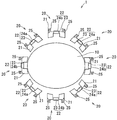
- FIG. 1 is a block diagram of a rotation angle sensor 1 in the present invention.
- the rotation angle sensor 1 according to the present embodiment has an elliptical rotor 10 having N salient poles or N cycles of sinusoidal gap permeance and made of a magnetic material, an exciting coil 23, and a COS output.
- At least one coil 22 of the first output coil 24a or the second output coil 24b for obtaining a SIN output is wound around the yoke 21 and (N ⁇ Y) (Y is 4) at a fixed distance from the rotation axis of the rotor 10
- the magnetic pole unit 20 disposed. That is, the magnetic pole unit 20 is disposed around the rotor 10 (outside the outer periphery of the rotor 10).
- the number of magnetic pole units 20 to be arranged is eight, but by changing the number of N and Y, the shape of the rotor 10 and the number of magnetic pole units 20 can be obtained. It is possible to change and design. Further, as the value of Y increases, the number of magnetic pole units increases, so the output accuracy also improves. Further, even in the case where the winding is directly wound on the yoke 21, the same effect can be obtained even in the case where the yoke 21 is covered with a bobbin made of a resin material and the winding is wound indirectly on the outer periphery of the bobbin.
- the plurality of magnetic pole units 20 may be detachably disposed at a constant distance from the rotation axis of the rotor 10 outside the circumference of the rotor 10, or may be disposed in a state where they are fixed. . Further, as a fixing method of the stopper 25, a method of fixing using a screw or a nut using a hole, a method of inserting the stopper 25 into a member to be fixed, and the like are used.
- FIG. 2 is a block diagram of the magnetic pole unit 20 in the present invention.
- the magnetic pole unit 20 used in the present invention has a U-shaped yoke 21 and a coil 22 wound around a bent portion 27 of the yoke 21 (excitation coil 23 and first output coil 24a (or second output coil 24b)) And a stopper 25 at the end of the yoke 21.
- the magnetic pole unit 20 is disposed such that the opening 26 faces the rotor 10 as shown in FIG. 4 by the fixing method of the stopper 25 described above.
- the yoke 21 of this embodiment has a configuration in which 12 pressed magnetic steel sheets are stacked and integrated by welding or the like.
- the shape of the yoke 21 is expressed as a U-shape, but the U-shape includes a C-shape, a U-shape, a horseshoe shape or the like.
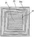
- FIG. 3 is a cross-sectional view of the magnetic pole unit 20 in the present invention taken along the line AA.
- the exciting coil 23 is wound around the bent portion 27 of the yoke 21, and the first output coil 24a (or the second output coil 24b) is wound thereon.
- Table 1 shows an example of the number of turns of the exciting coil 23 and the first output coil 24a (or the second output coil 24b) wound around each yoke 21 and how to wind them.
- the yoke names (A) to (H) correspond to (A) to (H) in FIG. 4 described later.
- the minus notation in Table 1 means reverse winding with respect to the winding direction of the coil in the number of turns not minus notation.
- COS and “SIN” of “the number of turns of output coil” in Table 1 respectively mean so-called “COS winding” and “SIN winding”, and in the present embodiment, the first output for obtaining the COS output respectively
- the coil 24a corresponds to the second output coil 24b that obtains the SIN output.
- the number of turns of the coil may be a distributed winding (the number of turns of the coil also has a sinusoidal distribution) such that the induced electromotive voltage distribution has a sine wave distribution. The same effect as that of the embodiment can be obtained.
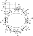
- FIG. 4 is a wiring diagram of the exciting coil 23, the first output coil 24a, and the second output coil 24b in the present invention.
- the exciting coil 23 is electrically connected in series.
- the plurality of magnetic pole units 20 and yokes 21 in FIG. 4 will be described with reference to (A) to (H) as shown in FIG.
- the first output coils 24a wound around the yoke 21 (C), the yoke 21 (E), the yoke 21 (G), and the yoke 21 (A) are electrically connected in series as shown in FIG.
- the second output coil 24b wound around each of the yoke 21 (B), the yoke 21 (D), the yoke 21 (F) and the yoke 21 (H) is electrically connected in series as shown in FIG. Ru.
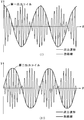
- FIG. 5 is an example of the output result of the rotation angle sensor in the present invention.
- FIG. 5 (I) is an example of the output result by the first output coil 24a
- FIG. 5 (II) is an example of the output result by the second output coil 24b.
- the horizontal axis represents the rotation angle ⁇ of the rotor 10
- the vertical axis represents the voltage value V obtained from the first output coil 24a and the second output coil 24b.
- a sine wave voltage of, for example, 10 kHz and 10 V is excited in the exciting coil 23.
- the rotation of the rotor 10 changes the gap between the rotor 10 and the yoke 21 of the magnetic pole unit 20 disposed at a constant distance from the rotation axis of the rotor 10.
- the magnetic resistance of the yoke 21 changes, and the output voltage generated in the first output coil 24a and the second output coil 24b changes in a sine wave. Since the first output coil 24a and the second output coil 24b are arranged to be changed by 45 degrees in mechanical angle, this structure having an axis double angle 2X changes the phase by 90 degrees and outputs as shown in FIG. .
- the angle of the rotor 10 can be detected by comparing the two outputs of the obtained COS waveform and SIN waveform.
- FIG. 6 shows a rotation angle sensor 30 of a conventional structure.
- the rotor 40, the stator 50, and the 14 pole units 51 projecting on the inner periphery of the stator 50 are provided. The respective positions will be described with reference to (a) to (n).
- the magnetic pole unit 51 includes a coil 52 that is the excitation coil 53 and at least one of the first output coil 54a and the second output coil 54b.
- FIG. 7 is a graph of the result of magnetic field analysis performed on the rotation angle sensor 30 in the conventional structure of FIG. The analysis was performed by winding the coil 52 only on the magnetic pole unit 51 (g).
- the horizontal axis indicates the magnetic pole unit, and the vertical axis indicates the linkage magnetic field. Since the magnetic pole unit 51 is magnetically connected to the stator 50, there is a magnetic flux leakage of about 8% to the magnetic pole unit 51 (f) and the magnetic pole unit 51 (h) adjacent to the magnetic pole unit 51 (g).
- the magnetic pole units 51 (a) to (n) as a whole had a magnetic flux leakage of about 52.4%.
- FIG. 8 is a graph of the result of magnetic field analysis of the rotation angle sensor 1 of the present invention.
- the analysis was performed by winding the coil 22 only on the magnetic pole unit 20 (D) in FIG.
- the horizontal axis indicates the magnetic pole unit, and the vertical axis indicates the linkage magnetic field. Since the magnetic pole unit 20 is magnetically independent, the magnetic flux leakage should be suppressed to about 0.3% with respect to the magnetic pole unit 20 (C) and the magnetic pole unit 20 (E) adjacent to the magnetic pole unit 20 (D). It was possible. Further, the magnetic flux leakage could be suppressed to about 0.65% in the entire magnetic pole units 20 (A) to (H).
- the yield of the magnetic steel sheets can be increased and the cost can be reduced.
- the yoke 21 has a U-shape
- the coil 22 can be wound by rotating the yoke 21.
- the supply tension of the coil wire at the time of winding and the feed pitch in the axial direction can be made accurate, and the aligned winding in which the space factor of the coil is stable becomes possible. Therefore, the output fluctuation due to the variation of the coil space factor is reduced, and the detection accuracy of the rotation angle is improved.
- the coil 22 is wound in two ways in the forward and reverse directions and the number of turns is equal, at least one of the exciting coil 23 and the first output coil 24 a or the second output coil 24 b is used as the plurality of yokes 21.
- the same type of winding coil can be wound simultaneously, it is possible to shorten the tact time.
- a member for fixing the plurality of magnetic pole units 20 it is possible to use a nonmagnetic metal such as aluminum or a nonmagnetic member such as resin. By fixing to the nonmagnetic member as described above, it is possible to suppress the leakage of the magnetic flux, and since each of the magnetic pole units 20 is magnetically independent, the error due to the magnetic flux leakage occurring at the time of driving the rotation angle sensor 1 It becomes possible to prevent.
- the magnetic pole unit 20 is disposed so that the U-shaped opening 26 of the yoke 21 faces the rotor 10, and the gap between the U-shaped yoke 21 and the rotor 10 is As it changes, two outputs of the COS waveform and the SIN waveform are generated in the first output coil 24a and the second output coil 24b, respectively.
- the rotation angle of the rotor 10 can be detected by comparing and processing the COS waveform signal and the SIN waveform signal.
- the exciting coil 23, the first output coil 24a, and the second output coil 24b are wound around the U-shaped bent portion 27 of the yoke 21 as described above, the yoke 21 is not used, and a special winding machine is not used. By winding the exciting coil 23, the first output coil 24a, and the second output coil 24b, thereby winding the exciting coil 23, the first output coil 24a, and the second output coil 24b around the yoke 21. it can.
- the present invention is applicable to a rotation angle sensor that detects the rotation angle of a rotor.
Landscapes
- Physics & Mathematics (AREA)
- General Physics & Mathematics (AREA)
- Transmission And Conversion Of Sensor Element Output (AREA)
Abstract
ヨークを独立させて成形することにより、歩留まりの低減、高価で複雑なコイル巻機を廃しタクトタイムを短縮し、閉磁路を形成することで駆動時に発生する出力の誤差を抑えることを可能にした、回転角度センサの提供をする。 回転角度センサ1は、N個の突極又はNサイクルの正弦波状ギャップパーミアンスを有し、巻線を持たず磁性体で構成されたロータ10と、励磁コイル23と第一出力コイル24aまたは第二出力コイル24bのいずれか一方をヨーク21に巻き付け、ロータ10の周囲に複数個配置する磁極ユニット20と、を備え、磁気ユニット20は、独立した閉磁路を形成する構成である。
Description
本発明は回転角度センサに関する。
磁性体ロータの外周を囲むように内側向きに3種類の巻き線が重ね巻きされた複数個のコイルを有するセンサを配置し、ロータ回転によるローターコイル間ギャップの変化をSIN状の電圧出力に変換するセンサにおいて、固定子に巻くコイル巻き数をSIN分布上に配するとともに、機械巻きを可能にした技術が開示されている(例えば、特許文献1参照。)。
また、特許文献1に対し、出力コイルの巻き数を同じにすることにより、巻線工程を単純化した技術が開示されている(例えば、特許文献2参照。)。
しかしながら、従来技術の特許文献1と特許文献2では、1枚の電磁鋼板からプレスにより成形した固定子を複数枚重ねることにより、磁極ユニットを含む固定子を成形するため、ロータを配置する内周部の電磁鋼板は使用されず、歩留まりが低い問題があった。また、固定子の内周に位置する複数の突起に対し、それぞれコイルを巻かなければならないため、特殊な巻線機が必要になると同時に、複雑な巻線工程が必要なため、タクトタイムが長くなる問題があった。また、ロータの外側にある固定子が磁気的に結合するため、隣り合うコイル同士による磁場干渉が発生し、出力に誤差が生じる問題があった。
本発明は、上記問題に鑑みてなされたものであり電磁鋼板の歩留まりが高く、タクトタイムの短縮が可能で、磁場干渉を低減した回転角度センサを提供することを目的とする。
上述の課題を解決するために講じた第一の課題解決手段は、N個の突極又はNサイクルの正弦波状ギャップパーミアンスを有し、磁性体で構成されるロータと、励磁コイルとCOS出力を得る第一出力コイルおよびSIN出力を得る第二出力コイルの少なくともいずれか一方とを直接的または間接的にヨークに巻き付け、前記ロータの周囲に複数個配置される磁極ユニットと、を備える回転角度センサであって、前記磁極ユニットは、独立した閉磁路を形成していることである。
第二の課題解決手段は、N個の突極又はNサイクルの正弦波状ギャップパーミアンスを有し、磁性体で構成されるロータと、励磁コイルとCOS出力を得る第一出力コイルおよびSIN出力を得る第二出力コイルの少なくともいずれか一方とを直接的または間接的にヨークに巻き付け、前記ロータの周囲に複数個配置される磁極ユニットと、を備える回転角度センサであって、前記磁極ユニットは、非磁性体に固定されることである。
また、第三の課題解決手段は、前記ヨークは、U字型形状を呈することである。
また、第四の課題解決手段は、前記磁極ユニットは、前記ヨークのU字型形状の開口部が前記ロータと対向するように配置されることである。
また、第五の課題解決手段は、前記励磁コイルと前記第一出力コイルと前記第二出力コイルとは、前記ヨークのU字型形状の屈曲部に巻き付けられることである。
また、第六の課題解決手段は、前記第一出力コイルおよび前記第二出力コイルの巻き数とが同数であることである。
また、第七の課題解決手段は、前記磁極ユニットは、前記ロータの回転軸から一定の距離に配置されることである。
また、第八の課題解決手段は、前記ロータは、巻き線を持たない構成であり、前記磁極ユニットは、(N×Y)個配置されることである。
本発明によれば、本発明の回転角度センサは複数の個別の磁極ユニットから構成されているため、この磁極ユニットを構成するヨークが構成される電磁鋼板の歩留まりを高めることができる。また、磁極ユニットが独立することで、各磁極ユニットが独立した閉磁路を形成し、隣り合う磁極ユニットへの磁場干渉が低減して、回転角度の検出精度が向上する。
また、複数の磁極ユニットを独立して設けることで、ヨークを構成する電磁鋼板の歩留まりを高めることができる。そして、磁極ユニットは、非磁性体に固定されるため、各磁極ユニットが独立した閉磁路を形成し、隣り合う磁極ユニットへの磁場干渉が低減して、回転角度の検出精度が向上する。
また、ヨークはU字型形状を呈するため、特殊な巻き線機を用いず、ヨークを回転して、励磁コイルと出力コイルを巻き取ることができる。また、巻線時のコイル線の供給テンションと軸方向の送りピッチを正確にでき、コイル占積率が安定する整列巻きが可能になる。そのため、コイル占積率のばらつきに起因する出力変動が低減し、回転角度の検出精度が向上する。
また、磁極ユニットは、ヨークのU字型形状の開口部がロータと対向するように配置されるため、U字型形状のヨークの両端部とロータとの間のギャップが変化して、第一出力コイルと第二出力コイルに発生するCOS波形とSIN波形の2出力を比較することで、ロータの角度の検出が可能になる。
また、励磁コイルと第一出力コイルと第二出力コイルとは、ヨークのU字型形状の屈曲部に巻き付けられるため、特殊な巻き線機を用いず、ヨークを回転して、励磁コイルと第一出力コイルと第二出力コイルとを巻き取ることができる。また、巻線時のコイル線の供給テンションと軸方向の送りピッチを正確にでき、コイル占積率が安定する整列巻きが可能になる。そのため、回転角度センサの駆動時にコイルから発生するインピーダンスが低減して、出力が向上する。
また、第一出力コイルおよび第二出力コイルの巻き数とが同数であるため、第一出力コイルが巻かれるヨークと第二出力コイルが巻かれるヨークとに対し同時に出力コイルを巻くことが可能で、タクトタイムが低減する。
また、ロータの回転軸から一定の距離に独立した磁極ユニットを複数個配置するため、電磁鋼板の歩留まりを高めることができる。また、磁極ユニットが独立することで、各磁極ユニットが独立した閉磁路を形成し、隣り合う磁極ユニットへの磁場干渉が低減して、回転角度の検出精度が向上する。
また、前記ロータは、巻き線を持たない構成であり、前記磁極ユニットは、(N×Y)個配置されることで、電磁鋼板の歩留まりを高めることができる。また、磁極ユニットが独立することで、各磁極ユニットが独立した閉磁路を形成し、隣り合う磁極ユニットへの磁場干渉が低減して、回転角度の検出精度が向上する。
以下、本実施の形態について図面を参照しつつ詳細に説明する。
図1は、本発明における回転角度センサ1の構成図である。本実施例にかかる回転角度センサ1は、N個の突極又は、Nサイクルの正弦波状ギャップパーミアンスを有し、磁性体で構成される楕円形状のロータ10と、励磁コイル23とCOS出力を得る第一出力コイル24aまたはSIN出力を得る第二出力コイル24bの少なくともいずれか一方のコイル22とをヨーク21に巻き付け、ロータ10の回転軸から一定の距離に(N×Y)個(Yは4以上の整数)配置される磁極ユニット20とを備えている。すなわち、磁極ユニット20はロータ10の周囲(ロータ10の外周外側)に配置されている。
本実施例では、N=2、Y=4としたため、配置する磁極ユニット20の数は8個となるが、NとYの数を変えることで、ロータ10の形状と磁極ユニット20の数を変えて設計することが可能である。また、Yの値が増加すれば磁極ユニットの数が増加するため、出力精度も向上する。また、ヨーク21に対し、巻き線を直接的に巻く場合でも、ヨーク21を樹脂材によるボビンで被ってボビンの外周に間接的に巻き線を巻く場合でも同様の効果が得られる。また、ヨーク21と励磁コイル23に対し、第一出力コイル24aと第二出力コイル24bとを両方巻回した場合、第一出力コイル24aのみを巻回した場合、第二出力コイル24bのみを巻回した場合でも同様の効果を得ることが可能である。なお、複数の磁極ユニット20は、ロータ10の円周外側であって、ロータ10の回転軸から一定の距離に着脱可能に配置されてもよいし、それぞれが固定した状態で配置されてもよい。また、止め具25の固定方法としては、穴部を用いてネジやナットを用いて固定する方法、固定する部材に止め具25をはめ込み固定する方法などが、用いられる。
図2は、本発明における磁極ユニット20の構成図である。本発明で用いる磁極ユニット20は、U字型形状をしたヨーク21と、ヨーク21の屈曲部27に巻回されるコイル22(励磁コイル23と第一出力コイル24a(または第二出力コイル24b))と、ヨーク21の端部に止め具25とを備えている。磁極ユニット20は、上述した止め具25の固定方法により、図4に示されるように、開口部26がロータ10と対向するように配置される。本実施例のヨーク21はプレスした電磁鋼板を12枚重ね、溶接などにより一体化した構成である。なお、本実施例ではヨーク21の形状をU字型形状と表現しているが、U字型形状にはC字型、コ字型、馬蹄形型などの形状を含む。
図3は、本発明における磁極ユニット20のA-A断面図である。まず、ヨーク21の屈曲部27に励磁コイル23を巻き、その上に第一出力コイル24a(または第二出力コイル24b)が巻回される構造になっている。また、各ヨーク21に巻かれた励磁コイル23および第一出力コイル24a(または第二出力コイル24b)の巻き数、巻き方の例を表1に示す。
表1において、ヨーク名の(A)~(H)については後述する図4における(A)~(H)と対応する。表1におけるマイナス表記は、マイナス表記をしていない巻き数におけるコイルの巻き方向に対して逆巻きを意味している。表1における「出力コイル巻き数」の「COS」、「SIN」は、それぞれいわゆる「COS巻線」、「SIN巻線」を意味し、本実施形態においてはそれぞれ、COS出力を得る第一出力コイル24a、SIN出力を得る第二出力コイル24bに対応する。
なお、コイルの巻き数を、誘導起電圧分布が各々正弦波分布となるような分布巻き(そのコイルの巻き数も正弦波分布状となる)としてもよく、このような分布巻きにおいても、本実施例と同様の効果が得られる。

図4は、本発明における励磁コイル23と第一出力コイル24aと第二出力コイル24bの配線図である。励磁コイル23は電気的に直列に接続されている。また、図4における複数の磁極ユニット20及びヨーク21のそれぞれに対して、図4に示すように(A)~(H)の符号を付して説明する。ヨーク21(C)とヨーク21(E)とヨーク21(G)とヨーク21(A)のそれぞれに巻かれる第一出力コイル24aは、図4に示すように電気的に直列に接続される。同様に、ヨーク21(B)とヨーク21(D)とヨーク21(F)とヨーク21(H)のそれぞれに巻かれる第二出力コイル24bも図4に示すように電気的に直列に接続される。
図5は本発明における回転角度センサの出力結果の一例である。図5(I)は第一出力コイル24aによる出力結果の一例、図5(II)は第二出力コイル24bによる出力結果の一例である。横軸は、ロータ10の回転角度θを表し、縦軸は第一出力コイル24aと第二出力コイル24bから得られる電圧値Vを示す。
次に本発明の動作について説明を行う。
上記の構成において、励磁コイル23には、例えば10kHz、10Vの正弦波電圧が励磁される。ロータ10が回転することで、ロータ10と、ロータ10の回転軸から一定の距離に配置されている磁極ユニット20のヨーク21と、の間のギャップが変化する。そうすると、ヨーク21の磁気抵抗が変化し、第一出力コイル24aと第二出力コイル24bに発生する出力電圧が正弦波状に変化する。第一出力コイル24aと第二出力コイル24bは、機械角で45°変化させて配置しているため、軸倍角2Xである本構造は、図5のように位相が90°変化して出力する。それにより、得られるCOS波形とSIN波形の2出力を比較することで、ロータ10の角度を検出が可能となる。
ここで、従来構造と本発明の磁場解析結果について説明する。
図6は、従来構造の回転角度センサ30である。ロータ40と固定子50と固定子50の内周に突起した14個の磁極ユニット51を備えている。それぞれの位置には(a)~(n)の符号を付して説明する。また、磁極ユニット51は、励磁コイル53と第一出力コイル54aおよび第二出力コイル54bの少なくともいずれか一方とであるコイル52を備えている。
図7は、図6の従来構造における回転角度センサ30に対し、磁場解析を行った結果のグラフである。解析は磁極ユニット51(g)にのみコイル52を巻いて実施した。横軸は磁極ユニット、縦軸は鎖交磁場を示す。磁極ユニット51は固定子50と磁気的に繋がっているため、磁極ユニット51(g)と隣り合う磁極ユニット51(f)と磁極ユニット51(h)に対し、それぞれ8%程度の磁束漏れがあった。また、磁極ユニット51(a)~(n)全体では52.4%程度の磁束漏れがあった。
図8は、本発明における回転角度センサ1に対し、磁場解析を行った結果のグラフである。解析は図4における磁極ユニット20(D)にのみコイル22を巻いて実施した。横軸は磁極ユニット、縦軸は鎖交磁場を示す。磁極ユニット20は磁気的に独立しているため、磁極ユニット20(D)と隣り合う磁極ユニット20(C)と磁極ユニット20(E)に対し、それぞれ0.3%程度に磁束漏れを抑えることができた。また、磁極ユニット20(A)~(H)全体では0.65%程度に磁束漏れを抑えることができた。
本実施例のように磁極ユニット20を独立させて成形することで、電磁鋼板の歩留まりが高まり、コスト低減が可能になる。また、ヨーク21はU字型形状を呈しているため、ヨーク21を回転させることでコイル22を巻くことができる。また、巻線時のコイル線の供給テンションと軸方向の送りピッチを正確にでき、コイル占積率が安定する整列巻きが可能になる。そのため、コイル占積率のばらつきに起因する出力変動が低減し、回転角度の検出精度が向上する。また、コイル22の巻き方は順方向と逆方向の2種類、巻き数が等しいことから、励磁コイル23と第一出力コイル24aまたは第二出力コイル24bの少なくともいずれか一方を複数のヨーク21に対して、同種の巻き方のコイルを同時に巻くことができるため、タクトタイムを短縮することが可能になる。
また、複数ある磁極ユニット20を固定する部材として、アルミなどの非磁性体金属、または樹脂などの非磁性体の部材を用いることが可能である。上記のような非磁性体の部材に固定することにより、磁束の漏れを抑えることができ、磁極ユニット20はそれぞれが磁気的に独立するため、回転角度センサ1駆動時に発生する磁束漏れによる誤差を防止することが可能になる。
また、磁極ユニット20は、ヨーク21のU字型形状の開口部26がロータ10と対向するように配置されており、U字型形状のヨーク21の両端部とロータ10との間のギャップが変化して、第一出力コイル24aと第二出力コイル24bとにそれぞれCOS波形とSIN波形との2出力が発生する。このCOS波形の信号とSIN波形の信号とを比較・処理等することで、ロータ10の回転角度の検出が可能になる。
また、励磁コイル23、第一出力コイル24a、第二出力コイル24bは、上述したようにヨーク21のU字型形状の屈曲部27に巻き付けられるため、特殊な巻き線機を用いず、ヨーク21を回転させて励磁コイル23と第一出力コイル24aと第二出力コイル24bとを巻き取ることで、励磁コイル23、第一出力コイル24a、第二出力コイル24bをヨーク21へ巻回させることができる。
本発明は、ロータの回転角度を検出する回転角度センサに適用可能である。
1・・・回転角度センサ、 10・・・ロータ、 20・・・磁極ユニット、21・・・ヨーク、 23・・・励磁コイル、 24a・・・第一出力コイル、 24b・・・第二出力コイル、 26・・・開口部、 27・・・屈曲部
Claims (8)
- N個の突極又はNサイクルの正弦波状ギャップパーミアンスを有し、磁性体で構成されるロータと、
励磁コイルとCOS出力を得る第一出力コイルおよびSIN出力を得る第二出力コイルの少なくともいずれか一方とを直接的または間接的にヨークに巻き付け、前記ロータの周囲に複数個配置される磁極ユニットと、
を備える回転角度センサであって、
前記磁極ユニットは、独立した閉磁路を形成することを特徴とする回転角度センサ。 - N個の突極又はNサイクルの正弦波状ギャップパーミアンスを有し、磁性体で構成されるロータと、
励磁コイルとCOS出力を得る第一出力コイルおよびSIN出力を得る第二出力コイルの少なくともいずれか一方とを直接的または間接的にヨークに巻き付け、前記ロータの周囲に複数個配置される磁極ユニットと、
を備える回転角度センサであって、
前記磁極ユニットは、非磁性体に固定されることを特徴とする回転角度センサ。 - 前記ヨークは、U字型形状を呈することを特徴とする請求項1または2に記載の回転角度センサ。
- 前記磁極ユニットは、前記ヨークのU字型形状の開口部が前記ロータと対向するように配置されることを特徴とする請求項3に記載の回転角度センサ。
- 前記励磁コイルと前記第一出力コイルと前記第二出力コイルとは、前記ヨークのU字型形状の屈曲部に巻き付けられることを特徴とする請求項3または4に記載の回転角度センサ。
- 前記第一出力コイルおよび前記第二出力コイルの巻き数とが同数であることを特徴とする請求項1乃至5の何れか一項に記載の回転角度センサ。
- 前記磁極ユニットは、前記ロータの回転軸から一定の距離に配置されることを特徴とする請求項1乃至6のいずれか一項に記載の回転角度センサ。
- 前記ロータは、巻き線を持たない構成で、前記磁極ユニットは、(N×Y)個配置されることを特徴とする請求項1乃至7のいずれか一項に記載の回転角度センサ。
Applications Claiming Priority (4)
| Application Number | Priority Date | Filing Date | Title |
|---|---|---|---|
| JP2009-200210 | 2009-08-31 | ||
| JP2009200210 | 2009-08-31 | ||
| JP2010156427A JP2011069811A (ja) | 2009-08-31 | 2010-07-09 | 回転角度センサ |
| JP2010-156427 | 2010-07-09 |
Publications (1)
| Publication Number | Publication Date |
|---|---|
| WO2011024678A1 true WO2011024678A1 (ja) | 2011-03-03 |
Family
ID=43627783
Family Applications (1)
| Application Number | Title | Priority Date | Filing Date |
|---|---|---|---|
| PCT/JP2010/063902 Ceased WO2011024678A1 (ja) | 2009-08-31 | 2010-08-18 | 回転角度センサ |
Country Status (2)
| Country | Link |
|---|---|
| JP (1) | JP2011069811A (ja) |
| WO (1) | WO2011024678A1 (ja) |
Families Citing this family (1)
| Publication number | Priority date | Publication date | Assignee | Title |
|---|---|---|---|---|
| JP2021060263A (ja) * | 2019-10-07 | 2021-04-15 | 多摩川精機株式会社 | 二重冗長系レゾルバ |
Citations (4)
| Publication number | Priority date | Publication date | Assignee | Title |
|---|---|---|---|---|
| JP2003207370A (ja) * | 2002-01-11 | 2003-07-25 | Okuma Corp | リラクタンス型レゾルバ |
| JP2003287441A (ja) * | 2002-03-27 | 2003-10-10 | Minebea Co Ltd | 回転位置検出器 |
| JP2007285774A (ja) * | 2006-04-13 | 2007-11-01 | Toyota Motor Corp | 磁気レゾルバ及びその製造方法 |
| JP2009174925A (ja) * | 2008-01-22 | 2009-08-06 | Tamagawa Seiki Co Ltd | 回転角度検出装置 |
Family Cites Families (3)
| Publication number | Priority date | Publication date | Assignee | Title |
|---|---|---|---|---|
| JPH065161B2 (ja) * | 1984-08-23 | 1994-01-19 | 株式会社エスジー | 分離されたステータコアを有する誘導形位置検出器 |
| JP2006023146A (ja) * | 2004-07-07 | 2006-01-26 | Honda Motor Co Ltd | 回転位置検出装置 |
| JP2008175553A (ja) * | 2007-01-16 | 2008-07-31 | Tamagawa Seiki Co Ltd | 角度検出器 |
-
2010
- 2010-07-09 JP JP2010156427A patent/JP2011069811A/ja active Pending
- 2010-08-18 WO PCT/JP2010/063902 patent/WO2011024678A1/ja not_active Ceased
Patent Citations (4)
| Publication number | Priority date | Publication date | Assignee | Title |
|---|---|---|---|---|
| JP2003207370A (ja) * | 2002-01-11 | 2003-07-25 | Okuma Corp | リラクタンス型レゾルバ |
| JP2003287441A (ja) * | 2002-03-27 | 2003-10-10 | Minebea Co Ltd | 回転位置検出器 |
| JP2007285774A (ja) * | 2006-04-13 | 2007-11-01 | Toyota Motor Corp | 磁気レゾルバ及びその製造方法 |
| JP2009174925A (ja) * | 2008-01-22 | 2009-08-06 | Tamagawa Seiki Co Ltd | 回転角度検出装置 |
Also Published As
| Publication number | Publication date |
|---|---|
| JP2011069811A (ja) | 2011-04-07 |
Similar Documents
| Publication | Publication Date | Title |
|---|---|---|
| JP5058849B2 (ja) | ブラシレスモータ | |
| JP4654348B1 (ja) | 検出装置用巻線の正弦波巻線方法 | |
| JP4775294B2 (ja) | レゾルバ | |
| US8269487B2 (en) | Sheet coil type resolver | |
| US11152875B2 (en) | Multigroup-multiphase rotary electrical machine control device and multigroup-multiphase rotary electrical machine drive device | |
| JP2009213284A (ja) | ブラシレスモータ | |
| US7183952B1 (en) | Resolver | |
| CN103890546A (zh) | 用于磁阻式传感器的磁通量增强器系统 | |
| EP3799277B1 (en) | Rotary transformer | |
| JP2013233085A (ja) | 電機子の巻線巻回方法 | |
| KR101964371B1 (ko) | 리졸버 및 그 제조 방법 | |
| JP6529662B2 (ja) | レゾルバ | |
| US9441942B2 (en) | Resolver and multiple-rotation detector | |
| US20210119497A1 (en) | Electric motor | |
| JP5363136B2 (ja) | ブラシレスモータ | |
| JP4882513B2 (ja) | 回転角検出装置およびトルクセンサ | |
| CN112368921B (zh) | 旋转变压器装置及带旋转变压器装置旋转电机 | |
| JP2011069811A (ja) | 回転角度センサ | |
| JP5331672B2 (ja) | 回転角センサ | |
| JP2009300238A (ja) | 可変リラクタンス型レゾルバ | |
| JP6976243B2 (ja) | レゾルバ | |
| JP5024893B2 (ja) | 可変リラクタンス型レゾルバ | |
| JP2013027130A (ja) | レゾルバ | |
| JP5182759B2 (ja) | レゾルバー及びレゾルバーの製造方法 | |
| JP4896910B2 (ja) | 円弧型角度センサ |
Legal Events
| Date | Code | Title | Description |
|---|---|---|---|
| 121 | Ep: the epo has been informed by wipo that ep was designated in this application |
Ref document number: 10811728 Country of ref document: EP Kind code of ref document: A1 |
|
| NENP | Non-entry into the national phase |
Ref country code: DE |
|
| 122 | Ep: pct application non-entry in european phase |
Ref document number: 10811728 Country of ref document: EP Kind code of ref document: A1 |