WO2011010577A1 - 保温構造の補修方法及び保温構造 - Google Patents
保温構造の補修方法及び保温構造 Download PDFInfo
- Publication number
- WO2011010577A1 WO2011010577A1 PCT/JP2010/061830 JP2010061830W WO2011010577A1 WO 2011010577 A1 WO2011010577 A1 WO 2011010577A1 JP 2010061830 W JP2010061830 W JP 2010061830W WO 2011010577 A1 WO2011010577 A1 WO 2011010577A1
- Authority
- WO
- WIPO (PCT)
- Prior art keywords
- heat insulating
- repair
- heat
- exterior
- exterior material
- Prior art date
- Legal status (The legal status is an assumption and is not a legal conclusion. Google has not performed a legal analysis and makes no representation as to the accuracy of the status listed.)
- Ceased
Links
Images


Classifications
-
- F—MECHANICAL ENGINEERING; LIGHTING; HEATING; WEAPONS; BLASTING
- F16—ENGINEERING ELEMENTS AND UNITS; GENERAL MEASURES FOR PRODUCING AND MAINTAINING EFFECTIVE FUNCTIONING OF MACHINES OR INSTALLATIONS; THERMAL INSULATION IN GENERAL
- F16L—PIPES; JOINTS OR FITTINGS FOR PIPES; SUPPORTS FOR PIPES, CABLES OR PROTECTIVE TUBING; MEANS FOR THERMAL INSULATION IN GENERAL
- F16L59/00—Thermal insulation in general
- F16L59/10—Bandages or covers for the protection of the insulation, e.g. against the influence of the environment or against mechanical damage
-
- F—MECHANICAL ENGINEERING; LIGHTING; HEATING; WEAPONS; BLASTING
- F16—ENGINEERING ELEMENTS AND UNITS; GENERAL MEASURES FOR PRODUCING AND MAINTAINING EFFECTIVE FUNCTIONING OF MACHINES OR INSTALLATIONS; THERMAL INSULATION IN GENERAL
- F16L—PIPES; JOINTS OR FITTINGS FOR PIPES; SUPPORTS FOR PIPES, CABLES OR PROTECTIVE TUBING; MEANS FOR THERMAL INSULATION IN GENERAL
- F16L59/00—Thermal insulation in general
- F16L59/02—Shape or form of insulating materials, with or without coverings integral with the insulating materials
- F16L59/029—Shape or form of insulating materials, with or without coverings integral with the insulating materials layered
Definitions
- the present invention relates to a thermal insulation structure repair method and a thermal insulation structure, and more particularly to repair of an existing thermal insulation structure.
- Patent Document 1 describes that the outer periphery of a pipe is covered with a heat insulating material, and further, the outer periphery of the heat insulating material is covered with a protective cover made of a metal plate.
- This invention was made in view of the said subject, Comprising: By the repair method of the thermal insulation structure which can construct
- a method for repairing a heat retaining structure according to an embodiment of the present invention for solving the above problems is a method for repairing an existing heat retaining structure having a heat retaining body and a heat retaining material that covers the heat retaining body.
- the repair method of the heat retention structure which can construct
- the existing heat insulation structure is an existing pipe heat insulation structure including the heat retaining body that is a pipe through which a fluid flows, and the heat insulation material that covers an outer periphery of the pipe, and the new heat insulation structure.
- the structure may be a new pipe heat insulation structure including the pipe, the heat insulating material, the repair material covering the outer periphery of the heat insulating material, and the exterior material covering the outer periphery of the repair material.
- the new pipe heat insulating structure includes the pipe, the heat insulating material, a first exterior material that covers an outer periphery of the heat insulating material, the repair material that covers an outer periphery of the first exterior material, The exterior material that is the second exterior material that covers the outer periphery of the repair material, and a drain hole penetrating the first exterior material, the repair material, and the second exterior material is formed in a lower portion thereof. It is good to be.
- the existing pipe heat insulating structure further includes a metal existing outer covering material that covers an outer periphery of the heat insulating material, and in the new pipe heat insulating structure, the first outer covering material is the existing outer covering material. It is good also as being.
- the first exterior material, the repair material, and the second exterior are covered by covering the outer periphery of the first exterior material with the repair material and covering the outer periphery of the repair material with the second exterior material. It is good also as laminating
- the existing pipe heat insulating structure further includes a metal existing outer covering material that covers the outer periphery of the heat insulating material, and the existing outer heat insulating material is removed from the existing pipe heat insulating structure, and then the outer periphery of the heat insulating material is removed. It is good also as constructing the said new piping heat insulation structure by covering with the said repair material and covering the outer periphery of the said repair material with the said exterior material.
- the repair material may be a fibrous body filled with airgel.
- a thermal insulation structure according to an embodiment of the present invention for solving the above-described problems is constructed by any one of the repair methods described above.
- ADVANTAGE OF THE INVENTION According to this invention, the new heat retention structure where the heat insulation property improved effectively compared with the existing heat retention structure can be provided.
- a heat insulation structure repair method capable of constructing a new heat insulation structure in which the heat insulation performance is effectively improved as compared with the existing heat insulation structure, and a heat insulation structure constructed thereby.
- FIG. It is a perspective view of the existing piping heat retention structure repaired in an example of the repair method which concerns on one Embodiment of this invention. It is sectional drawing of the existing piping heat retention structure shown in FIG. It is a perspective view of the piping heat insulation structure constructed
- the present method a heat insulation structure repair method (hereinafter referred to as “the present method”) and a heat insulation structure constructed thereby (hereinafter referred to as “the present structure”) according to an embodiment of the present invention will be described.
- This method is a method of repairing an existing heat retaining structure having a heat retaining body that is a structure to be heat retained, and a heat insulating material that covers the heat retaining body provided to heat the heat retaining body.
- the existing heat retaining structure is mainly an example of an existing pipe heat retaining structure having a heat retaining body that is a pipe through which a fluid flows and a heat insulating material that covers an outer periphery of the pipe.
- the present invention is not limited to this embodiment.
- FIG. 1 is a perspective view of an existing pipe heat insulation structure (hereinafter referred to as “piping structure 1”) to be repaired in an example of the present method
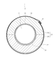
- FIG. 2 is a cross-sectional view of the piping structure 1.
- the pipe structure 1 includes a pipe 10 through which a fluid flows, a heat insulating material 20 that covers the outer periphery of the pipe 10, and a metal exterior material that covers the outer periphery of the heat insulating material 20. (Hereinafter referred to as “existing exterior material 30”).
- existing exterior material 30 is a perspective view of an existing pipe heat insulation structure to be repaired in an example of the present method
- FIG. 2 is a cross-sectional view of the piping structure 1.
- the pipe structure 1 includes a pipe 10 through which a fluid flows, a heat insulating material 20 that covers the outer periphery of the pipe 10, and a metal exterior material that covers the outer periphery of the heat insulating material 20.
- the pipe 10 is installed to transport a liquid or gas having a temperature higher than the outside air temperature of the environment where the pipe structure 1 is arranged.
- the temperature of the pipe 10 is, for example, 40 ° C. or more, and more specifically, for example, in the range of 40 to 500 ° C.
- the pipe 10 is made of a metal such as carbon steel or stainless steel, for example. In the hollow portion 11 formed in the pipe 10, a liquid or gas to be transported flows.
- the heat insulating material 20 is a heat insulating material provided in order to suppress the cooling by the external air of the piping 10.
- the heat insulating material that can be used as the heat insulating material 20 is not particularly limited as long as it is a member having an appropriate heat insulating property according to the purpose.
- heat insulating materials such as calcium silicate (zonolite-based calcium silicate), perlite, and the like. Insulating inorganic porous bodies such as glass wool and rock wool can be preferably used.
- the heat insulating material 20 a material formed as a cylindrical molded body that can be divided into a plurality of pieces in the circumferential direction can be used. That is, in the example shown in FIGS. 1 and 2, the heat insulating material 20 is formed as a cylindrical molded body that can be divided into two parts. Specifically, the heat insulating material 20 includes a semi-cylindrical upper heat insulating material 20a covering the outer periphery of the upper portion of the pipe 10, and a semi-cylindrical lower heat insulating material 20b covering the outer periphery of the lower portion of the pipe 10. And is composed of. The heat insulating material 20 can also be formed so as to be divided into three or more (for example, four) portions. Moreover, the heat insulating material 20 is not restricted to what was formed so that division
- a heat insulating inorganic porous molded body or an inorganic fiber body that has been subjected to a treatment for enhancing its water repellency can also be used.
- a water repellent treatment cannot impart sufficient water impermeability to the heat insulating material 20, and the heat insulating material 20 has a certain amount of water permeability.
- the existing exterior member 30 is a metal cover member provided to protect the heat insulating material 20.
- a metal plate such as a colored plated steel plate or a stainless steel plate can be preferably used.
- the existing exterior member 30 is formed by winding a metal plate around the outer periphery of the heat insulating material 20 and caulking one end and the other end in the circumferential direction of the metal plate. .
- the existing exterior member 30 has a caulking portion 31 extending in the longitudinal direction.
- a plurality of existing exterior materials 30 having a predetermined length are connected and provided (not shown).
- the plurality of existing exterior materials 30 are preferably provided such that the positions of the joints are shifted from the positions of the joints of the plurality of heat insulating materials 20 described above.
- the piping structure 1 is installed outdoors. That is, the piping structure 1 is installed in an environment that can be exposed to rain or snow, for example.
- the existing exterior material 30 covers the entire outer periphery of the heat insulating material 20 as the outermost layer, it is possible to prevent water from entering the heat insulating material 20 due to rain or snow to some extent. is made of.
- the existing exterior material 30 is constructed by winding a metal plate around the outer periphery of the heat insulating material 20 and caulking the end portion, a seam (caulking portion 31) is formed in the existing exterior material 30. . Therefore, when rain or snow is strongly blown against the piping structure 1, water may infiltrate between the existing exterior material 30 and the heat insulating material 20 from the gap between the seams of the existing exterior material 30.
- the infiltrated water permeates from the portion corresponding to the joint of the existing exterior material 30 into the other outer peripheral portion of the heat insulating material 20 and further penetrates into the heat insulating material 20.
- water having a thermal conductivity higher than that of air is retained in the space inside the heat insulating material 20 made of the heat insulating inorganic porous molded body or the inorganic fiber body. It will decline.
- the pipe 10 when moisture enters the heat insulating material 20, the pipe 10 is easily corroded. That is, for example, when water exists on the surface of the pipe 10 and the temperature of the pipe 10 becomes a temperature suitable for the corrosion reaction (for example, around 60 to 80 ° C.), the pipe 10 is newly corroded. Or the generated corrosion is likely to proceed.
- the components involved in the corrosion contained in the heat insulating material 20 and the salts contained in the water are eluted and accumulated in the vicinity of the pipe 10, Corrosion of the pipe 10 can be promoted. Corrosion tends to proceed even when the rust-proof coating of the pipe 10 is deteriorated.
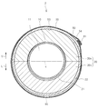
- FIG. 3 is a perspective view of the structure 2 constructed by an example of the method
- FIG. 4 is a cross-sectional view of the structure 2.
- this structure 2 is made of a metal that covers the outer periphery of the heat insulating material 20 in addition to the pipe 10 and the heat insulating material 20 of the existing piping structure 1 (see FIGS. 1 and 2). It has the 1st exterior material 40, the repair material 50 which covers the outer periphery of the said 1st exterior material 40, and the metal 2nd exterior material 60 which covers the outer periphery of the said repair material 50.
- the first exterior material 40 is a metal cover member provided to protect the heat insulating material 20.
- metal plates such as a coloring plating steel plate and a stainless plate, can be used preferably, for example.
- the first exterior member 40 is formed by winding a metal plate around the outer periphery of the heat insulating material 20 and caulking one end and the other end in the circumferential direction of the metal plate. Yes. For this reason, the first exterior member 40 has a caulking portion 41 extending in the longitudinal direction. In the example shown in FIG. 4, a gap is formed between the heat insulating material 20 and the first exterior material 40 in the lower portion of the structure 2.
- a plurality of first exterior materials 40 having a predetermined length are connected and provided (not shown).
- the plurality of first exterior members 40 are preferably provided such that the positions of the joints are shifted from the positions of the joints of the plurality of heat insulating materials 20 described above.
- the first exterior material 40 can be the existing exterior material 30 (see FIGS. 1 and 2) of the existing piping structure 1. That is, the first exterior material 40 can be formed by reusing the existing exterior material 30. When the existing exterior material 30 is used as the first exterior material 40, the time and cost required for repair work in this method can be effectively reduced.
- the first exterior material 40 may be an unused new cover material provided in place of the existing exterior material 30.
- the repair material 50 has heat insulating properties, water vapor permeability, and non-water permeability. That is, the repair material 50 has a heat insulating property capable of increasing the temperature of the outer surface 22 of the heat insulating material 20 as compared with the case where the repair material 50 is not provided.
- the repair material 50 also has water vapor permeability that allows water vapor generated in the heat insulating material 20 (that is, water in a gaseous state) to pass therethrough. Furthermore, the repair material 50 also has non-permeability that liquid water cannot permeate even when exposed to strong rain or wind.
- a heat insulating material having both water vapor permeability and non-water permeability can be used. That is, as the repair material 50, for example, a fiber body filled with airgel (hereinafter referred to as “airgel fiber body”) can be preferably used.
- airgel fiber body a fiber body filled with airgel
- This airgel fiber body is a heat insulating structure that can be manufactured by filling a fiber substrate with airgel.
- the airgel fiber body can be produced, for example, by impregnating the airgel raw material between the fibers of the fiber base material, and then supercritically drying the fiber base material impregnated with the airgel raw material.
- a woven fabric or a non-woven fabric of inorganic fibers or organic fibers can be used as the fiber substrate constituting the airgel fiber body.
- a nonwoven fabric in which fibers are entangled irregularly as a fiber base material the airgel can be more effectively held between the fibers.
- fibers constituting the fiber base material for example, resin fibers such as polyethylene terephthalate (PET) fibers, ceramic fibers such as carbon fibers, glass fibers, and alumina fibers can be used.
- PET polyethylene terephthalate
- ceramic fibers such as carbon fibers, glass fibers, and alumina fibers
- an airgel made of an inorganic material (inorganic airgel) or an airgel made of an organic material (organic airgel) can be used.
- inorganic airgel By using the inorganic airgel, the heat resistance of the airgel fiber can be effectively increased.
- silica airgel or alumina airgel can be used as the inorganic airgel.
- the heat insulation of an airgel fiber body can be effectively improved by using a silica airgel.
- repair material 50 a material having higher heat insulation than the heat insulating material 20 of the existing piping structure 1 can be preferably used. That is, for example, the repair material 50 whose thermal conductivity is lower than the thermal conductivity of the heat insulating material 20 can be preferably used.
- the thermal conductivity at 25 ° C. of the repair material 50 measured by a method based on ASTM C177 is preferably 0.05 W / (m ⁇ K) or less, for example, 0.02 W / (m -K) More preferably, it is below.
- an airgel fiber body whose thermal conductivity is in the above range can be preferably used as the repair material 50.
- gap between the fibers of an airgel fiber body can prevent effectively the convection of the air in the inside of the said airgel fiber body by the micropore in the said airgel. For this reason, an airgel fiber body can have the outstanding heat insulation.
- the water vapor permeability of the repair material 50 measured by a method based on ASTM E96 (Procedure B) is preferably 600 ng / (Pa ⁇ S ⁇ m 2 ) or more, for example, 1500 ng / (Pa ⁇ S). ⁇ m 2) or more is more preferably.
- the water absorption rate after the immersion of the repair material 50 measured by a method based on ASTM C1104 is, for example, preferably 10% by weight or less, and more preferably 4% by weight or less.
- the water repellency of the repair material 50 measured by a method based on ASTM C1511 is, for example, preferably 5 g weight loss or less, and more preferably 3 g weight loss or less.
- an airgel fiber body further provided with either or both of the water absorption rate and the water repellency in the above range can be preferably used.
- the airgel fiber body can have the above water vapor permeability and water impermeability in addition to the excellent heat insulating property due to the fine pores in the airgel as described above.
- the bulk density of the airgel fiber body is preferably in the range of 100 to 300 kg / m 3 , for example, in the range of 150 to 200 kg / m 3. More preferred.
- the structure 2 can be reduced in weight.
- the repair material 50 has moderate flexibility. That is, as the repair material 50, a sheet-like body having flexibility that can be wound around the outer periphery of the heat insulating material 20 and the first exterior material 40 of the pipe structure 1 can be used.
- a sheet of an airgel fiber body in which a fiber base material that is a nonwoven fabric is filled with airgel can be preferably used.
- the thickness of the airgel fiber body is, for example, preferably in the range of 2 to 20 mm, and more preferably in the range of 3 to 10 mm.
- a plurality of repair materials 50 having a predetermined length are connected and provided. That is, in the example illustrated in FIG. 3, in the longitudinal direction of the pipe 10, the first repair material 50 a provided on one side (for example, the upstream side of the pipe 10) and the other side (for example, the downstream side of the pipe 10). The provided second repair material 50b is connected.
- the overlap part 51 is formed in the longitudinal direction of the piping 10 by overlapping a part of 1st repair material 50a and a part of 2nd repair material 50b. That is, in the outer periphery of the first exterior material 40, the overlapping portion 51 is such that the upstream end 51b of the second repair material 50b is superimposed on the downstream end 51a of the first repair material 50a. It is formed by.
- the plurality of repair materials 50 are provided so that the positions of the overlapping portions 51 that are the joints are shifted from the positions of the joints of the plurality of first exterior materials 40 described above.
- the repair material 50 is formed by winding a sheet-like body (for example, an airgel fiber body) of a predetermined length around the outer periphery of the first exterior member 40, and the circumferential direction of the sheet-like body Are formed by superimposing one end and the other end.
- the repair material 50 is bound by winding a plurality of wire W around the outer periphery of each repair material 50.
- the second exterior material 60 is a metal cover member provided mainly to protect the repair material 50.
- metal plates such as a coloring plating steel plate and a stainless plate, can be used preferably, for example.
- the second exterior member 60 is formed by winding a metal plate around the outer periphery of the repair material 50 and caulking one end and the other end in the circumferential direction of the metal plate. Yes. For this reason, the second exterior member 60 has a caulking portion 61 extending in the longitudinal direction.
- a plurality of second exterior materials 60 having a predetermined length are connected and provided (not shown).
- the plurality of second exterior members 60 are preferably provided so that the positions of the joints are shifted from the positions of the joints (overlapping portions 51) of the plurality of repair materials 50 described above.
- the drain hole 70 which penetrates the 1st exterior material 40, the repair material 50, and the 2nd exterior material 60 is formed in the downward part as shown in FIG. That is, in the example shown in FIG. 4, the through hole 42 formed in the lower portion of the first exterior member 40, the through hole 52 formed in the lower portion of the repair material 50, and the lower portion of the second exterior member 60.
- the drain holes 70 are formed by arranging the through holes 62 formed in the above so as to be continuous in the radial direction of the pipe 10.
- the lower side portion of the structure 2 is, for example, in the example shown in FIG. 4, in the structure 2 below the horizontal line H passing through the center of the pipe 10 in the radial direction (arrow shown in FIG. 4). This is a portion on the side in the direction indicated by L.
- one drain hole 70 is formed at the apex portion on the lower side in the vertical direction in the structure 2, but the mode of the drain hole 70 is not limited to this. That is, the drain hole 70 is, for example, water that has entered between the heat insulating material 20 and the first exterior material 40 or between the repair material 50 and the second exterior material 60 and has flowed downward due to the action of gravity. A proper number is formed at a suitable position so as to be discharged from the drain hole 70.
- the drain holes 70 can be formed at a plurality of positions in the longitudinal direction, and the drain holes 70 can be formed at a plurality of positions in the circumferential direction.
- the drainage is performed so that one or more drain holes 70 are opened in each second exterior member 60.
- a hole 70 can be provided.
- the caulking portion 41 of the first exterior material 40, the overlapping portion 51 in the circumferential direction of the repair material 50, and the caulking portion 61 of the second exterior material 60 are all of the structure 2.
- Upper part in the example shown in FIG. 4, in the structure 2, above the horizontal line H passing through the center in the radial direction of the pipe 10 in the upper part in the vertical direction (the direction indicated by the arrow U shown in FIG. 4)). Is formed.
- this structure 2 shown in FIGS. 3 and 4 by this method, for example, by covering the outer periphery of the first exterior material 40 with the repair material 50 and covering the outer periphery of the repair material 50 with the second exterior material 60.
- the first exterior material 40, the repair material 50, and the second exterior material 60 are stacked, and then the drainage that penetrates the stacked first exterior material 40, the repair material 50, and the second exterior material 60.
- a hole 70 can be formed.
- the existing exterior material 30 (see FIGS. 1 and 2) of the existing piping structure 1 is used as the first exterior material 40
- first the existing exterior material 30 (first exterior material 40).
- the repair material 50 is wound around the outer periphery of the repair material 50, and then a new second exterior material 60 is wound around the outer periphery of the repair material 50.
- the plurality of repair materials 50 are partially overlapped with each other in the longitudinal direction (a pair of adjacent repair materials 50a and 50b are preferably arranged so that an overlapping portion 51 is formed at the joint portion.
- first exterior material 40 When a new exterior material is used as the first exterior material 40, first, the existing exterior material 30 of the existing piping structure 1 is removed, and the outer periphery of the heat insulating material 20 is replaced with the existing exterior material 30. The first exterior material 40 is wound around, the repair material 50 is then wound around the outer periphery of the first exterior material 40, and the new second exterior material 60 is wound around the outer periphery of the repair material 50.
- a drain hole 70 as shown in FIG. 4 is formed by sequentially forming a through hole 62 of the material 60, a through hole 52 of the repair material 50, and a through hole 42 of the first exterior material 40.
- through holes 42, 52, 62 are formed in advance in each of the first exterior material 40, the repair material 50, and the second exterior material 60, and when these members are constructed, the through holes 42, 52 are formed. , 62 can be aligned to form a drain hole 70. Moreover, among the through holes 42, 52, and 62 of the first exterior material 40, the repair material 50, and the second exterior material 60, a part may be formed before construction, and the other part may be formed after construction. it can.
- the heat insulating material 20 of the existing piping structure 1 is covered with the repair material 50 and the second exterior material 60 having the above-described characteristics, and the drain hole 70 is formed.
- the heat insulating property of the heat insulating material 20 can be effectively recovered. That is, in the existing piping structure 1, when the heat insulating material 20 includes water that has entered from the outside, and the heat insulating property of the heat insulating material 20 is deteriorated, water is discharged from the heat insulating material 20 by this method. It can be discharged effectively.
- the temperature of the outer surface 22 of the heat insulating material 20 is increased, and the temperature and inner surface of the outer surface 22 of the heat insulating material 20 are increased.
- the difference from the temperature of 21 can be reduced.
- the repair material 50 which covers the heat insulating material 20 has the water vapor permeability which the vaporized water can permeate
- the heat insulating material 20 containing water can be effectively dried once and the heat insulating property can be recovered by a simple operation of covering the existing heat insulating material 20 with the repair material 50. .
- the water that has entered the inside can be effectively discharged from the discharge hole 70. That is, by providing the repair material 50 as described above, the water contained in the heat insulating material 20 can be effectively evaporated.
- the temperature of the first exterior material 40 and the second exterior material 60 Is lower than the temperature of the outer surface 22 of the heat insulating material 20, the water vapor between the heat insulating material 20 and the first exterior material 40 or between the repair material 50 and the second exterior material 60. Can condense and produce water droplets again.
- the drainage hole 70 penetrating the first exterior material 40, the repair material 50, and the second exterior material 60 is formed in the lower portion thereof. Water accumulated in the lower part of the structure 2 can be efficiently discharged from the drain hole 70.
- this structure 2 constructed by this method also has the heat-insulating repair material 50 in addition to the heat insulating material 20, it can have a higher heat-insulating property than the piping structure 1 before repair.
- the repair material 50 when an airgel fiber body having a high heat insulating property in a thin sheet shape is used as the repair material 50, the present structure 2 in which the heat insulating property is remarkably improved while suppressing an increase in the radial size accompanying the repair. Simple and reliable construction is possible.
- repair material 50 that covers the heat insulating material 20 is impermeable to water, for example, even when the present structure 2 is exposed to rain or snow, water may newly enter the heat insulating material 20. Can be effectively prevented.
- the infiltrated water can be effectively discharged. That is, in this case, in the present structure 2, the water newly contained in the heat insulating material 20 is evaporated and discharged through the repair material 50 as described above, and the newly entered water and water vapor are condensed and generated. By discharging the water droplets from the drain hole 70, the heat insulating material 20 can be dried again. That is, the present structure 2 has a heat-insulating self-healing ability. Therefore, in this structure 2, the high heat insulation can be stably maintained.
- the corrosion of the pipe 10 can be effectively avoided as compared with the existing pipe structure 1. That is, in the present structure 2, as described above, the water that has once entered the interior of the present structure 2 such as water contained in the heat insulating material 20 or water droplets generated by condensation of water vapor is used as the repair material 50. And can be quickly discharged through the drain hole 70. Therefore, in this structure 2, it is effective that substances that can cause corrosion, such as infiltrated moisture, salts contained in the moisture, and components eluted from the heat insulating material 20, are present near the surface of the pipe 10. Can be avoided. As a result, in the present structure 2, the occurrence and progression of corrosion of the pipe 10 can be effectively prevented.
- the mechanical strength of the present structure 2 can be improved by providing the metal second exterior material 60 as the outermost layer. For this reason, for example, an operator can get on the structure 2 (that is, on the second exterior material 60) and perform a predetermined work.
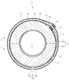
- FIG. 5 is a perspective view of the present structure 2 constructed by another example of the present method
- FIG. 6 is a cross-sectional view of the present structure 2.
- the structure 2 includes a repair material 50 that covers the outer periphery of the heat insulating material 20 in addition to the pipe 10 and the heat insulating material 20 of the existing piping structure 1 (see FIGS. 1 and 2).
- a metal exterior material 80 that covers the outer periphery of the repair material 50.
- repair material 50 a heat insulating material having both water vapor permeability and non-water permeability, such as an airgel fiber body, can be used as in the above example.
- the repair material 50 can also be applied in the same manner as in the above example.
- the exterior material 80 is a metal cover member provided mainly to protect the heat insulating material 20 and the repair material 50.
- a metal plate such as a colored plated steel plate or a stainless steel plate can be preferably used.
- the exterior material 80 is formed by winding a metal plate around the outer periphery of the repair material 50 and caulking one end and the other end of the metal plate in the circumferential direction. For this reason, the exterior material 80 has a caulking portion 81 extending in the longitudinal direction.
- a plurality of exterior members 80 having a predetermined length are connected and provided (not shown).
- the plurality of exterior members 80 are preferably provided so that the positions of the joints are shifted from the positions of the joints (overlapping portions 51) of the plurality of repair materials 50 described above.
- the exterior material 80 can be an unused new cover material provided in place of the existing exterior material 30. Moreover, the exterior material 80 can also be the existing exterior material 30 (see FIGS. 1 and 2) of the existing piping structure 1. That is, the exterior material 80 can be formed by reusing the existing exterior material 30.
- a drainage hole 90 that penetrates the exterior material 80 is formed in the lower portion thereof. That is, the drainage hole 90 is a through hole formed in the lower portion of the exterior material 80.
- one drain hole 90 is formed at the apex portion of the present structure 2 on the lower side in the vertical direction (direction indicated by the arrow L shown in FIG. 6).
- the aspect of is not limited to this. That is, the drainage hole 90 is, for example, in an appropriate position so that water that has entered between the repair material 50 and the exterior material 80 and has flowed downward due to the action of gravity is discharged from the drainage hole 90. Appropriate numbers are formed.
- the drain holes 90 can be formed at a plurality of positions in the longitudinal direction, and the drain holes 90 can be formed at a plurality of positions in the circumferential direction.
- the drain holes 90 are provided so that one or more drain holes 90 are opened in each exterior member 80. be able to.
- the existing exterior material 30 is removed from the existing piping structure 1, and then the outer periphery of the heat insulating material 20 of the piping structure 1 is repaired 50. Further, the outer periphery of the repair material 50 is covered with an exterior material 80.
- the plurality of repair materials 50 are partially overlapped with each other in the longitudinal direction (a pair of adjacent repair materials 50a). , 50b so that an overlapping portion 51 is formed).
- the drain hole 90 can be formed using a drilling tool such as a drill after the exterior material 80 is applied to the outer periphery of the repair material 50.
- the drainage hole 90 may be formed in the exterior material 80 in advance, and the exterior material 80 with the drainage hole 90 formed may be applied to the outer periphery of the repair material 50.
- this structure 2 also includes the repair material 50 and the exterior material 80 in which the drain holes 90 are formed, the same effect as the above-described example can be achieved. That is, the present structure 2 can be provided with a heat insulating property that is effectively improved as compared with the existing piping structure 1. Moreover, this structure 2 is equipped with the heat insulation self-recovery capability, and can maintain the high heat insulation stably.
- the pipe 10 is a cylindrical structure made of carbon steel having an outer diameter of 114 mm, and is arranged to extend horizontally.
- the heat insulating material 20 a cylindrical heat-insulating porous molded body mainly composed of calcium silicate was used.
- the heat insulating material 20 has a thickness (length from the inner surface 21 to the outer surface 22 shown in FIG. 2) of 40 mm, and the upper heat insulating material 20a and the lower heat insulating material 20a, which are two semicylindrical bodies that can be divided vertically in the circumferential direction. It comprised from the side heat insulating material 20b.
- As the first exterior material 40 a cylindrical cover material made of a colored galvanized steel sheet having a thickness of 0.3 mm was used.
- an airgel fiber body (Pyrogel XT, Aspen Aerogels Inc.) in which a fiber base material which is a nonwoven fabric of mixed fibers containing carbon fiber and glass fiber is filled with silica-based airgel was used.
- This airgel fiber body was a sheet-like molded body having a thickness of 5 mm and having appropriate flexibility.
- a cylindrical cover material made of a colored galvanized steel sheet having a thickness of 0.3 mm was used as the repair material 50.
- a drain hole 70 was formed at the apex portion on the lower side in the vertical direction of the structure 2 using a drill, as shown in FIG.
- Five drain holes 70 were formed every 120 mm in the longitudinal direction of the structure 2.
- the diameter of the drain hole 70 was in the range of 10 to 30 mm.
- a pipe insulation structure (hereinafter referred to as “comparison structure”) as shown in FIGS. 1 and 2 was constructed.
- the heat insulating material 20, and the existing exterior material 30, those similar to the pipe 10, the heat insulating material 20, and the first exterior material 40 of the above-described Structure 2 were used, respectively. That is, an unused exterior material was used as the existing exterior material 30.
- the drainage hole 70 was not formed in the existing exterior material 30, but only the water supply hole was formed.
- FIG. 7 shows the schedule of the test performed and the change over time in the moisture content of the heat insulating material 20 measured in the test.
- the horizontal axis indicates the time (hours) elapsed from the start of the test
- the vertical axis indicates the moisture content (volume%) of the heat insulating material 20 measured at each elapsed time.
- the thick solid line and the thick broken line indicate the moisture content of the upper heat insulating material 20a and the lower heat insulating material 20b of the present structure 2, respectively
- the thin solid line and the thin broken line indicate the upper heat insulating material 20a and the lower heat insulating material 20a of the comparative structure, respectively.
- the moisture content of the side heat insulating material 20b is shown respectively. The moisture content was calculated based on the result of measuring the moisture content contained in the heat insulating material 20 with a neutron moisture meter (MCM-2 type, manufactured by CPN).
- MCM-2 type neutron moisture meter
- the semi-cylindrical heat insulating materials 20a and 20b sufficiently containing water by being immersed in water for a predetermined time were applied to the outer periphery of the pipe 10, and the structure 2 and the comparative structure were respectively constructed. That is, as shown in FIG. 7, when the elapsed time was zero time, the moisture content of the heat insulating materials 20a and 20 of the present structure 2 and the comparative structure were both about 70% by volume.
- heating of the pipe 10 was started by starting energization of the heater installed in the pipe 10. That is, as shown in FIG. 7, the temperature of the pipe 10 was maintained at 100 ° C. for 800 hours, imitating the operation state of the pipe heat retaining structure.
- the moisture content of the heat insulating materials 20a and 20b of the present structure 2 rapidly decreased after the start of heating, and was maintained at a low value throughout the heating period.
- the lowering of the moisture content of the lower heat insulating material 20b was very gradual compared to the present structure 2, and exceeded 30% by volume even after 800 hours had passed.
- the heating of the pipe 10 by the heater was stopped, imitating the operation stop state of the pipe heat insulation structure. That is, as shown in FIG. 7, after the elapse of the heating period, the present structure 2 and the comparative structure were left at room temperature until the elapsed time reached about 1800 hours. In addition, since the moisture content of the upper heat insulating material 20a of the comparative structure has increased near the elapsed time of 1000 hours in the room temperature standing period, the piping 10 is heated for a short time, and the water content of the heat insulating material 20a is increased. Decreased.
- the moisture content (thin solid line) of the upper heat insulating material 20a rapidly increased after the start of water supply. Further, subsequently, the moisture content (thin broken line) of the lower heat insulating material 20b also increased rapidly.
- the moisture content of the heat insulating materials 20a and 20b in the present structure 2 was able to maintain an extremely low value close to zero volume% after being lowered by heating the pipe 10 after the start of the test.
- this structure 2 can dry the heat insulating material 20 promptly after the start of operation even if the heat insulating material 20 initially contains water, and is then exposed to rain or snow in a stopped state. Even so, it was confirmed that extremely excellent heat insulation can be effectively maintained.
- the structure 2 is not limited because it depends on the scale of the structure 2.
- the structure 2 includes the pipe 10 having an outer diameter in the range of 10 to 1600 mm, and the above-described airgel fiber is used as the repair material 50.
- the length in the longitudinal direction of the overlapping portion 51 of the repair material 50 is preferably 10 mm or more (for example, around 25 mm). It was also confirmed that the length of the overlapping portions in the circumferential direction of the repair materials 50a and 50b is preferably 10 mm or more (for example, around 25 mm).
- the existing pipe structure 1 and the main structure 2 are not limited to the pipe heat insulation structure in which the pipe 10 extends in the horizontal direction, and include, for example, the pipe 10 arranged at an inclination and the pipe 10 including the bent elbow portion. It is good. And when the piping 10 contains an elbow part, in this structure 2, the drain holes 70 and 90 are formed in the lower part among the parts which cover the outer periphery of the said elbow part.
- the existing heat insulation structure to be repaired by this method is not limited to the piping structure 1 as described above. For example, a body part and a mirror part of existing horizontal or vertical equipment covered with a heat insulating material can also be repaired by this method.
Landscapes
- Engineering & Computer Science (AREA)
- General Engineering & Computer Science (AREA)
- Mechanical Engineering (AREA)
- Thermal Insulation (AREA)
- Laminated Bodies (AREA)
Applications Claiming Priority (2)
| Application Number | Priority Date | Filing Date | Title |
|---|---|---|---|
| JP2009-173107 | 2009-07-24 | ||
| JP2009173107A JP4897858B2 (ja) | 2009-07-24 | 2009-07-24 | 保温構造の補修方法及び保温構造 |
Publications (1)
| Publication Number | Publication Date |
|---|---|
| WO2011010577A1 true WO2011010577A1 (ja) | 2011-01-27 |
Family
ID=43499050
Family Applications (1)
| Application Number | Title | Priority Date | Filing Date |
|---|---|---|---|
| PCT/JP2010/061830 Ceased WO2011010577A1 (ja) | 2009-07-24 | 2010-07-13 | 保温構造の補修方法及び保温構造 |
Country Status (3)
| Country | Link |
|---|---|
| JP (1) | JP4897858B2 (https=) |
| TW (1) | TWI422769B (https=) |
| WO (1) | WO2011010577A1 (https=) |
Cited By (6)
| Publication number | Priority date | Publication date | Assignee | Title |
|---|---|---|---|---|
| WO2016031669A1 (ja) * | 2014-08-26 | 2016-03-03 | 株式会社豊田自動織機 | 化学蓄熱装置 |
| US10100966B2 (en) | 2011-01-25 | 2018-10-16 | Rns Technologies Bv | Insulation composition and method to detect water in an insulation composition |
| CN110425013A (zh) * | 2019-07-15 | 2019-11-08 | 天津国康泰节能科技有限公司 | 一种汽轮机可拆卸节能外衣 |
| CN113063326A (zh) * | 2020-01-02 | 2021-07-02 | 航天特种材料及工艺技术研究所 | 一种气凝胶内隔热层的缝隙处理方法 |
| TWI871930B (zh) * | 2024-03-06 | 2025-02-01 | 笠勛工程有限公司 | 管線保溫材料的施工方法 |
| US12552674B2 (en) | 2024-06-21 | 2026-02-17 | Armacell Enterprise Gmbh & Co. Kg | Fiber-reinforced double-network aerogel composite articles and methods of manufacture |
Families Citing this family (7)
| Publication number | Priority date | Publication date | Assignee | Title |
|---|---|---|---|---|
| JP2013024341A (ja) * | 2011-07-22 | 2013-02-04 | Gunze Ltd | 断熱カバー及びその施工方法 |
| JP6618879B2 (ja) * | 2016-10-17 | 2019-12-11 | Jfeスチール株式会社 | 保温構造、及び配管に該保温構造を取りつける方法 |
| JP6726129B2 (ja) * | 2017-04-06 | 2020-07-22 | ニチアス株式会社 | 配管の保温装置及びその施工方法 |
| MY207743A (en) * | 2017-11-17 | 2025-03-15 | Osaka Gas Co Ltd | Heat insulation structure for cylindrical tube |
| WO2019202635A1 (ja) | 2018-04-16 | 2019-10-24 | 日立化成株式会社 | 保温材下腐食の抑制方法、及び保温材下腐食抑制用ペースト |
| US20210222812A1 (en) * | 2018-08-28 | 2021-07-22 | Mitsubishi Electric Corporation | Pipe with sound absorber, refrigeration cycle apparatus, and method for mounting sound absorber |
| JP7501208B2 (ja) | 2020-07-30 | 2024-06-18 | 株式会社ジェイテクト | 流通管 |
Citations (3)
| Publication number | Priority date | Publication date | Assignee | Title |
|---|---|---|---|---|
| JPH10267192A (ja) * | 1997-03-24 | 1998-10-09 | Nichias Corp | 断熱材付き外装材及び断熱材付き外装材を用いる補修施工方法 |
| JP2002333092A (ja) * | 2001-05-09 | 2002-11-22 | Kanegafuchi Chem Ind Co Ltd | 繊維・微粒子複合断熱材 |
| JP2008145039A (ja) * | 2006-12-08 | 2008-06-26 | Daikin Ind Ltd | 空気調和装置の断熱配管構造 |
Family Cites Families (2)
| Publication number | Priority date | Publication date | Assignee | Title |
|---|---|---|---|---|
| AR034969A1 (es) * | 2001-08-06 | 2004-03-24 | Federal Mogul Powertrain Inc | Camisa termicamente aislante |
| JP4362751B2 (ja) * | 2002-03-29 | 2009-11-11 | 東京瓦斯株式会社 | 低温流体輸送配管の保冷構造 |
-
2009
- 2009-07-24 JP JP2009173107A patent/JP4897858B2/ja active Active
-
2010
- 2010-07-13 WO PCT/JP2010/061830 patent/WO2011010577A1/ja not_active Ceased
- 2010-07-20 TW TW99123763A patent/TWI422769B/zh active
Patent Citations (3)
| Publication number | Priority date | Publication date | Assignee | Title |
|---|---|---|---|---|
| JPH10267192A (ja) * | 1997-03-24 | 1998-10-09 | Nichias Corp | 断熱材付き外装材及び断熱材付き外装材を用いる補修施工方法 |
| JP2002333092A (ja) * | 2001-05-09 | 2002-11-22 | Kanegafuchi Chem Ind Co Ltd | 繊維・微粒子複合断熱材 |
| JP2008145039A (ja) * | 2006-12-08 | 2008-06-26 | Daikin Ind Ltd | 空気調和装置の断熱配管構造 |
Cited By (6)
| Publication number | Priority date | Publication date | Assignee | Title |
|---|---|---|---|---|
| US10100966B2 (en) | 2011-01-25 | 2018-10-16 | Rns Technologies Bv | Insulation composition and method to detect water in an insulation composition |
| WO2016031669A1 (ja) * | 2014-08-26 | 2016-03-03 | 株式会社豊田自動織機 | 化学蓄熱装置 |
| CN110425013A (zh) * | 2019-07-15 | 2019-11-08 | 天津国康泰节能科技有限公司 | 一种汽轮机可拆卸节能外衣 |
| CN113063326A (zh) * | 2020-01-02 | 2021-07-02 | 航天特种材料及工艺技术研究所 | 一种气凝胶内隔热层的缝隙处理方法 |
| TWI871930B (zh) * | 2024-03-06 | 2025-02-01 | 笠勛工程有限公司 | 管線保溫材料的施工方法 |
| US12552674B2 (en) | 2024-06-21 | 2026-02-17 | Armacell Enterprise Gmbh & Co. Kg | Fiber-reinforced double-network aerogel composite articles and methods of manufacture |
Also Published As
| Publication number | Publication date |
|---|---|
| JP2011027168A (ja) | 2011-02-10 |
| JP4897858B2 (ja) | 2012-03-14 |
| TWI422769B (zh) | 2014-01-11 |
| TW201111672A (en) | 2011-04-01 |
Similar Documents
| Publication | Publication Date | Title |
|---|---|---|
| JP4897858B2 (ja) | 保温構造の補修方法及び保温構造 | |
| US8753732B2 (en) | Flexible insulating product | |
| JP2009243518A5 (ja) | 極低温流体輸送用可撓管 | |
| CN100451429C (zh) | 用于工业装置的绝热系统 | |
| CN205395314U (zh) | 一种喷压式气凝胶毡 | |
| JP5905861B2 (ja) | 無機多孔質体を用いた吸熱材 | |
| EA018719B1 (ru) | Звено трубопровода и способы его изготовления | |
| CN109027525A (zh) | 一种架空蒸汽管道保温结构及其施工方法 | |
| JP6618879B2 (ja) | 保温構造、及び配管に該保温構造を取りつける方法 | |
| JP4997186B2 (ja) | 保温構造及びその補修方法 | |
| CN208474785U (zh) | 一种长输热网预制直埋蒸汽保温管 | |
| JP4997187B2 (ja) | 保温構造 | |
| RU2669218C1 (ru) | Теплогидроизолированное трубопроводное изделие для высокотемпературных тепловых сетей, теплотрасс и технологических трубопроводов и способ его изготовления | |
| US20110308658A1 (en) | Pipe insulating assembly | |
| CN103727359B (zh) | 一种多凝泡沫玻璃材料的管道绝热施工方法及其装置 | |
| CN209026392U (zh) | 一种耐高温阻燃聚氨酯复合保温架空管道 | |
| JP4997353B2 (ja) | 保温構造 | |
| CN206221902U (zh) | 一种预成型绝热管道 | |
| JP2012031961A (ja) | 耐火二層管及びその製造方法 | |
| KR20130116991A (ko) | 단열커버 제조방법 및 이를 이용한 단열커버 | |
| Ananthan et al. | Silica aerogels for energy conservation and saving | |
| RU204515U1 (ru) | Теплоизоляционное изделие с негорючим покрытием для труб | |
| EP3676433B1 (en) | Use of a mineral wool product | |
| RU180358U1 (ru) | Теплогидроизолированное трубопроводное изделие для надземной прокладки высокотемпературных тепловых сетей, теплотрасс и технологических трубопроводов | |
| EA050283B1 (ru) | Изделие из минеральной ваты, способ его производства и применение |
Legal Events
| Date | Code | Title | Description |
|---|---|---|---|
| 121 | Ep: the epo has been informed by wipo that ep was designated in this application |
Ref document number: 10802197 Country of ref document: EP Kind code of ref document: A1 |
|
| NENP | Non-entry into the national phase |
Ref country code: DE |
|
| WWE | Wipo information: entry into national phase |
Ref document number: 1201000231 Country of ref document: TH |
|
| 122 | Ep: pct application non-entry in european phase |
Ref document number: 10802197 Country of ref document: EP Kind code of ref document: A1 |