WO2011007783A1 - ストリームドットパターン、ストリームドットパターンの形成方法、ストリームドットパターンを用いた情報入出力方法およびドットパターン - Google Patents
ストリームドットパターン、ストリームドットパターンの形成方法、ストリームドットパターンを用いた情報入出力方法およびドットパターン Download PDFInfo
- Publication number
- WO2011007783A1 WO2011007783A1 PCT/JP2010/061849 JP2010061849W WO2011007783A1 WO 2011007783 A1 WO2011007783 A1 WO 2011007783A1 JP 2010061849 W JP2010061849 W JP 2010061849W WO 2011007783 A1 WO2011007783 A1 WO 2011007783A1
- Authority
- WO
- WIPO (PCT)
- Prior art keywords
- dot pattern
- virtual reference
- dot
- dots
- line
- Prior art date
Links
Images


Classifications
-
- G—PHYSICS
- G06—COMPUTING; CALCULATING OR COUNTING
- G06F—ELECTRIC DIGITAL DATA PROCESSING
- G06F3/00—Input arrangements for transferring data to be processed into a form capable of being handled by the computer; Output arrangements for transferring data from processing unit to output unit, e.g. interface arrangements
- G06F3/01—Input arrangements or combined input and output arrangements for interaction between user and computer
- G06F3/03—Arrangements for converting the position or the displacement of a member into a coded form
- G06F3/0304—Detection arrangements using opto-electronic means
- G06F3/0317—Detection arrangements using opto-electronic means in co-operation with a patterned surface, e.g. absolute position or relative movement detection for an optical mouse or pen positioned with respect to a coded surface
- G06F3/0321—Detection arrangements using opto-electronic means in co-operation with a patterned surface, e.g. absolute position or relative movement detection for an optical mouse or pen positioned with respect to a coded surface by optically sensing the absolute position with respect to a regularly patterned surface forming a passive digitiser, e.g. pen optically detecting position indicative tags printed on a paper sheet
-
- G—PHYSICS
- G06—COMPUTING; CALCULATING OR COUNTING
- G06K—GRAPHICAL DATA READING; PRESENTATION OF DATA; RECORD CARRIERS; HANDLING RECORD CARRIERS
- G06K1/00—Methods or arrangements for marking the record carrier in digital fashion
- G06K1/12—Methods or arrangements for marking the record carrier in digital fashion otherwise than by punching
- G06K1/121—Methods or arrangements for marking the record carrier in digital fashion otherwise than by punching by printing code marks
-
- G—PHYSICS
- G06—COMPUTING; CALCULATING OR COUNTING
- G06K—GRAPHICAL DATA READING; PRESENTATION OF DATA; RECORD CARRIERS; HANDLING RECORD CARRIERS
- G06K19/00—Record carriers for use with machines and with at least a part designed to carry digital markings
- G06K19/06—Record carriers for use with machines and with at least a part designed to carry digital markings characterised by the kind of the digital marking, e.g. shape, nature, code
- G06K19/06009—Record carriers for use with machines and with at least a part designed to carry digital markings characterised by the kind of the digital marking, e.g. shape, nature, code with optically detectable marking
- G06K19/06037—Record carriers for use with machines and with at least a part designed to carry digital markings characterised by the kind of the digital marking, e.g. shape, nature, code with optically detectable marking multi-dimensional coding
-
- G—PHYSICS
- G06—COMPUTING; CALCULATING OR COUNTING
- G06K—GRAPHICAL DATA READING; PRESENTATION OF DATA; RECORD CARRIERS; HANDLING RECORD CARRIERS
- G06K7/00—Methods or arrangements for sensing record carriers, e.g. for reading patterns
- G06K7/10—Methods or arrangements for sensing record carriers, e.g. for reading patterns by electromagnetic radiation, e.g. optical sensing; by corpuscular radiation
- G06K7/14—Methods or arrangements for sensing record carriers, e.g. for reading patterns by electromagnetic radiation, e.g. optical sensing; by corpuscular radiation using light without selection of wavelength, e.g. sensing reflected white light
- G06K7/1404—Methods for optical code recognition
- G06K7/1408—Methods for optical code recognition the method being specifically adapted for the type of code
- G06K7/143—Glyph-codes
-
- H—ELECTRICITY
- H04—ELECTRIC COMMUNICATION TECHNIQUE
- H04N—PICTORIAL COMMUNICATION, e.g. TELEVISION
- H04N1/00—Scanning, transmission or reproduction of documents or the like, e.g. facsimile transmission; Details thereof
- H04N1/40—Picture signal circuits
- H04N1/405—Halftoning, i.e. converting the picture signal of a continuous-tone original into a corresponding signal showing only two levels
- H04N1/4051—Halftoning, i.e. converting the picture signal of a continuous-tone original into a corresponding signal showing only two levels producing a dispersed dots halftone pattern, the dots having substantially the same size
-
- G—PHYSICS
- G06—COMPUTING; CALCULATING OR COUNTING
- G06V—IMAGE OR VIDEO RECOGNITION OR UNDERSTANDING
- G06V2201/00—Indexing scheme relating to image or video recognition or understanding
- G06V2201/05—Recognition of patterns representing particular kinds of hidden objects, e.g. weapons, explosives, drugs
Definitions
- the present invention relates to an information input / output method using a dot pattern capable of inputting / outputting various information by optically reading dot pattern information formed on a medium, and in particular, a stream according to a predetermined rule.
- the present invention relates to a technique for forming a dot pattern in a linear shape.
- Patent Documents 1 and 2 code information and information corresponding to XY coordinates given in advance to the storage means are stored, and the code information and XY coordinates read by the optical reading means are searched to output various information and execute programs. A way to do it has been proposed.
- Patent Documents 1 and 2 an area for printing a dot pattern composed of a predetermined rectangular area is arbitrarily determined in advance, and then the relevant pattern on the medium surface.
- an area for example, in drawings such as CAD, maps, characters, symbols and figures, the area where visible information is printed is narrow, and the area where the dot pattern is printed is determined.
- drawings such as CAD, maps, characters, symbols and figures
- the dot pattern is appropriately limited along the real line including a visible curve printed on the medium surface, which is restricted by the shape of the rectangular area constituting the dot pattern.
- printing cannot be formed, for example, information cannot be given to the line itself.
- a dot pattern is freely formed at a free position on the surface of the medium.
- dots are formed even in an area where it is not necessary to input and output information by the dot pattern technique.
- the present invention has been made in view of the above points, and is formed based on reference dots continuously arranged in a linear form on the medium surface without depending on the shape of the rectangular area constituting the dot pattern. It is an object of the present invention to realize a stream dot technology that is highly convenient by defining a plurality of information by a dot pattern and outputting the information by an imaging operation or the like by an imaging unit.
- the dot pattern forming method of the present invention is a dot pattern forming method including the following steps when forming a stream dot pattern defining information on a medium surface according to a predetermined rule of dots. . 1) A step of arranging a plurality of reference dots on the medium surface in a linear manner according to a predetermined rule. 2) A step of providing a first virtual reference line composed of a straight line, a broken line, and / or a curve connecting the plurality of reference dots. 3) The process of providing the 2nd virtual reference line which consists of a straight line and / or a curve defined in a predetermined position from this reference dot and / or the 1st virtual reference line.
- the dot pattern can be printed and formed in a linear shape including a curve on the medium surface without depending on the shape of the rectangular area in the conventional dot pattern, and the dot pattern information formed on the medium can be optically It is possible to input and output various information to drawings, maps, characters, symbols, figures, etc. including CAD.
- a dot pattern continuously in a circumferential direction in a belt shape it can be appropriately printed on any curved surface of a globe, a model of a human body, various products, etc., and formed on a medium It becomes possible to read dot pattern information optically.
- the dot pattern forming method of the present invention is characterized in that, in the previous step 1), the plurality of reference dots arranged continuously in a line are arranged at a predetermined interval. This is a dot pattern forming method.
- the plurality of virtual reference points provided on the second virtual reference line are replaced with the plurality of reference dots on the second virtual reference line.
- the information can be defined by the distance and direction from the reference dot, so that the calculation time caused by the complexity of the algorithm for searching for the virtual reference point can be omitted. It is possible to reduce an error that occurs in the calculation for obtaining.
- the dot pattern forming method of the present invention after the step 4), a predetermined position connecting a reference dot arranged on the virtual reference point and a reference dot arranged on the first virtual reference line.
- a plurality of reference dots arranged continuously in a line according to a predetermined rule are arranged in at least two rows on the medium surface
- two or more first virtual reference lines composed of straight lines, broken lines, and / or curves connecting a plurality of reference dots are provided corresponding to the two or more rows of reference dots
- the step 3) The second virtual reference line defined at a predetermined position from the reference dot and / or the first virtual reference line is defined between the two or more first virtual reference lines.
- the dot pattern forming method of the present invention is characterized in that the second virtual reference line is a straight line connecting a plurality of reference dots arranged on two or more different first virtual reference lines.
- a plurality of virtual reference points provided at predetermined positions on the second virtual reference line are provided at intermediate points of the second virtual reference line.
- the second virtual reference line defined at a predetermined position from the reference dot and / or the first virtual reference line is an adjacent reference dot.
- the triangle may have a predetermined base angle in the adjacent reference dots, a length of an opposite side having a predetermined magnification with respect to the base, or a predetermined length with respect to the base.
- the dot pattern forming method according to claim 10 wherein the dot pattern forming method is defined by a height from the bottom side to the vertex, which is a magnification.
- the dot pattern forming method according to the present invention is characterized in that the triangle is an isosceles triangle.
- the second virtual reference line defined at a predetermined position from the reference dot and / or the first virtual reference line is formed by the broken line.
- a straight line that bisects the interior angle at the vertex of one virtual reference line, and in the step 4), a plurality of virtual reference points provided at predetermined positions on the second virtual reference line are separated from the plurality of reference dots.
- the first virtual reference line composed of a broken line connecting a plurality of reference dots is provided with only a point where the reference dot is arranged as a vertex.
- the second virtual reference line defined at a predetermined position from the reference dot and / or the first virtual reference line is a curved line.
- a plurality of virtual reference points provided at predetermined positions on the second virtual reference line are determined from the adjacent reference dots in the step 4).
- the predetermined position determined from the adjacent reference dots is an intersection of the second virtual reference lines that form a predetermined angle from the adjacent reference dots, and the adjacent reference dots.
- the distance from the reference dot having a predetermined magnification with respect to the length of the first virtual reference line made of a curve connecting the two or the length of the first virtual reference line made of a curve connecting the adjacent reference dots The dot pattern forming method according to claim 16, wherein the dot pattern forming method is defined by a height from the first virtual reference line having a predetermined magnification with respect to the height.
- the second virtual reference line defined at a predetermined position from the reference dot and / or the first virtual reference line is the reference dot or the adjacent one. 2.
- the dot pattern is a straight line passing through an intermediate point of the matching reference dots.
- the second virtual reference line defined at a predetermined position from the reference dot and / or the first virtual reference line is a straight line.
- the plurality of virtual reference points provided at predetermined positions on the second virtual reference line are based on the first virtual reference line or curve formed of a straight line.
- a plurality of reference dots arranged continuously in a line are arranged at different intervals, and the dot pattern direction and the dot are determined by the arrangement intervals.
- a set of constant information of the pattern is defined.
- the plurality of reference dots have at least one set of adjacent reference dot intervals different from each other for each set of fixed information of the dot pattern (the others are uniform).
- the dot pattern forming method of the present invention at least two sets of adjacent reference dots are different from each other in the plurality of reference dots for each set of fixed information of the dot pattern.
- the dot pattern direction and a set of constant information of the dot pattern are defined by the arrangement interval.
- the information dot whose information is defined by the distance and direction from the virtual reference point at the end point expressed by the vector with the virtual reference point as the starting point is: With respect to the first virtual reference line, they are arranged with different displacement directions on both opposite sides, and the difference between the displacement directions defines the direction of the dot pattern and the set of constant information of the dot pattern.
- step 4 a plurality of virtual reference points provided at predetermined positions on the second virtual reference line are respectively located on both sides of the first virtual reference line.
- a different number of dots are arranged, and a group of constant information of the dot pattern and the dot pattern is defined by the difference in the number.
- the information dot whose information is defined by the distance and direction from the virtual reference point at the end point expressed by the vector with the virtual reference point as the starting point is: 2.
- the dot pattern direction and a set of constant information of the dot pattern are defined by different numbers arranged on both sides of the first virtual reference line, respectively. This is a dot pattern forming method.
- step 5 an information dot in which information is defined by a distance and a direction from the virtual reference point at an end point expressed by a vector with the virtual reference point as a start point,
- an information dot is arranged at a position shifted from the virtual reference point at a certain virtual reference point (distance and direction are 0).
- information dots are arranged on the virtual reference points (distance and direction are 0), and no information dots are arranged at other virtual reference points (information dots). It is possible to arrange information dots with a high degree of flexibility.
- the dot pattern forming method of the present invention in the step 1), at least one reference dot among the plurality of reference dots is shifted to a predetermined position as a key dot, and the direction of the dot pattern is constant.
- the key dots are arranged at predetermined positions in a direction parallel or perpendicular to the direction of the second virtual reference line, and the direction of the dot pattern 29.
- a straight line or a curve forming the first virtual reference line passing through at least one reference dot among the plurality of reference dots is formed.
- step 3 the reference dot and / or the second virtual reference line defined at a predetermined position from the first virtual reference line is shifted as the key dot. 29.
- the straight line or curve forming the first virtual reference line passing through at least one reference dot among the plurality of reference dots after the step 2).
- a third virtual reference line that is perpendicular to the tangent line or is a straight line that bisects the inner angle at the vertex of the polygonal line forming the first virtual reference line, on the third virtual reference line.
- a plurality of virtual reference points provided at predetermined positions on the second virtual reference line are parallel to the first virtual reference line.
- the dot pattern forming method of the present invention at least one or more of the side dots are arranged at different distances from the first virtual reference line on both sides of the first virtual reference line, 33.
- At least one side dot is arranged at a position equidistant from the first virtual reference line on each side of the first virtual reference line.
- a group of constant information of the dot pattern and the dot pattern is defined by a distance between the side dot and the key dot.
- the deviation direction of the key dot can be recognized based on the distance from the side dot, so that the direction of the dot pattern can be recognized more accurately.
- one reference dot and / or information dot is formed with a size different from that of another reference dot and / or information dot, and the direction of the dot pattern is determined by the difference in size.
- one reference dot and / or information dot is formed in a shape different from that of other reference dots and / or information dots, and the direction of the dot pattern is determined by the difference in shape.
- a set of constant information is defined.
- the reference dots and / or information dots are printed with ink having a characteristic that is different from the ink used for printing visible information on the surface of the medium and the irradiation light.
- the irradiation light is infrared
- the ink having the above characteristics is infrared absorption ink
- the ink used for printing visible information on the medium surface is infrared. 41.
- An information input / output method using the dot pattern of the present invention is an information input / output method used for a stream dot pattern formed by the method according to claim 1, wherein the information input / output method is used on a medium surface constituting the stream dot pattern.
- An information input / output method using a dot pattern according to the present invention is the information input / output method using a dot pattern according to claim 43, wherein the optical reading means is brought into contact with or separated from the surface of the medium to be predetermined.
- a dot pattern of a position, a predetermined region or the entire region is read, or a dot pattern formed in a linear shape is read.
- the dot pattern of the present invention is a first pattern comprising a plurality of reference dots arranged continuously in a line according to a predetermined rule on the medium surface, and a straight line, a broken line and / or a curve connecting the plurality of reference dots.
- a virtual reference line, a second virtual reference line consisting of a straight line and / or a curve defined at a predetermined position from the reference dot and / or the first virtual reference line, and the second virtual reference line A stream dot pattern comprising a plurality of virtual reference points provided at predetermined positions and information dots in which information is defined by distances and directions from the virtual reference points.
- the dot pattern is distorted to the extent that it cannot be read by reading and reading means due to the fact that the dot length, spacing, size, and number of dots are different from other continuous dot patterns. It becomes possible to prevent.
- a predetermined range means that a set of constant information is up to a minimum value that ensures that the image data captured by the optical reading means is analyzed. Mm. Needless to say, as the technology advances, the predetermined range will approach zero as much as possible.
- the optical reading means refers to, for example, a camera or a scanner
- the scanner includes a pen-type scanner and a planar scanner.
- the present invention is not limited to this, and it is also possible to adjust by changing the dot position, the predetermined interval and the number of dots in a set of fixed information, or so-called variable length.
- the dot pattern of the present invention is a first pattern comprising a step of arranging a plurality of reference dots continuously in a line according to a predetermined rule, and a straight line, a broken line and / or a curve connecting the plurality of reference dots.
- the XY coordinate values are defined on the print medium without any gaps, and trajectory information can be generated. Furthermore, when characters, staffs, maps, figures, etc. are printed on a print medium, and the user scans or touches the line segment with a scanner pen, a stream dot pattern is formed only along that line segment. , Can arrange the dot pattern reasonably.
- a dot pattern in which XY coordinates are defined is formed as a two-dimensional code (used as an index), it is not restricted by the shape of the rectangular area, and is matched to the information area visually formed on the medium surface. In addition, it is possible to form a dot pattern by repeating a set of constant information in a free shape.
- the stream dot pattern defines the second virtual reference line and / or defines the direction of the dot pattern and one XY coordinate value and / or code value. Therefore, the dot pattern according to claim 46, wherein a reference dot serving as a reference is provided at a predetermined position.
- the dot pattern of the present invention is characterized in that the plurality of reference dots are arranged on or along an actual line that is visually formed on at least the medium surface.
- the stream dot pattern according to any one of the above.
- ⁇ at least '' means that a reference dot or a virtual reference point is arranged on the real line or along the real line at a place where the real line is visibly formed on the medium surface,
- the reference dot or the virtual reference point can be freely arranged at a place where the real line is not formed, without being limited to this.
- the present invention it is possible to print and form a dot pattern on a medium surface in a linear manner without depending on the shape of a rectangular area in which the dot pattern is formed as a two-dimensional code, and the dots formed on the medium
- various information can be input / output to / from drawings such as CAD, maps, characters, symbols, and figures.
- a model such as a globe or a human body, various products, etc. Therefore, it is possible to appropriately print and form any curved surface, and it is possible to optically read dot pattern information formed on the medium.
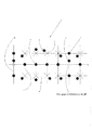
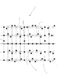
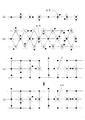
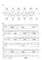
- FIG. 1 is an explanatory view showing an example of a dot pattern of the present invention
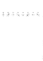
- FIG. 2 is an enlarged view showing an example of information display of the dot pattern and a bit display of data defined therein.
- the information input / output method using the dot pattern according to the present invention comprises a means for recognizing the dot pattern 1, outputting information from the dot pattern 1, and executing a program.
- the dot pattern 1 formed in an area to which information is to be given (for example, a real line formed on the medium) is captured as image data by the optical reading means, the reference dots 4 are first extracted, and these reference dots 4 are connected.
- the line be the first virtual reference line 6. If no dot is placed on the first virtual reference line 6 at the position where the reference dot 4 should originally be, a dot around the position where the reference dot 4 should be placed is extracted, and this is used as a key. Let it be dot 2 (both ends of a set of constant information).
- a reference line 9 is set, and an intersection of the virtual reference lines is set as a virtual reference point 5. Then, the dots around the virtual reference point 5 are searched, and the information dot 3 whose information is defined by the distance and direction from the virtual reference point 5 is extracted.
- the reference dots 4 are placed on the first virtual reference point 6. It is possible to set a square having a length-to-width ratio of 1 to 1 as a vertex and to derive the position by complementing the position of the virtual reference point 5.
- the ratio of length to width can be arbitrarily determined.
- the direction of the certain information group that is, the direction of the dot pattern 1 is determined by the direction of the key dot 2 from the first virtual reference line 6.
- the information dot 3 in the set of constant information may be recognized with the direction as the normal position.
- the direction of the dot pattern 1 can also be defined by the distance between the side dot 12 and the key dot 2.
- the direction is regarded as the normal position. What is necessary is just to recognize the information dot 3 in the group of fixed information.
- the central processing unit (CPU) of the optical reading unit analyzes the dot of the frame buffer, and the virtual reference of each information dot 3 A numerical value defined for each information dot 3 by the distance and direction from the point 5 (see FIGS. 2, 3, and 4) is decoded.
- These numerical values are collated with the information stored in the memory of the optical reading means or personal computer as XYZ coordinates or code values, and read by voice, image, moving image, character, program, etc. corresponding to the XYZ coordinates or code values. And output from the display means and the sound / image output means.
- the dot pattern 1 is generated by using a dot code generation algorithm to define fine dots, that is, key dots 2, information dots 3, reference dots 4, and side dots 12, in order to recognize information such as voice.
- a dot code generation algorithm to define fine dots, that is, key dots 2, information dots 3, reference dots 4, and side dots 12, in order to recognize information such as voice.
- a horizontal straight line constituting a set of constant information of a dot pattern 1 formed along reference dots 4 (in the illustrated example, a straight line) arranged in a line is defined as a first virtual line.
- a reference line 6 is provided on the medium.
- side dots 12 are provided on a third virtual reference line 8 perpendicular to the first virtual reference line 6 passing through the reference dot 4 (reference dot arranged as the key dot 2 in the illustrated example).
- a straight line parallel to the third virtual reference line 8 passing through the reference dot 4 is defined as a second virtual reference line 7, and a straight line parallel to the first virtual reference line 6 passing through the side dot 12 is defined as the first virtual reference line 7.
- Four virtual reference lines 9 are assumed.
- the dot is determined by the direction in which the key dot 2 arranged at a predetermined position on the medium (on the third virtual reference line 8 in the illustrated example) is shifted from the first virtual reference line 6 and the distance from the side dot 12.
- the pattern direction is defined, and a set of constant information of the dot pattern 1 is defined from the arrangement interval of the side dots 12 and / or the key dots 2.
- the dot pattern 1 can be formed along a real line visibly formed on the surface of the medium.
- the real line here is a concept with respect to a virtual line, and is an actually existing line. All of these are included.
- a solid line, a broken line, a dotted line, a straight line, a curved line, and the like can be given. Absent.
- the dot pattern may be unevenness such as printing, display display, or a hole or groove on a metal or plastic.
- intersection of the second virtual reference line 7 and the fourth virtual reference line 9 is defined as a virtual reference point 5.
- the dot pattern 1 is generated by arranging one or a plurality of information dots 3 having a distance and a direction based on the virtual reference point 5 set in this way.
- the image data obtained by capturing the dot pattern 1 with the optical reading unit corrects distortion caused by the optical reading unit and / or distortion caused by imaging from an oblique direction. Even when the image is taken obliquely by a popular camera with a lens having a high distortion rate, it can be accurately recognized when the image data of the dot pattern 1 is captured. Even when the optical reading means is tilted with respect to the surface of the dot pattern 1, the dot pattern 1 can be accurately recognized by a predetermined algorithm.
- the key dots 2 are dots arranged at both ends of a set of fixed information as shown in FIG.
- the key dot 2 is a representative point of the dot pattern 1 for one region representing a group of information dots.
- the representative point may be arranged anywhere in the group of information dots. For example, if the interval between adjacent reference dots is 0.5 mm, the reference dot 4 at the end of the area of the dot pattern 1 is arranged at a position shifted by 0.1 mm upward from the position where it should originally be arranged. . Therefore, when the information dot 3 is defined by the X and Y coordinate values from the reference dot 4, the position at a distance of 0.1 mm below the key dot 2 is the coordinate point.
- this numerical value (0.1 mm) is not limited to this, and can be varied according to the size of the area of the dot pattern 1.
- Information dot 3 is a dot for recognizing various information.
- This information dot 3 is arranged at the end point represented by a vector with the virtual reference point 5 as the start point. For example, as shown in FIG. 2, the information dot 3 is rotated by 45 degrees in the clockwise direction because a dot 0.1 mm away from the virtual reference point 5 has a direction and a length expressed by a vector. These are arranged in 8 directions to represent 3 bits.
- 3 bits are expressed by arranging in 8 directions, but the present invention is not limited to this, and 4 bits can be expressed by arranging in 16 directions. Of course, it can be arranged in length.
- the information dot 3 is arranged at the end position at the virtual reference point 5 starting from the virtual reference point 5, but the dot is arranged on the virtual reference point without being limited thereto.
- Information may be defined depending on whether or not it is present. For example, information can be defined as “1” if a dot is arranged on a virtual reference point, and “0” if no dot is arranged.
- the dot diameters of the key dot 2, information dot 3, reference dot 4, and side dot 12 are 0.03 or more in consideration of appearance, printing accuracy with respect to paper quality, resolution of the optical reading means and optimum calculation speed. About 0.05 mm is desirable. However, as the technology advances and the printing accuracy, the resolution of the optical reading means, and the optimum calculation speed improve, it goes without saying that the dot diameter approaches zero as much as possible.
- the dot diameter and the arrangement interval may be appropriately determined based on the resolution of the optical reading means and the optimum calculation speed.
- the interval between the reference point dots 4 is preferably about 0.3 to 0.5 mm. Needless to say, this interval approaches zero as long as the technology advances and the printing accuracy, the resolution of the optical reading means, and the optimum calculation speed improve.
- the shift of the key dot 2 is preferably about 20% of the interval between the reference dots 4.
- the distance between the information dot 3 and the virtual reference point 5 is preferably about 15 to 30% of the distance between the adjacent virtual reference points 5. This is because if the distance between the information dot 3 and the virtual reference point 5 is shorter than this distance, the dots are easily recognized as a large lump and become unsightly as the dot pattern 1. On the contrary, if the distance between the information dot 3 and the virtual reference point 5 is longer than this distance, it is determined whether the information dot 3 has the vector direction around one of the adjacent virtual reference points 5. This is because it becomes difficult.
- the dot pattern according to the present invention is read by an optical reading means (for example, a camera or a scanner), and the dot pattern of a predetermined position, a predetermined region, or the entire region is read by being brought into contact with or separated from the medium surface, or formed in a linear shape. This is done by tracing and reading the dot pattern.
- an optical reading means for example, a camera or a scanner
- the information is defined in a sufficiently long dot pattern, it is possible to define a large amount of information.
- the information is read by tracing the area on the medium surface where the dot pattern is formed.
- trace information along a line that draws a figure or figure that is visually formed on the surface of the medium reads information, traces along the outline of a photograph or image frame, or the outline of an object in the photograph or image, and information Read. It is also possible to read information by tracing along a character string on the surface of the medium.
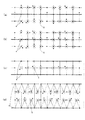
- FIG. 3 shows an example of the information dot and the bit display of the data defined therein, which shows another form.
- the information dot 3 if two types of short (upper part in FIG. 3) and long (lower part in FIG. 3) are used from the virtual reference point 5 derived from the reference dot 4 and the vector direction is eight directions, then 4 bits. Can be expressed. At this time, it is desirable that the longer one is about 25 to 30% of the distance between adjacent virtual reference points 5, and the shorter one is about 15 to 20%. However, it is desirable that the center interval between the long and short information dots 3 is longer than the diameter of these dots.
- the information dot 3 is preferably one dot in consideration of its appearance. However, if the appearance is ignored and the amount of information is to be increased, a large amount of information can be obtained by assigning 1 bit to each vector and expressing the information dot 3 with a plurality of dots.
- an information dot 3 defined from the reference dots 4 can represent information of 2 8, and 2 64 in chunks of the information dot eight constant information 1.
- FIG. 4 shows an example of information dot 3 and bit display of data defined therein.
- (A) shows two dots
- (b) shows four dots
- (c) shows five dots. Is shown.
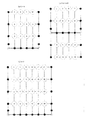
- FIG. 5 shows a modification of the dot pattern.
- (A) shows 12 information dots 3 arranged in the area,
- (b) shows 16 information dots 3 arranged, and
- (c) shows information. 24 dots 3 are arranged.
- the above-described dot pattern 1 shown in FIG. 1 shows an example in which eight information dots 3 are arranged in a set of constant information.
- the information dots 3 are not limited to being arranged in a set of constant information, and can be variously changed.
- twelve information dots 3 are arranged in a set of fixed information according to the amount of information required or the resolution of the optical reading means (FIG. 5A), and the information dots 3 are set in a set of fixed information.
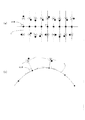
- 6 and 7 sequentially show an example of a process for forming a stream dot pattern.
- the dot pattern according to the present invention is different from the conventional dot pattern.
- step 1 corresponding to the visible information on the surface of the medium, the reference dot 4 is continuously arranged in a line at a place where information is input / output. Place multiple.
- the reference dots 4 are arranged in a curved shape.
- the arrangement of the reference dots 4 is not limited to this, and is composed of a plurality of line segments interwoven with straight lines and curves.
- Various modifications can be made to form the dot pattern in a shape that matches the area where information is input and output, such as a polygonal line.
- reference dots 4 may be arranged on the actual lines that are visually formed on the medium surface, or the reference dots 4 may be arranged according to a predetermined rule along the actual lines.
- the reference dots are not limited to this, and a plurality of intervals are mixed to define a set of constant information of the dot pattern, It is also possible to define both a set of constant information of a dot pattern and a direction of the dot pattern by arrangement intervals of three different reference dots in the set of fixed information.
- a first virtual reference line 6 that connects the reference dots 4 arranged in a line is provided.
- the first virtual reference line 6 is provided by a curve, but the first virtual reference line 6 is not limited to this, and for the reference dots 4 arranged in a curved line.
- the straight first virtual reference line 6 may be provided, or the curved first virtual reference line 6 may be provided for the reference dots 4 arranged in a straight line as shown in FIG. . That is, the second virtual reference line 7, the virtual reference point 5, and the information dot 3 in Step 3 to Step 5 to be described later are arranged according to the positions where the reference dots are connected to form a first line composed of a straight line, a broken line, and / or a curve.
- One virtual reference line 6 can be freely defined.
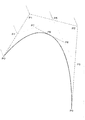
- the first virtual reference line 6 in the case of a curve is preferably a Bezier curve.
- reference dots on the first virtual reference line are P0 and P3, and P1 and P2 are given control points.
- points P4, P5, and P6 are obtained by dividing the three line segments P0-P1, P1-P2, and P2-P3 obtained by connecting the control points in order at a one-to-one ratio.
- points P7 and P8 are obtained by dividing the two line segments P4-P5 and P5-P6 obtained by connecting these points in order at a one-to-one ratio.
- the first virtual reference line 6 may be provided using various algorithms such as a spline curve obtained by using a spline function, an nth order polynomial, an elliptic arc, and the like, not limited to a Bezier curve.
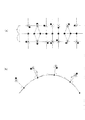
- a second virtual reference line 7 defined at a predetermined position from the reference dots 4 and / or the first virtual reference line 6 arranged in a line is provided.
- the second virtual reference line 7 is arranged adjacent to the reference dot 4 adjacent to a predetermined position on the vertical line with respect to the tangent line of the first virtual reference line 6 at the midpoint between the adjacent reference dots 4.
- the second virtual reference line 7 is not limited to this, and a virtual reference point is provided in accordance with an area in which information is input / output by a dot pattern, as will be described later.
- it can be defined by various methods.
- the second virtual reference line 7 may be provided only on one side with respect to the first virtual reference line 6 to define the direction of the dot pattern, or may be provided on both sides to increase the amount of information. .
- a plurality of virtual reference points 5 are provided at predetermined positions on the second virtual reference line 7.
- the virtual reference point 5 is an isosceles triangle whose bottom is the intersection of the second virtual reference lines 7, that is, the straight line connecting the adjacent reference dots 4, and the second virtual reference line 7 is the opposite side.
- the position of the virtual reference point 5 is not limited to this, and it is provided at the midpoint of the second virtual reference line 7 or instead of the second virtual reference line 7.
- Various modifications such as provision on the dots 4 are possible.
- step 5 the information dot 3 is arranged at the end point expressed by a vector with the virtual reference point 5 as the start point.
- one information dot 3 is arranged for one virtual reference point 5 so that the vector direction from the virtual reference point 5 is eight directions and the distance from the virtual reference point 5 is equal.
- the arrangement of the information dots 3 is not limited to this, and the information dots 3 are arranged on the virtual reference point 5, the vector directions are arranged in 16 directions, or two are arranged for one virtual reference point 5. It is possible to arrange a plurality of elements in any direction and in any length.
- the stream dot pattern according to the present invention is continuous with a line including a curve unlike the reference dot formed in a two-dimensional lattice pattern in the conventional dot pattern proposed by the present inventor. Are formed based on the reference dots arranged in this manner.
- the dot pattern is not limited by the shape of the rectangular area formed as a two-dimensional code, and is a dot pattern formed by a set of free-form constant information matched to the information area visually formed on the medium surface. Can be formed.
- the virtual reference line and the virtual reference point according to the present invention are not actually printed and formed on the surface of the medium, but only when the dot pattern is arranged on the image memory of the computer or when the dot pattern is read. Is set virtually.
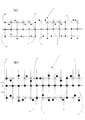
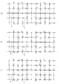
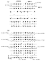
- FIG. 9A is a diagram showing an example of a dot pattern used in the present invention.
- the set of constant information of the dot pattern 1 is the first virtual reference line 6, the reference dot 4, the second virtual reference line 7, the virtual reference point 5, the information dot 3, the first dot. 3 virtual reference lines 8, side dots 12, and a fourth virtual reference line 9.
- a set of constant information of the dot pattern 1 is defined by the side dots 12 arranged on the third virtual reference line 8. Further, the direction of the dot pattern 1 is arranged only in the x direction from the virtual reference point 5 in the information dot 3 positioned in the + Y direction (upward), and in the information dot 3 positioned in the ⁇ Y direction (downward). Is defined by being arranged only in the + direction from the virtual reference point 5.
- a set of constant information is defined by the arrangement of the side dots 12 at predetermined intervals, and an information dot 3 whose deviation direction from the virtual reference point 5 is the x direction appears above the first virtual reference line 6.
- the direction of the dot pattern is upward, and when the information dot 3 in the + direction appears, the direction of the dot pattern is downward.
- the direction of the dot pattern is upward when there are three information dots whose deviation direction is the + direction in a set of constant information, and the direction of the dot pattern is downward when there are two information dots.
- the direction of the dot pattern Is upward, and when the information dots are arranged in all areas and are not arranged on the virtual reference point and arranged at a predetermined distance, the direction of the dot pattern is downward.
- the like can be considered to be to be the Ki.
- FIG. 9B is a diagram showing an example of a dot pattern used in the present invention.
- the set of constant information of the dot pattern 1 is the first virtual reference line 6, the reference dot 4, the second virtual reference line 7, the virtual reference point 5, the information dot 3, the first dot. 3 virtual reference lines 8, side dots 12, and a fourth virtual reference line 9.
- a set of constant information of the dot pattern 1 is defined by the side dots 12 arranged on the third virtual reference line 8. Furthermore, the direction of the dot pattern 1 is defined by making the intervals H1 and H2 between the first virtual reference line 6 (or the reference dot 4) and the side dots 12 different in the vertical direction across the first virtual reference line 6. Is done.
- a group of constant information is defined by the side dots 12, and the distance between the reference dot 4 and the side dot 12 is shorter (H1) above and below the first virtual reference line 6. If the dot pattern 1 is upward, the dot pattern 1 is upward, and if the longer (H2) is upward, the dot pattern 1 is downward. Even if the image is taken from the direction of the dot pattern, it is possible to recognize the direction of the dot pattern by converting the image data by an algorithm.
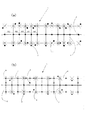
- FIG. 10A is a diagram showing an example of a dot pattern used in the present invention.
- a set of constant information of the dot pattern 1 is composed of a first virtual reference line 6, a reference dot 4, a second virtual reference line 7, a virtual reference point 5, and an information dot 3. Is done.
- a set of constant information of the dot pattern 1 is defined by an arrangement interval of a plurality of reference dots 4 provided on the first virtual reference line 6. Further, the direction of the dot pattern 1 is shifted downward in the upper and lower sides across the first virtual reference line 6 with respect to the shift direction of the information dot 3 from the virtual reference point 5 located at the leftmost position of the set of constant information. Defined by
- the region where the interval between the reference dots 4 is the largest is the leftmost of the group of constant information, and the direction of deviation of the information dot 3 from the virtual reference point 5 located at the leftmost of the group of constant information is the first virtual It can be seen that the dot pattern 1 is upward when the upper and lower sides across the reference line 6 are downward, and the dot pattern 1 is downward when it is upward.
- side dots are further arranged, the number of information dots is varied, and the area of the area is varied up and down with respect to the first virtual reference line, complementing them to recognize the direction of the dot pattern May improve the accuracy.
- FIG. 10B is a diagram showing an example of a dot pattern used in the present invention.
- the set of constant information of the dot pattern 1 is the first virtual reference line 6, the reference dot 4, the second virtual reference line 7, the virtual reference point 5, the information dot 3, and the side.
- a dot 12, a third virtual reference line 8, and a fourth virtual reference line 9 are included.
- a set of constant information of the dot pattern 1 is defined by the key dots 2 arranged so as to be shifted from the first virtual reference line 6. Further, the direction of the dot pattern 1 is that the key dots 2 are arranged in the + Y direction with respect to the first virtual reference line 6 and that the side dots 12 in the + Y direction are closer to the side dots 12 in the ⁇ Y direction. Since the distance is shorter, it can be seen that the direction is positive and the dot pattern 1 is upward.
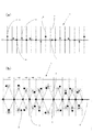
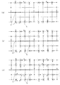
- FIG. 11A is a diagram showing an example of a dot pattern used in the present invention.
- the set of constant information of the dot pattern 1 is the first virtual reference line 6, the reference dot 4, the second virtual reference line 7, the virtual reference point 5, the information dot 3, the first dot. 3 virtual reference lines 8, side dots 12, and a fourth virtual reference line 9.
- a set of constant information of the dot pattern 1 is defined by the side dots 12 arranged on the third virtual reference line 8. Furthermore, the direction of the dot pattern 1 is such that two information dots 3 whose information is defined by the distance and direction from the virtual reference point 5 are arranged in the information dot 3 positioned in the upward direction, and in the downward direction, By arranging one information dot 3, the direction of the dot pattern is defined.
- the information dot 3 in a set of constant information is recognized with the direction being the normal position, and the number of information dots 3 is one in the + Y direction. If they are arranged, the information dots 3 in the set of fixed information may be recognized with the set of the fixed information rotated in the direction rotated 180 degrees around the center as the normal position.
- the direction of the dot pattern may be defined by varying the distance (shift width) of the information dot from the virtual reference point on the top and bottom with respect to the first virtual reference line.
- a set of constant information of the dot pattern may be defined by changing the number of information dots in either the upper or lower reference.
- the distance from the virtual reference point is 0, that is, an information dot is arranged on the virtual reference point so as to be adopted as a part of the virtual reference point located below the first virtual reference line. Information may be defined.
- the location where the information dots are arranged on the virtual reference point appears only on the top or the bottom of the first virtual reference line, it is possible to define the unit and direction of the dot pattern in a certain direction. Good.
- FIG. 11B is a diagram showing an example of a dot pattern used in the present invention.
- the set of constant information of the dot pattern 1 is the first virtual reference line 6, the reference dot 4, the second virtual reference line 7, the virtual reference point 5, the information dot 3, and the third virtual reference line.
- the reference line 8, the side dots 12, and the fourth virtual reference line 9 are included.
- a set of constant information of the dot pattern 1 is defined by the side dots 12 arranged on the third virtual reference line 8. Furthermore, the direction of the dot pattern 1 is defined by providing an information dot arrangement region only either above or below the first virtual reference line 6.
- the dot pattern is downward and the dot pattern 1 is upward when the information dots 3 and the side dots 12 are arranged only in the downward direction.
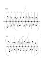
- FIG. 12 (a) is a diagram showing an example of a dot pattern used in the present invention.
- the set of constant information of the dot pattern 1 includes the first virtual reference line 6, the reference dot 4, the second virtual reference line 7, the virtual reference point 5, the information dot 3, and the key. Consists of dots 2.
- the direction of the dot pattern 1 and the set of constant information are defined by the key dot 2. That is, when the key dot 2 is arranged in the upper direction of the first virtual reference line 6, it can be seen that the dot pattern 1 is upward, and when the key dot 12 is arranged in the lower direction, the dot pattern It can be seen that 1 is downward.
- a set of constant information can be seen by the key dots 2 arranged at predetermined intervals.
- the illustrated example also shows an example of forming a dot pattern in which the virtual reference point 5 is defined as an intermediate point between adjacent reference dots 4 and the width of the stream is particularly small. It is possible to have it.
- FIG. 12B is a diagram showing an example of a dot pattern used in the present invention.
- the set of constant information of the dot pattern 1 is composed of the first virtual reference line 6, the reference dot 4, the second virtual reference line 7, the virtual reference point 5, and the information dot 3. Is done.
- a set of constant information of the dot pattern 1 is defined by an arrangement interval of a plurality of reference dots 4 provided on the first virtual reference line. Furthermore, the direction of the dot pattern 1 is defined by providing the arrangement intervals of the reference dots 4 in three stages.
- the arrangement interval of the reference dots 4 is repeated according to a predetermined rule of large, medium, and small, thereby defining a set of constant information, and the reference dots are arranged in the order of large, medium, and small from the -X direction to the + X direction. If the interval of 4 is repeated, it recognizes that the direction of the dot pattern is upward with the direction being the normal position, and if it is repeated from the + X direction to the ⁇ X direction, It can be seen that the direction obtained by rotating the cluster 180 degrees around the center is the normal position, and the direction of the dot pattern is downward.
- FIG. 13 (a) is a diagram showing an example of a dot pattern used in the present invention.
- the set of constant information of the dot pattern 1 is composed of the first virtual reference line 6, the reference dot 4, the second virtual reference line 7, the virtual reference point 5, and the information dot 3. Is done.
- a set of constant information of the dot pattern 1 is defined by an arrangement interval of a plurality of reference dots 4 provided on the first virtual reference line 6. Further, the direction of the dot pattern 1 is such that the direction of deviation of the information dot 3 from the virtual reference point 5 located at the leftmost position of the set of constant information is different on each side opposite to the first virtual reference line. Is defined by
- the region where the interval between the reference dots 4 is the largest is the leftmost of the set of constant information, and the information dot 3 from the virtual reference point 5 located at the leftmost of the set of constant information is the first virtual reference line 6.
- the number of information dots may be varied, or the area of the region may be varied up and down with respect to the first virtual reference line, and complemented thereby to improve the accuracy of the recognition of the direction of the dot pattern.
- the number of information dots may be varied, or the area of the region may be varied up and down with respect to the first virtual reference line, and complemented thereby to improve the accuracy of the recognition of the direction of the dot pattern.
- FIG. 13B is a diagram showing an example of a dot pattern used in the present invention.
- the fixed information group of the dot pattern 1 is composed of the first virtual reference line 6, the reference dot 4, the second virtual reference line 7, the virtual reference point 5, and the information dot 3. Is done.
- the set of constant information of the dot pattern 1 is defined by the direction of displacement of the information dot 3 from the virtual reference point 5, and the direction of the dot pattern 1 is the direction of displacement of the information dot 3 from the virtual reference point 5 as the first direction. It is defined by making it different up and down with respect to the virtual reference line 6.
- the area where the information dot 3 is shifted in the x direction in the upward direction with respect to the first virtual reference line 6 and is shifted in the + direction in the downward direction is the leftmost end of a set of constant information.
- the information dot 3 with a predetermined period (regularity such as the +++++ direction in the upward direction and the + xxx direction in the downward direction with respect to the first virtual reference line 6).
- a set of constant information is defined by shifting from the virtual reference point 5, and from the ⁇ X direction to the + X direction, the upper direction with respect to the first virtual reference line 6 is the +++++ direction, and the lower direction is + XXX.
- FIG. 14 is a diagram showing an example of a dot pattern used in the present invention.
- the set of constant information of the dot pattern 1 is the first virtual reference line 6, the reference dot 4, the second virtual reference line 7, the virtual reference point 5, the information dot 3, and the third virtual reference line.
- a reference line 8, key dots 2, side dots 12, and a fourth virtual reference line 9 are included.
- the deviation of the information dot 3 from the virtual reference point 5 (the distance from the virtual reference point to the information dot) is different between the x direction and the + direction.
- the direction of displacement but also the length from the information dot to the virtual reference point can be determined, and the information dot can be recognized accurately.
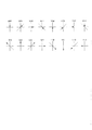
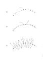
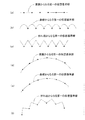
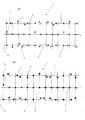
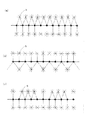
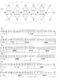
- FIG. 15 is a diagram showing an example of defining the first virtual reference line from the arrangement of the reference dots.
- FIG. 15A shows an example in which the reference dots are arranged in a straight line and the first virtual reference line is provided in a straight line
- FIG. 15B shows the reference dots arranged in a straight line
- FIG. 15C shows an example in which the first virtual reference line is provided in a curved line
- FIG. 15C shows an example in which the reference dots are arranged in a straight line and the first virtual reference line is provided as a broken line
- 15 (d) shows an example in which the reference dots are arranged in a curved line and the first virtual reference line is provided in a straight line
- FIG. 15 (e) shows the reference dots arranged in a curved line
- FIG. 15F illustrates an example in which the first virtual reference line is provided as a curve
- FIG. 15F illustrates an example in which the reference dots are arranged in a curved line and the first virtual reference line is provided as a broken line. It is.
- the first virtual reference line is provided as a broken line
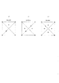
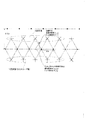
- FIG. 16 shows a second virtual defined from a plurality of reference dots and / or a first virtual reference line to form a triangle having a first virtual reference line that connects adjacent reference dots with a straight line as a base. It is a figure explaining the method of defining a reference line.
- the second virtual reference line 7 constituting the triangle is defined from the distance P between adjacent reference dots. That is, the height of the triangle is determined at a predetermined magnification of the reference dot interval, and the second virtual reference line 7 is provided so as to intersect on an intermediate point between adjacent reference dots.
- the height of the triangle is configured to be twice the distance P between adjacent reference dots, but the height of the triangle is not limited to this, and various changes can be made. is there.
- the second virtual reference line 7 constituting the triangle is defined from the distance P between adjacent reference dots. That is, the length of the opposite side of the triangle is determined at a predetermined magnification of the reference dot interval, and the second virtual reference line 7 is provided so as to intersect on an intermediate point between adjacent reference dots.
- the opposite side of the triangle is configured with a length twice the distance P between adjacent reference dots, but the length of the opposite side of the triangle is not limited to this, and various changes are possible. It is.
- the second virtual reference line 7 constituting the triangle is defined from the base angle ⁇ of the triangle. That is, in order to provide a virtual reference point at an arbitrary position on the medium surface, the value of the base angle of the triangle is determined in advance, and the second virtual reference line 7 is provided so as to constitute the determined base angle.
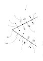
- FIG. 17 is a diagram illustrating a method of defining a second virtual reference line from the first virtual reference line and / or a plurality of reference dots when the first virtual reference line is configured by a curve. .
- an angle for providing the second virtual reference line with respect to the tangent line of the first virtual reference line is determined in advance.
- the example in which the 2nd virtual reference line 7 is provided so that the defined angle may be comprised is shown.
- the second virtual reference line 7 is defined from the length Q of the first virtual reference line composed of a curve connecting adjacent reference dots. That is, the height from the tangent line of the first virtual reference line is determined at a predetermined magnification of the length, and the second virtual reference line 7 is formed from adjacent reference dots so as to intersect at a position corresponding to the height. Provided.
- the height from the tangent line of the first virtual reference line is determined by a length that is one time the length Q of the first virtual reference line formed by a curve connecting adjacent reference dots.
- the height is not limited to this, and various modifications are possible, such as defining the dot pattern direction and a set of constant information by, for example, even multiples at certain points and odd multiples at other points. It is.
- the second virtual reference line 7 is defined from the length Q of the first virtual reference line formed by a curve connecting adjacent reference dots. That is, the second virtual reference line 7 is provided from the adjacent reference dots so as to have a length of a predetermined magnification of the length.
- the length of the second virtual reference line 7 is determined so as to be one time the length Q of the first virtual reference line formed by a curve connecting adjacent reference dots.
- the present invention is not limited to this, and various modifications are possible, for example, by defining the dot pattern direction and a set of constant information by making the even multiple at certain points and the odd multiple at other points.
- FIGS. 17A to 17C can be used in appropriate combination, and a straight line perpendicular to the tangent at the midpoint of the first virtual reference line made of a curve is defined, and the above-described method is used.
- a second virtual reference line or a virtual reference point may be defined in combination.
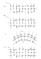
- FIG. 18A is a diagram illustrating an example of a method for defining the second virtual reference line when the first virtual reference line is configured by a broken line.
- the second virtual reference line 7 is a straight line that bisects the interior angle at the apex formed by the first virtual reference line 6. Is desirable.
- FIG. 18B and FIG. 18B are diagrams showing an example in which reference dots are always arranged at the vertices of the first virtual reference line.
- the first virtual reference line is a virtual line composed of a straight line, a broken line, and / or a curve connecting a plurality of reference dots
- various processes in addition to the reference dot are performed as shown in FIGS.
- the virtual reference line is preferably the apex of the first virtual reference line only at the location where the reference dot is arranged.
- FIG. 19 is a diagram illustrating an example of a method for defining the second virtual reference line.
- FIG. 19 (a) shows an intermediate point between adjacent reference dots
- FIG. 19 (b) shows an example in which the second virtual reference line 7 is provided on the reference dot.
- FIG. 20 is a diagram illustrating an example in which the second virtual reference line 7 is provided perpendicular to the first virtual reference line made of a straight line or perpendicular to the tangent line of the first virtual reference line made of a curve. .
- FIG. 21 shows that a plurality of virtual reference points provided at predetermined positions on the second virtual reference line have a constant distance from the tangent line of the first virtual reference line formed of a straight line or the curve of the first virtual reference line. It is a figure which shows the example provided so that it may become.
- FIG. 22A is a diagram showing an example in which the shape of a dot itself is formed instead of a polygonal shape whose direction can be defined from a normal round shape, and the direction of the dot pattern 1 is defined by the difference in the shape. .
- FIG. 22A shows an example in which dots are formed in a triangular shape, in any direction from one side constituting a triangle parallel to the first virtual reference line 6 or the fourth virtual reference line 9.
- the triangular dots may be recognized with the direction as the normal position
- the direction of the dot pattern is defined by various methods such as setting the direction to the normal position of the dot pattern 1 Is possible.
- FIG. 22B is a diagram showing an example in which normal round dots and polygon dots are mixed.
- the direction of the dot pattern 1 cannot be defined.
- the direction of the dot pattern 1 can be defined by using it in combination with the side dots 12 and the key dots 2. Is possible.
- normal round dots are arranged as reference dots 4 and key dots 2
- polygonal dots whose orientation can be defined are arranged as information dots 3 and side dots 12, and are not limited to reference dots and information dots.
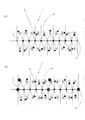
- 23 (a) and 23 (b) are diagrams illustrating an example of defining a dot pattern direction and a set of constant information by appropriately changing the size of the dot itself.
- FIG. 23A defines a set of constant information of the dot pattern 1 and the direction of the dot pattern 1 by using a triangular dot having a different size from other dots as one of the plurality of reference dots 4.
- a round dot having a size different from that of other dots is arranged as a reference dot 4 in order to define a set of constant information, and other information dots 3 are arranged only in the + Y direction.
- the direction of the dot pattern 1 is defined by arranging information dots 3 having different sizes.
- the method of defining a set of constant information and the direction of a dot pattern by changing the size and shape of the dots shown in FIGS. 22 to 23 includes various algorithms such as an algorithm for generating and analyzing the dot pattern, and the accuracy of the reading device. Of course, the size and shape of some or all of the dots may be appropriately changed according to the situation.
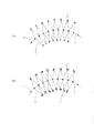
- FIG. 24 is a diagram showing an example in which the direction of the dot pattern and a set of constant information of the dot pattern are defined by making the number of virtual reference points different on both sides across the first virtual reference line. is there.
- a second virtual reference line is provided at a predetermined angle from an adjacent reference dot so as to intersect on a vertical line at an intermediate point between adjacent reference dots.
- a virtual reference point 5 is arranged on the reference line.
- a second virtual reference line is provided so as to pass through the reference dot and perpendicularly intersect the first virtual reference line.
- a virtual reference point 5 is arranged on the virtual reference line.
- the virtual reference point 5 is defined by at least two reference dots, and the number is smaller than the virtual reference point 5 provided on the opposite side across the first virtual reference line.
- the direction of the dot pattern can be defined with the direction as the normal position.
- the virtual reference point 5 (the number of which is smaller than the opposite side) appears in the ⁇ Y direction from the first virtual reference line, the direction in which the dot pattern is rotated by 180 degrees about the center is the normal position.
- the direction of the dot pattern can be defined as
- FIG. 24B one virtual reference point 5 is provided for one reference dot in the + Y direction with respect to the first virtual reference line, and three reference dots are provided in the -Y direction.
- FIG. 24 (c) shows a modification example in which one virtual reference point 5 is provided on each side across the first virtual reference line for one reference dot.
- the location is defined as a point defining a set of constant information of the dot pattern, and the number of virtual reference points 5 in the set of constant information is varied up and down with respect to the first virtual reference line (in the + Y direction, It is a figure which shows the example which defines the direction of a dot pattern by three virtual reference points 5 in a set of fixed information, and in the -Y direction, four virtual reference points in a set of fixed information) .
- the definition method of the virtual reference point may be changed as appropriate in a set of constant information, and the position where the virtual reference point is provided according to the visible information on the medium surface is determined. It is also possible to adjust.
- FIG. 25 is a diagram showing an example of a dot pattern formed along a polygonal line.
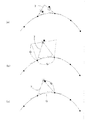
- FIG. 26 is a diagram showing an arrangement example of key dots according to the present invention.
- FIG. 26A out of a plurality of reference dots arranged in a line, one reference dot is arranged obliquely from the first virtual reference line, and the direction of the dot pattern and a set of constant information are collected. Is defined.
- the reference dot is not arranged at the position where the dot pattern should be originally arranged, and the key dot 2 is arranged in the periphery, in the illustrated example, in the upper left direction from the position where it should be arranged.
- the direction of the dot pattern is defined by recognizing the dot pattern with the direction as the normal position when the key dot 2 is arranged in the shift direction.
- the key dots 2 arranged on the medium surface are arranged in a parallel direction with respect to the direction of the second virtual reference line. They are arranged in the vertical direction to define a set of constant information and the direction of the dot pattern.
- the arrangement of constant information and the direction of the dot pattern are defined by being arranged in the + Y direction in a direction parallel to the direction of the second virtual reference line.
- the key dot 2 on the right side of the example the key dot 2 is arranged in a direction perpendicular to the second virtual reference line to define a set of constant information, and the key is shifted in the + X direction from the position where the reference dot should originally be arranged. Since the dots 2 are arranged, the direction of the dot pattern can be defined by recognizing the direction as the normal position.
- the key dots 2 arranged on the medium surface are arranged at predetermined positions on the third virtual reference line to define a set of constant information and the direction of the dot pattern.
- a group of constant information is defined by arranging key dots 2 on a third virtual reference line that is a straight line perpendicular to the tangent line of the curve forming the first virtual reference line, and the first virtual reference
- FIG. 26 (d) shows an example in which the second virtual reference line is defined only from reference dots other than the reference dots arranged so as to be shifted as key dots.
- the second virtual reference line is not defined from the reference dot before being arranged as the left key dot 2 in the illustrated example, and the second virtual reference line is not defined from the reference dot before being arranged as the right key dot 2 in the illustrated example.
- a virtual reference line is defined.
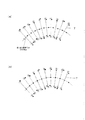
- FIG. 27 is a diagram for explaining an arrangement example of side dots according to the present invention.
- side dots 12 are arranged on a third virtual reference line passing through the reference dots to define a set of constant information and the direction of the dot pattern.
- a set of constant information is defined by adding more dots while maintaining the arrangement of the reference dots, and the side is only one of the top and bottom with respect to the first virtual reference line.
- FIG. 27B shows an example in which a fourth virtual reference line which is a straight line parallel to the first virtual reference line passing through the side dots 12 is provided, and virtual reference points are provided at predetermined intervals on the fourth virtual reference line. It is possible to improve the reading accuracy by defining the virtual reference point by both the second virtual reference line and the fourth virtual reference line.
- FIG. 27 (c) defines a set of constant information and the direction of the dot pattern by arranging side dots 12 at different distances from the first virtual reference line on both sides of the first virtual reference line.
- FIG. 27 (d) is a diagram showing an example in which the key dots arranged by shifting the reference dots on the third virtual reference line and the both sides sandwiching the first virtual reference line are shown in FIG. An example is shown in which the direction of the dot pattern is defined by the distance between the side dots 12 and the key dots arranged at the same distance from one virtual reference line, and a set of constant information is defined by the distance between the side dots 12 and the key dots.
- FIG. 27 (d) is a diagram showing an example in which the key dots arranged by shifting the reference dots on the third virtual reference line and the both sides sandwiching the first virtual reference line are shown in FIG.
- An example is shown in which the direction of the dot pattern is defined by the distance between the side dots 12 and the key dots arranged at the same distance from one virtual reference line, and a set of constant information
- FIG. 28 is a diagram illustrating an example of obtaining the center XY coordinate value obtained by imaging the dot pattern by the optical reading unit.
- the coordinate value of the coordinate center of the dot pattern is obtained.
- the representative point coordinate value of the dot pattern in which one coordinate value is defined is (X 0 , Y 0 ) in the dot coordinate system and (x 0 , y 0 ) in the imaging coordinate system.
- the increment value of the X coordinate value of the dot coordinates is Kx and the increment value of the Y coordinate value is Ky
- the coordinate values adjacent to (X n , Y n ) are (X n + 1 , Y n).
- the value of +1 ) can be expressed as the following equation. Therefore, the XY coordinate value of the imaging center is expressed by the following formula.
- n is the number of reference dots from the beginning of a plurality of reference dots that define a set of coordinate values to the beginning of the reference dot that is defined by the coordinate values that are successively arranged next.
- ⁇ is a coefficient for indicating the increment value of the imaging coordinate system y coordinate with respect to the distance ⁇ x between the reference dots of the imaging coordinate system of the dot pattern, that is, ⁇ x is the increment value of the dot coordinate system Y coordinate.
- ⁇ x is the increment value of the dot coordinate system Y coordinate.
- a code value may be defined in the area where the Y coordinate value is defined.
- a Z coordinate value can also be defined, whereby a three-dimensional coordinate can be expressed.
- the height can be read at any position on the map, and further, if dots are printed on the surface of the solid, the shape of the solid can be read and reproduced.
- Ink used for dot printing of stream dot pattern is stealth ink (invisible ink) that absorbs infrared rays or carbon black, and ink used for normal graphic and text printing is non-carbon ink that reflects or transmits infrared rays. Is desirable.
- the dot pattern is composed of extremely small dots with a diameter of 0.04mm (about 0.05mm for inkjet printers) and is difficult to see. Using colorless and transparent infrared absorbing stealth ink developed for high-quality output makes the dots completely invisible. It is also possible to do.
- the information dot is usually provided at a position equidistant from the virtual reference point in order to make the dot inconspicuous, but if you want to express the information not only in the direction but also in the length and accurately recognize the information dot, Information may be defined by different distances for each virtual reference point.
- CMYK K carbon black
- CMY may be used for CAD drawings, characters / symbols / graphics, maps, photographs, and graphics, and dots may be printed thereon with K.
- the black color is expressed as composite black by mixing 100% of CMY.
- perfect black cannot be reproduced, black may not be emphasized and the picture may not be tightened.
- the area where dots are printed is dot-like because the dots are printed with K, and if you look closely, it will be a light grayish pattern. In order to solve this, it is only necessary to print dots only in the minimum necessary area and use CMYK in the area where dots are not printed as usual. However, the scanner can be touched only in a limited area where dots are printed.
- ink that reacts in the infrared region cannot be used for copying, security can be maintained at a high level.
- printing media regardless of the type of paper to be printed, dot printing is possible on any paper, such as art paper, matte paper, high-quality paper, plain paper, newspaper, photographic paper, printer paper, etc. Other than paper, any medium that does not expand or contract can be printed.
- a scanner that reads dot codes can process from dot pattern shooting to dot code analysis in just 0.1 to 0.2 seconds, and can access information instantly without stress.
- FIG. 29 Next, other arrangement examples of the dot pattern will be described with reference to FIGS. 29 to 31.
- FIG. 29A is a diagram illustrating an example in which the virtual reference point 5 is provided on the reference dot 4 on the first virtual reference line, not on the second virtual reference line, and FIG. It is a figure which shows the example in which the reference point 5 is provided also on the reference
- the time for searching for the second virtual reference line can be omitted, and the reading speed can be improved.
- the amount of information can be increased. Become.
- FIGS. 29C and 29D are diagrams showing an example in which the reference dot 4 is arranged on the virtual reference point 5 provided on the second virtual reference line.
- the optical reading means is used as compared with the case where the reference dot 4 is further arranged on the virtual reference point 5 as shown in FIG. 29 (d).
- a slight delay or mistake may have occurred during the recognition and analysis of the read image data.
- the reference dot 4 is further arranged on the virtual reference point 5 as shown in FIG.
- the virtual reference point 5 can also be defined from the reference dots 4 arranged at the same position, and the dot pattern can be recognized and analyzed more accurately.
- a first virtual reference line may be provided by connecting newly arranged reference dots 4, or a second virtual reference line may be defined.
- 30 (a) to 30 (c) are diagrams comparing the case where the reference dots are not arranged on the virtual reference point with the case where the reference dots are arranged.
- the reference dot when the reference dot is not arranged on the virtual reference point 5, the reference dot 4 arranged on the first virtual reference line and the third virtual reference line are arranged.
- the virtual reference point 5 must be provided by defining the second virtual reference line and the fourth virtual reference line from the existing side dots, and the larger the area that constitutes a set of constant information, the larger the virtual reference point 5 Search becomes difficult.
- the second virtual reference line can be defined from the newly arranged reference dot 4. Therefore, the virtual reference point 5 can be searched more accurately.
- a plurality of reference dots may be arranged in two lines to define a second virtual reference point, and the virtual reference point may be searched.
- the fourth virtual reference line located at the upper and lower ends of a set of constant information is used as the first virtual reference line (no virtual reference point is provided and no information dot is arranged).
- reference dots can be arranged on all virtual reference points.
- the virtual reference point is set at a predetermined position connecting the reference dot arranged on the virtual reference point and the reference dot arranged on the first virtual reference line. The process of providing will be described.
- a line connecting the reference dot 4 arranged on the virtual reference point 5 and the reference dot 4 arranged on the first virtual reference line is provided, and the line and the third virtual reference are arranged.
- a virtual reference point 5 is newly provided as shown in FIG. 31B at the intersection with the fourth virtual reference line defined from the side dots arranged on the line.
- a reference dot 4 is further arranged on the virtual reference point 5 newly provided according to FIG. It is also possible to further provide a virtual reference point 5 at a predetermined position connecting the reference dot 4 arranged at the reference point 4 and the reference dot 4 arranged on the first virtual reference line.
- an information amount equivalent to that of a conventional dot pattern while appropriately forming a dot pattern along a real line including a curve or on a curved surface body such as a globe. can be defined.
- virtual reference points can be provided between the reference dots arranged in a line, and the virtual reference points can be arranged at free positions where a set of constant information is collected by a dot pattern generation algorithm.
- 32 to 33 are explanatory diagrams showing the relationship between the dot pattern, the code value, and the identifier.
- the dot pattern in the example shown in FIG. 32 (a) is a group of constant information composed of 2 ⁇ 5 areas, and is divided into C1-0 to C19-18 within this group of constant information.
- FIG. 32B shows the dot code format of each area.
- FIG. 32B shows a case where the dot pattern is composed of only code values, and the code values for the dot codes of the dot patterns in the respective areas shown in FIG. 32A are registered in C0 to C17. . Parities are registered in C18 to C19.
- the XY coordinate value is registered together with the code value. That is, in FIG. 32A, an X coordinate value is registered in C0 to C7, a Y coordinate value is registered in C8 to C15, and a code value is registered in C16 to C19.
- the XY coordinate value can be registered together with the code value in the dot pattern.
- FIG. 32D shows a format in which the Z coordinate value is registered together with the XY coordinate value.
- the code value means an active code and / or an index.
- the active code indicates a processing method and the index indicates a predetermined area.
- the index includes a coordinate index.
- the coordinate index is an area for registering a page number of paper as a medium, and an identifier or page number for identifying the medium itself in which XY coordinate values are registered as a dot pattern. Can be registered.
- 32 (e) to 32 (g) are diagrams showing other examples of format changes.
- the dot pattern described in FIG. 33 (a) defines a set and direction of constant information of the dot pattern by the direction of deviation of the information dot from the virtual reference point as described in FIG. 32 (a). Unlike the above, since the arrangement and direction of certain information of the dot pattern is defined by arranging predetermined dots (key dots, side dots), a deviation of 8 directions with respect to one information dot, that is, 3 bits It is possible to have the amount of information.
- FIG. 33B shows a case where the dot pattern is composed of only XYZ coordinate values.
- X coordinate values are registered in C0 to C8, Y coordinate values are registered in C9 to C17, and Z coordinate values are registered in C18 to C26. It has become so.
- the dot pattern according to the present invention when used, not only the XY coordinate value but also the Z coordinate value and other coordinate systems (for example, a cylindrical coordinate system, a spherical coordinate system, latitude / longitude) can be supported. it can.
- 33 (c) to 33 (g) can be considered as other format variations, but such formats are not limited to those shown in the drawings, and are freely within the scope of the present invention. Of course, it can be changed.
- FIG. 34A is a diagram showing an example in which the reference dots are arranged on the virtual reference point
- FIG. 34B is a diagram in which the reference dots are arranged on the medium surface in three consecutive lines.
- FIG. 5 is a diagram illustrating an example in which virtual reference points are provided on reference dots for each column.
- step of arranging the reference dot and the virtual reference point at the same point either a step of providing a virtual reference point on the reference dot or a step of arranging the reference dot on the virtual reference point may be used.
- FIG. 34 (c) is a diagram showing an example in which the second virtual reference line, the virtual reference point, and the information dot are arranged between the reference dot rows arranged in a line continuously.
- a straight line connecting reference dots arranged on different first virtual reference lines is used as a second virtual reference line, and an information dot is arranged by providing a virtual reference point at an intermediate point of the second virtual reference line.
- the arrangement of the virtual reference points is not limited to defining the second virtual reference line between the two first virtual reference lines, and information dots are arranged around the reference dot 4.
- virtual reference points may be provided on the reference dots and information dots may be arranged.
- Fig. 34 (d) is a diagram illustrating an example in which a second virtual reference line is defined between two or more first virtual reference lines and information dots are arranged.
- the position at which the virtual reference point is provided is not limited to the intermediate point. It is desirable to provide a position at the midpoint in order to easily and accurately specify the position of the image, to increase the recognition rate, and to increase the calculation speed.
- FIG. 35 is a diagram illustrating an example of a state in which stream dot patterns are arranged in the vertical direction.
- key dots and side dots are arranged in addition to the reference dots and information dots.
- Key dots are dots arranged at both ends of a set of fixed information.
- This key dot is a representative point of the dot pattern 1 for one region representing a group of information dots.
- the side dots are dots arranged on the positive and negative extension lines of the shift of the key dot 2.
- (B) in FIG. 6 has reference dots and stream dot patterns arranged at equal intervals.
- the XY coordinate values are defined without a gap.
- the stream dot pattern according to the present invention is not limited to this, and the interval between the dot patterns may be arbitrarily set as shown in FIG. Also, the interval between the reference dots can be set arbitrarily.
- the dot pattern in which the XY coordinates are defined is formed in the information area visually formed on the medium surface without being restricted by the shape of the rectangular area when used as a two-dimensional code (used as an index). It is possible to form a dot pattern by repeating a set of constant information in a combined free shape.
- information is defined and used along the contours of models such as globes and human bodies, curved surfaces of various products, and lines, photos, and images drawn on CAD, maps, characters, symbols, and figures. It becomes possible to do.
Abstract
Description
1)該媒体表面上に、所定の規則にしたがって線状に連続して複数の基準ドットを配置する工程。
2)該複数の基準ドットを結ぶ、直線、折れ線および/または曲線からなる第一の仮想基準線を設ける工程。
3)該基準ドットおよび/または該第一の仮想基準線から所定の位置に定義される、直線および/または曲線からなる第二の仮想基準線を設ける工程。
4)該第二の仮想基準線上の所定の位置に複数の仮想基準点を設ける工程。
5)該仮想基準点を始点としてベクトルにより表現した終点に、該仮想基準点からの距離と方向とで情報が定義される情報ドットを配置する工程。
ことを特徴とする請求項40記載のドットパターンの形成方法である。
次に、図6~図7を参照しながらドットパターンの形成方法について説明する。
図20は、第二の仮想基準線7が、直線からなる第一の仮想基準線に対し垂直あるいは、曲線からなる第一の仮想基準線の接線に対し垂直に設けられる例を示す図である。
2 キードット
3 情報ドット
4 基準ドット
5 仮想基準点
6 第一の仮想基準線
7 第二の仮想基準線
8 第三の仮想基準線
9 第四の仮想基準線
10 実在線
12 サイドドット
Claims (48)
- 媒体表面上に、ドットの所定の規則により情報を定義するストリームドットパターンを形成するにあたって、以下の工程を含むことを特徴とするドットパターンの形成方法。
1)該媒体表面上に、所定の規則にしたがって線状に連続して複数の基準ドットを配置する工程。
2)該複数の基準ドットを結ぶ、直線、折れ線および/または曲線からなる第一の仮想基準線を設ける工程。
3)該基準ドットおよび/または該第一の仮想基準線から所定の位置に定義される、直線および/または曲線からなる第二の仮想基準線を設ける工程。
4)該第二の仮想基準線上の所定の位置に複数の仮想基準点を設ける工程。
5)該仮想基準点を始点としてベクトルにより表現した終点に、該仮想基準点からの距離と方向とで情報が定義される情報ドットを配置する工程。 - 前記工程1)において、線状に連続して配置される複数の基準ドットは、
所定間隔に配置される
ことを特徴とする請求項1記載のドットパターンの形成方法。 - 前記工程4)において、第二の仮想基準線上に設けられる複数の仮想基準点は、
該第二の仮想基準線上に代えて、前記複数の基準ドット上に設けられる
ことを特徴とする請求項1記載のドットパターンの形成方法。 - 前記工程4)の後、前記複数の仮想基準点を、前記複数の基準ドット上に設ける工程をさらに付加した
ことを特徴とする請求項1記載のドットパターンの形成方法。 - 前記工程4)の後、前記仮想基準点上に基準ドットを配置する工程をさらに付加した
ことを特徴とする請求項1記載のドットパターンの形成方法。 - 前記工程4)の後、前記仮想基準点上に配置された基準ドットと、前記第一の仮想基準線上に配置された基準ドットを結んだ所定位置に仮想基準点を設ける工程をさらに付加した
ことを特徴とする請求項1記載のドットパターンの形成方法。 - 前記工程1)において、所定の規則にしたがって線状に連続して配置される複数の基準ドットは、
少なくとも前記媒体表面上に2列以上配置され、
前記工程2)において、複数の基準ドットを結ぶ、直線、折れ線および/または曲線からなる第一の仮想基準線は、
該2列以上の基準ドットに対応して2以上設けられ、
前記工程3)において、基準ドットおよび/または第一の仮想基準線から所定の位置に定義される第二の仮想基準線は、
該2以上の第一の仮想基準線の間に定義される
ことを特徴とする請求項1記載のドットパターンの形成方法。 - 前記第二の仮想基準線は、
異なる前記2以上の第一の仮想基準線上に配置されている複数の基準ドットを結ぶ直線である
ことを特徴とする請求項7記載のドットパターンの形成方法。 - 前記工程4)において、第二の仮想基準線上の所定の位置に設けられる複数の仮想基準点は、
前記第二の仮想基準線の中間点に設けられる
ことを特徴とする請求項7記載のドットパターンの形成方法。 - 前記工程3)において、基準ドットおよび/または第一の仮想基準線から所定の位置に定義される第二の仮想基準線は、
隣り合う基準ドットを直線で結ぶ第一の仮想基準線を底辺とする三角形を形成する対辺を構成する直線であり、
前記工程4)において、第二の仮想基準線上の所定位置に設けられる複数の仮想基準点は、
該三角形の頂点または該三角形の対辺上に設けられる
ことを特徴とする請求項1記載のドットパターンの形成方法。 - 前記三角形は、前記隣り合う基準ドットにおける所定の底角、前記底辺に対して所定の倍率となる対辺の長さ、または該底辺に対して所定の倍率となる該底辺から前記頂点までの高さにより定義される
ことを特徴とする請求項10記載のドットパターンの形成方法。 - 前記三角形は、
二等辺三角形である
ことを特徴とする請求項10記載のドットパターンの形成方法。 - 前記三角形は、
正三角形である
ことを特徴とする請求項10記載のドットパターンの形成方法。 - 前記工程3)において、基準ドットおよび/または第一の仮想基準線から所定の位置に定義される第二の仮想基準線は、
該折れ線からなる第一の仮想基準線の頂点において内角を二等分する直線であって、
前記工程4)において、第二の仮想基準線上の所定位置に設けられる複数の仮想基準点は、
前記複数の基準ドットから所定の距離に設けられる
ことを特徴とする請求項1記載のドットパターンの形成方法。 - 前記工程2)において、複数の基準ドットを結ぶ、折れ線からなる第一の仮想基準線は、
前記基準ドットが配置されている箇所のみを頂点として設けられる
ことを特徴とする請求項1記載のドットパターンの形成方法。 - 前記工程3)において、基準ドットおよび/または第一の仮想基準線から所定の位置に定義される第二の仮想基準線は、
曲線からなる該第一の仮想基準線の接線に対し任意の角度の直線であって、
前記工程4)において、第二の仮想基準線上の所定位置に設けられる複数の仮想基準点は、
隣り合う該基準ドットから定まる所定の位置に設けられる
ことを特徴とする請求項1記載のドットパターンの形成方法。 - 前記隣り合う基準ドットから定まる所定の位置は、
該隣り合う基準ドットから所定の角度をなす前記第二の仮想基準線の交点、該隣り合う基準ドットを結ぶ曲線からなる前記第一の仮想基準線の長さに対して所定の倍率となる該基準ドットからの距離、または該隣り合う基準ドットを結ぶ曲線からなる前記第一の仮想基準線の長さに対して所定の倍率となる該第一の仮想基準線からの高さで定義される
ことを特徴とする請求項16記載のドットパターンの形成方法。 - 前記工程3)において、基準ドットおよび/または第一の仮想基準線から所定の位置に定義される第二の仮想基準線は、
前記基準ドットまたは隣り合う該基準ドットの中間点を通る直線である
ことを特徴とする請求項1記載のドットパターンの形成方法。 - 前記工程3)において、基準ドットおよび/または第一の仮想基準線から所定の位置に定義される第二の仮想基準線は、
直線からなる該第一の仮想基準線に対し垂直な直線であるか、曲線からなる該第一の仮想基準線の接線に対し垂直な直線であって、
前記工程4)において、第二の仮想基準線上の所定位置に設けられる複数の仮想基準点は、
隣り合う該基準ドットから定まる所定の位置に設けられる
ことを特徴とする請求項1記載のドットパターンの形成方法。 - 前記工程4)において、第二の仮想基準線上の所定位置に設けられる複数の仮想基準点は、
直線からなる前記第一の仮想基準線または曲線からなる該第一の仮想基準線の接線から一定の距離に設けられる
ことを特徴とする請求項1記載のドットパターンの形成方法。 - 前記工程1)において、線状に連続して配置される複数の基準ドットは、
異なる間隔で配置され、
該配置間隔により、ドットパターンの方向とドットパターンの一定情報のまとまりを定義する
ことを特徴とする請求項1記載のドットパターンの形成方法。 - 前記複数の基準ドットは、
ドットパターンの一定情報のまとまり毎に、少なくとも1組の隣り合う該基準ドットの間隔が、他と異なる(他は均一)よう配置され、該配置間隔により、該ドットパターンの一定情報のまとまりが定義される
ことを特徴とする請求項21記載のドットパターンの形成方法。 - 前記複数の基準ドットは、
ドットパターンの一定情報のまとまり毎に、少なくとも2組の隣り合う該基準ドットの間隔が、互いに異なり、他とも異なる(他は均一)よう配置され、該配置間隔により、ドットパターンの方向とドットパターンの一定情報のまとまりが定義される
ことを特徴とする請求項21記載のドットパターンの形成方法。 - 工程5)において、仮想基準点を始点としてベクトルにより表現した終点に、該仮想基準点からの距離と方向とで情報が定義される情報ドットは、
前記第一の仮想基準線に対して、相対する両側各々において、異なるずれ方向をもって配置され、
該ずれ方向の相違により、ドットパターンの方向とドットパターンの定情報のまとまりが定義される
ことを特徴とする請求項1記載のドットパターンの形成方法。 - 工程4)において、第二の仮想基準線上の所定位置に設けられる複数の仮想基準点は、
前記第一の仮想基準線を挟んだ両側各々に、異なる個数配置され、
該個数の相違により、ドットパターンの方向とドットパターンの一定情報のまとまりが定義される
ことを特徴とする請求項1記載のドットパターン形成方法。 - 工程5)において、仮想基準点を始点としてベクトルにより表現した終点に、該仮想基準点からの距離と方向とで情報が定義される情報ドットは、
前記第一の仮想基準線を挟んだ両側各々に、異なる個数配置され、
該個数の相違により、ドットパターンの方向とドットパターンの一定情報のまとまりが定義される
ことを特徴とする請求項1記載のドットパターン形成方法。 - 工程5)において、仮想基準点を始点としてベクトルにより表現した終点に、該仮想基準点からの距離と方向とで情報が定義される情報ドットを、該仮想基準点ごとに配置するか、該仮想基準点上に配置するか、または、いずれにも配置しないか、によって情報が定義される
ことを特徴とする請求項1記載のドットパターンの形成方法。 - 前記工程1)において、前記複数の基準ドットのうち、少なくとも1個の基準ドットをキードットとして所定位置にずらして配置し、ドットパターンの方向と一定情報のまとまりを定義することを
特徴とする請求項1記載のドットパターンの形成方法。 - 前記工程3)の後、前記キードットを前記第二の仮想基準線の向きと並行方向または垂直方向の所定位置に配置して、ドットパターンの方向と一定情報のまとまりを定義する工程をさらに付加した
ことを特徴とする請求項28記載のドットパターンの形成方法。 - 前記工程3)の後、前記複数の基準ドットのうち、少なくとも1個の基準ドットを通る、
前記第一の仮想基準線を形成する直線または曲線の接線に対して垂直であるか、
前記第一の仮想基準線を形成する折れ線の頂点において内角を二等分する直線である、第三の仮想基準線を設け、
前記キードットを該第三の仮想基準線上の所定位置に配置して、ドットパターンの方向と一定情報のまとまりを定義する工程をさらに付加した
ことを特徴とする請求項28記載のドットパターンの形成方法。 - 前記工程3)において、基準ドットおよび/または第一の仮想基準線から所定の位置に定義される第二の仮想基準線は、
前記キードットとしてずらして配置される該基準ドット以外の基準ドットのみから定義される
ことを特徴とする請求項28記載のドットパターン形成方法。 - 前記工程2)の後、前記複数の基準ドットのうち、少なくとも1個の基準ドットを通る、
前記第一の仮想基準線を形成する直線または、曲線の接線に対して垂直であるか、
前記第一の仮想基準線を形成する折れ線の頂点において内角を二等分する直線である、第三の仮想基準線を設け、
該第三の仮想基準線上の所定位置に、ドットパターンの方向とドットパターンの一定情報のまとまりを定義する少なくとも1個のサイドドットを配置する工程をさらに付加した
ことを特徴とする請求項1記載のドットパターンの形成方法。 - 前記工程4)において、第二の仮想基準線上の所定位置に設けられる複数の仮想基準点は、
前記第一の仮想基準線と平行である、前記サイドドットを通る第四の仮想基準線上に設けられる
ことを特徴とする請求項32記載のドットパターンの形成方法。 - 前記複数の仮想基準点は、
前記第四の仮想基準線上に所定間隔に設けられる
ことを特徴とする請求項33記載のドットパターンの形成方法。 - 前記サイドドットは、
前記第一の仮想基準線を挟んだ両側各々に、前記第一の仮想基準線から異なる距離に少なくとも1個以上配置され、
該サイドドットと該第一の仮想基準線との距離でドットパターンの方向を定義する
ことを特徴とする請求項32記載のドットパターンの形成方法。 - 前記第一の仮想基準線を挟んだ両側各々に、前記第一の仮想基準線から等距離の位置に少なくとも1個以上配置され、
該サイドドットと前記キードットとの距離でドットパターンの方向とドットパターンの一定情報のまとまりを定義する
ことを特徴とする請求項28および32記載のドットパターンの形成方法。 - 基準ドットおよび/または情報ドットは、
向きを表現できる多角形状により形成され、
該形状によりドットパターンの方向を定義する
ことを特徴とする請求項1記載のドットパターンの形成方法。 - 一の基準ドットおよび/または情報ドットは、
他の基準ドットおよび/または情報ドットと異なる大きさにより形成され
該大きさの相違により、ドットパターンの方向と一定情報のまとまりを定義する
ことを特徴とする請求項1記載のドットパターンの形成方法。 - 一の基準ドットおよび/または情報ドットは、
他の基準ドットおよび/または情報ドットと異なる形状により形成され、
該形状の相違により、ドットパターンの方向と一定情報のまとまりを定義する
ことを特徴とする請求項1記載のドットパターンの形成方法。 - 基準ドットおよび/または情報ドットは、
媒体表面上の可視的な情報の印刷に用いられるインクと照射光に対して反応が異なる特性のインクで印刷される
ことを特徴とする請求項1記載のドットパターンの形成方法。 - 前記反応が異なる特性のインクは、
不可視である
ことを特徴とする請求項40記載のドットパターンの形成方法。 - 前記照射光は、赤外線であり、
前記特性のインクは、赤外線吸収インクであり、
媒体表面上の可視的な情報の印刷に用いられるインクは、赤外線透過インクまたは赤外線反射インクである
ことを特徴とする請求項40記載のドットパターンの形成方法。 - 請求項1記載の方法により形成されたストリームドットパターンに用いられる情報入出力方法であって、
該ストリームドットパターンを構成する媒体表面上の所定位置、所定領域または全領域を光学読取手段により画像データとし取り込むステップと、
情報処理手段によって、該画像データを解析してコード値および/または座標値を求め、対応する情報を出力、またはプログラムを実行させるステップと、を備えた
ことを特徴とするドットパターンを用いた情報入出力方法。 - 前記光学読取手段は、
媒体表面上に接触または離反させて所定位置、所定領域または全領域のドットパターンを読み取るか、
線状に形成されたドットパターンをなぞって読み取る
ことを特徴とする請求項43記載のドットパターンを用いた情報入出力方法。 - 媒体表面上に、所定の規則にしたがって線状に連続して配置した複数の基準ドットと、
該複数の基準ドットを結ぶ、直線、折れ線および/または曲線からなる第一の仮想基準線と、
該基準ドットおよび/または該第一の仮想基準線から所定の位置に定義される、直線および/または曲線からなる第二の仮想基準線と、
該第二の仮想基準線上の所定の位置に設けられる複数の仮想基準点と、
該仮想基準点からの距離と方向とで情報が定義される情報ドットと、からなる
ことを特徴とするストリームドットパターン。 - 所定の規則にしたがって線状に連続して複数の基準ドットを配置する工程と、該複数の基準ドットを結ぶ、直線、折れ線および/または曲線からなる第一の仮想基準線を設ける工程と、該基準ドットおよび/または該第一の仮想基準線から所定の位置に定義される、直線および/または曲線からなる少なくとも1以上の第二の仮想基準線を設ける工程と、該第二の仮想基準線上の所定の位置に複数の仮想基準点を設ける工程と、該仮想基準点を始点としてベクトルにより表現した終点に、該仮想基準点からの距離と方向とでXY座標値および/またはコード値が定義される情報ドットを配置する工程に従って配列したストリームドットパターンを1ラインまたは複数並べて形成したドットパターン。
- 前記ストリームドットパターンは、前記第二の仮想基準線を定義するために、および/または前記ドットパターンの方向と1つのXY座標値および/またはコード値を定義するために、基準となる基準ドットを所定の位置に設けることを特徴とする請求項46記載のドットパターン。
- 前記複数の基準ドットまたは前記複数の仮想基準点は、
少なくとも媒体表面上に可視的に形成された実在線上または該実在線に沿って配置される
ことを特徴とする請求項45~47のいずれかに記載のドットパターン。
Priority Applications (13)
| Application Number | Priority Date | Filing Date | Title |
|---|---|---|---|
| CN201080031484.6A CN102473243B (zh) | 2009-07-13 | 2010-07-13 | 流式点阵图形、流式点阵图形的形成方法、使用流式点阵图形的信息输入输出方法及点阵图形 |
| SG2012002838A SG177666A1 (en) | 2009-07-13 | 2010-07-13 | Stream dot pattern, method for forming stream dot pattern, method for information input/output using stream dot pattern, and dot pattern |
| MX2012000579A MX2012000579A (es) | 2009-07-13 | 2010-07-13 | Patron de puntos en secuencia, metodo para formar un patron de puntos en secuencia, metodo para la entrada/salida de informacion usando el patron de puntos en secuencia y patron de puntos. |
| KR1020127003757A KR101837016B1 (ko) | 2009-07-13 | 2010-07-13 | 스트림 도트 패턴, 스트림 도트 패턴의 형성 방법, 스트림 도트 패턴을 사용한 정보 입출력 방법 및 도트 패턴 |
| EP10799841.1A EP2455894A4 (en) | 2009-07-13 | 2010-07-13 | Stream dot pattern, method for forming stream dot pattern, method for information input/output using stream dot pattern, and dot pattern |
| RU2012104455/08A RU2568308C2 (ru) | 2009-07-13 | 2010-07-13 | Потоковое точечное изображение, способ формирования потокового точечного изображения, способ ввода/вывода информации с использованием потокового точечного изображения и точечное изображение |
| US13/384,134 US9010640B2 (en) | 2009-07-13 | 2010-07-13 | Stream dot pattern, method of forming stream dot pattern, information input/output method using stream dot pattern, and dot pattern |
| AU2010271838A AU2010271838A1 (en) | 2009-07-13 | 2010-07-13 | Stream dot pattern, method for forming stream dot pattern, method for information input/output using stream dot pattern, and dot pattern |
| CA2767728A CA2767728A1 (en) | 2009-07-13 | 2010-07-13 | Stream dot pattern, method of forming stream dot pattern, information input/output method using stream dot patttern, and dot pattern |
| JP2010542422A JP4834872B2 (ja) | 2009-07-13 | 2010-07-13 | ストリームドットパターンの形成方法 |
| BR112012000798A BR112012000798A2 (pt) | 2009-07-13 | 2010-07-13 | métodos para formar um padrão de pontos, e de entrada/saída de informação, e, padrão de pontos |
| ZA2012/00171A ZA201200171B (en) | 2009-07-13 | 2012-01-09 | Stream dot pattern, method for forming stream dot pattern, method for information input/output using stream dot pattern, and dot pattern |
| IL217455A IL217455A0 (en) | 2009-07-13 | 2012-01-10 | Stream dot pattern, method of forming stream dot patternm information input/output method using stream dot pattern, and dot pattern |
Applications Claiming Priority (2)
| Application Number | Priority Date | Filing Date | Title |
|---|---|---|---|
| JP2009-165163 | 2009-07-13 | ||
| JP2009165163 | 2009-07-13 |
Publications (1)
| Publication Number | Publication Date |
|---|---|
| WO2011007783A1 true WO2011007783A1 (ja) | 2011-01-20 |
Family
ID=43449390
Family Applications (1)
| Application Number | Title | Priority Date | Filing Date |
|---|---|---|---|
| PCT/JP2010/061849 WO2011007783A1 (ja) | 2009-07-13 | 2010-07-13 | ストリームドットパターン、ストリームドットパターンの形成方法、ストリームドットパターンを用いた情報入出力方法およびドットパターン |
Country Status (15)
| Country | Link |
|---|---|
| US (1) | US9010640B2 (ja) |
| EP (1) | EP2455894A4 (ja) |
| JP (2) | JP4834872B2 (ja) |
| KR (1) | KR101837016B1 (ja) |
| CN (1) | CN102473243B (ja) |
| AU (1) | AU2010271838A1 (ja) |
| BR (1) | BR112012000798A2 (ja) |
| CA (1) | CA2767728A1 (ja) |
| CO (1) | CO6612190A2 (ja) |
| IL (1) | IL217455A0 (ja) |
| MX (1) | MX2012000579A (ja) |
| RU (1) | RU2568308C2 (ja) |
| SG (1) | SG177666A1 (ja) |
| WO (1) | WO2011007783A1 (ja) |
| ZA (1) | ZA201200171B (ja) |
Cited By (6)
| Publication number | Priority date | Publication date | Assignee | Title |
|---|---|---|---|---|
| WO2013027234A1 (ja) * | 2011-08-22 | 2013-02-28 | Zak株式会社 | サテライトドット方式による二次元コードとその読み取り方法 |
| JP5344328B1 (ja) * | 2012-10-01 | 2013-11-20 | 健治 吉田 | ドットパターン、ドットパターン形成媒体、ドットパターンの画像データを生成するプログラム、ドットパターン形成装置、光学装置、光学読み取り装置、情報入出力装置、ドットパターン読み取り装置 |
| WO2014007268A1 (ja) | 2012-07-02 | 2014-01-09 | Yoshida Kenji | レンズユニット |
| CN104238921A (zh) * | 2013-06-21 | 2014-12-24 | 苏州精易会信息技术有限公司 | 一种自定义多边形的绘制方法和装置 |
| JP5685677B2 (ja) * | 2012-05-09 | 2015-03-18 | 株式会社アポロジャパン | 携帯電話向け情報埋込コードの生成方法、情報埋込方法、及びその読取方法 |
| WO2015178436A1 (ja) * | 2014-05-20 | 2015-11-26 | 吉田 健治 | コンテンツ出力装置および媒体 |
Families Citing this family (18)
| Publication number | Priority date | Publication date | Assignee | Title |
|---|---|---|---|---|
| KR101590881B1 (ko) * | 2008-12-24 | 2016-02-02 | 삼성전자 주식회사 | 화상처리장치 및 그 제어방법 |
| JP5604761B2 (ja) * | 2009-11-11 | 2014-10-15 | 健治 吉田 | 印刷媒体、情報処理方法、情報処理装置 |
| JP5277403B2 (ja) * | 2010-01-06 | 2013-08-28 | 健治 吉田 | 情報入力用の曲面体、情報入力用の地図、情報入力用の図面 |
| JP6189812B2 (ja) * | 2010-04-13 | 2017-08-30 | グリッドマーク株式会社 | 手書き入力ボードおよび手書き入力ボードを用いた情報処理システム |
| US8494221B2 (en) * | 2011-04-28 | 2013-07-23 | Honeywell International Inc. | Inverse star tracker using psuedo-random overlapping circles |
| CN102615977B (zh) * | 2012-03-22 | 2014-10-01 | 北京慧眼智行科技有限公司 | 编码图形的喷印方法与喷码机 |
| MX2015006990A (es) | 2012-12-05 | 2016-08-04 | Yoshida Kenji | Sistema de gestion de instalaciones de interfaz de control. |
| CN103729933A (zh) * | 2013-04-16 | 2014-04-16 | 立德高科(北京)数码科技有限责任公司 | 应用于民航行程单票据的防伪识别系统 |
| CN104570192A (zh) * | 2013-10-25 | 2015-04-29 | 苏州璨宇光学有限公司 | 导光板及其制作方法 |
| US20190306385A1 (en) | 2014-01-31 | 2019-10-03 | Digimarc Corporation | Concerning digital marking and reading of plastic items, useful in recycling |
| US11962876B2 (en) | 2014-01-31 | 2024-04-16 | Digimarc Corporation | Recycling methods and systems, and related plastic containers |
| CN103794134B (zh) * | 2014-02-17 | 2015-10-21 | 立德高科(北京)数码科技有限责任公司 | 生成与识别由点阵与电子监管码形成的标识的方法 |
| CN103794136B (zh) * | 2014-02-18 | 2016-02-10 | 立德高科(北京)数码科技有限责任公司 | 对点阵与税控码形成的防伪标识进行生成与识别的方法 |
| US10643046B2 (en) | 2015-09-21 | 2020-05-05 | I.P Solutions, Ltd | Device, and card type device |
| JP5911995B1 (ja) * | 2015-09-21 | 2016-04-27 | 株式会社I・Pソリューションズ | 装置、情報処理装置、プログラムおよび情報処理システム |
| CN105894067B (zh) * | 2016-02-06 | 2018-08-07 | 深圳市天朗时代科技有限公司 | 一种点阵二维码的编码和识读方法 |
| EP3420497B1 (en) * | 2016-02-23 | 2021-10-06 | Société des Produits Nestlé S.A. | Code and container of system for preparing a beverage or foodstuff |
| NL2024079B1 (en) * | 2019-10-22 | 2021-07-13 | Filimade Holding B V | Method of identifying an item, waste separation and item comprising a dot code |
Citations (4)
| Publication number | Priority date | Publication date | Assignee | Title |
|---|---|---|---|---|
| JPH01296391A (ja) * | 1988-05-25 | 1989-11-29 | Casio Comput Co Ltd | 2進情報再生方法及び装置並びに記録シート |
| JPH11316795A (ja) * | 1998-04-30 | 1999-11-16 | Casio Comput Co Ltd | 二次元コードデコード装置、及び記憶媒体 |
| JP2007012016A (ja) | 2005-11-18 | 2007-01-18 | Kenji Yoshida | ドットパターン |
| JP2008210402A (ja) * | 2008-04-21 | 2008-09-11 | Kenji Yoshida | ドットパターン |
Family Cites Families (12)
| Publication number | Priority date | Publication date | Assignee | Title |
|---|---|---|---|---|
| US7050653B2 (en) * | 2000-04-05 | 2006-05-23 | Anoto Ab | Identification of virtual raster pattern |
| SE520045C2 (sv) * | 2001-09-13 | 2003-05-13 | Anoto Ab | Kodningsmönster |
| WO2004084125A1 (ja) | 2003-03-17 | 2004-09-30 | Kenji Yoshida | ドットパターンを用いた情報入出力方法 |
| RU2225035C1 (ru) * | 2003-04-21 | 2004-02-27 | Общество с ограниченной ответственностью "Р.Т.С.-Сервис" | Способ кодирования координат перемещающегося на экране вычислительного устройства видеоизображения, устройство для декодирования визуального объекта, закодированного этим способом, и система, предназначенная для визуализации активного видео с помощью этого устройства |
| JP3766678B2 (ja) * | 2003-12-25 | 2006-04-12 | 健治 吉田 | ドットパターンを用いた情報入出力方法 |
| JP3771252B1 (ja) | 2005-07-01 | 2006-04-26 | 健治 吉田 | ドットパターン |
| TW200734933A (en) * | 2006-03-06 | 2007-09-16 | Pixart Imaging Inc | Dot-matrix pattern design and decoding method and the device thereof |
| CN101086761A (zh) | 2006-06-08 | 2007-12-12 | 姜晓航 | 高效信息点阵图形及其生成和解码方法 |
| JP2008501490A (ja) * | 2006-08-02 | 2008-01-24 | 健治 吉田 | 情報出力装置、媒体および情報入出力装置 |
| JP4243641B1 (ja) | 2007-12-21 | 2009-03-25 | 健治 吉田 | 媒体およびディスプレイ上に形成されたドットパターンを読み取ることが可能なリモートコントロール装置 |
| JP4300329B1 (ja) | 2007-12-28 | 2009-07-22 | 健治 吉田 | 情報記録のための媒体、情報読み取り装置、情報入力システム |
| JP5277403B2 (ja) * | 2010-01-06 | 2013-08-28 | 健治 吉田 | 情報入力用の曲面体、情報入力用の地図、情報入力用の図面 |
-
2010
- 2010-07-13 SG SG2012002838A patent/SG177666A1/en unknown
- 2010-07-13 CN CN201080031484.6A patent/CN102473243B/zh not_active Expired - Fee Related
- 2010-07-13 US US13/384,134 patent/US9010640B2/en not_active Expired - Fee Related
- 2010-07-13 CA CA2767728A patent/CA2767728A1/en not_active Abandoned
- 2010-07-13 AU AU2010271838A patent/AU2010271838A1/en not_active Abandoned
- 2010-07-13 KR KR1020127003757A patent/KR101837016B1/ko active IP Right Grant
- 2010-07-13 JP JP2010542422A patent/JP4834872B2/ja not_active Expired - Fee Related
- 2010-07-13 EP EP10799841.1A patent/EP2455894A4/en not_active Withdrawn
- 2010-07-13 RU RU2012104455/08A patent/RU2568308C2/ru not_active IP Right Cessation
- 2010-07-13 MX MX2012000579A patent/MX2012000579A/es active IP Right Grant
- 2010-07-13 BR BR112012000798A patent/BR112012000798A2/pt not_active IP Right Cessation
- 2010-07-13 WO PCT/JP2010/061849 patent/WO2011007783A1/ja active Application Filing
-
2011
- 2011-06-27 JP JP2011141412A patent/JP5763441B2/ja active Active
-
2012
- 2012-01-09 ZA ZA2012/00171A patent/ZA201200171B/en unknown
- 2012-01-10 IL IL217455A patent/IL217455A0/en unknown
- 2012-02-10 CO CO12023583A patent/CO6612190A2/es not_active Application Discontinuation
Patent Citations (4)
| Publication number | Priority date | Publication date | Assignee | Title |
|---|---|---|---|---|
| JPH01296391A (ja) * | 1988-05-25 | 1989-11-29 | Casio Comput Co Ltd | 2進情報再生方法及び装置並びに記録シート |
| JPH11316795A (ja) * | 1998-04-30 | 1999-11-16 | Casio Comput Co Ltd | 二次元コードデコード装置、及び記憶媒体 |
| JP2007012016A (ja) | 2005-11-18 | 2007-01-18 | Kenji Yoshida | ドットパターン |
| JP2008210402A (ja) * | 2008-04-21 | 2008-09-11 | Kenji Yoshida | ドットパターン |
Non-Patent Citations (1)
| Title |
|---|
| See also references of EP2455894A4 |
Cited By (8)
| Publication number | Priority date | Publication date | Assignee | Title |
|---|---|---|---|---|
| WO2013027234A1 (ja) * | 2011-08-22 | 2013-02-28 | Zak株式会社 | サテライトドット方式による二次元コードとその読み取り方法 |
| JP5685677B2 (ja) * | 2012-05-09 | 2015-03-18 | 株式会社アポロジャパン | 携帯電話向け情報埋込コードの生成方法、情報埋込方法、及びその読取方法 |
| WO2014007268A1 (ja) | 2012-07-02 | 2014-01-09 | Yoshida Kenji | レンズユニット |
| JP5344328B1 (ja) * | 2012-10-01 | 2013-11-20 | 健治 吉田 | ドットパターン、ドットパターン形成媒体、ドットパターンの画像データを生成するプログラム、ドットパターン形成装置、光学装置、光学読み取り装置、情報入出力装置、ドットパターン読み取り装置 |
| JP2014089693A (ja) * | 2012-10-01 | 2014-05-15 | Kenji Yoshida | ドットパターン |
| CN104238921A (zh) * | 2013-06-21 | 2014-12-24 | 苏州精易会信息技术有限公司 | 一种自定义多边形的绘制方法和装置 |
| WO2015178436A1 (ja) * | 2014-05-20 | 2015-11-26 | 吉田 健治 | コンテンツ出力装置および媒体 |
| JP2015219842A (ja) * | 2014-05-20 | 2015-12-07 | グリッドマーク株式会社 | コンテンツ出力装置 |
Also Published As
| Publication number | Publication date |
|---|---|
| CA2767728A1 (en) | 2011-01-20 |
| CN102473243A (zh) | 2012-05-23 |
| KR20120042975A (ko) | 2012-05-03 |
| RU2012104455A (ru) | 2013-08-20 |
| CO6612190A2 (es) | 2013-02-01 |
| MX2012000579A (es) | 2012-09-07 |
| BR112012000798A2 (pt) | 2016-02-23 |
| CN102473243B (zh) | 2015-11-25 |
| ZA201200171B (en) | 2012-09-26 |
| EP2455894A1 (en) | 2012-05-23 |
| EP2455894A4 (en) | 2017-06-21 |
| RU2568308C2 (ru) | 2015-11-20 |
| SG177666A1 (en) | 2012-02-28 |
| JP2011222042A (ja) | 2011-11-04 |
| IL217455A0 (en) | 2012-03-01 |
| JP5763441B2 (ja) | 2015-08-12 |
| US20120118968A1 (en) | 2012-05-17 |
| JPWO2011007783A1 (ja) | 2012-12-27 |
| KR101837016B1 (ko) | 2018-04-19 |
| JP4834872B2 (ja) | 2011-12-14 |
| AU2010271838A1 (en) | 2012-03-01 |
| US9010640B2 (en) | 2015-04-21 |
Similar Documents
| Publication | Publication Date | Title |
|---|---|---|
| JP4834872B2 (ja) | ストリームドットパターンの形成方法 | |
| JP4557765B2 (ja) | 画像処理装置およびその方法 | |
| US20120153020A1 (en) | Information input/output apparatus, information processing apparatus, information input/output system, printing medium, and information input/output method | |
| US20130050724A1 (en) | Information input/output method using dot pattern | |
| JP4198456B2 (ja) | 2次元コードパターン、2次元コードパターンを担持するパターン担持媒体、2次元コードパターンの生成方法、2次元コード読取装置および読取方法 | |
| JP2007011890A (ja) | ドットパターン | |
| KR20130139225A (ko) | 광학 펜을 이용한 절대 위치와 기타 정보용 도트 코드 패턴, 도트 코드 프린팅 방법, 및 도트 코드 읽는 방법 | |
| JP2005173672A (ja) | 用紙、電子ペンおよびプログラム | |
| JP4985436B2 (ja) | 位置検出装置及びプログラム | |
| JP2011022947A (ja) | 図柄認識装置 | |
| JP4887788B2 (ja) | 処理装置、プログラム及び電子ペン用帳票 | |
| JP2006020144A (ja) | 文書処理システム | |
| JP4875030B2 (ja) | 二次元バーコードのデコード方法 | |
| JP4665754B2 (ja) | 画像生成装置、画像生成方法、及びプログラム | |
| JP2011159297A (ja) | 情報入出力装置、情報処理装置、印刷媒体および情報入出力方法 | |
| JP2009181341A (ja) | 位置検出装置及びプログラム | |
| TWI659355B (zh) | 手寫字服務系統 | |
| JP3858051B6 (ja) | ドットパターンを用いた情報入出力方法 | |
| JP2006261772A (ja) | 画像形成装置及び画像形成方法 | |
| AU2016200846A1 (en) | Printed Material Printed with a Dot Pattern |
Legal Events
| Date | Code | Title | Description |
|---|---|---|---|
| WWE | Wipo information: entry into national phase |
Ref document number: 201080031484.6 Country of ref document: CN |
|
| ENP | Entry into the national phase |
Ref document number: 2010542422 Country of ref document: JP Kind code of ref document: A |
|
| 121 | Ep: the epo has been informed by wipo that ep was designated in this application |
Ref document number: 10799841 Country of ref document: EP Kind code of ref document: A1 |
|
| WWE | Wipo information: entry into national phase |
Ref document number: 2767728 Country of ref document: CA Ref document number: 217455 Country of ref document: IL |
|
| WWE | Wipo information: entry into national phase |
Ref document number: MX/A/2012/000579 Country of ref document: MX |
|
| WWE | Wipo information: entry into national phase |
Ref document number: 12012500083 Country of ref document: PH |
|
| NENP | Non-entry into the national phase |
Ref country code: DE |
|
| WWE | Wipo information: entry into national phase |
Ref document number: 13384134 Country of ref document: US Ref document number: 1201000124 Country of ref document: TH |
|
| WWE | Wipo information: entry into national phase |
Ref document number: 825/CHENP/2012 Country of ref document: IN |
|
| WWE | Wipo information: entry into national phase |
Ref document number: 2010271838 Country of ref document: AU |
|
| WWE | Wipo information: entry into national phase |
Ref document number: 12023583 Country of ref document: CO |
|
| ENP | Entry into the national phase |
Ref document number: 20127003757 Country of ref document: KR Kind code of ref document: A |
|
| WWE | Wipo information: entry into national phase |
Ref document number: 2012104455 Country of ref document: RU Ref document number: 2010799841 Country of ref document: EP |
|
| REG | Reference to national code |
Ref country code: BR Ref legal event code: B01A Ref document number: 112012000798 Country of ref document: BR Kind code of ref document: A2 |
|
| ENP | Entry into the national phase |
Ref document number: 2010271838 Country of ref document: AU Date of ref document: 20100713 Kind code of ref document: A |
|
| ENP | Entry into the national phase |
Ref document number: 112012000798 Country of ref document: BR Kind code of ref document: A2 Effective date: 20120112 |