WO2011007652A1 - 減圧システム及び真空処理装置 - Google Patents
減圧システム及び真空処理装置 Download PDFInfo
- Publication number
- WO2011007652A1 WO2011007652A1 PCT/JP2010/060739 JP2010060739W WO2011007652A1 WO 2011007652 A1 WO2011007652 A1 WO 2011007652A1 JP 2010060739 W JP2010060739 W JP 2010060739W WO 2011007652 A1 WO2011007652 A1 WO 2011007652A1
- Authority
- WO
- WIPO (PCT)
- Prior art keywords
- frequency
- cooling
- decompression
- temperature
- unit
- Prior art date
- Legal status (The legal status is an assumption and is not a legal conclusion. Google has not performed a legal analysis and makes no representation as to the accuracy of the status listed.)
- Ceased
Links
Images


Classifications
-
- F—MECHANICAL ENGINEERING; LIGHTING; HEATING; WEAPONS; BLASTING
- F04—POSITIVE - DISPLACEMENT MACHINES FOR LIQUIDS; PUMPS FOR LIQUIDS OR ELASTIC FLUIDS
- F04B—POSITIVE-DISPLACEMENT MACHINES FOR LIQUIDS; PUMPS
- F04B37/00—Pumps having pertinent characteristics not provided for in, or of interest apart from, groups F04B25/00 - F04B35/00
- F04B37/06—Pumps having pertinent characteristics not provided for in, or of interest apart from, groups F04B25/00 - F04B35/00 for evacuating by thermal means
- F04B37/08—Pumps having pertinent characteristics not provided for in, or of interest apart from, groups F04B25/00 - F04B35/00 for evacuating by thermal means by condensing or freezing, e.g. cryogenic pumps
-
- F—MECHANICAL ENGINEERING; LIGHTING; HEATING; WEAPONS; BLASTING
- F04—POSITIVE - DISPLACEMENT MACHINES FOR LIQUIDS; PUMPS FOR LIQUIDS OR ELASTIC FLUIDS
- F04B—POSITIVE-DISPLACEMENT MACHINES FOR LIQUIDS; PUMPS
- F04B49/00—Control, e.g. of pump delivery, or pump pressure of, or safety measures for, machines, pumps, or pumping installations, not otherwise provided for, or of interest apart from, groups F04B1/00 - F04B47/00
- F04B49/06—Control using electricity
-
- F—MECHANICAL ENGINEERING; LIGHTING; HEATING; WEAPONS; BLASTING
- F25—REFRIGERATION OR COOLING; COMBINED HEATING AND REFRIGERATION SYSTEMS; HEAT PUMP SYSTEMS; MANUFACTURE OR STORAGE OF ICE; LIQUEFACTION SOLIDIFICATION OF GASES
- F25B—REFRIGERATION MACHINES, PLANTS OR SYSTEMS; COMBINED HEATING AND REFRIGERATION SYSTEMS; HEAT PUMP SYSTEMS
- F25B9/00—Compression machines, plants or systems, in which the refrigerant is air or other gas of low boiling point
Definitions
- the present invention relates to a decompression system including a plurality of decompression devices, such as a cryopump and a cryotrap, and a compression device that supplies a compressed refrigerant to the plurality of decompression devices, and a vacuum processing apparatus using the decompression system.
- a decompression system including a plurality of decompression devices, such as a cryopump and a cryotrap, and a compression device that supplies a compressed refrigerant to the plurality of decompression devices, and a vacuum processing apparatus using the decompression system.
- a decompression device that condenses and traps gas on a cryogenic surface, such as a cryopump described in Patent Document 1 and a cryotrap described in Patent Document 2, for example.
- a compression device that supplies the compressed refrigerant to the decompression device is indispensable.
- the above-mentioned decompression device realizes an ultra-high vacuum.
- a manufacturing apparatus for manufacturing these devices such as a display device such as a liquid crystal display, a semiconductor device such as a CPU or a memory, has an exhaust unit composed of the decompression device and the compression device described above as an exhaust system of a vacuum chamber constituting the display device. It's being used.
- a cluster-type manufacturing apparatus in which one manufacturing apparatus is composed of a plurality of vacuum chambers, the same number of pressure reducing devices as the number of vacuum chambers is required, and the purpose is to reduce the space occupied by the manufacturing apparatus itself.
- a decompression system is configured in such a manner that a plurality of decompression devices share one compression device.
- the space occupied by the manufacturing device itself can be reduced, but the refrigerant compressed by the compression device can be reduced.
- the supply amount is the same in each of the plurality of decompression devices.
- the exhaust capacity required for each of the plurality of decompression apparatuses is usually different, and the supply amount of the refrigerant is reduced as described above.
- the present invention has been made in view of the above circumstances, and an object of the present invention is to provide a decompression system and a vacuum processing apparatus in which the exhaust capability of a plurality of decompression devices is expressed by a single compression device, and can reduce power consumption.
- a decompression system and a vacuum processing apparatus are provided.
- the decompression system includes a plurality of decompression devices each including a cooling unit capable of receiving compressed refrigerant and supplementing gas when the compressed refrigerant is adiabatically expanded, and a compression unit having an AC motor, the AC motor A compression device that supplies the compressed refrigerant from the compression unit to each cooling unit of the plurality of decompression devices at a flow rate corresponding to the rotational speed of the compressor, and a temperature detection unit that detects the temperature of the cooling unit of each decompression device And an inverter device capable of changing a frequency of an AC power source supplied to the AC motor, and a frequency control unit for controlling an output frequency of the inverter device, wherein the frequency control unit is at least one of the plurality of decompression devices.
- the output frequency of the inverter device is relatively increased, and the temperatures of the cooling units of all the plurality of decompression devices Relatively reduce the output frequency of the inverter device when the network costs drop below a first threshold.
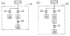
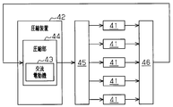
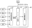
- the schematic block diagram which shows the manufacturing apparatus of the semiconductor device as a vacuum processing apparatus concerning this invention (A) The schematic block diagram which shows the vacuum exhaustion part of the vacuum processing apparatus of FIG. 1, (b) The schematic block diagram which shows the high vacuum exhaustion part of the vacuum processing apparatus of FIG. The systematic diagram of piping which shows the flow of the refrigerant
- FIG. 1 is a schematic configuration diagram illustrating a semiconductor device manufacturing apparatus 10 as a vacuum processing apparatus
- FIG. 2A is a schematic configuration diagram illustrating a configuration of a vacuum exhaust unit
- FIG. 2B is a high vacuum exhaust system. It is a schematic block diagram which shows the structure of a part.
- a semiconductor device manufacturing apparatus 10 is an apparatus for forming a film made of a predetermined metal or the like on a substrate W.
- the manufacturing apparatus 10 includes, for example, a first processing unit 11 including a plurality of chambers for performing a sputtering process, a second processing unit 12 including a plurality of chambers for performing a heat treatment on the substrate W, and the first and And a buffer chamber 13 to which the second processing units 11 and 12 are connected.
- the first processing unit 11 has a transfer chamber 15 having a polygonal cross section.
- Two load lock chambers 16 a and 16 b, four chambers 17, 18, 19 and 20, and one buffer chamber 13 are connected to the transfer chamber 15 through corresponding gate valves 21. Yes.
- Each chamber communicates with the transfer chamber 15 when the corresponding gate valve 21 is opened, and conversely, the chamber is shut off from the transfer chamber 15 when the corresponding gate valve 21 is closed.
- the substrate W is carried into the manufacturing apparatus 10 through the load lock chamber 16a, and the substrate W is carried out to the outside of the manufacturing apparatus 10 through the load lock chamber 16b.
- Each of the four chambers 17, 18, 19, and 20 is a chamber that executes various processes on the substrate W in a vacuum atmosphere.
- the chambers 17 and 20 are made of a metal film made of aluminum using a sputtering method.
- the film is formed on the substrate W, and the chambers 18 and 19 form a metal film made of aluminum on the substrate W using a long throw sputtering method.
- a transfer robot 22 for transferring the substrate W is mounted inside the transfer chamber 15. The transfer robot 22 transfers the substrate W from the transfer chamber 15 to the load lock chambers 16 a and 16 b, the chambers 17, 18, 19 and 20, and the buffer chamber 13 (and in the reverse direction).
- the second processing unit 12 has a transfer chamber 25 having a polygonal cross section, like the first processing unit 11.
- the transfer chamber 25 is connected in a state where the buffer chamber 13 is in communication, and chambers 26, 27, 28, 29, 30, and 31 are connected via corresponding gate valves 21.
- Each chamber communicates with the transfer chamber 15 by opening the corresponding gate valve 21 and, on the contrary, is shut off from the transfer chamber 15 by closing the corresponding gate valve 21.
- a cooling process is performed on the substrate W that has become a high temperature due to various processes.
- Each of the three chambers 27, 30, and 31 is a chamber that executes various processes on the substrate W in a vacuum atmosphere. For example, each of these chambers applies the bias voltage to the substrate W while the substrate W is applied.
- a film forming process is performed in which sputtered particles are deposited on W to form a metal film or a metal nitride film.
- Each of the chambers 28 and 29 is a chamber that performs various processes on the substrate W in a vacuum atmosphere.
- the chamber 28 performs a heat treatment on the substrate W in a reducing gas atmosphere such as hydrogen gas
- the chamber 29 performs a degassing process for removing gas particles attached to the surface of the substrate W.
- a transfer robot 32 for transferring the substrate W is also mounted inside the transfer chamber 25. The transfer robot 32 transfers the substrate W from the transfer chamber 25 to the buffer chamber 13 and the chambers 26, 27, 28, 29, 30, 31 (and in the reverse direction).
- the semiconductor device manufacturing apparatus 10 described above is a so-called cluster-type apparatus in which a plurality of chambers are mounted on the transfer chamber 15 and the transfer chamber 25 that are connected to each other with the buffer chamber 13 interposed therebetween, and each is a vacuum chamber.
- the substrate W is moved between the transfer chamber 15 and the transfer chamber 25 through the buffer chamber 13.
- the substrate W carried into the load lock chamber 16a is sequentially transferred to each chamber, which is a vacuum chamber, by the transfer operation of the transfer robots 22 and 32, and various processes are performed in a vacuum atmosphere in the chamber as the transfer destination. Is done.
- each process such as the sputtering process performed on the substrate W is performed after the chamber is evacuated.
- each chamber is connected to a vacuum evacuation unit 34 that makes the inside of the chamber a vacuum state or a high vacuum evacuation unit 35 that makes the inside of the chamber a high vacuum state having a higher degree of vacuum than the vacuum state. That is, among the chambers constituting the manufacturing apparatus 10, the evacuation unit 34 is connected to a chamber whose degree of vacuum required for the manufacturing apparatus 10 is not high vacuum, and high for a chamber whose degree of vacuum required for it is high.
- a vacuum exhaust unit 35 is connected. For example, as shown in FIG.
- a vacuum exhaust unit 34 is connected to the load lock chambers 16 a and 16 b of the first processing unit 11 and the chambers 26, 28 and 29 of the second processing unit 12.
- a high vacuum exhaust unit 35 is connected to the transfer chamber 15, chambers 17, 18, 19, 20 of the first processing unit 11 and the transfer chamber 25, chambers 27, 30, 31 of the second processing unit 12. .
- the vacuum exhaust unit 34 includes a roughing pump 36 that roughly exhausts the inside of the chamber, and a turbo molecular pump that further exhausts the inside of the roughly exhausted chamber to form a vacuum state. 37, a roughing pump 38 for roughing and exhausting the back pressure side of the turbo molecular pump 37 to ensure the exhaust performance of the turbo molecular pump 37, and a plurality of valves 39 for opening and closing between these components and the chamber. It is composed of When a vacuum state is formed in the chamber, first, the roughing pump 36 and the roughing pump 38 are driven to roughen the inside of the chamber and the back pressure side of the turbo molecular pump 37. Next, the valve 39 between the roughing pump 36 and the chamber is closed, and the valve 39 between the turbo molecular pump 37 and the chamber is opened, whereby the inside of the chamber is evacuated by the turbo molecular pump 37.
- the high vacuum evacuation unit 35 includes a suction side of a turbo molecular pump 37 in addition to the configuration of the vacuum evacuation unit 34 described above in order to bring the connected chamber into a high vacuum state.
- a cryotrap 40 as a decompression device constituting the decompression system is provided.
- the cryotrap 40 includes a cooling unit 41 (see FIG. 3) including a refrigerator and a cooling panel cooled by the refrigerator.
- the cooling unit 41 supplies compressed helium gas (refrigerant) to the refrigerator.
- a compression device 42 see FIG. 3) constituting the decompression system.
- the cryotrap 40 traps a gas such as water vapor remaining in the chamber without being exhausted by the roughing pump 36 and the turbo molecular pump 37 of the high vacuum exhaust unit 35 by condensing it on the cryogenic surface of the cooling panel. It is a device to do.
- the refrigerator of the cooling unit 41 described above is supplied with high-pressure helium gas compressed by the compression device 42, and the cooling panel is cooled to 123K by heat absorption when the high-pressure helium gas is adiabatically expanded. This realizes a cryogenic surface in the cooling panel.
- Each of these cooling panels is provided with a temperature sensor 50 (see FIG. 4) as a temperature detection unit that detects the temperature of the cooling panel.
- the temperature of the cooling part 41 mentioned below shows the temperature of this cooling panel.
- the semiconductor device manufacturing apparatus 10 includes a decompression system corresponding to the high vacuum exhaust unit 35 of the first processing unit 11 and a decompression system corresponding to the high vacuum exhaust unit 35 of the second processing unit 12. . Since these pressure reducing systems have the same basic configuration except that the number of cooling units 41 is different, the pressure reducing system in the first processing unit 11 will be described below, and the pressure reducing system in the second processing unit 12 will be described below. Description is omitted.
- FIG. 3 is a system diagram of piping showing the flow of the refrigerant in the decompression system of the first processing unit 11, and FIG. 4 is an electrical outline relating to the compression device 42 constituting the decompression system of the first processing unit 11. It is a block diagram which shows a structure.
- the compression device 42 constituting the decompression system has a compression section 44 that compresses helium gas as a refrigerant under the driving force of the AC motor 43.
- the helium gas compressed to a high pressure by the compression unit 44 is temporarily stored in the accumulator 45 and then supplied to the refrigerator of each cooling unit 41. That is, the compression device 42 supplies compressed high-pressure helium gas to each cooling unit 41 of the five high vacuum evacuation units 35 in the first processing unit 11.
- the high-pressure helium gas supplied to each cooling unit 41 is adiabatically expanded in the refrigerator of each cooling unit 41 to become a low pressure, temporarily stored in the low-pressure gas storage unit 46, and then again in the compression unit 44 of the compression device 42. Returned.
- the compression device 42 includes a frequency control unit 51, an inverter device 52, and an AC motor 43.
- the temperature sensor 50 provided in each cooling unit 41 of the first processing unit 11 is electrically connected to the frequency control unit 51 and outputs a detection signal indicating the temperature of the cooling unit 41 at that time to the frequency control unit 51.
- the frequency control unit 51 A voltage level corresponding to the target value of the temperature of the cooling unit 41, A voltage level corresponding to the first threshold value of the temperature of the cooling unit 41, Various reference voltages such as a voltage level corresponding to a second threshold value that is a temperature higher than the first threshold value are generated or stored in advance, and voltage levels corresponding to detection results of the respective temperature sensors 50 and these reference voltages Compare
- the target value of the temperature of the cooling unit 41 is the temperature of the cooling unit 41 when the cooling panel can fully and sufficiently exhibit the cooling capacity, and is set to 123K, for example.
- the first threshold value is set to a temperature at which more efficient cooling is required in the cooling panel to be cooled, for example, 128K.
- the second threshold is a temperature at which the temperature of the cooling panel to be cooled is forcibly and rapidly cooled, and is set to 138K, for example.
- the frequency control unit 51 acquires a detection signal from each temperature sensor 50 at a predetermined detection cycle (5 minutes in the present embodiment) immediately after the compressor device 42 is operated, and the inverter device 52 supplies the AC motor 43 with the AC signal.
- the control command value for the frequency of the power supply is output to the inverter device 52.
- the predetermined detection cycle described above is a time sufficient for each cooling unit 41 to be affected by changing the output frequency of the inverter device 52.
- the inverter device 52 converts the frequency of the AC power supplied to the AC motor 43 by once converting the AC power supplied from the external power source 53 (AC 200 V, 50 Hz in this embodiment) into DC and then converting it again into AC. It is a device to change.
- the inverter device 52 can change the frequency of the AC power supply from the external power supply 53 between a lower limit value of 30 Hz and an upper limit value of 50 Hz, and receives this control command value from the frequency control unit 51 to perform this control.
- AC power having a frequency based on the command value is supplied to the AC motor 43.
- the upper limit value of the output frequency of the inverter device 52 is a frequency at which all temperatures of the respective cooling units 41 are forcibly cooled to a target value of 123 K or less.
- the AC motor 43 receives the AC power supplied from the inverter device 52, rotates at a rotational speed corresponding to the frequency of the AC power, and supplies helium gas in an amount corresponding to the rotational speed to each cooling unit 41. More specifically, when the frequency of the AC power supply supplied from the inverter device 52 is increased, the rotational speed of the AC motor 43 is increased, and the supply amount of helium gas supplied to each cooling unit 41 is increased. When the supply amount of helium gas increases in this way, the cooling capacity of all the cooling units 41 connected via the accumulator 45 is improved.
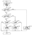
- FIG. 5 is a flowchart showing a flow of control of the output frequency of the inverter device 52 by the frequency control unit 51. This series of processing is executed every predetermined detection cycle described above, that is, every time the frequency control unit 51 acquires the temperature of the cooling unit 41, and is a dedicated logic mounted on the frequency control unit 51.
- the present invention is not limited to this, and for example, it can be embodied by a program or the like installed in a general-purpose computer.
- the frequency control unit 51 acquires the temperature of each cooling unit 41 based on the detection signal from each temperature sensor 50 (step S101). Subsequently, the frequency control unit 51 determines whether or not the temperature of at least one cooling unit 41 among all the cooling units 41 is equal to or higher than a second threshold value of 138 K, that is, a cooling unit that requires forced cooling. It is determined whether or not 41 exists (step S102). When the frequency control unit 51 determines that the temperature is equal to or higher than the second threshold value in at least one cooling unit 41 among all the cooling units 41 (step S102: YES), the output frequency of the inverter device 52 is set to the upper limit value.
- the frequency control unit 51 outputs a control command value instructing to set to a certain 50 Hz to the inverter device 52 (step S103). And the frequency control part 51 performs the forced cooling with respect to all the cooling parts 41 to the AC motor 43, and complete
- the output frequency of the AC power supplied to the AC motor 43 is set to 50 Hz which is the upper limit value thereof.
- the rotation speed is maximized in the AC motor 43, and the supply amount of helium gas supplied to each cooling unit 41 is maximized in the compressor 42.
- the cooling of the cooling unit 41 that is equal to or higher than the second threshold is preferentially executed. As a result, the cooling unit 41 is quickly cooled.
- the frequency control unit 51 determines whether or not the temperature of at least one cooling unit 41 among all the cooling units 41 is equal to or higher than 128 K, which is the first threshold value (step S104). If the frequency control unit 51 determines that the temperature is equal to or higher than the first threshold value in at least one cooling unit 41 among all the cooling units 41 (step S104: YES), the frequency of the current AC power supply is the upper limit value. The frequency control unit 51 determines whether the frequency is 50 Hz, that is, whether the frequency of the AC power supply can be further increased (step S105).
- step S105 If the frequency of the current AC power supply is the upper limit value of 50 Hz (step S105: YES), the frequency control unit 51 determines that it is impossible to increase the frequency of the AC power supply, and determines the frequency of the AC power supply. A control command value for maintaining the upper limit value of 50 Hz is output to the inverter device 52, and the series of processes is terminated. On the other hand, if the current frequency of the AC power supply is not the upper limit of 50 Hz (step S105: NO), a control command value for raising the frequency of the AC power supply by 5 Hz from the current value is output to the inverter device 52. (Step S106), a series of processing ends.
- step S104 when the frequency control unit 51 determines that the temperature in all the cooling units 41 is less than the first threshold value of 128 K (step S104: NO), the current frequency of the AC power supply is the lower limit value of the inverter device 52.
- the frequency control unit 51 determines whether the frequency is 30 Hz, that is, whether the frequency of the AC power supply can be further reduced (step S107). If the frequency of the current AC power supply is 30 Hz, which is the lower limit (step S107: YES), the frequency control unit 51 determines that it is impossible to reduce the frequency of the AC power supply, and determines the frequency of the AC power supply.
- a control command value for maintaining the lower limit of 30 Hz is output to the inverter device 52, and the series of processes is terminated.
- step S107 if the current frequency of the AC power supply is not the lower limit of 30 Hz (step S107: NO), a control command value for reducing the frequency of the AC power supply by 5 Hz from the current value is output to the inverter device 52. (Step S108), a series of processing ends.
- the output frequency of the inverter device 52 is increased by 5 Hz by the frequency control unit 51. . Then, the supply amount of helium gas supplied to all the cooling units 41 is increased by +5 Hz, and the cooling capacity in all the cooling units 41 is increased accordingly.
- the output frequency of the inverter device 52 is lowered by 5 Hz by the frequency control unit 51. Then, the supply amount of helium gas supplied to all the cooling units 41 decreases by 5 Hz, and the cooling capacity in all the cooling units 41 decreases accordingly. Therefore, the power consumption in the compression device 42 can be reduced while efficient cooling corresponding to the temperature at each time is performed in all the cooling units 41.
- FIG. 6 is a timing chart showing the temperature transition of the cooling unit 41 in each chamber of the first processing unit 11 and the output frequency of the inverter device 52 set based on the temperature transition.
- Timings t1 to t10 in FIG. 6 indicate timings for each detection period for detecting the temperature of each cooling unit 41, and the process in each chamber is continued from the idle state (timing t0) in which all the chambers are waiting for processing.
- the timing up to (timing t10) is shown. Note that, in the idle state (timing t0) in which a particularly large exhaust capacity is not required in each chamber, the frequency of the AC power supplied to the AC motor 43 is always set to the lower limit of 30 Hz by the frequency control unit 51. .
- the temperature in all the cooling units 41 is the second threshold (138K), and further the first threshold It is less than (128K). Then, at these timings t0 and t1 at which a particularly large exhaust capacity is not required in each chamber, the AC motor 43 is supplied with AC power of 30 Hz which is a lower limit value. For this reason, at the timing t0 and the timing t1, the output frequency of the inverter device 52 is kept at the lower limit of 30 Hz.
- the frequency control unit 51 determines that the temperature of at least one cooling unit 41 among all the cooling units 41 is equal to or higher than the first threshold value. In addition to this, the frequency control unit 51 determines that the output frequency of the current inverter device 52 is the lower limit value of 30 Hz, thereby increasing the output frequency by 5 Hz from the current frequency (30 Hz). A control command value is input from the frequency control unit 51 to the inverter device 52.
- the frequency control unit 51 determines that the temperature of at least one cooling unit 41 among all the cooling units 41 is equal to or higher than the first threshold value. In addition to this, it is determined in the frequency control unit 51 that the output frequency (35 Hz) in the current inverter device 52 is less than the upper limit value of 50 Hz, thereby only 5 Hz from the current frequency (35 Hz).
- a control command value for increasing the output frequency is input from the frequency control unit 51 to the inverter device 52.
- AC power having a frequency of 40 Hz is supplied to the AC motor 43, the rotational speed of the AC motor 43 is further increased, and the cooling capacity of all the cooling units 41 is further improved.
- the temperature of the cooling unit 41 in the chamber 17 is the first temperature. Although the temperature is less than the threshold, the temperature of the cooling unit 41 in the chamber 20 different from the threshold is equal to or higher than the first threshold. Therefore, at the timing t4, the frequency control unit 51 continues to make a similar determination that the temperature of at least one cooling unit 41 among all the cooling units 41 is equal to or higher than the first threshold in the continuous detection cycle.
- the frequency control unit 51 determines that the output frequency (40 Hz) in the current inverter device 52 is less than the upper limit value of 50 Hz, thereby 5 Hz from the current frequency (40 Hz).
- a control command value for raising the frequency by only the frequency control unit 51 is input to the inverter device 52.
- AC power having a frequency of 45 Hz is supplied to the AC motor 43, the rotational speed of the AC motor 43 is further increased to match the processing content of the chamber 20, and the cooling capacity in each cooling unit 41 is further improved.
- the frequency control unit 51 determines that the temperature of at least one cooling unit 41 among all the cooling units 41 is equal to or higher than the first threshold value.
- the current output frequency of the inverter device 52 (45 Hz) is less than the upper limit value of 50 Hz, whereby the output frequency is 5 Hz from the current frequency (45 Hz).
- a control command value for raising the frequency is input from the frequency control unit 51 to the inverter device 52.
- an AC power supply with a frequency of 50 Hz, which is the upper limit value is supplied to the AC motor 43, thereby maximizing the cooling capacity of each cooling unit 41.
- the AC motor 43 when at least one of the cooling units 41 is continuously equal to or higher than the first threshold, that is, when further cooling is required for any one of the cooling units 41, the AC motor 43 The frequency of the AC power supplied to is increased stepwise. Therefore, the output frequency is further increased in consideration of the temperature change of each cooling unit 41 due to the previous increase in the output frequency. With such a control method, an excessive increase in the output frequency of the inverter device 52 can be avoided, and the electric power consumed by the compression device 42 can be reduced by an amount corresponding to the excessive increase in the frequency. .
- the frequency control unit 51 determines that there is no cooling unit 41 having a temperature equal to or higher than the first threshold value. In addition, the frequency control unit 51 determines that the current output frequency (50 Hz) in the inverter device 52 is higher than the lower limit (30 Hz). As a result, a control command value for reducing the output frequency by 5 Hz from the current frequency is input from the frequency control unit 51 to the inverter device 52. As a result, the rotational speed of the AC motor 43 becomes low, and it becomes difficult for all the cooling units 41 to generate excessive cooling capacity.
- the current value is A control command value for reducing the output frequency by 5 Hz from the frequency is input from the frequency control unit 51 to the inverter device 52.
- the frequency of the AC power output from the inverter device 52 reaches the lower limit (30 Hz) at timing t9, the frequency of the AC power supplied to the AC motor 43 is maintained at the lower limit of 30 Hz after timing t10. Is done.
- the output frequency is further reduced in consideration of the temperature change of each cooling unit 41 due to the decrease in the previous output frequency.
- the output frequency of the inverter device 52 can be reduced according to the temperature of the cooling unit 41 at that time, and the power consumed by the compressor 42 is reduced by the amount of the reduced output frequency. be able to.
- the power consumption in the said manufacturing apparatus 10 can be reduced by the part of the power consumption reduced with the pressure reduction system.
- the frequency of the AC power supplied to the AC motor 43 is an upper limit value. It continues to be maintained at a certain 50 Hz. Further, for example, when it is temporarily determined that at least one temperature of each cooling unit 41 is equal to or higher than the first threshold at timing t8, the inverter device 52 is increased by 5 Hz from the current frequency (40 Hz). A control command value is input from the frequency control unit 51 to the inverter device 52.
- a control command value for forcibly setting the output frequency to the upper limit value of 50 Hz is input to the inverter device 52.
- the following effects can be obtained.
- (1) Among all the cooling units 41 when the temperature of at least one cooling unit 41 is equal to or higher than the first threshold, the output frequency of the inverter device 52 is increased by the frequency control unit 51, and all the cooling units 41 When the temperature of the inverter device 52 is lower than the first threshold, the output frequency of the inverter device 52 is also lowered by the frequency control unit 51.
- the output frequency control method when further cooling is required for the cooling unit 41, the supply amount of helium gas supplied to each cooling unit 41 increases, and the cooling capacity in each cooling unit 41 is enhanced. Will be.
- the frequency control unit 51 acquires the temperature of each cooling unit 41 at every predetermined detection cycle, and the temperature of at least one cooling unit 41 among all the cooling units 41 is equal to or higher than the first threshold value
- the output frequency to the inverter device 52 is increased stepwise for each detection period toward the upper limit value. That is, the output frequency is further increased in consideration of the temperature change of each cooling unit 41 caused by increasing the previous output frequency.
- the frequency control unit 51 acquires the temperature of each cooling unit 41 for each predetermined detection cycle, and when the temperatures of all the cooling units 41 are less than the first threshold, the output frequency of the inverter device 52 is set. The value is decreased stepwise for each predetermined detection period toward the lower limit value. Therefore, the output frequency is further reduced in consideration of the temperature change of each cooling unit 41 due to the decrease in the previous output frequency. As a result, the output frequency of the inverter device 52 can be reduced according to the temperature of the cooling unit 41 at that time, and the power consumed by the compressor 42 can be reduced by the amount of the reduced output frequency. it can.
- the frequency control unit 51 sets the output frequency of the inverter device 52 to the upper limit value of 50 Hz when the temperature of at least one cooling unit 41 of all the cooling units 41 is equal to or higher than the second threshold value.
- the said embodiment can also be changed and implemented as follows.
- the decompression system is applied to the semiconductor device manufacturing apparatus 10 as a vacuum processing apparatus. You may apply to.
- the frequency control part 51 of the said embodiment outputs the output frequency of the inverter apparatus 52 when the temperature of at least 1 cooling part 41 is more than a 2nd threshold value among all the cooling parts 41. Set to the highest possible value. However, the control based on the second threshold value may be omitted. In the above embodiment, when the temperature of at least one cooling unit 41 among all the cooling units 41 is equal to or higher than the first threshold value, the cooling unit 41 is further cooled. Therefore, even if the control based on the second threshold is omitted, the present invention can obtain at least the effects (1) to (3).
- the frequency control part 51 of the said embodiment sets the output frequency of the inverter apparatus 52 for every said detection period, when the temperature of all the cooling parts 41 falls below a 1st threshold value based on the temperature of each cooling part 41.
- the output frequency was controlled to gradually decrease toward the lower limit.
- the frequency control unit 51 may set the output frequency of the inverter device 52 to the lower limit value when the temperature of all the cooling units 41 falls below the first threshold value. Even if it is such a structure, this invention can acquire the effect of said (1) and (2) at least.
- the frequency control part 51 of the said embodiment is an inverter apparatus, when the temperature of the at least 1 cooling part 41 is more than a 1st threshold value among all the cooling parts 41 based on the temperature of each cooling part 41.
- the output frequency was controlled so as to increase the output frequency of 52 stepwise toward the upper limit value for each detection period.
- the frequency control unit 51 controls the output frequency of the inverter device 52 with two values, a lower limit value and an upper limit value. May be.
- the frequency control unit 51 may enhance the cooling effect by setting the output frequency of the inverter device 52 to the upper limit value when the temperature of at least one cooling unit 41 is equal to or higher than the first threshold value.
- the frequency control part 51 of the said embodiment acquired the temperature of each cooling part 41 for every predetermined
- the frequency control unit 51 may continuously acquire the temperature of the cooling unit 41 and control the output frequency of the inverter device 52.
- the frequency control unit 51 of the above embodiment does not increase the output frequency of the inverter device 52 stepwise when at least one temperature of the cooling unit 41 is equal to or higher than the first threshold, but the temperature of the cooling unit 41
- the output frequency of the inverter device 52 may be set so as to be a frequency according to the above.
- the frequency control unit 51 uses an inverter so as to have a frequency corresponding to the highest temperature among the cooling units 41.
- the output frequency of the device 52 may be set.
- the number of the cooling parts 41 which are the supply object of the compression apparatus 42 is two or more numbers according to the feeding capability of the compression apparatus 42, it will not specifically limit to the number. .
- the cryotrap 40 is used as the decompression device, but a cryopump may be used as the decompression device.
- a cryopump when used as the decompression device, it is preferable to appropriately change the first threshold value and the second threshold value.
- step S105 (comparison with the upper limit of 50 Hz) and step S107 (comparison with the lower limit of 30 Hz) may be omitted. That is, when the temperature of at least one cooling unit 41 is equal to or higher than the first threshold (128K), the output frequency is immediately increased relatively (for example, 5 Hz), and the temperatures of all the cooling units 41 are increased to the first threshold (128K). ), The output frequency may be immediately decreased relatively (for example, 5 Hz).
Landscapes
- Engineering & Computer Science (AREA)
- Mechanical Engineering (AREA)
- General Engineering & Computer Science (AREA)
- Physics & Mathematics (AREA)
- Thermal Sciences (AREA)
- Compressors, Vaccum Pumps And Other Relevant Systems (AREA)
- Inverter Devices (AREA)
- Control Of Positive-Displacement Pumps (AREA)
Abstract
Description
・冷却部41の温度の目標値に相当する電圧レベル、
・冷却部41の温度の第1の閾値に相当する電圧レベル、
・第1の閾値よりも高い温度である第2の閾値に相当する電圧レベル
といった各種の参照電圧を生成または予め記憶し、各温度センサ50の検出結果に相当する電圧レベルとこれらの参照電圧とを比較する。
(1)全ての冷却部41のうち、少なくとも1つ冷却部41の温度が第1の閾値以上のときに、インバータ装置52の出力周波数が周波数制御部51によって上げられ、各冷却部41の全ての温度が第1の閾値未満であるときに、インバータ装置52の出力周波数が同じく周波数制御部51によって下げられる。こうした出力周波数の制御方法であれば、冷却部41に対してさらなる冷却が必要であるときには、各冷却部41に供給されるヘリウムガスの供給量が増加し、各冷却部41における冷却能力が増強されることとなる。一方、冷却部41に対してさらなる冷却が必要でないときには、各冷却部41に供給されるヘリウムガスの供給量が減少し、各冷却部41の冷却能力が減衰することとなる。それゆえ、各冷却部41をその時々の温度に応じて効率よく冷却しつつ、出力周波数を下げる期間にあっては、圧縮装置42で消費される電力を削減させることが可能となる。
・上記実施形態では、減圧システムを真空処理装置としての半導体装置の製造装置10に適用したが、これに限らず、減圧装置と圧縮装置とを利用する装置であれば、本発明は他の装置に適用してもよい。
Claims (7)
- 減圧システムであって、
圧縮された冷媒を受け取り、該圧縮された冷媒を断熱膨張させるときに気体を補足可能な冷却部を各々含む複数の減圧装置と、
交流電動機を有する圧縮部を含み、前記交流電動機の回転速度に応じた流量で前記圧縮部から前記複数の減圧装置の各々の冷却部に前記圧縮された冷媒を供給する圧縮装置と、
前記各減圧装置の冷却部の温度を検出する温度検出部と、
前記交流電動機に供給する交流電源の周波数を変更可能なインバータ装置と、
前記インバータ装置の出力周波数を制御する周波数制御部とを備え、
前記周波数制御部は、
前記複数の減圧装置のうち少なくとも1つの減圧装置の冷却部の温度が第1の閾値以上のときに前記インバータ装置の出力周波数を相対的に上げ、前記複数の減圧装置すべての冷却部の温度が前記第1の閾値未満に下がったときに前記インバータ装置の出力周波数を相対的に下げることを特徴とする減圧システム。 - 前記周波数制御部は、
所定の検出周期毎に各減圧装置の冷却部の温度を取得し、
前記少なくとも1つの減圧装置の冷却部の温度が前記第1の閾値以上か否かを前記検出周期毎に判定して前記インバータ装置の出力周波数を上げることを特徴とする請求項1に記載の減圧システム。 - 前記周波数制御部は更に、
前記少なくとも1つの減圧装置の冷却部の温度が前記第1の閾値以上であるとき、前記前記インバータ装置の出力周波数が上限値まで上昇しているかを判定し、そうでなければ前記出力周波数を上げることを特徴とする請求項2に記載の減圧システム。 - 前記周波数制御部は、
所定の検出周期毎に各減圧装置の冷却部の温度を取得し、
前記複数の減圧装置すべての冷却部の温度が前記第1の閾値未満か否かを前記検出周期毎に判定して前記インバータ装置の出力周波数を下げることを特徴とする請求項1乃至3の何れか一項に記載の減圧システム。 - 前記周波数制御部は更に、
前記少なくとも1つの減圧装置の冷却部の温度が前記第1の閾値未満であるとき、前記前記インバータ装置の出力周波数が下限値まで低下しているかを判定し、そうでなければ前記出力周波数を下げることを特徴とする請求項4に記載の減圧システム。 - 前記周波数制御部は、
前記少なくとも1つの減圧装置の冷却部の温度が前記第1の閾値よりも高い第2の閾値以上である場合には、前記インバータ装置の出力周波数を上限値に設定することを特徴とする請求項1,2,4の何れか一項に記載の減圧システム。 - 減圧システムであって、
複数の真空チャンバと、
請求項1~6のいずれか一項に記載の減圧システムとを備え、前記複数の真空チャンバの各々が前記複数の減圧装置の一つに接続されていることを特徴とする真空処理装置。
Priority Applications (6)
| Application Number | Priority Date | Filing Date | Title |
|---|---|---|---|
| JP2011522769A JP5466235B2 (ja) | 2009-07-15 | 2010-06-24 | 減圧システム及び真空処理装置 |
| DE112010002922T DE112010002922T5 (de) | 2009-07-15 | 2010-06-24 | Druckabbau-System und Vakuum-Behandlungsvorrichtung |
| KR1020117027280A KR101234698B1 (ko) | 2009-07-15 | 2010-06-24 | 감압 시스템 및 진공 처리 장치 |
| SG2011083375A SG176036A1 (en) | 2009-07-15 | 2010-06-24 | Pressure reduction system and vacuum treatment device |
| CN201080022279.3A CN102428275B (zh) | 2009-07-15 | 2010-06-24 | 减压系统及真空处理装置 |
| US13/320,888 US20120060533A1 (en) | 2009-07-15 | 2010-06-24 | Pressure reduction system and vacuum treatment device |
Applications Claiming Priority (2)
| Application Number | Priority Date | Filing Date | Title |
|---|---|---|---|
| JP2009-166701 | 2009-07-15 | ||
| JP2009166701 | 2009-07-15 |
Publications (1)
| Publication Number | Publication Date |
|---|---|
| WO2011007652A1 true WO2011007652A1 (ja) | 2011-01-20 |
Family
ID=43449262
Family Applications (1)
| Application Number | Title | Priority Date | Filing Date |
|---|---|---|---|
| PCT/JP2010/060739 Ceased WO2011007652A1 (ja) | 2009-07-15 | 2010-06-24 | 減圧システム及び真空処理装置 |
Country Status (8)
| Country | Link |
|---|---|
| US (1) | US20120060533A1 (ja) |
| JP (1) | JP5466235B2 (ja) |
| KR (1) | KR101234698B1 (ja) |
| CN (1) | CN102428275B (ja) |
| DE (1) | DE112010002922T5 (ja) |
| SG (1) | SG176036A1 (ja) |
| TW (1) | TWI463072B (ja) |
| WO (1) | WO2011007652A1 (ja) |
Cited By (1)
| Publication number | Priority date | Publication date | Assignee | Title |
|---|---|---|---|---|
| JP2014025625A (ja) * | 2012-07-26 | 2014-02-06 | Ulvac Japan Ltd | 減圧システム |
Families Citing this family (3)
| Publication number | Priority date | Publication date | Assignee | Title |
|---|---|---|---|---|
| WO2014132301A1 (ja) * | 2013-02-28 | 2014-09-04 | キヤノンアネルバ株式会社 | 真空処理装置 |
| JP6410589B2 (ja) * | 2014-12-17 | 2018-10-24 | 住友重機械工業株式会社 | クライオポンプ、クライオポンプの制御方法、及び冷凍機 |
| CN109877839B (zh) * | 2019-03-25 | 2021-07-02 | 济南翼菲自动化科技有限公司 | 一种机器人取放柔性路径算法 |
Citations (4)
| Publication number | Priority date | Publication date | Assignee | Title |
|---|---|---|---|---|
| JP3090110U (ja) * | 2002-05-20 | 2002-11-29 | 長州産業株式会社 | 真空装置用省エネユニット |
| JP2003113779A (ja) * | 2001-07-20 | 2003-04-18 | Helix Technol Corp | ヘリウム管理制御システム |
| JP2005048764A (ja) * | 2003-07-29 | 2005-02-24 | Sumitomo Heavy Ind Ltd | 真空ポンプ制御システム |
| JP2008014599A (ja) * | 2006-07-07 | 2008-01-24 | Sumitomo Heavy Ind Ltd | 圧縮機用電源 |
Family Cites Families (14)
| Publication number | Priority date | Publication date | Assignee | Title |
|---|---|---|---|---|
| JPH0390110A (ja) * | 1989-09-01 | 1991-04-16 | Sanyo Electric Co Ltd | 自動炊飯装置 |
| US5386708A (en) * | 1993-09-02 | 1995-02-07 | Ebara Technologies Incorporated | Cryogenic vacuum pump with expander speed control |
| EP0918159B1 (en) * | 1994-04-28 | 2002-11-20 | Ebara Corporation | Cryopump |
| US5775109A (en) * | 1997-01-02 | 1998-07-07 | Helix Technology Corporation | Enhanced cooldown of multiple cryogenic refrigerators supplied by a common compressor |
| US6096267A (en) * | 1997-02-28 | 2000-08-01 | Extraction Systems, Inc. | System for detecting base contaminants in air |
| US5918473A (en) * | 1997-05-09 | 1999-07-06 | Alcan International Limited | Method and apparatus for measuring quenchant properties of coolants |
| JP2002070737A (ja) | 2000-08-31 | 2002-03-08 | Ulvac Kuraio Kk | クライオポンプの再生方法 |
| US6691524B2 (en) * | 2002-03-29 | 2004-02-17 | General Electric Company | Methods and apparatus for controlling compressor speed |
| JP2004060644A (ja) * | 2002-06-05 | 2004-02-26 | Denso Corp | 圧縮機装置およびその制御方法 |
| US7555911B2 (en) * | 2002-08-20 | 2009-07-07 | Sumitomo Heavy Industries, Ltd. | Cryogenic refrigerator |
| US7895854B2 (en) * | 2005-06-01 | 2011-03-01 | Hewlett-Packard Development Company, L.P. | Refrigeration system with parallel evaporators and variable speed compressor |
| US20070125104A1 (en) * | 2005-12-06 | 2007-06-07 | Ranco Incorporated Of Delaware | Compressor system for vending devices and the like |
| JP2009001950A (ja) | 2007-06-25 | 2009-01-08 | Kaneka Corp | 合成皮革 |
| US20090133418A1 (en) * | 2007-11-26 | 2009-05-28 | Ya De Li Technology.Inc. | Plug-in circuit and cooling system thereof |
-
2010
- 2010-06-24 KR KR1020117027280A patent/KR101234698B1/ko active Active
- 2010-06-24 SG SG2011083375A patent/SG176036A1/en unknown
- 2010-06-24 WO PCT/JP2010/060739 patent/WO2011007652A1/ja not_active Ceased
- 2010-06-24 JP JP2011522769A patent/JP5466235B2/ja active Active
- 2010-06-24 US US13/320,888 patent/US20120060533A1/en not_active Abandoned
- 2010-06-24 CN CN201080022279.3A patent/CN102428275B/zh active Active
- 2010-06-24 DE DE112010002922T patent/DE112010002922T5/de not_active Ceased
- 2010-07-01 TW TW099121748A patent/TWI463072B/zh active
Patent Citations (4)
| Publication number | Priority date | Publication date | Assignee | Title |
|---|---|---|---|---|
| JP2003113779A (ja) * | 2001-07-20 | 2003-04-18 | Helix Technol Corp | ヘリウム管理制御システム |
| JP3090110U (ja) * | 2002-05-20 | 2002-11-29 | 長州産業株式会社 | 真空装置用省エネユニット |
| JP2005048764A (ja) * | 2003-07-29 | 2005-02-24 | Sumitomo Heavy Ind Ltd | 真空ポンプ制御システム |
| JP2008014599A (ja) * | 2006-07-07 | 2008-01-24 | Sumitomo Heavy Ind Ltd | 圧縮機用電源 |
Cited By (1)
| Publication number | Priority date | Publication date | Assignee | Title |
|---|---|---|---|---|
| JP2014025625A (ja) * | 2012-07-26 | 2014-02-06 | Ulvac Japan Ltd | 減圧システム |
Also Published As
| Publication number | Publication date |
|---|---|
| TWI463072B (zh) | 2014-12-01 |
| TW201107603A (en) | 2011-03-01 |
| JP5466235B2 (ja) | 2014-04-09 |
| KR20120018164A (ko) | 2012-02-29 |
| JPWO2011007652A1 (ja) | 2012-12-27 |
| US20120060533A1 (en) | 2012-03-15 |
| KR101234698B1 (ko) | 2013-02-19 |
| CN102428275B (zh) | 2015-03-11 |
| DE112010002922T5 (de) | 2012-09-20 |
| CN102428275A (zh) | 2012-04-25 |
| SG176036A1 (en) | 2011-12-29 |
Similar Documents
| Publication | Publication Date | Title |
|---|---|---|
| US10982662B2 (en) | Pumping system | |
| KR101570657B1 (ko) | 공유 진공 펌프를 구비한 트윈 챔버 프로세싱 시스템 | |
| CN102165192B (zh) | 真空排气系统、冷冻机、低温泵及其运转方法、以及基板处理装置 | |
| US20110162959A1 (en) | Vacuum pumping system, substrate processing apparatus, manufacturing method of electronic device, and operating method of vacuum pumping system | |
| US20060222506A1 (en) | Rapidly pumping out an enclosure while limiting energy consumption | |
| US20030068233A1 (en) | Device and method for reducing vacuum pump energy consumption | |
| JP5377666B2 (ja) | 真空排気装置及び真空排気方法及び基板処理装置 | |
| KR20100046274A (ko) | 배기 시스템 | |
| JP5466235B2 (ja) | 減圧システム及び真空処理装置 | |
| EP1077329A1 (en) | Vacuum device | |
| TWI489042B (zh) | Cryogenic pump and vacuum exhaust method | |
| JP4180265B2 (ja) | 真空排気装置の運転方法 | |
| JP4927642B2 (ja) | 二段式冷凍機の運転制御方法、二段式冷凍機を用いたクライオポンプの運転制御方法、二段式冷凍機及びクライオポンプ | |
| WO2010097888A1 (ja) | 二段式冷凍機の運転制御方法、二段式冷凍機を有するクライオポンプの運転制御方法、二段式冷凍機、クライオポンプ及び真空基板処理装置 | |
| JP5956754B2 (ja) | 真空排気システム | |
| JP2005232977A (ja) | 真空装置 | |
| JP3107794U (ja) | 真空排気装置 | |
| JP5978045B2 (ja) | 減圧システム | |
| WO2011052675A1 (ja) | ポンプユニット,ロードロックチャンバの排気装置,及び真空装置 | |
| JP2001317457A (ja) | クライオポンプの運転方法 | |
| JPH06306601A (ja) | スパッタリング装置の排気機構 | |
| JP2012031493A (ja) | インライン成膜装置 |
Legal Events
| Date | Code | Title | Description |
|---|---|---|---|
| WWE | Wipo information: entry into national phase |
Ref document number: 201080022279.3 Country of ref document: CN |
|
| 121 | Ep: the epo has been informed by wipo that ep was designated in this application |
Ref document number: 10799712 Country of ref document: EP Kind code of ref document: A1 |
|
| ENP | Entry into the national phase |
Ref document number: 2011522769 Country of ref document: JP Kind code of ref document: A |
|
| ENP | Entry into the national phase |
Ref document number: 20117027280 Country of ref document: KR Kind code of ref document: A |
|
| WWE | Wipo information: entry into national phase |
Ref document number: 13320888 Country of ref document: US |
|
| WWE | Wipo information: entry into national phase |
Ref document number: 112010002922 Country of ref document: DE Ref document number: 1120100029229 Country of ref document: DE |
|
| 122 | Ep: pct application non-entry in european phase |
Ref document number: 10799712 Country of ref document: EP Kind code of ref document: A1 |