WO2011004812A1 - ガバナ制御装置および制御方法 - Google Patents
ガバナ制御装置および制御方法 Download PDFInfo
- Publication number
- WO2011004812A1 WO2011004812A1 PCT/JP2010/061460 JP2010061460W WO2011004812A1 WO 2011004812 A1 WO2011004812 A1 WO 2011004812A1 JP 2010061460 W JP2010061460 W JP 2010061460W WO 2011004812 A1 WO2011004812 A1 WO 2011004812A1
- Authority
- WO
- WIPO (PCT)
- Prior art keywords
- governor
- command
- engine
- output
- control device
- Prior art date
- Legal status (The legal status is an assumption and is not a legal conclusion. Google has not performed a legal analysis and makes no representation as to the accuracy of the status listed.)
- Ceased
Links
Images

Classifications
-
- F—MECHANICAL ENGINEERING; LIGHTING; HEATING; WEAPONS; BLASTING
- F02—COMBUSTION ENGINES; HOT-GAS OR COMBUSTION-PRODUCT ENGINE PLANTS
- F02D—CONTROLLING COMBUSTION ENGINES
- F02D23/00—Controlling engines characterised by their being supercharged
-
- F—MECHANICAL ENGINEERING; LIGHTING; HEATING; WEAPONS; BLASTING
- F02—COMBUSTION ENGINES; HOT-GAS OR COMBUSTION-PRODUCT ENGINE PLANTS
- F02D—CONTROLLING COMBUSTION ENGINES
- F02D29/00—Controlling engines, such controlling being peculiar to the devices driven thereby, the devices being other than parts or accessories essential to engine operation, e.g. controlling of engines by signals external thereto
- F02D29/02—Controlling engines, such controlling being peculiar to the devices driven thereby, the devices being other than parts or accessories essential to engine operation, e.g. controlling of engines by signals external thereto peculiar to engines driving vehicles; peculiar to engines driving variable pitch propellers
-
- F—MECHANICAL ENGINEERING; LIGHTING; HEATING; WEAPONS; BLASTING
- F02—COMBUSTION ENGINES; HOT-GAS OR COMBUSTION-PRODUCT ENGINE PLANTS
- F02D—CONTROLLING COMBUSTION ENGINES
- F02D31/00—Use of speed-sensing governors to control combustion engines, not otherwise provided for
- F02D31/001—Electric control of rotation speed
- F02D31/002—Electric control of rotation speed controlling air supply
-
- F—MECHANICAL ENGINEERING; LIGHTING; HEATING; WEAPONS; BLASTING
- F02—COMBUSTION ENGINES; HOT-GAS OR COMBUSTION-PRODUCT ENGINE PLANTS
- F02D—CONTROLLING COMBUSTION ENGINES
- F02D41/00—Electrical control of supply of combustible mixture or its constituents
- F02D41/0002—Controlling intake air
- F02D41/0007—Controlling intake air for control of turbo-charged or super-charged engines
-
- F—MECHANICAL ENGINEERING; LIGHTING; HEATING; WEAPONS; BLASTING
- F02—COMBUSTION ENGINES; HOT-GAS OR COMBUSTION-PRODUCT ENGINE PLANTS
- F02D—CONTROLLING COMBUSTION ENGINES
- F02D41/00—Electrical control of supply of combustible mixture or its constituents
- F02D41/02—Circuit arrangements for generating control signals
- F02D41/04—Introducing corrections for particular operating conditions
- F02D41/042—Introducing corrections for particular operating conditions for stopping the engine
-
- F—MECHANICAL ENGINEERING; LIGHTING; HEATING; WEAPONS; BLASTING
- F02—COMBUSTION ENGINES; HOT-GAS OR COMBUSTION-PRODUCT ENGINE PLANTS
- F02B—INTERNAL-COMBUSTION PISTON ENGINES; COMBUSTION ENGINES IN GENERAL
- F02B37/00—Engines characterised by provision of pumps driven at least for part of the time by exhaust
-
- Y—GENERAL TAGGING OF NEW TECHNOLOGICAL DEVELOPMENTS; GENERAL TAGGING OF CROSS-SECTIONAL TECHNOLOGIES SPANNING OVER SEVERAL SECTIONS OF THE IPC; TECHNICAL SUBJECTS COVERED BY FORMER USPC CROSS-REFERENCE ART COLLECTIONS [XRACs] AND DIGESTS
- Y02—TECHNOLOGIES OR APPLICATIONS FOR MITIGATION OR ADAPTATION AGAINST CLIMATE CHANGE
- Y02T—CLIMATE CHANGE MITIGATION TECHNOLOGIES RELATED TO TRANSPORTATION
- Y02T10/00—Road transport of goods or passengers
- Y02T10/10—Internal combustion engine [ICE] based vehicles
- Y02T10/12—Improving ICE efficiencies
Definitions
- the present invention relates to an engine governor control device equipped with a turbocharger.
- Patent Document 1 since the fuel input amount is kept constant with respect to the load fluctuation, it cannot be said that the adequate governor control is necessarily performed, and the fuel consumption can be improved sufficiently. Absent. Moreover, although patent document 1 respond
- An object of the present invention is to improve fuel efficiency by performing more precise governor control in consideration of turbo lag in an engine equipped with a turbocharger.
- a governor control device is a governor control device for an engine having a turbocharger, and calculates and outputs a governor command based on a deviation between a rotational speed command and an actual engine rotational speed, and an engine And a regulation means for stopping the output of the governor command based on the above calculation over a predetermined period when the actual rotational speed is smaller than the rotational speed command, and gradually increasing and outputting the governor command during that period.
- the governor control method of the present invention is a governor control method for an engine equipped with a turbocharger, which calculates and outputs a governor command based on a deviation between the rotational speed command and the actual engine rotational speed, When the number is smaller than the rotational speed command, the governor command based on the above calculation is stopped for a predetermined period, and the governor command is gradually increased and output during that period.
- the predetermined period corresponds to a turbo lag period.
- the governor command is substantially continuously increased and output.
- the increase amount of the governor command is, for example, 1% to 10% of the current governor command. %.
- the governor control device and control method of the present invention are particularly suitable for controlling a main engine for a ship.
- the ship of the present invention includes a hull, an engine mounted on the hull, a turbocharger that supercharges the engine, and a governor control device that controls the amount of fuel input to the engine.
- the control means for calculating and outputting the governor command based on the deviation between the rotational speed command and the actual engine speed, and when the actual engine rotational speed is smaller than the rotational speed command, the device performs the calculation over a predetermined period.
- FIG. 1 is a block diagram showing a configuration of a marine engine governor control system according to an embodiment of the present invention.
- the governor control system 10 of the present embodiment is provided with a turbocharger 13T and controls the amount of fuel input to the main machine 13 connected to the propeller 12 via the main shaft 11.
- the governor control system 10 receives the rotational speed command, monitors the rotation of a turning gear (not shown) provided on the main shaft 11, detects the actual rotational speed of the engine at the actual rotational speed detection block 14, and moves to the input side. Feedback. That is, the deviation between the rotational speed command and the actual engine rotational speed is input to the PID calculation unit 15.
- the deviation input to the PID calculation unit 15 is subjected to a proportional operation P, an integration operation I, and a differentiation operation D, and the output is input to the switch 16.
- the switch 16 receives an output from the PID control restriction unit 17. That is, the switch 16 selectively switches the output from the PID calculation unit 15 and the output from the PID control regulation unit 17 and supplies the fuel supply device 18 that supplies fuel to the main engine 13 as a governor command.
- the governor command corresponds to, for example, a lever position (governor position) for controlling the plunger capacity.
- the PID control restriction unit 17 receives the current governor command, which is an output from the switch 16, as an input, and adds, for example, 1% of the input to the output.
- the switch 16 is switched by a comparison unit 19 that compares the actual engine speed (input A) and the engine speed command (input B) from the actual engine speed detection block 14. That is, the comparison unit 19 outputs, for example, a Hi signal when the actual rotational speed is smaller than the rotational speed command, the switch 16 selects the output from the PID control restricting unit 17, and otherwise (the actual engine rotational speed is For example, the comparison unit 19 outputs a Lo signal, and the switch 16 selects the output from the PID calculation unit 15.
- the output of the comparison unit 19 is also used as a reset signal for resetting the integral value in the I operation of the PID calculation unit 15.
- the resetting of the I operation is performed when the governor command is switched from the output from the PID control restricting unit 17 to the output from the PID calculating unit 15, and in the example of the above Hi and Lo signals, it is switched from Hi to Lo.
- the integrated value is reset to the current governor command value.
- the output from the PID control restriction unit 17 is used as the governor command
- the actual engine rotational speed is equal to or higher than the rotational speed command
- the output from the PID calculation unit 15 is used as a governor command.
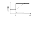
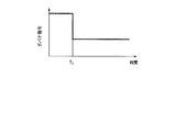
- FIGS. 2 and 3 show time series changes of the governor command in the governor control system 10 respectively.
- the horizontal axis represents time
- the vertical axis represents the governor command value.
- a continuous line shows the value of the governor command which is an output of the PID calculating part 15, and a broken line shows the output of the switch 16.
- FIG. 2 corresponds to the case where the actual rotational speed becomes smaller than the rotational speed command, that is, when the load increases and the rotational speed decreases, or when the rotational speed command is increased (for example, when the ship is accelerated).
- the governor command from the switch 16 to the fuel supply device 18 is changed from the output of the PID calculation unit 15 to the PID control regulation.
- the output is switched to the output of the unit 17.
- the governor command gradually increases over a period T (inclination of 1%) as indicated by a broken line.
- the period T elapses, the actual engine speed reaches the speed command, and the output of the switch 16 Resets the I operation to the current governor command value and switches the selection to the output from the PID calculation unit 15.
- FIG. 3 shows a case where the actual engine speed becomes equal to or higher than the engine speed command, that is, when the load decreases and the engine speed increases, or when the engine speed command is lowered (for example, when the ship is decelerated).
- the governor command from the switch 16 to the fuel supply device 18 is maintained at the output of the PID calculation unit 15. .
- the governor command changes as indicated by the broken line in the same manner as the solid line during normal PID control.
- the period T is set to a predetermined period corresponding to the turbo lag of the turbocharger 13T, and the increase rate is set in accordance with this. That is, in the present embodiment, the current governor command is gradually increased by 1%, but the output of the PID control restriction unit 17 is switched to the output from the PID control restriction unit 17 in a period substantially corresponding to a turbo lag.
- the rate of increase is, for example, about 1% to 10%. Further, the increasing method is not limited to the configuration of the present embodiment.
- the present embodiment even when a turbo lag is present, it is possible to suppress a rapid increase in the amount of fuel input during an increase in load such as during stormy weather or during acceleration, and to prevent a decrease in the excess air ratio. This can improve fuel efficiency. In addition, when the load is reduced or decelerated, the amount of fuel input can be reduced more quickly to prevent engine overspeed. Further, in the present embodiment, since the governor command is gradually increased even when the PID control is restricted, it is possible to increase the amount of fuel input corresponding to the increase in scavenging air pressure, and to realize more appropriate governor control.
- the present invention is particularly effective for a large marine diesel engine, but can also be applied to, for example, a large land engine.
- control method is not limited to PID control, but can be applied to modern control theory, application control, learning control, and the like.
Landscapes
- Engineering & Computer Science (AREA)
- Chemical & Material Sciences (AREA)
- Combustion & Propulsion (AREA)
- Mechanical Engineering (AREA)
- General Engineering & Computer Science (AREA)
- Output Control And Ontrol Of Special Type Engine (AREA)
- Electrical Control Of Air Or Fuel Supplied To Internal-Combustion Engine (AREA)
- Combined Controls Of Internal Combustion Engines (AREA)
- Control Of Vehicle Engines Or Engines For Specific Uses (AREA)
Abstract
回転数指令とエンジン実回転数の間の偏差に基づきガバナ指令を演算して出力する制御手段と、エンジン実回転数が回転数指令よりも小さいときに、所定期間に渡って上記演算に基づくガバナ指令の出力を停止し、その間ガバナ指令を漸次増大して出力する規制手段とを備えるターボ過給機を備えるエンジンのガバナ制御装置。
Description
本発明は、ターボ過給機を備えたエンジンのガバナ制御装置に関する。
例えば舶用エンジンの制御では、設定された目標回転数と実回転数の差がなくなるようにガバナ制御が行われる。しかし、ターボ過給機を備えた舶用エンジンにおいて、荒天時の波浪による短い周期の負荷変動に追従して燃料投入量を増減させると、負荷増大時に空気過剰率が低下して燃費の悪化を招く。このような問題に対して、波浪による負荷の増大時に、燃料投入量を一定に保持する構成が提案されている(特許文献1)。
特開平4-31645号公報
しかし、特許文献1の構成では、負荷変動に対して燃料投入量を一定に保持しているため、必ずしも十分適正なガバナ制御が行われているとは言えず、燃費の改善も十分とは言えない。また、特許文献1は、波浪による負荷変動における空気過剰率の低下には対応しているが、船舶の加速を目的として目標回転数が上げられる場合に発生する空気過剰率低下の問題に対応することはできない。
本発明は、ターボ過給機を備えたエンジンにおいて、ターボラグを考慮してより精密なガバナ制御を行い燃費の改善を図ることを課題としている。
本発明のガバナ制御装置は、ターボ過給機を備えるエンジンのガバナ制御装置であって、回転数指令とエンジン実回転数の間の偏差に基づきガバナ指令を演算して出力する制御手段と、エンジン実回転数が回転数指令よりも小さいときに、所定期間に渡って上記演算に基づくガバナ指令の出力を停止し、その間ガバナ指令を漸次増大して出力する規制手段とを備えたことを特徴としている。
また本発明のガバナ制御方法は、ターボ過給機を備えるエンジンのガバナ制御方法であって、回転数指令とエンジン実回転数の間の偏差に基づきガバナ指令を演算して出力し、エンジン実回転数が回転数指令よりも小さいときに、所定期間に渡って上記演算に基づくガバナ指令を停止し、その間ガバナ指令を漸次増大して出力することを特徴としている。
所定期間はターボラグ期間に相当することが好ましい。上記演算に基づくガバナ指令の出力が停止されたときに、ガバナ指令が実質的に連続的に増大されて出力されることが好ましく、ガバナ指令の増大量は、例えば現ガバナ指令の1%~10%に制限される。また、本発明のガバナ制御装置、制御方法は、特に船舶用の主機の制御に好適である。
また、本発明の船舶は、船体と、船体に搭載されるエンジンと、エンジンへの過給を行うターボ過給機と、エンジンへの燃料投入量を制御するガバナ制御装置とを備え、ガバナ制御装置が、回転数指令とエンジン実回転数の間の偏差に基づきガバナ指令を演算して出力する制御手段と、エンジン実回転数が回転数指令よりも小さいときに、所定期間に渡って演算に基づくガバナ指令の出力を停止し、その間ガバナ指令を漸次増大して出力する規制手段とを備えたことを特徴としている。
本発明によれば、ターボ過給機を備えたエンジンにおいて、ターボラグを考慮してより精密なガバナ制御を行い燃費の改善を図ることができる。
10 過給機付舶用エンジンのガバナ制御システム
11 主軸
12 プロペラ
13 主機
13T ターボ過給機
14 実回転数検出ブロック
15 PID演算部
16 スイッチ
17 PID制御規制部
18 燃料供給装置
19 比較部
11 主軸
12 プロペラ
13 主機
13T ターボ過給機
14 実回転数検出ブロック
15 PID演算部
16 スイッチ
17 PID制御規制部
18 燃料供給装置
19 比較部
以下、本発明の実施形態について添付図面を参照して説明する。
図1は、本発明の一実施形態である舶用エンジンのガバナ制御システムの構成を示すブロック線図である。
図1は、本発明の一実施形態である舶用エンジンのガバナ制御システムの構成を示すブロック線図である。
本実施形態のガバナ制御システム10は、ターボ過給機13Tを備え、主軸11を介してプロペラ12に連結される主機13への燃料投入量を制御するものである。ガバナ制御システム10は、回転数指令を入力とし、主軸11に設けられたターニングギア(図示せず)の回転をモニタして実回転数検出ブロック14においてエンジン実回転数を検出して入力側へとフィードバックする。すなわち、回転数指令とエンジン実回転数の偏差がPID演算部15へと入力される。
PID演算部15に入力された偏差には、それぞれ比例動作P、積分動作I、微分動作Dが施され、その出力はスイッチ16に入力される。また、スイッチ16には、PID制御規制部17からの出力が入力される。すなわち、スイッチ16は、PID演算部15からの出力と、PID制御規制部17からの出力を選択的に切り替えて、ガバナ指令として主機13への燃料供給を行う燃料供給装置18へ供給する。なお、ガバナ指令は、例えばプランジャ容量を制御するレバー位置(ガバナポジション)等に対応する。
PID制御規制部17は、スイッチ16からの出力である現在のガバナ指令を入力とし、これに入力の例えば1%を加算して出力する。また、スイッチ16の切り替えは、実回転数検出ブロック14からのエンジン実回転数(入力A)と回転数指令(入力B)の比較を行う比較部19によって行われる。すなわち、比較部19は、実回転数が回転数指令よりも小さいときに例えばHi信号を出力して、スイッチ16はPID制御規制部17からの出力を選択し、それ以外(エンジン実回転数が回転数指令以上)のときに比較部19は、例えばLo信号を出力して、スイッチ16はPID演算部15からの出力を選択する。
また、比較部19の出力は、PID演算部15のI動作における積分値をリセットするためのリセット信号にも利用される。I動作のリセットは、ガバナ指令をPID制御規制部17からの出力からPID演算部15からの出力に切り替える際に行われるもので、上のHi、Lo信号の例では、HiからLoに切り替えられたときに、積分値は、現在のガバナ指令値にリセットされる。
すなわち、本実施形態のガバナ制御システムでは、実回転数が回転数指令よりも小さいときには、PID制御規制部17からの出力がガバナ指令として用いられ、エンジン実回転数が回転数指令以上のときには、PID演算部15からの出力がガバナ指令として用いられる。
図2、図3に、ガバナ制御システム10におけるガバナ指令の時系列変化をそれぞれ示す。なお、図2、3において、横軸は時間、縦軸はガバナ指令値を表す。また、各図において、実線は、PID演算部15の出力、破線はスイッチ16の出力であるガバナ指令の値を示す。
図2は、実回転数が回転数指令よりも小さくなったとき、すなわち負荷が増大し回転数が低下する場合や、回転数指令が上げられた場合(例えば船を加速させる場合)に対応する。図2において、時刻t0に負荷が増大し回転数が低下する、あるいは加速の指令が与えられると、スイッチ16から燃料供給装置18へのガバナ指令は、PID演算部15の出力からPID制御規制部17の出力に切り替えられる。これにより、ガバナ指令は、破線に示されるように期間Tに渡って漸次増大し(1%の傾きで)、期間Tが経過すると、エンジン実回転数が回転数指令に達し、スイッチ16の出力は、I動作を現ガバナ指令値にリセットするとともに、PID演算部15からの出力に選択を切り替える。
一方、図3は、エンジン実回転数が回転数指令以上となったとき、すなわち負荷が低減し回転数が増大する場合や、回転数指令が下げられた場合(例えば船を減速させる場合)に対応する。図3において、時刻t1に負荷が低減し回転数が増大する、あるいは減速の指令が与えられると、スイッチ16から燃料供給装置18へのガバナ指令は、PID演算部15の出力に維持される。これにより、ガバナ指令は、通常のPID制御時の実線と同様に、破線に示されるように変化する。
期間Tは、ターボ過給機13Tのターボラグに相当する所定の期間に設定され、これに合わせて、上記増加率は設定される。すなわち、本実施形態では、現在のガバナ指令を漸次1%ずつ増加させる構成としているが、PID制御規制部17の出力は、略ターボラグ相当する期間にPID制御規制部17からの出力に切り替えられるように漸次増大する構成であればよく、増加率は例えば1%~10%程度である。また、増加方法も本実施形態の構成に限定されるものではない。
以上のように、本実施形態によれば、ターボラグが存在しても、荒天時などの負荷増大時や加速時における燃料投入量の急激な増大を抑制し、空気過剰率の低下を防止することができ、これにより燃費を改善することができる。また、負荷低減時や減速時には、より迅速に燃料投入量を減らして、エンジンの過回転を防止できる。更に本実施形態では、PID制御規制時にもガバナ指令は漸次増加しているので、掃気圧の増大に対応して燃料投入量の増大を図ることができ、より適正なガバナ制御を実現できる。
なお、本発明は、特に大型の舶用ディーゼルエンジンにおいて特に有効であるが、例えば陸用の大型エンジンに適用することも可能である。
更に、制御方法についてはPID制御に限らず、現代制御理論、適用制御、学習制御等にも適用可能である。
Claims (11)
- ターボ過給機を備えるエンジンのガバナ制御装置であって、
回転数指令とエンジン実回転数の間の偏差に基づきガバナ指令を演算して出力する制御手段と、
前記エンジン実回転数が前記回転数指令よりも小さいときに、所定期間に渡って前記演算に基づくガバナ指令の出力を停止し、その間ガバナ指令を漸次増大して出力する規制手段と
を備えることを特徴とするガバナ制御装置。 - 前記所定期間がターボラグ期間に相当することを特徴とする請求項1に記載のガバナ制御装置。
- 前記規制手段において、前記ガバナ指令が実質的に連続的に増大されることを特徴とする請求項2に記載のガバナ制御装置。
- 前記規制手段において、前記ガバナ指令の増大量が、現ガバナ指令の1%~10%に制限されることを特徴とする請求項3に記載のガバナ制御装置。
- 前記エンジンが船舶用の主機であることを特徴とする請求項1~4の何れかに記載のガバナ制御装置。
- ターボ過給機を備えるエンジンのガバナ制御方法であって、
回転数指令とエンジン実回転数の間の偏差に基づきガバナ指令を演算して出力し、
前記エンジン実回転数が前記回転数指令よりも小さいときに、所定期間に渡って前記演算に基づくガバナ指令を停止し、その間ガバナ指令を漸次増大して出力する
ことを特徴とするガバナ制御方法。 - 前記所定期間がターボラグ期間に相当することを特徴とする請求項6に記載のガバナ制御方法。
- 前記演算に基づくガバナ指令の出力が停止されたときに、前記ガバナ指令が実質的に連続的に増大されて出力されることを特徴とする請求項7に記載のガバナ制御方法。
- 前記演算に基づくガバナ指令の出力が停止されたときの前記ガバナ指令の増大量が、現ガバナ指令の1%~10%に制限されることを特徴とする請求項8に記載のガバナ制御方法。
- 前記エンジンが船舶用の主機であることを特徴とする請求項6~9の何れかに記載のガバナ制御方法。
- 船体と、前記船体に搭載されるエンジンと、前記エンジンへの過給を行うターボ過給機と、前記エンジンへの燃料投入量を制御するガバナ制御装置とを備え、前記ガバナ制御装置が、回転数指令とエンジン実回転数の間の偏差に基づきガバナ指令を演算して出力する制御手段と、前記エンジン実回転数が前記回転数指令よりも小さいときに、所定期間に渡って前記演算に基づくガバナ指令の出力を停止し、その間ガバナ指令を漸次増大して出力する規制手段とを備えることを特徴とする船舶。
Applications Claiming Priority (2)
| Application Number | Priority Date | Filing Date | Title |
|---|---|---|---|
| JP2009160283A JP2011012664A (ja) | 2009-07-06 | 2009-07-06 | ガバナ制御装置および制御方法 |
| JP2009-160283 | 2009-07-06 |
Publications (1)
| Publication Number | Publication Date |
|---|---|
| WO2011004812A1 true WO2011004812A1 (ja) | 2011-01-13 |
Family
ID=43429236
Family Applications (1)
| Application Number | Title | Priority Date | Filing Date |
|---|---|---|---|
| PCT/JP2010/061460 Ceased WO2011004812A1 (ja) | 2009-07-06 | 2010-07-06 | ガバナ制御装置および制御方法 |
Country Status (3)
| Country | Link |
|---|---|
| JP (1) | JP2011012664A (ja) |
| TW (1) | TW201104064A (ja) |
| WO (1) | WO2011004812A1 (ja) |
Families Citing this family (1)
| Publication number | Priority date | Publication date | Assignee | Title |
|---|---|---|---|---|
| JP2014070564A (ja) * | 2012-09-28 | 2014-04-21 | Mitsubishi Heavy Ind Ltd | 内燃機関システムおよびこれを備えた船舶ならびに内燃機関システムの制御方法 |
Citations (4)
| Publication number | Priority date | Publication date | Assignee | Title |
|---|---|---|---|---|
| JPS5885336A (ja) * | 1981-11-02 | 1983-05-21 | アムバツク・インダストリ−ズ・インコ−ポレイテツド | タ−ボチヤ−ジヤ付デイ−ゼルエンジンの排煙制御装置 |
| JPS60156950A (ja) * | 1984-01-26 | 1985-08-17 | Toyota Motor Corp | 電子制御デイ−ゼルエンジンの燃料噴射量加速なまし制御方法 |
| JPH0431645A (ja) * | 1990-05-28 | 1992-02-03 | Ishikawajima Harima Heavy Ind Co Ltd | 舶用主機関の回転数信号設定装置 |
| JP2004150304A (ja) * | 2002-10-29 | 2004-05-27 | Komatsu Ltd | エンジンの制御装置 |
-
2009
- 2009-07-06 JP JP2009160283A patent/JP2011012664A/ja active Pending
-
2010
- 2010-07-06 WO PCT/JP2010/061460 patent/WO2011004812A1/ja not_active Ceased
- 2010-07-06 TW TW099122123A patent/TW201104064A/zh unknown
Patent Citations (4)
| Publication number | Priority date | Publication date | Assignee | Title |
|---|---|---|---|---|
| JPS5885336A (ja) * | 1981-11-02 | 1983-05-21 | アムバツク・インダストリ−ズ・インコ−ポレイテツド | タ−ボチヤ−ジヤ付デイ−ゼルエンジンの排煙制御装置 |
| JPS60156950A (ja) * | 1984-01-26 | 1985-08-17 | Toyota Motor Corp | 電子制御デイ−ゼルエンジンの燃料噴射量加速なまし制御方法 |
| JPH0431645A (ja) * | 1990-05-28 | 1992-02-03 | Ishikawajima Harima Heavy Ind Co Ltd | 舶用主機関の回転数信号設定装置 |
| JP2004150304A (ja) * | 2002-10-29 | 2004-05-27 | Komatsu Ltd | エンジンの制御装置 |
Also Published As
| Publication number | Publication date |
|---|---|
| JP2011012664A (ja) | 2011-01-20 |
| TW201104064A (en) | 2011-02-01 |
Similar Documents
| Publication | Publication Date | Title |
|---|---|---|
| JP4980391B2 (ja) | 舶用動力システム | |
| CN103124839B (zh) | 工程机械的控制装置 | |
| JP6021752B2 (ja) | 船舶の運航方法及び船舶の運航装置 | |
| US9446833B2 (en) | System and a method for control of the RPM of at least one main engine of a vessel | |
| US8382536B2 (en) | Outboard motor control apparatus | |
| KR101233909B1 (ko) | 디젤기관의 제어방법과 제어장치 및 이를 구비한 선박 | |
| WO2011025003A1 (ja) | 舶用エンジン制御システムおよび方法 | |
| JP5951587B2 (ja) | 制御装置及びこれを備えた船舶、並びに統合制御方法 | |
| AU2007302298B2 (en) | Method for controlling a ship propulsion system comprising a surface propeller | |
| WO2011004812A1 (ja) | ガバナ制御装置および制御方法 | |
| WO2011025005A1 (ja) | 舶用エンジン制御システムおよび方法 | |
| JP2019148212A (ja) | 舶用主機関の制御システム | |
| WO2010044361A1 (ja) | エンジン回転数制御装置 | |
| EP2990327B1 (en) | Marine vessel power system and method | |
| JP2024159136A (ja) | 船舶推進システム、船舶の推進制御方法、及び船舶の推進制御プログラム | |
| JP4888867B2 (ja) | 舶用エンジンのガバナ制御装置および制御方法 | |
| JP2004359059A (ja) | 可変ピッチプロペラ船の推進制御装置 | |
| WO2012169382A1 (ja) | 燃料噴射制御装置 | |
| JP2023005152A (ja) | 制御装置、制御装置の制御方法、制御装置の制御プログラム | |
| JP5561468B2 (ja) | 船舶用電気推進装置のインバータシステム | |
| Radan et al. | Inertial control of marine engines and propellers | |
| JP4401798B2 (ja) | 蒸気タービン船の主タービントルク制限装置 | |
| JP2007230510A (ja) | 船舶 | |
| JPH0754105B2 (ja) | 船舶推進機関の調速装置 | |
| JP7048088B2 (ja) | 燃料供給制御方法及び燃料供給制御システム |
Legal Events
| Date | Code | Title | Description |
|---|---|---|---|
| 121 | Ep: the epo has been informed by wipo that ep was designated in this application |
Ref document number: 10797123 Country of ref document: EP Kind code of ref document: A1 |
|
| NENP | Non-entry into the national phase |
Ref country code: DE |
|
| 122 | Ep: pct application non-entry in european phase |
Ref document number: 10797123 Country of ref document: EP Kind code of ref document: A1 |