WO2011001849A1 - 鋼板の冷却装置、熱延鋼板の製造装置、及び鋼板の製造方法 - Google Patents
鋼板の冷却装置、熱延鋼板の製造装置、及び鋼板の製造方法 Download PDFInfo
- Publication number
- WO2011001849A1 WO2011001849A1 PCT/JP2010/060566 JP2010060566W WO2011001849A1 WO 2011001849 A1 WO2011001849 A1 WO 2011001849A1 JP 2010060566 W JP2010060566 W JP 2010060566W WO 2011001849 A1 WO2011001849 A1 WO 2011001849A1
- Authority
- WO
- WIPO (PCT)
- Prior art keywords
- cooling
- steel sheet
- steel plate
- hot
- cooling device
- Prior art date
Links
Images


Classifications
-
- B—PERFORMING OPERATIONS; TRANSPORTING
- B21—MECHANICAL METAL-WORKING WITHOUT ESSENTIALLY REMOVING MATERIAL; PUNCHING METAL
- B21B—ROLLING OF METAL
- B21B45/00—Devices for surface or other treatment of work, specially combined with or arranged in, or specially adapted for use in connection with, metal-rolling mills
- B21B45/02—Devices for surface or other treatment of work, specially combined with or arranged in, or specially adapted for use in connection with, metal-rolling mills for lubricating, cooling, or cleaning
- B21B45/0203—Cooling
- B21B45/0209—Cooling devices, e.g. using gaseous coolants
- B21B45/0215—Cooling devices, e.g. using gaseous coolants using liquid coolants, e.g. for sections, for tubes
- B21B45/0218—Cooling devices, e.g. using gaseous coolants using liquid coolants, e.g. for sections, for tubes for strips, sheets, or plates
-
- B—PERFORMING OPERATIONS; TRANSPORTING
- B21—MECHANICAL METAL-WORKING WITHOUT ESSENTIALLY REMOVING MATERIAL; PUNCHING METAL
- B21B—ROLLING OF METAL
- B21B45/00—Devices for surface or other treatment of work, specially combined with or arranged in, or specially adapted for use in connection with, metal-rolling mills
- B21B45/02—Devices for surface or other treatment of work, specially combined with or arranged in, or specially adapted for use in connection with, metal-rolling mills for lubricating, cooling, or cleaning
-
- B—PERFORMING OPERATIONS; TRANSPORTING
- B21—MECHANICAL METAL-WORKING WITHOUT ESSENTIALLY REMOVING MATERIAL; PUNCHING METAL
- B21B—ROLLING OF METAL
- B21B1/00—Metal-rolling methods or mills for making semi-finished products of solid or profiled cross-section; Sequence of operations in milling trains; Layout of rolling-mill plant, e.g. grouping of stands; Succession of passes or of sectional pass alternations
- B21B1/22—Metal-rolling methods or mills for making semi-finished products of solid or profiled cross-section; Sequence of operations in milling trains; Layout of rolling-mill plant, e.g. grouping of stands; Succession of passes or of sectional pass alternations for rolling plates, strips, bands or sheets of indefinite length
- B21B1/24—Metal-rolling methods or mills for making semi-finished products of solid or profiled cross-section; Sequence of operations in milling trains; Layout of rolling-mill plant, e.g. grouping of stands; Succession of passes or of sectional pass alternations for rolling plates, strips, bands or sheets of indefinite length in a continuous or semi-continuous process
- B21B1/26—Metal-rolling methods or mills for making semi-finished products of solid or profiled cross-section; Sequence of operations in milling trains; Layout of rolling-mill plant, e.g. grouping of stands; Succession of passes or of sectional pass alternations for rolling plates, strips, bands or sheets of indefinite length in a continuous or semi-continuous process by hot-rolling, e.g. Steckel hot mill
-
- B—PERFORMING OPERATIONS; TRANSPORTING
- B21—MECHANICAL METAL-WORKING WITHOUT ESSENTIALLY REMOVING MATERIAL; PUNCHING METAL
- B21B—ROLLING OF METAL
- B21B39/00—Arrangements for moving, supporting, or positioning work, or controlling its movement, combined with or arranged in, or specially adapted for use in connection with, metal-rolling mills
- B21B39/02—Feeding or supporting work; Braking or tensioning arrangements, e.g. threading arrangements
- B21B39/08—Braking or tensioning arrangements
-
- B—PERFORMING OPERATIONS; TRANSPORTING
- B21—MECHANICAL METAL-WORKING WITHOUT ESSENTIALLY REMOVING MATERIAL; PUNCHING METAL
- B21B—ROLLING OF METAL
- B21B39/00—Arrangements for moving, supporting, or positioning work, or controlling its movement, combined with or arranged in, or specially adapted for use in connection with, metal-rolling mills
- B21B39/14—Guiding, positioning or aligning work
Definitions
- the present invention relates to a steel plate cooling device, a hot rolled steel plate manufacturing device, and a steel plate manufacturing method used in a hot rolled steel plate manufacturing line. More specifically, the present invention relates to a steel sheet cooling device excellent in cooling water drainage, a hot-rolled steel plate manufacturing apparatus, and a steel plate manufacturing method using the apparatus.
- Steel materials used for automobiles and structural materials are required to have excellent mechanical properties such as strength, workability, and toughness. In order to improve these mechanical properties comprehensively, it is effective to refine the structure of the steel material. Therefore, many methods for obtaining a steel material having a fine structure have been sought. Moreover, according to refinement
- the amount of cooling water and the flow density are increased in this way, the amount of water (residual water) that accumulates on the upper surface of the steel plate increases on the upper surface of the steel plate due to the relationship between water supply and drainage.
- stagnant water between the lower surface guide and the steel plate increases on the lower surface side of the steel plate.
- Such stagnant water is water after being used for cooling the steel sheet, and it is desired to discharge it as soon as possible and to provide the water supplied from the cooling nozzle to the steel sheet to ensure the cooling capacity.
- the accumulated water is a layer of water, if it is thick, it becomes a resistance and the water from the cooling nozzle may not reach the steel plate effectively.
- the stagnant water flows from the central portion of the steel plate toward the end, and the flow velocity increases as it approaches the end of the steel plate. Therefore, when the amount of stagnant water increases, the uneven cooling in the plate width direction of the steel plate increases. If the amount of staying water increases too much, staying water is also generated on the upper surface guide, and the tip of the cooling nozzle is submerged.
- Patent Document 1 describes such cooling.
- an object of the present invention is to provide a cooling device excellent in drainage, a hot-rolled steel plate manufacturing device, and a steel plate manufacturing method in a hot-rolled steel plate manufacturing line.
- the invention described in claim 1 includes a plurality of cooling nozzles arranged on the lower process side of the final stand of the hot finish rolling mill row and provided so as to be able to cool the steel plate conveyed on the conveying roll.
- a cooling device for a steel plate wherein the cooling nozzles are provided at positions on the upper surface side and the lower surface side of the portion through which the steel plate passes, so that cooling water can be injected toward the portion through which the steel plate passes, and the cooling nozzle is uniform
- the problem is solved by providing a cooling device having a rectifying means provided so as to rectify the drainage of the cooling water sprayed from the cooling nozzle at a position on the outer side in the plate width direction of the steel plate from the cooling width.
- the “uniform cooling width” by the cooling nozzle means a size in the width direction of the steel sheet that allows uniform cooling of the steel sheet being conveyed due to the properties of the cooling nozzle group to be arranged. Specifically, it often coincides with the maximum width of the steel plate that can be manufactured in the steel plate manufacturing apparatus.
- the “cooling water” is cooling water as a cooling medium, and does not need to be so-called pure water, and means water that may contain impurities inevitably mixed such as industrial water.
- the invention according to claim 2 is the cooling device according to claim 1, wherein an upper surface guide is provided on the upper surface side of the portion through which the steel plate passes, and the rectifying means has a uniform cooling width by the cooling nozzle. It is a pair of opposing members provided on one and the other of the positions on the outer side in the plate width direction of the steel plate, and the interval between the opposing members is arranged to be narrowest at the upper end and wider than the upper end at the lower end, The upper end is provided in contact with or close to the upper surface guide, and the lower end is located below the upper surface guide.
- close proximity does not necessarily need to be in contact, but it means that it is as close as possible.
- the invention described in claim 3 is the cooling device according to claim 1 or 2, wherein the rectifying means is configured such that the cooling water sprayed from the cooling nozzle is outside the both ends in the width direction of the upper surface guide. It is a means to prevent reaching to the upper surface of the upper surface guide from the top.
- the invention described in claim 4 is the cooling apparatus described in claims 1 to 3, wherein the rectifying means includes a gas injection device for injecting gas downward.
- the invention according to claim 5 is the cooling device according to claim 1, wherein the rectifying means is branched upwardly by branching means for branching the wastewater upward and downward, and conducting the water. And a drainage means having an opening through which the introduced water can flow.
- the invention described in claim 6 is a hot-rolled steel sheet manufacturing apparatus comprising a hot finish rolling mill and the cooling device according to any one of claims 1 to 5. And the said subject is solved by providing the manufacturing apparatus of the hot-rolled steel plate by which the side wall is standingly arranged in the position which becomes the board width direction outer side of a steel plate from a cooling device.
- the invention described in claim 7 is the apparatus for manufacturing a hot-rolled steel sheet according to claim 6, wherein the final stand of the hot finish rolling mill has a housing for holding a work roll, and the housing Has a pair of upright portions including a part of the upper surface guide therebetween, and the upright portions are the side walls.
- the invention described in claim 8 is a hot-rolled steel sheet manufacturing apparatus comprising a hot finish rolling mill and the cooling device according to any one of claims 1 to 5. Further, the side wall is erected at a position on the outer side in the plate width direction of the steel plate from the cooling device, and at least a part of the rectifying means of the cooling device is provided in contact with the side wall.
- the invention described in claim 9 is a hot-rolled steel sheet manufacturing apparatus comprising a hot finish rolling mill and the cooling device according to any one of claims 1 to 5.
- a side wall is erected at a position on the outer side in the plate width direction of the steel plate from the cooling device, and the rectifying means of the cooling device is provided with a side wall and a gap.
- the invention according to claim 10 is the manufacture of a steel sheet, wherein the steel sheet is manufactured by passing through the hot-rolled steel sheet manufacturing apparatus according to any one of claims 6 to 9.
- the problem is solved by providing a method.
- the invention described in claim 11 is a method of manufacturing a steel sheet by passing it through the hot-rolled steel sheet manufacturing apparatus according to any one of claims 6 to 9.
- the above-mentioned problem is solved by providing a method for producing a steel sheet, comprising: a step of finishing rolling with a maximum reduction ratio of a final stand in a hot finish rolling mill row; and a step of cooling by a cooling device. .
- the invention described in claim 12 is a method of manufacturing a steel sheet by passing it through the hot-rolled steel sheet manufacturing apparatus according to any one of claims 6 to 9.
- the manufacturing apparatus includes a pinch roll on the lower process side of the cooling device, and provides a method of manufacturing a hot-rolled steel sheet that starts cooling by the cooling device after the leading end of the plate to be passed reaches the pinch roll. Solve the problem.
- the present invention it is possible to provide a cooling device, a hot-rolled steel plate manufacturing apparatus, and a steel plate manufacturing method with excellent drainage in a hot-rolled steel plate production line.
- this makes it possible to increase the amount of cooling water and further promote rapid cooling after rolling, so that a steel plate having excellent mechanical performance can be manufactured.
- FIG. 3A is a cross-sectional view taken along arrow III-III in FIG.
- FIG. 3B is a diagram illustrating a modification. It is a figure for demonstrating a cooling nozzle. It is another figure for demonstrating a cooling nozzle. It is a figure explaining an upper surface guide. It is an example explaining the other example of the outflow hole of an upper surface guide. It is a figure explaining the flow of the cooling water by an upper surface guide. It is the figure which showed the other example of the upper surface guide. It is the figure which showed other example of another form of the upper surface guide. It is a figure explaining the cooling device concerning a second embodiment. It is a figure explaining the cooling device concerning a third embodiment. It is a figure explaining the cooling device concerning a fourth embodiment.
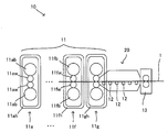
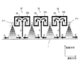
- FIG. 1 is a diagram schematically showing a part of a hot-rolled steel sheet manufacturing apparatus 10 provided with a cooling device 20 according to the first embodiment.
- the steel sheet 1 is conveyed from the left side (upstream side, upper process side) to the right side (downstream side, lower process side) of the paper surface, and the top and bottom of the paper surface is the vertical direction.
- the upstream side (upper process side) / downstream side (lower process side) direction may be described as the passing plate direction, and the direction of the plate width of the steel plate to be passed is the direction perpendicular to this direction. May be described.
- repeated reference numerals may be omitted for easy viewing.
- a hot rolled steel sheet manufacturing apparatus 10 includes a hot finish rolling mill row 11, a cooling device 20, transport rolls 12, 12,..., A pinch roll 13.
- a heating furnace, a rough rolling mill row, and the like are arranged on the upper process side from the hot finish rolling mill row 11, and the conditions of the steel sheet for entering the hot finish rolling mill row 11 are set. It is in order.
- various facilities for shipping as a steel plate coil, such as another cooling device and a winder, are arranged.
- Hot-rolled steel sheets are generally manufactured as follows. That is, the rough bar extracted from the heating furnace and rolled to a predetermined thickness by the rough rolling mill is continuously rolled to the predetermined thickness by the hot finish rolling mill row 11 while the temperature is controlled. Thereafter, it is rapidly cooled in the cooling device 20.
- the cooling device 20 is as close as possible to the rolling rolls 11gw and 11gw (see FIG. 2) of the final stand 11g inside the housing 11gh that supports the rolling roll. It is installed like that. And it passes through the pinch roll 13, is cooled to a predetermined winding temperature by another cooling device, and is wound up in a coil shape by a winder.
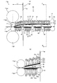
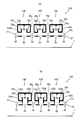
- FIG. 2 is an enlarged view of a portion of FIG. 1 where the cooling device 20 is provided.
- FIG. 2A is an enlarged view so that the entire cooling device 20 appears, and
- FIG. 2B is a view paying attention to the vicinity of the final stand 11g.
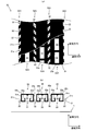
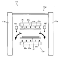
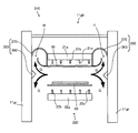
- FIG. 3 is a cross-sectional view taken along the line III-III in FIG. Accordingly, in FIG. 3, the upper and lower sides of the drawing are the vertical direction of the manufacturing apparatus 10, the left and right sides of the drawing are the steel plate width direction, and the back / front direction of the drawing is the sheet passing direction.
- each of the rolling mills 11a, 11b,..., 11g is a rolling mill that constitutes a so-called stand, and can satisfy conditions such as thickness, mechanical properties, and surface quality required for the final product. Thus, rolling conditions such as a rolling reduction are set.
- the reduction ratio of each stand is set so as to satisfy the performance that the steel sheet to be manufactured should have, but after high pressure rolling, the austenite grains are greatly deformed and the transition density is increased, thereby cooling From the viewpoint of reducing the size of the ferrite grains, it is preferable that the rolling reduction is large in the final stand 11g.
- the rolling mills of each stand were arranged so that the work rolls (11aw, 11aw,..., 11fw, 11fw, 11gw, 11gw) that are actually rolled down with the steel plate 1 sandwiched therebetween, and the outer circumferences of the work rolls were in contact with each other.
- the rolling mill includes a work roll and a backup roll inside, and includes a housing (11ah,..., 11fh, 11gh) that forms an outer shell of the rolling mill and supports the rolling roll.
- the housing has standing portions (upright portions 11gr and 11gr in FIG. 3 in the final stand 11g) which are opposed to each other. That is, as can be seen from FIG. 3, the standing portion of the housing is erected so as to sandwich the steel plate and the lower surface guide 40 in the steel plate width direction.
- the distance between the shaft center of the work roll 11gw indicated by L1 in FIG. 2A and the lower process side end face of the housing standing portions 11gr, 11gr is larger than the radius r1 of the work roll 11gw. Accordingly, a part of the cooling device 20 can be disposed at a portion corresponding to L1-r1 as described later. That is, it is possible to install a part of the cooling device 20 so as to be inserted inside the housing 11gh. Further, as shown in FIG. 3, at the portion where the cooling device 20 is inserted between the housing standing portions 11 gr, 11 gr, the housing standing portion is on the extension line in the steel plate width direction of the lower surface guide 40 of the cooling device 20. 11gr and 11gr are present as side walls. A predetermined gap is formed between the end portion of the lower surface guide 40 in the width direction of the steel plate and the housing standing portions 11gr, 11gr.
- the cooling device 20 includes upper surface water supply means 21, 21, ..., lower surface water supply means 22, 22, ..., upper surface guides 30, 30, ..., lower surface guides 40, 40, ..., and rectifying means 50, 50.
- the upper surface water supply means 21, 21,... Are means for supplying cooling water to the upper surface side of the steel plate 1, and are provided in a plurality of rows in the cooling headers 21 a, 21 a,. , And cooling nozzles 21c, 21c,... Attached to the tips of the conduits 21b, 21b,.
- the cooling header 21a is a pipe extending in the width direction of the steel plate, and such cooling headers 21a, 21a,.
- the conduit 21b is a plurality of thin pipes branched from the respective cooling headers 21a, and the open ends thereof are directed to the upper surface side of the steel plate.
- a plurality of conduits 21b, 21b,... Are provided in a comb-teeth shape along the tube length direction of the cooling header 21a, that is, in the steel plate width direction.
- a cooling nozzle 21c, 21c,... Is attached to the tip of each conduit 21b, 21b,.
- the cooling nozzles 21c, 21c,... Of the present embodiment are flat type spray nozzles capable of forming a fan-shaped cooling water jet (for example, a thickness of about 5 mm to 30 mm).
- 4 and 5 schematically show the cooling water jet formed on the steel plate surface by the cooling nozzles 21c, 21c,...
- FIG. 4 is a perspective view.
- FIG. 5 is a diagram schematically showing a collision mode when the jet collides with the steel plate surface.
- white circles represent the positions immediately below the cooling nozzles 21 c, 21 c,...
- bold lines represent the collision positions and shapes of the cooling water jets.
- FIGS. 4 and 5 show the sheet passing direction and the steel plate width direction together.
- the adjacent nozzle rows are arranged so that the positions in the steel plate width direction are shifted, and the adjacent nozzle rows and the steel plate width direction positions are the same.
- a so-called staggered arrangement is used.
- the cooling nozzles 21c, 21c,... are arranged so that the cooling water jet can pass at least twice over all positions in the steel plate width direction on the steel plate surface. That is, the point ST where the steel plate to be passed is moved along the straight arrow in FIG. At that time, the nozzle row A (A1, A2) twice, the nozzle row B twice (B1, B2), the nozzle row C twice (C1, C2), and so on.
- the passage is made twice, but the present invention is not limited to this, and the passage may be made three times or more.
- the cooling nozzles were twisted in directions opposite to each other in the nozzle rows adjacent in the sheet passing direction.
- the “uniform cooling width” for cooling the steel sheet is determined by the arrangement of the cooling nozzles. This means a size in the width direction of the steel plate that allows uniform cooling of the steel plate being conveyed due to the nature of the nozzle group to be arranged. Specifically, it often coincides with the maximum width of the steel sheet that can be manufactured in the steel sheet manufacturing apparatus. Specifically, for example, the size is indicated by RH in FIG.
- the configuration in which the cooling nozzles are twisted in directions opposite to each other in the adjacent nozzle rows as described above has been described.
- the twist angle ( ⁇ above) is not particularly limited, and can be appropriately determined from the viewpoint of required cooling capacity, accommodation of equipment arrangement, and the like.
- the present invention is not limited to this, and the cooling nozzles may be arranged in a straight line in the plate passing direction.
- the position where the upper surface water supply means 21 is provided, in particular, the position where the cooling nozzles 21c, 21c,... Should be arranged is not particularly limited. However, it is preferable to arrange it immediately after the final stand 11g in the hot finish rolling mill 11 so as to be as close as possible to the work roll 11gw of the final stand 11g from the inside of the housing 11gh of the final stand 11g. By arranging in this way, it is possible to rapidly cool the steel sheet 1 immediately after rolling by the hot finish rolling mill row 11. Moreover, the front-end
- the injection direction of the cooling water injected from the cooling water injection ports of the respective cooling nozzles 21c, 21c is inclined in the direction of the work roll 11gw rather than the vertical.
- the injection of the cooling water from the cooling nozzles 21c, 21c,... Closest to the work roll 11gw of the final stand 11g is inclined in the direction of the work roll 11gw rather than the vertical.
- the lower surface water supply means 22, 22,... Are means for supplying cooling water to the lower surface side of the steel plate 1.
- the lower surface water supply means 22, 22,... Are cooling headers 22a, 22a,..., Conduits 22b, 22b,. Are provided at the front end of the nozzles 22c, 22c,.
- the lower surface water supply means 22, 22,... are provided opposite to the upper surface water supply means 21, 21,..., And are substantially the same as the upper surface water supply means 21, 21,. The description is omitted here.
- FIG. 6 conceptually shows the upper surface guide 30.
- FIG. 6A is a view of the upper surface guide 30 as viewed from above the cooling device 20 and is partially cut away.
- FIG.6 (b) is the figure seen from the side surface side.
- FIG. 6 also shows the positions of the cooling nozzles 21c, 21c,.
- the upper surface guide 30 includes a plate-shaped guide plate 31 and drainage passage forming portions 35, 35,... Disposed on the upper surface side of the guide plate 31.
- the guide plate 31 is a plate-like member and is provided with inflow holes 32, 32,... And outflow holes 33, 33,.
- the inflow holes 32, 32, ... are provided at positions corresponding to the cooling nozzles 21c, 21c, ..., and the shape thereof also corresponds to the shape of the jet. Therefore, the inflow holes 32, 32,... Are arranged in parallel in the steel plate width direction to form an inflow hole array 32A, and the inflow hole arrays 32A, 32A,.
- the shape of the inflow hole is not particularly limited, and it may be formed so that the jet flow from the cooling nozzle does not hit the guide plate as much as possible.
- the opening shape of the inflow holes is substantially similar to the transverse cross-sectional shape of the cooling water jet (cross section orthogonal to the ejection direction axis). It is preferable.
- the outflow holes 33, 33,... are rectangular holes, and a plurality of the holes are juxtaposed in the steel plate width direction to form an outflow hole array 33A. .. Are prevented from entering the outflow holes 33, 33,... At the tip of the steel plate 1 being conveyed by leaving a part of the guide plate 31 between the outflow holes 33, 33,. ...
- the outflow hole arrays 33A, 33A,... are arranged between the inflow hole arrays 32A, 32A,. That is, in the guide plate 31, the inflow hole rows 32A and the outflow hole rows 33A are alternately arranged along the plate passing direction.
- the parallel rectangles as described above have been described as a preferable opening shape of the outflow holes 33, 33,. Thereby, a large opening area can be obtained efficiently in a limited space.
- the present invention is not limited to this, and it is only necessary that an appropriate amount of drainage can be secured and the steel plate can be prevented from being caught.
- the opening shape of the outflow hole is not limited to the above-described rectangle, and examples thereof include a circle and a trapezoid.
- invasion prevention means becomes a shape corresponding to the said opening shape.
- the outflow hole has a trapezoidal shape having an upper base and a lower base in the plate passing direction
- the steel plate intrusion preventing means can be formed in a parallelogram shape inclined from the plate passing direction.
- Fig. 7 shows a variation of the outflow hole.
- the outflow hole 33 ′ of the modified example of FIG. 7 is one long hole 33 ⁇ / b> A ′ in the plate width direction, and a net member 33 ⁇ / b> B ′ is stretched here. This also makes it possible to form an outflow hole.
- the so-called fineness of the mesh 33B ′ is preferably a mesh of 5 mm ⁇ 5 mm or more from the viewpoint that the influence of the flow of cooling water is small and foreign substances such as dust are hardly clogged.
- Backflow prevention pieces 33p, 33p are provided to prevent water that has entered the outflow holes 33, 33,... From flowing back from the outflow holes 33, 33,.
- the backflow prevention pieces 33p, 33p,... A larger amount of drainage can be secured, and drainage performance can be improved.
- the backflow prevention pieces 33p and 33p are erected substantially in parallel, but the backflow prevention pieces may be erected so that the upper end side is narrower than the lower end. Thereby, the flow-path cross-sectional area between the backflow prevention piece and the piece (35a, 35c) by which the drainage passage formation part mentioned later is erected can be ensured widely.
- the drainage passage forming portions 35, 35,... are members that have a concave cross section surrounded by the pieces 35a, 35b, 35c and extend in the steel plate width direction, as can be seen from FIG.
- the drainage passage forming portion 35 is disposed so as to cover the concave opening from the upper surface side of the guide plate 31 toward the guide plate 31. At this time, it covers so that a part of upper surface of the guide plate 31 and the outflow hole row
- a rectifying piece 36 is provided on the outflow hole row 33A side at a position directly above the outflow hole row 33A.
- the shape of the rectifying piece 36 is preferably a shape that can be rectified so as to separate the drainage impinging on the piece 35b toward the bottom surface of the drainage passage provided with the backflow prevention pieces 33p, 33p as described later.
- an inverted triangle, a trapezoid, a wedge shape, and other protruding shapes can be considered.
- the heights of the drainage passage forming portions 35, 35,... are not particularly limited, but when the inner diameter of the conduits 21b, 21b,. It is preferable that it is the range of these. This is because if the conduits 21b, 21b,... Are longer than 20d, the pressure loss is undesirably increased, and if it is shorter than 5d, the injection from the cooling nozzle may be unstable.
- the upper surface guide 30 as described above is arranged as shown in FIG.
- three upper surface guides 30, 30, and 30 are used, and these are arranged in parallel in the plate passing direction. All of the upper surface guides 30, 30, 30 are arranged so as to correspond to the height direction positions of the cooling nozzles 21c, 21c,. That is, in the present embodiment, the upper surface guide 30 closest to the final stand 11g is arranged so as to be inclined so that the end on the final stand 11g side is low and the other end side is high.
- the other two upper surface guides 30, 30 are arranged substantially parallel to the passage plate surface at a predetermined interval from the passage plate surface.
- the upper surface guide 30 it is possible to eliminate the problem that the front end portion is caught by the cooling nozzles 21c, 21c,... Furthermore, according to the upper surface guide 30, it becomes possible to appropriately discharge a large amount of cooling water supplied to the upper surface side of the steel plate.
- the cooling water supplied by the upper surface water supply means 21, 21,... Cools the steel sheet, and then a part of the cooling water flows in the width direction of the steel sheet and falls downward to be drained.
- the upper surface guide 30 can keep the accumulated water thin by providing a further drainage passage. Details are as follows.
- FIG. 8 shows a diagram for explanation.
- the reference numerals are omitted for the sake of clarity, but the corresponding elements can refer to the reference numerals in FIG.
- the cooling water flow density and the cooling water supply amount are so high that the drainage from the width direction of the steel plate cannot catch up, the water flow from the cooling nozzles 21c, 21c,.
- the cooling water sprayed on the upper surface of the steel plate 1 also moves forward and backward and collides as indicated by arrows R and R in FIG.
- the cooling water changes its direction, moves upward as indicated by an arrow S, passes through the outflow holes 33, 33,..., And collides with the piece 35b of the drainage passage forming portion 35.
- the wedge-shaped rectifying piece 36 is provided on the piece 35b as described above, and the direction of the cooling water is changed as indicated by arrows T and T.
- the rectifying piece 36 suppresses the resistance of the direction change to be low, and it is performed reliably and efficiently.
- the cooling water that has reached the upper surface side of the guide plate 31 moves in the back / front direction of FIG. 8 and is drained.
- the backflow prevention pieces 33p and 33p are provided at the edge of the outflow hole 33, the cooling water is prevented from returning from the outflow hole 33 again.
- the cooling water supplied to the upper surface side becomes a large quantity and becomes a high water quantity density by providing the further drainage means, the quantity of stagnant water can be suppressed.
- the holes for supplying the cooling water are separated from the holes for discharging, and the cooling water used for cooling due to the structure as described above collides with the cooling water that has started moving because of drainage. It can be suppressed. Thereby, water supply / drainage is performed smoothly, the thickness of the accumulated water can be reduced, and the cooling efficiency can be increased.
- the cooling unevenness the temperature unevenness in the width direction of the cooling water is preferably within ⁇ 30 ° C.
- outflow holes 33, 33,... Included in one outflow hole row 33A are arranged over the entire width direction of the steel plate of the upper surface guide 30, but the present invention is not limited to this.
- such an outflow hole may be provided only in the vicinity of the central portion in the width direction of the steel plate, where the accumulated water tends to be thick.
- a configuration for further improving the drainage may be added.
- the center in the plate width direction may be formed high, and the inclination may be provided so as to decrease toward both ends in the steel plate plate width direction. According to this, drainage easily moves to both ends of the guide plate 31 due to the height difference, and smooth drainage can be promoted.
- the upper surface guide itself is formed so as to be movable in the vertical direction, and the upper surface guide 30 is moved downward within a range that does not affect the plate so as to press against the staying water, forcing the cooling water into the drainage passage forming portion. It is good also as a structure to guide.
- the inflow holes 33, 33,... Provided in the guide plate 31 and both ends of the steel plate in the width direction, chamfering or rounding is performed on the edge portion (edge) (the edge is formed in an arc shape). Also good. Thereby, the catch of the steel plate passed through can be reduced or the smooth flow of cooling water can be promoted.
- the material of the guide plate 31 can be a general material having strength and heat resistance required as a guide, and is not particularly limited. However, for the purpose of reducing scratches and the like on the steel plate 1 when the steel plate 1 to be passed through contacts with the guide plate 31, a resin or the like that is softer than the steel plate 1 is used in a portion where problems of strength and heat resistance do not occur. Materials may be used.
- FIG. 9 shows a view corresponding to FIG. 6B among the upper surface guides 130 and 130 ′ of another form.
- FIG. 9A shows the upper surface guide 130
- FIG. 9B shows the upper surface guide 130 ′.
- members common to the upper surface guide 30 are denoted by the same reference numerals, and description thereof is also omitted.
- drainage passage forming portions 135, 135,... are formed separately from the guide plate 31. Therefore, in the drainage passage forming portions 135, 135, ..., the pieces 35a, 35a, ... and the backflow prevention pieces 33p, 33p, ... are connected by the bottom plates 135d, 135d, ..., and the pieces 35c, 35c, ... are connected to the backflow prevention pieces.
- 33p, 33p,... are connected to each other by bottom plates 135e, 135e,.
- Such an upper surface guide 130 may be used.
- the backflow prevention pieces 133 p ′, 133 p ′,... Extend to the upper surface side of the guide plate 31.
- FIG. 10 shows a view corresponding to FIG. 6B among the upper surface guides 230 and 230 ′ of still another embodiment.
- FIG. 10A shows the upper surface guide 230
- FIG. 10B shows the upper surface guide 230 ′.
- members common to the upper surface guides 30 and 130 are denoted by the same reference numerals, and description thereof is also omitted.
- drainage passage forming portions 235, 235,... are formed separately from the guide plate 31. Therefore, in the drainage passage forming portions 235, 235, ..., the pieces 35a, 35a, ... are connected to the backflow prevention pieces 233p, 233p, ...
- the bottom plates 235d, 235d, ..., and the pieces 35c, 35c, ... are backflow prevention pieces.
- the backflow prevention pieces 233p, 233p,... Extend on the upper surface side of the guide plate 31.
- the upper surface guide 230 in addition to the cooling nozzles 21c, 21c,... Between the guide plate 31 and the drainage passage forming portions 235, 235,..., Headers 21a, 21a,. Yes.
- Such an upper surface guide 230 may be used.
- the drainage passage forming portions 235 and 235 adjacent to the upper surface guide 230 are replaced by one drainage passage forming portion 235 ′.
- This also secures the drainage path indicated by T ′ in FIG. According to this, it becomes possible to increase the flow path cross-sectional area of the drainage channel (T ′).
- the upper surface guide as one example has been described above, but the upper surface guide is not limited to this, and a known upper surface guide can also be used.
- the lower surface guide 40 is a plate-like member disposed between the lower surface water supply means 22 and the steel plate 1 being conveyed. Thereby, especially when the steel plate 1 is passed through the manufacturing apparatus 10, it is possible to prevent the leading edge of the steel plate 1 from being caught by the lower surface water supply means 22, 22,.
- the lower surface guide 40 is provided with an inflow hole through which the jet flow from the lower surface water supply means 22 passes. As a result, the jet flow from the lower surface water supply means 22 passes through the lower surface guide 40 and reaches the lower surface of the steel plate, thereby enabling appropriate cooling.
- the shape of the lower surface guide 40 used here is not particularly limited, and a known lower surface guide can be used.
- Such a lower surface guide 40 is arranged as shown in FIG. In this embodiment, four lower surface guides 40, 40,... Are used and arranged between the transport rolls 12, 12, 12. Any one of the lower surface guides 40, 40,... Is arranged at a height that is not so low with respect to the upper ends of the transport rolls 12, 12,.
- the lower surface guide is not necessarily provided.
- the rectifying means 50 and 50 are a pair of plate-shaped members having an arc-shaped cross section as shown in FIG.
- Such rectifying means 50, 50 are provided with a convex side surface having an arcuate cross section facing upward. That is, in the pair of opposed rectifying means 50, 50, the interval between the upper end portions is formed narrow, and at least the lower end portion is arranged to be wider than the upper end portion.
- the upper end portion is provided in contact with or close to the upper surface guide 30.
- the lower end portion is in contact with the housing standing portions 11gr and 11gr.
- the positions where the rectifying means 50, 50 are arranged are generally as follows.
- a gap is formed between the housing standing portions 11gr and 11gr and the end portion of the upper surface guide 30 in the steel plate width direction.
- the rectifying means 50 and 50 are arranged at a position corresponding to between the upper surface guide 30 and the lower surface guide 40 in the vertical direction in the formed gap. Therefore, the cooling water supplied to the upper surface of the steel plate is a position where the water can be rectified when being separated and drained in the width direction of the steel plate as shown by arrows D and D in FIG.
- the water flowing in the width direction of the steel sheet collides with the housing standing part and moves separately in the vertical direction.
- Such a rapid change of direction contributes to flow resistance.
- the water which went up among the water which divided and moved to the upper and lower side eventually moves downward by gravity, and merges with the water which moves separately.
- This also causes flow resistance.
- the flow resistance becomes the flow resistance of the entire cooling water drainage, which is one of the causes that hinder smooth drainage.
- some of the waste water that has collided with the side wall and moved upward reaches the upper surface of the upper surface guide and becomes retained water, which is one of the causes of submergence at the tip of the cooling nozzle.
- the rectifying means 50, 50 it is possible to smoothly change the direction of the cooling water downward and guide it in the direction of drainage. Therefore, even if the amount of cooling water is increased, it is possible to suppress an increase in flow resistance and improve drainage. As a result, a high cooling capacity can be maintained, and a steel plate having excellent mechanical performance can be produced.
- the rectifying means 50 and 50 have been described by showing the case where the cross section is arcuate, but it is not necessarily arcuate, and other shapes can be used as long as the drainage can be smoothly changed as described above. It may be. This can include a non-arc-shaped curve, an inclined straight line, or a combination of straight lines.
- FIG. 3B shows a modification.
- the lower ends of the rectifying means 50 ′ and 50 ′ are arranged with a predetermined gap between the housing standing portions 11gr and 11gr.
- the water to be drained existing on the upper surface of the upper surface guide 30 is sucked in the direction indicated by the arrows D ′ and D ′ due to the ejector effect of the drainage indicated by the arrows D and D.
- the water existing on the upper surface of the upper surface guide 30 includes water flowing through the drainage path forming portion 35 of the upper surface guide 30 and water flowing backward from the inflow hole of the upper surface guide 30.
- the conveyance rolls 12, 12,... are rolls that convey the steel plate 1 in the plate direction while being a table of the steel plate 1.
- the lower surface guides 40, 40,... are arranged between the transport rolls 12, 12,.
- the pinch roll 13 also serves as a drainer and is provided on the lower process side of the cooling device 20. Thereby, it becomes possible to prevent the cooling water sprayed in the cooling device 20 from flowing out to the lower process side of the steel plate 1. Furthermore, the waviness of the steel plate 1 in the cooling device 20 can be suppressed, and in particular, the plate-passability of the steel plate 1 at the time before the front end of the steel plate 1 bites into the winder can be improved.
- the upper roll 13a is movable up and down as shown in FIG.
- a steel plate is manufactured as follows, for example, with the above-described hot-rolled steel plate manufacturing apparatus. That is, the jet of the cooling water in the cooling device 20 is stopped during the non-rolling time until the steel plate is wound by the winder and rolling of the next steel plate is started. Then, the pinch roll 13 on the lower process side of the cooling device 20 is moved to a position higher than the upper surface guide 30 of the cooling device 20 during the non-rolling time, and then rolling of the next steel plate is started. Is done. When the leading end of the next steel plate reaches the pinch roll 13, cooling by jetting of cooling water is started. Moreover, immediately after the front-end
- the length of the unsteady cooling part at the front end of the steel plate can be shortened. Furthermore, it becomes possible to stabilize the plate
- a hot-rolled steel sheet is manufactured by the hot-rolled steel sheet manufacturing apparatus 10 provided with the cooling device 20 operated in this way on the downstream side of the hot finish rolling mill row 11, a large amount of cooling water is used. Cooling becomes possible. That is, by manufacturing a hot-rolled steel sheet by such a manufacturing method, it becomes possible to manufacture a hot-rolled steel sheet having a refined structure.
- the plate passing speed in the hot finish rolling mill row 11 may be constant except for the plate start portion. Thereby, the steel plate with which mechanical strength was raised over the steel plate full length can be manufactured.
- the specific drainage performance is appropriately determined depending on the required amount of cooling heat of the steel sheet and is not particularly limited.
- rapid cooling immediately after rolling is effective, and therefore, it is preferable to supply cooling water having a high flow density. Therefore, the drainage should just ensure the drainage performance corresponding to the supply amount and flow density of the cooling water.
- the flow density of the cooling water supplied can be 10 to 25 m 3 / (m 2 ⁇ min). Larger flow density may be used.
- FIG. 11 is a view for explaining a hot-rolled steel sheet manufacturing apparatus 110 including the cooling device 120 according to the second embodiment, and corresponds to FIG. 3 of the manufacturing apparatus 10.
- the rectifying means 150 of the cooling device 120 is different from the rectifying means 50 of the cooling device 20. Since other configurations are common to the manufacturing apparatus 10, the description thereof is omitted here, and the reference numerals are also common.
- the rectifiers 150 and 150 are injection devices that inject gas as shown in FIG. Such rectifying means 150 and 150 are preferably disposed between the housing standing portions 11gr and 11gr and the end of the upper surface guide 30 while the injection ports thereof are directed downward. That is, since the cooling water supplied to the upper surface of the steel plate flows as shown by arrows E and E in FIG. 3, it is a position where gas can be injected from above to assist.
- the rectifying means 150 and 150 are used alone.
- the embodiment is not limited to this, and the rectifying means 50 and 50 in the first embodiment may be used in combination. Thereby, it becomes possible to further improve drainage performance.
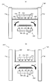
- FIG. 12 is a view for explaining the hot-rolled steel sheet manufacturing apparatuses 210 and 210 ′ including the cooling apparatuses 220 and 220 ′ according to the third embodiment, and corresponds to FIG. 3 of the manufacturing apparatus 10.
- FIG. 12A shows the manufacturing apparatus 210
- FIG. 12B shows the manufacturing apparatus 210 '.
- the rectifying means 250 and 250 ′ of the cooling apparatuses 220 and 220 ′ are different from the rectifying means 50 of the cooling apparatus 20. Since other configurations are common to the manufacturing apparatus 10, the description thereof is omitted here, and the reference numerals are also common.
- the rectifying means 250, 250 are provided so as to close the space between the upper surface guide 30 and the housing standing portions 11gr, 11gr.
- the rectifying means 250 ′ and 250 ′ are provided so as to extend upward from both ends in the width direction of the upper surface guide 30.
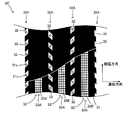
- FIG. 13 is a view for explaining a hot-rolled steel sheet manufacturing apparatus 310 including the cooling apparatus 320 according to the fourth embodiment, and corresponds to FIG. 3 of the manufacturing apparatus 10.
- the rectifying means 350 of the cooling device 320 is different from the rectifying means 50 of the cooling device 20. Since other configurations are common to the manufacturing apparatus 10, the description thereof is omitted here, and the reference numerals are also common.
- the rectifying means 350 and 350 include a diversion means 360 and 360 and a drainage means 370 and 370.
- the diversion means 360 and 360 are long members having a wedge-shaped cross section, and have a wedge-shaped cross section as shown in FIG. 13 and extend in the threading direction.
- the diversion means 360, 360 are preferably provided on the surfaces of the housing standing portions 11gr, 11gr that collide when the cooling water supplied to the upper surface of the steel plate moves in the width direction of the steel plate.
- the drainage means 370 and 370 are members in which tubular members are arranged in the longitudinal direction as the plate passing direction. Moreover, as can be seen from FIG. 13, openings H and H are provided in a part of the tube wall. Such draining means 370 and 370 are disposed between the end portion of the upper surface guide 30 and the housing standing portions 11gr and 11gr.
- the cooling water supplied to the upper surface of the steel sheet flows toward both sides in the width direction of the steel sheet for drainage. Then, the drainage is divided into upper and lower parts by suppressing the flow resistance due to the wedge-shaped effect of the diverting means 360 and 360.
- the drainage flowing downward is drained as indicated by G and G in FIG.
- the waste water moved upward by the flow dividing means 360, 360 flows as indicated by G ', G' in FIG. 13 and enters the pipe through the openings H, H of the drain means 370, 370. Drainage that enters the pipe moves in the length direction of the pipe and is appropriately drained from other locations.
- the water flowing in the width direction of the steel sheet is divided and moved in the vertical direction while the flow resistance is suppressed by the diversion means 360, 360. Also, of the water that has been moved up and down, the water that has risen above is collected and drained by the draining means 370 and 370 without returning downward due to gravity. Therefore, it is possible to prevent the flow resistance caused by the water that has moved upward again moving downward.
- the upright portion of the final stand has been described as the side wall that exists outside the cooling device, but the side wall is not limited to this, and is related to the arrangement with other devices. It may be a side wall by the other device that occurs.
- the drainage properties of the examples shown in FIGS. 3A (No. 1), 12A (No. 2), and 13 (No. 3) were examined. Moreover, it investigated similarly about the example (comparative example, No. 4) which is not provided with a rectification
- the plate width of the steel plate to be passed through which has a length equal to the uniform cooling width is 1.6 m, and the distance between the uniform cooling width direction end portion of the steel plate and the housing standing portion is 0.2 m and 0.4 m. Two types were used.
- the flow rate density of the cooling water is 20 (m 3 / (m 2 ⁇ min)).
- the drainage evaluation is based on whether or not the cooling nozzle is submerged.
- the case where the cooling nozzle is submerged is “x”, and the case where the cooling nozzle is submerged or not is so-called “submerged”. It was.
- a case where a small amount of cooling water stays on the upper surface guide but the cooling nozzle is not submerged is indicated by “ ⁇ ”, and a case where no cooling water stays on the upper surface guide is indicated by “ ⁇ ”.
- Table 1 The results are shown in Table 1.
Landscapes
- Engineering & Computer Science (AREA)
- Mechanical Engineering (AREA)
- Metal Rolling (AREA)
Abstract
Description
また、「冷却水」とは、冷却媒体としての冷却水であり、いわゆる純水であることを要せず、工業用水等、不可避に混入する不純物を含んでいても良い水を意味する。
10、110、210、210’、310 製造装置
11 圧延機列
11g 最終スタンド
11gh ハウジング
11gr (ハウジング)立設部(側壁)
12 搬送ロール
13 ピンチロール
20、120、220、220’、320 冷却装置
21 上面給水手段
21a 冷却ヘッダ
21b 導管
21c 冷却ノズル
22 下面給水手段
22a 冷却ヘッダ
22b 導管
22c 冷却ノズル
30、30’、130、130’、230、230’ 上面ガイド
40 下面ガイド
50、150、250、、250’、350 整流手段
各スタンドの圧延機は、実際に鋼板1を挟んで圧下する一対のワークロール(11aw、11aw、…、11fw、11fw、11gw、11gw)と、該ワークロールに外周同士を接するように配置された一対のバックアップロール(11ab、11ab、…、11fb、11fb、11gb、11gb)とを有している。また、圧延機はワークロール及びバックアップロールを内側に含み、圧延機の外殻を形成し、圧延ロールを支持するハウジング(11ah、…、11fh、11gh)を備えている。該ハウジングは対向して立設された立設部(最終スタンド11gにおいては図3の立設部11gr、11gr)を有している。すなわち、ハウジングの立設部は、図3からわかるように、鋼板及び下面ガイド40を鋼板板幅方向に挟むように立設されている。
また、図3に示すように、冷却装置20がハウジング立設部11gr、11grの間に挿入された部位において、冷却装置20の下面ガイド40の鋼板板幅方向の延長線上にはハウジング立設部11gr、11grが側壁として存在する。そして当該下面ガイド40の鋼板板幅方向端部とハウジング立設部11gr、11grとの間には所定の間隙が形成されている。
本実施形態では、図2、図3からわかるように冷却ヘッダ21aは鋼板板幅方向に延在する配管であり、このような冷却ヘッダ21a、21a、…が通板方向に並列されている。
導管21bは各冷却ヘッダ21aから分岐する複数の細い配管であり、その開口端部が鋼板上面側に向けられている。導管21b、21b、…は、冷却ヘッダ21aの管長方向に沿って、すなわち鋼板板幅方向に複数、櫛歯状に設けられている。
図4、図5からわかるように本実施形態では、隣り合うノズル列では、鋼板板幅方向の位置をずらすように配置し、さらにその隣のノズル列と鋼板板幅方向位置が同じとなるように、いわゆる千鳥状配列としている。
L=2PW/cosβ
の関係が成り立つように、冷却ノズル21c、21c、…を配置した。ここでは2回通過としたが、これに限定されることはなく、3回以上通過するように構成してもよい。なお、鋼板板幅方向における冷却能の均一化を図るという観点から、通板方向で隣り合うノズル列では、互いに逆の方向に冷却ノズルを捻った。
また、本実施形態では、上記利点の観点から通板方向に隣り合うノズル列を千鳥状配列とする形態とした。しかしながら、これに限定されるものではなく、冷却ノズルが通板方向に直線上に並列される形態であってもよい。
流入孔32、32、…は上記した冷却ノズル21c、21c、…に対応する位置に設けられ、その形状も噴流の形状に対応するものとしている。従って、流入孔32、32、…は、鋼板板幅方向に並列されて流入孔列32Aを形成するとともに、該流入孔列32A、32A、…が通板方向にさらに並列されている。ここで、流入孔の形状は特に限定されるものではなく、冷却ノズルからの噴流がガイド板にできるだけ当たらないように形成されていればよい。具体的には使用される冷却ノズルの噴流の特性にもよるが、1つの冷却ノズル21cからの単位時間当りの冷却水噴出量の10%以上が上面ガイド30のガイド板31に衝突しないように通過する形状であることが好ましい。さらに限られたスペースに効率よく当該流入孔32、32、…を設ける観点から、流入孔の開口形状は、冷却水噴流の横断面形状(噴出方向軸に直交する断面)に略相似形であることが好ましい。
すなわち、ガイド板31では通板方向に沿って流入孔列32Aと流出孔列33Aとが交互に配置されている。
本実施形態では逆流防止片33p、33pは略平行に立設されているが、逆流防止片を、その下端より上端側が狭くなるように立設させてもよい。これにより、逆流防止片と後述する排水通路形成部の立設される片(35a、35c)との間の流路断面積を広く確保することができる。
また、流出孔列33Aに対向する片35bのうち、流出孔列33A側には該流出孔列33Aの真上となる位置に整流片36が設けられている。整流片36の形状は、片35bに衝突する排水を後述するように逆流防止片33p、33pが設けられた排水通路の底面方向へ分離するように整流化できる形状が好ましい。例えば、逆三角形、台形、楔型やその他突起型形状が考えられる。
さらに、上面ガイド30によれば、鋼板上面側に供給された大量の冷却水を適切に排出することが可能となる。第一に、上面給水手段21、21、…により供給された冷却水は鋼板を冷却した後その一部は鋼板板幅方向に流れ、下方に落下して排水される。しかしながら供給された冷却水量、流量密度が大きいと当該排水では追い付かずに滞留水が厚く形成されてしまう。これに対して上面ガイド30ではさらなる排水通路を設けることにより滞留水を薄く維持することが可能となる。詳しくは次の通りである。
これによりガイド板31の上面側に達した冷却水は図8の紙面奥/手前方向に移動して排水される。このとき流出孔33の縁には逆流防止片33p、33pが設けられているので、再び流出孔33から冷却水が戻ることを抑制している。
このように円滑な排水と滞留水の抑制により鋼板板幅方向における冷却ムラを小さく抑えることも可能となる。これにより均一な品質を有する鋼板を得ることができる。冷却ムラは、冷却水の板幅方向温度ムラが±30℃以内であることが好ましい。
ガイド板31の上面側のうち板幅方向中央を高く形成し、鋼板板幅方向両端に向けて低くなるように傾斜を設けても良い。これによれば高低差により、排水がガイド板31の両端に移動しやすくなり、さらに円滑な排水を促進することができる。
また、ポンプ等を設置して強制的に排水させることや、排水通路形成部内を負圧にすることにより冷却水を排水通路形成部内に導入しやすくし、さらに排水性を向上させてもよい。
また、上面ガイド自体を上下方向に移動可能に形成し、上面ガイド30を通板に影響を与えない範囲で下方に移動することで滞留水に押しつけ、強制的に排水通路形成部内に冷却水を導く構成としてもよい。
上面ガイド130では、排水通路形成部135、135、…がガイド板31から分離して形成されている。従って、排水通路形成部135、135、…では、片35a、35a、…と逆流防止片33p、33p、…とが底板135d、135d、…により連結され、片35c、35c、…と逆流防止片33p、33p、…とが底板135e、135e、…により連結され、排水通路の底部を形成している。このような上面ガイド130としてもよい。
上面ガイド130’では、さらに逆流防止片133p’、133p’、…がガイド板31の上面側に延在している形態である。
上面ガイド230でも、排水通路形成部235、235、…がガイド板31から分離して形成されている。従って、排水通路形成部235、235、…では、片35a、35a、…と逆流防止片233p、233p、…とが底板235d、235d、…により連結され、片35c、35c、…と逆流防止片233p、233p、…とが底板235e、235e、…により連結され、底板235d、235d、…及び底板235e、235e、…が排水通路の底部を形成している。また、逆流防止片233p、233p、…がガイド板31の上面側に延在している。上面ガイド230では、ガイド板31と排水通路形成部235、235、…との間に冷却ノズル21c、21c、…の他、ヘッダ21a、21a、…及び導管21b、21b、…もここに含んでいる。このような上面ガイド230としてもよい。
また、整流手段50、50が配置される位置は概ね次のような位置である。すなわち、鋼板板幅方向にはハウジング立設部11gr、11grと上面ガイド30端部との間に間隙が形成される。整流手段50、50は、この形成された間隙のうち、鉛直方向については上面ガイド30と下面ガイド40との間に相当する位置に配置される。従って、鋼板上面に供給された冷却水が、図3に矢印D、Dに示したように、鋼板板幅方向に分かれて排水される際にその水を整流することができる位置である。
このように上面ガイド30の上面に存する水としては、上記した上面ガイド30の排水経路形成部35を流れる水や、上面ガイド30の流入孔から逆流してきた水を挙げることができる。
当該次の鋼板の先端がピンチロール13に到達したときに冷却水の噴射による冷却を開始する。また、鋼板1の先端がピンチロール13を通過した直後に上側ロール13aを下降させ、鋼板1のピンチを開始する。
従って、このように操業される冷却装置20を熱間仕上げ圧延機列11の下流側に備える熱延鋼板の製造装置10により、熱延鋼板を製造すれば、高密度、大量の冷却水を用いて冷却することが可能になる。すなわち、かかる製造方法により熱延鋼板を製造することで、組織が微細化された熱延鋼板を製造することが可能になる。
すなわち、鋼板上面に供給された冷却水が、図3に矢印E、Eに示したように流れるために、その上方から気体を噴射して補助することができる位置である。
分流手段360、360は楔形断面を有した長尺部材で、図13に示したような楔形断面を有して通板方向に延在する。分流手段360、360は、鋼板上面に供給された冷却水が鋼板板幅方向に移動したときに衝突するハウジング立設部11gr、11gr面に設けられることが好ましい。
排水手段370、370は、管状の部材がその長手方向を通板方向として配置された部材である。また、管壁の一部には図13からわかるように開口部H、Hが設けられている。このような排水手段370、370は、上面ガイド30端部とハウジング立設部11gr、11grとの間に配置されている。

Claims (12)
- 熱間仕上げ圧延機列の最終スタンドの下工程側に配置され、搬送ロール上を搬送される鋼板を冷却可能に設けられた複数の冷却ノズルを備える鋼板の冷却装置であって、
前記冷却ノズルは、前記鋼板が通過する部位の上面側及び下面側となる位置に設けられて前記鋼板が通過する部位に向けて冷却水を噴射可能とされ、
前記冷却ノズルによる均一冷却幅より前記鋼板の板幅方向外側となる位置に前記冷却ノズルから噴射された冷却水の排水を整流可能に設けられた整流手段を有する冷却装置。 - 前記鋼板が通過する部位の前記上面側には上面ガイドが設けられ、
前記整流手段は前記冷却ノズルによる均一冷却幅より前記鋼板の板幅方向外側となる位置の一方及び他方に設けられた対向する一対の部材であり、該対向する部材の間隔は、上端で最も狭く、下端で前記上端より広くなるように配置され、上端は前記上面ガイドに接触、又は近接して設けられ、下端は前記上面ガイドより下方に位置することを特徴とする請求の範囲第1項に記載の冷却装置。 - 前記整流手段は、前記冷却ノズルから噴射された冷却水が前記上面ガイドの幅方向両端の外側から該上面ガイドの上面に達することを防止する手段であることを特徴とする請求の範囲第1項又は第2項に記載の冷却装置。
- 前記整流手段は、下方に気体を噴射する気体噴射装置を備えることを特徴とする請求の範囲第1項~第3項に記載の冷却装置。
- 前記整流手段は、前記排水を上方と下方とに分岐して導水する分岐手段と、前記上方に分岐されて導水された水が流入可能な開口を具備する排水手段と、を有する請求の範囲第1項に記載の冷却装置。
- 熱間仕上げ圧延機列、及び請求の範囲第1項~第5項のいずれか一項に記載の冷却装置を具備する熱延鋼板の製造装置であって、
前記冷却装置より前記鋼板の板幅方向外側となる位置には側壁が立設している熱延鋼板の製造装置。 - 前記熱間仕上げ圧延機列の最終スタンドは、ワークロールを保持するハウジングを備え、前記ハウジングは、間に前記上面ガイドの一部を含む一対の立設部を有しており、該立設部が前記側壁である請求の範囲第6項に記載の熱延鋼板の製造装置。
- 熱間仕上げ圧延機列、及び請求の範囲第1項~第5項のいずれか一項に記載の冷却装置を具備する熱延鋼板の製造装置であって、
前記冷却装置より前記鋼板の板幅方向外側となる位置には側壁が立設しており、前記冷却装置の前記整流手段の少なくとも一部が前記側壁に接触して設けられていることを特徴とする熱延鋼板の製造装置。 - 熱間仕上げ圧延機列、及び請求の範囲第1項~第5項のいずれか一項に記載の冷却装置を具備する熱延鋼板の製造装置であって、
前記冷却装置より前記鋼板の板幅方向外側となる位置には側壁が立設しており、前記冷却装置の前記整流手段が前記側壁と間隙を有して設けられていることを特徴とする熱延鋼板の製造装置。 - 請求の範囲第6項~第9項のいずれか一項に記載の熱延鋼板の製造装置に通板することにより鋼板を製造する鋼板の製造方法。
- 請求の範囲第6項~第9項のいずれか一項に記載の熱延鋼板の製造装置に通板することにより鋼板を製造する方法であって、
前記熱間仕上げ圧延機列のうち前記最終スタンドの圧下率を最も大きくして仕上げ圧延する工程と、
前記冷却装置により冷却する工程と、を含む、鋼板の製造方法。 - 請求の範囲第6項~第9項のいずれか一項に記載の熱延鋼板の製造装置に通板することにより鋼板を製造する方法であって、
前記製造装置は前記冷却装置の下工程側にピンチロールを備え、
通板される板の先端部が前記ピンチロールに達した後に前記冷却装置による冷却を開始する鋼板の製造方法。
Priority Applications (2)
| Application Number | Priority Date | Filing Date | Title |
|---|---|---|---|
| KR1020117028076A KR101337815B1 (ko) | 2009-06-30 | 2010-06-22 | 강판의 냉각 장치, 열연 강판의 제조 장치, 및 강판의 제조 방법 |
| CN201080023525.7A CN102448631B (zh) | 2009-06-30 | 2010-06-22 | 钢板的冷却装置、热轧钢板的制造装置和钢板的制造方法 |
Applications Claiming Priority (2)
| Application Number | Priority Date | Filing Date | Title |
|---|---|---|---|
| JP2009156030A JP4674646B2 (ja) | 2009-06-30 | 2009-06-30 | 鋼板の冷却装置、熱延鋼板の製造装置、及び鋼板の製造方法 |
| JP2009-156030 | 2009-06-30 |
Publications (1)
| Publication Number | Publication Date |
|---|---|
| WO2011001849A1 true WO2011001849A1 (ja) | 2011-01-06 |
Family
ID=43410926
Family Applications (1)
| Application Number | Title | Priority Date | Filing Date |
|---|---|---|---|
| PCT/JP2010/060566 WO2011001849A1 (ja) | 2009-06-30 | 2010-06-22 | 鋼板の冷却装置、熱延鋼板の製造装置、及び鋼板の製造方法 |
Country Status (5)
| Country | Link |
|---|---|
| JP (1) | JP4674646B2 (ja) |
| KR (1) | KR101337815B1 (ja) |
| CN (1) | CN102448631B (ja) |
| TW (1) | TWI446975B (ja) |
| WO (1) | WO2011001849A1 (ja) |
Cited By (1)
| Publication number | Priority date | Publication date | Assignee | Title |
|---|---|---|---|---|
| EP2735383A1 (en) * | 2011-07-21 | 2014-05-28 | Nippon Steel & Sumitomo Metal Corporation | Cooling device, hot-rolled steel sheet manufacturing apparatus, and hot-rolled steel sheet manufacturing method |
Families Citing this family (3)
| Publication number | Priority date | Publication date | Assignee | Title |
|---|---|---|---|---|
| CN105363799B (zh) * | 2015-10-21 | 2017-11-17 | 钢铁研究总院 | 一种组织与性能均匀化钢材的非均温控轧控冷工艺 |
| CN111744973A (zh) * | 2019-03-27 | 2020-10-09 | 杰富意钢铁株式会社 | 棒钢的冷却方法和冷却雾的喷吹装置、以及棒钢的制造方法 |
| CN112857063B (zh) * | 2021-01-15 | 2022-04-22 | 江苏骏茂新材料科技有限公司 | 一种钢板生产传送带用顶置水冷装置 |
Citations (8)
| Publication number | Priority date | Publication date | Assignee | Title |
|---|---|---|---|---|
| JPH0570712U (ja) * | 1992-02-21 | 1993-09-24 | 新日本製鐵株式会社 | 熱間圧延材の上部冷却装置 |
| JPH0938713A (ja) * | 1995-07-31 | 1997-02-10 | Kawasaki Steel Corp | 鋼板の均一冷却方法 |
| JPH10216823A (ja) * | 1997-02-05 | 1998-08-18 | Nkk Corp | 高温鋼板の冷却装置 |
| JPH11708A (ja) * | 1997-04-10 | 1999-01-06 | Nippon Steel Corp | 圧延鋼板の均一冷却方法 |
| JP2005206917A (ja) * | 2004-01-26 | 2005-08-04 | Nisshin Steel Co Ltd | 材質安定性に優れた高強度合金化溶融亜鉛めっき原板用熱延鋼帯,溶融亜鉛めっき鋼帯および製造法 |
| WO2007099676A1 (ja) * | 2006-03-03 | 2007-09-07 | Jfe Steel Corporation | 熱延鋼帯の冷却装置および冷却方法 |
| JP4029871B2 (ja) * | 2004-07-22 | 2008-01-09 | 住友金属工業株式会社 | 鋼板の冷却装置、熱延鋼板の製造装置及び製造方法 |
| JP2010064097A (ja) * | 2008-09-10 | 2010-03-25 | Jfe Steel Corp | 鋼材の冷却設備 |
Family Cites Families (6)
| Publication number | Priority date | Publication date | Assignee | Title |
|---|---|---|---|---|
| FR2580199B1 (fr) * | 1985-04-15 | 1988-09-09 | Siderurgie Fse Inst Rech | Procede et dispositif de reglage de la largeur d'un rideau de liquide |
| JPH0429871A (ja) * | 1990-05-25 | 1992-01-31 | Seiko Epson Corp | 印刷装置 |
| JP3145144B2 (ja) * | 1991-09-10 | 2001-03-12 | 大日本塗料株式会社 | 型内被覆組成物 |
| WO2004014577A1 (ja) * | 2002-08-08 | 2004-02-19 | Jfe Steel Corporation | 熱延鋼帯の冷却装置、熱延鋼帯の製造方法および熱延鋼帯の製造ライン |
| CN100404154C (zh) * | 2003-06-13 | 2008-07-23 | 杰富意钢铁株式会社 | 用于钢板的加速控制冷却工艺,其生产的钢板,以及冷却设备 |
| JP4029865B2 (ja) | 2004-06-04 | 2008-01-09 | 住友金属工業株式会社 | 熱延鋼板の製造設備及び熱延鋼板の製造方法 |
-
2009
- 2009-06-30 JP JP2009156030A patent/JP4674646B2/ja active Active
-
2010
- 2010-06-22 WO PCT/JP2010/060566 patent/WO2011001849A1/ja active Application Filing
- 2010-06-22 CN CN201080023525.7A patent/CN102448631B/zh active Active
- 2010-06-22 KR KR1020117028076A patent/KR101337815B1/ko active IP Right Grant
- 2010-06-29 TW TW099121240A patent/TWI446975B/zh active
Patent Citations (8)
| Publication number | Priority date | Publication date | Assignee | Title |
|---|---|---|---|---|
| JPH0570712U (ja) * | 1992-02-21 | 1993-09-24 | 新日本製鐵株式会社 | 熱間圧延材の上部冷却装置 |
| JPH0938713A (ja) * | 1995-07-31 | 1997-02-10 | Kawasaki Steel Corp | 鋼板の均一冷却方法 |
| JPH10216823A (ja) * | 1997-02-05 | 1998-08-18 | Nkk Corp | 高温鋼板の冷却装置 |
| JPH11708A (ja) * | 1997-04-10 | 1999-01-06 | Nippon Steel Corp | 圧延鋼板の均一冷却方法 |
| JP2005206917A (ja) * | 2004-01-26 | 2005-08-04 | Nisshin Steel Co Ltd | 材質安定性に優れた高強度合金化溶融亜鉛めっき原板用熱延鋼帯,溶融亜鉛めっき鋼帯および製造法 |
| JP4029871B2 (ja) * | 2004-07-22 | 2008-01-09 | 住友金属工業株式会社 | 鋼板の冷却装置、熱延鋼板の製造装置及び製造方法 |
| WO2007099676A1 (ja) * | 2006-03-03 | 2007-09-07 | Jfe Steel Corporation | 熱延鋼帯の冷却装置および冷却方法 |
| JP2010064097A (ja) * | 2008-09-10 | 2010-03-25 | Jfe Steel Corp | 鋼材の冷却設備 |
Cited By (2)
| Publication number | Priority date | Publication date | Assignee | Title |
|---|---|---|---|---|
| EP2735383A1 (en) * | 2011-07-21 | 2014-05-28 | Nippon Steel & Sumitomo Metal Corporation | Cooling device, hot-rolled steel sheet manufacturing apparatus, and hot-rolled steel sheet manufacturing method |
| EP2735383A4 (en) * | 2011-07-21 | 2015-04-15 | Nippon Steel & Sumitomo Metal Corp | COOLING DEVICE, DEVICE FOR PREPARING A HOT-ROLLED STEEL PLATE AND METHOD FOR PRODUCING A HOT-ROLLED STEEL PLATE |
Also Published As
| Publication number | Publication date |
|---|---|
| TW201114513A (en) | 2011-05-01 |
| TWI446975B (zh) | 2014-08-01 |
| JP2011011218A (ja) | 2011-01-20 |
| CN102448631B (zh) | 2016-08-17 |
| KR20120023702A (ko) | 2012-03-13 |
| JP4674646B2 (ja) | 2011-04-20 |
| CN102448631A (zh) | 2012-05-09 |
| KR101337815B1 (ko) | 2013-12-06 |
Similar Documents
| Publication | Publication Date | Title |
|---|---|---|
| JP4678448B2 (ja) | 熱延鋼板の製造装置、及び鋼板の製造方法 | |
| JP4788851B2 (ja) | 鋼板の冷却装置、熱延鋼板の製造装置及び製造方法 | |
| JP5573837B2 (ja) | 熱延鋼板の冷却装置、冷却方法、製造装置、及び、製造方法 | |
| KR101514932B1 (ko) | 냉각 장치, 열연 강판의 제조 장치, 및 열연 강판의 제조 방법 | |
| WO2011001849A1 (ja) | 鋼板の冷却装置、熱延鋼板の製造装置、及び鋼板の製造方法 | |
| JP5673530B2 (ja) | 熱延鋼板の冷却装置、冷却方法、製造装置、及び、製造方法 | |
| JP5458699B2 (ja) | 鋼板の冷却装置、熱延鋼板の製造装置及び製造方法 | |
| JP2002239623A (ja) | 熱延鋼帯の冷却装置 | |
| JP6074197B2 (ja) | 鋼板の冷却装置、熱延鋼板の製造装置、及び熱延鋼板の製造方法 | |
| JP5613997B2 (ja) | 熱延鋼板の冷却装置、熱延鋼板の製造装置及び製造方法 | |
| JP5421892B2 (ja) | 鋼板の冷却装置、熱延鋼板の製造装置及び製造方法 | |
| WO2012043210A1 (ja) | 熱延鋼板の製造装置 |
Legal Events
| Date | Code | Title | Description |
|---|---|---|---|
| WWE | Wipo information: entry into national phase |
Ref document number: 201080023525.7 Country of ref document: CN |
|
| 121 | Ep: the epo has been informed by wipo that ep was designated in this application |
Ref document number: 10794019 Country of ref document: EP Kind code of ref document: A1 |
|
| DPE1 | Request for preliminary examination filed after expiration of 19th month from priority date (pct application filed from 20040101) | ||
| WWE | Wipo information: entry into national phase |
Ref document number: 9024/DELNP/2011 Country of ref document: IN |
|
| ENP | Entry into the national phase |
Ref document number: 20117028076 Country of ref document: KR Kind code of ref document: A |
|
| NENP | Non-entry into the national phase |
Ref country code: DE |
|
| 122 | Ep: pct application non-entry in european phase |
Ref document number: 10794019 Country of ref document: EP Kind code of ref document: A1 |