WO2011001504A1 - Dispositif de dessin et procédé de dessin - Google Patents
Dispositif de dessin et procédé de dessin Download PDFInfo
- Publication number
- WO2011001504A1 WO2011001504A1 PCT/JP2009/061917 JP2009061917W WO2011001504A1 WO 2011001504 A1 WO2011001504 A1 WO 2011001504A1 JP 2009061917 W JP2009061917 W JP 2009061917W WO 2011001504 A1 WO2011001504 A1 WO 2011001504A1
- Authority
- WO
- WIPO (PCT)
- Prior art keywords
- pointer
- data
- area
- function
- image
- Prior art date
Links
Images


Classifications
-
- G—PHYSICS
- G06—COMPUTING; CALCULATING OR COUNTING
- G06T—IMAGE DATA PROCESSING OR GENERATION, IN GENERAL
- G06T11/00—2D [Two Dimensional] image generation
- G06T11/60—Editing figures and text; Combining figures or text
-
- G—PHYSICS
- G06—COMPUTING; CALCULATING OR COUNTING
- G06F—ELECTRIC DIGITAL DATA PROCESSING
- G06F3/00—Input arrangements for transferring data to be processed into a form capable of being handled by the computer; Output arrangements for transferring data from processing unit to output unit, e.g. interface arrangements
- G06F3/01—Input arrangements or combined input and output arrangements for interaction between user and computer
- G06F3/048—Interaction techniques based on graphical user interfaces [GUI]
- G06F3/0484—Interaction techniques based on graphical user interfaces [GUI] for the control of specific functions or operations, e.g. selecting or manipulating an object, an image or a displayed text element, setting a parameter value or selecting a range
- G06F3/04845—Interaction techniques based on graphical user interfaces [GUI] for the control of specific functions or operations, e.g. selecting or manipulating an object, an image or a displayed text element, setting a parameter value or selecting a range for image manipulation, e.g. dragging, rotation, expansion or change of colour
Definitions
- the present invention relates to a drawing technique.
- a desired drawing form such as a pencil, a brush, and a spray can be selected, and various drawing effects such as blurring and gradation can be added.
- the user needs to frequently move the pointer (cursor) such as selecting a desired drawing function, drawing designation in the drawing area, and switching of the drawing function, and the operation tends to be complicated. there were.
- pointer cursor
- One cause of the problem is that the user interface of the conventional drawing application is realized by using one pointer. Also in the graphic processing apparatus using the first cursor and the second cursor described above, only the second cursor is designated for drawing, and the first cursor is used for designating drawing information.
- drawing work may be performed with both hands.
- the pattern is drawn along the pattern by supporting the pattern with one hand and spraying with the other hand.
- such a drawing operation using both hands has not been realized.
- an object of one embodiment of the present invention is to provide a drawing technique that improves the operability of drawing.
- the first aspect relates to a drawing apparatus.
- the drawing apparatus includes pointer control means for detecting each operation using the first pointer and the second pointer in the drawing area, the first drawing function designated for the first pointer, and the first First generation means for generating first drawing data according to an operation in the drawing area using the pointer, a second drawing function designated for the second pointer, and the drawing area using the second pointer
- a second generating means for generating second drawing data according to the operation of the first drawing function, and a drawing effect corresponding to the first drawing function or the second drawing function is applied to a drawing portion where the first drawing data and the second drawing data overlap.
- Drawing means for generating the drawn data includes pointer control means for detecting each operation using the first pointer and the second pointer in the drawing area, the first drawing function designated for the first pointer, and the first First generation means for generating first drawing data according to an operation in the drawing area using the pointer, a second drawing function designated for the second pointer, and the drawing area using the second pointer
- FIG. 1 is a diagram illustrating a hardware configuration example of a drawing apparatus according to the first embodiment.
- FIG. 2 is a block diagram illustrating a processing configuration example of the drawing apparatus according to the first embodiment.
- FIG. 3 is a diagram illustrating an example of the operation screen.
- FIG. 4 is a diagram illustrating an example of a drawing setting table.
- FIG. 5 is a diagram showing the concept of the drawing data generation process.
- FIG. 6 is a flowchart illustrating an operation example of the drawing apparatus according to the first embodiment.
- FIG. 7 is a diagram illustrating a drawing example 1 using the drawing apparatus according to the first embodiment.
- FIG. 8 is a diagram illustrating a drawing example 2 using the drawing apparatus according to the first embodiment.
- FIG. 9 is a diagram illustrating a drawing example 3 using the drawing apparatus according to the first embodiment.
- FIG. 10 is a diagram illustrating a hardware configuration example of the drawing apparatus according to the modification.
- FIG. 11 is a diagram illustrating a hardware configuration example of a drawing apparatus according to a modification.
- FIG. 1 is a diagram illustrating a hardware configuration example of a drawing apparatus according to the first embodiment.
- the drawing apparatus 1 according to the first embodiment includes a main unit 10 and a user interface unit as a hardware configuration.
- the main unit 10 includes a CPU (Central Processing System) 11, a RAM (Random Access Memory) 12, a hard disk drive (hereinafter referred to as HDD) 13, a user interface controller (hereinafter referred to as UI controller) 14, and the like.
- the CPU 11, RAM 12, HDD 13, and UI controller 14 are connected by a bus 15.
- the touch panel unit 18 is applied to the user interface unit in the first embodiment.
- the drawing apparatus 1 according to the first embodiment may be realized by a general-purpose computer such as a personal computer having such a hardware configuration, or may be realized by a dedicated computer. This embodiment does not limit the hardware configuration of the drawing apparatus 1.
- the touch panel unit 18 includes a display unit, a touch panel that receives user operations, a control unit, and the like.
- the touch panel unit 18 displays an image corresponding to the drawing data sent from the main unit 10 on the display unit, and obtains an input from the user by sensing an external contact with the touch panel.
- the touch panel unit 18 sends the acquired input information to the main unit 10.
- This input information includes position information (coordinate information) corresponding to the contact position on the panel, operation information corresponding to the contact state, and the like.
- the operation information here includes an operation in which the user touches the touch panel (hereinafter referred to as a touch operation), an operation in which the user releases the touch panel (hereinafter referred to as a release operation), and a touch of the user while touching the panel.
- Information that can identify an operation of moving a location hereinafter referred to as a drag operation
- the position information and the operation information are generated by the control unit in the touch panel unit 18.
- the control unit of the touch panel unit 18 refers to a signal indicating a contact position that is sequentially output from the touch panel at a predetermined cycle (sampling cycle or the like), and determines each operation based on this signal.
- the control unit detects the occurrence of a touch operation when receiving a signal indicating contact.
- a control part detects generation
- the touch panel unit 18 can sense simultaneous contact at a plurality of different positions. For example, even when the user touches different positions on the touch panel with both hands, the touch panel unit 18 senses contact at each position and sends each input information indicating each contact to the main unit 10. For example, the main unit 10 can determine that simultaneous contact at a plurality of positions has occurred when a plurality of pieces of input information are included in the information received at one time.
- the UI controller 14 is connected to the touch panel 18, transmits drawing data to the touch panel unit 18, and receives input information and operation information from the touch panel unit 18.
- the interface between the touch panel unit 18 and the main unit 10 is not limited.
- the CPU 11 is one or a plurality of processors and operates using peripheral circuits such as a RAM 12, a ROM (not shown), an interface circuit (not shown), an HDD 13, and the like.
- FIG. 2 is a block diagram illustrating a processing configuration example of the drawing apparatus according to the first embodiment.
- the drawing apparatus 1 according to the first embodiment includes an operation screen control unit 24, an operation determination unit 25, a first drawing data generation unit (hereinafter referred to as a first generation unit) 26, a second drawing data generation unit (hereinafter referred to as a second drawing data generation unit). 27), a drawing data generation unit 28, and the like.
- These processing units may be realized as hardware components, or may be realized as software components by executing a program stored in the HDD 13 or ROM (not shown) by the CPU 11 ([[ See the “Others” section).
- FIG. 2 shows an example in which each processing unit is realized as a software component.
- an OS Operating System
- the OS 20 controls input / output of the above-described UI controller 14 and the like.
- the OS 20 operates as an interface between these applications and the UI controller 14 while performing task management of various applications.
- the OS 20 receives input information corresponding to the touch operation from the UI controller 14.
- the OS 20 notifies each application that performs task management of the received input information.
- the OS 20 controls the UI controller 14 to display an image corresponding to the drawing data on the display unit of the touch panel unit 18.
- the drawing application 21 is realized by the CPU 11 executing a program stored in the HDD 13 or ROM (not shown) under the control of the OS 20.
- the drawing application 21 implements the operation screen control unit 24, the operation determination unit 25, the first generation unit 26, the second generation unit 27, and the drawing data generation unit 28 as the software components.
- the drawing application 21 can perform drawing using two pointers (hereinafter referred to as a first pointer and a second pointer) that can be operated simultaneously and independently.
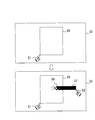
- FIG. 3 is a diagram illustrating an example of the operation screen.
- the operation screen 31 includes a first setting area 32, a drawing area 33, and a second setting area 34.
- the drawing area 33 is an area for performing a drawing operation using the first pointer and the second pointer.
- the first pointer and the second pointer are pointers that can be operated simultaneously and independently, and details will be described later.
- the user performs a drawing operation by touching the drawing area 33 of the operation screen 31 displayed on the touch panel unit 18.
- the first pointer and the second pointer can have different drawing functions.
- a shielding object drawing function can be assigned to the first pointer
- a spray drawing function can be assigned to the second pointer.
- the drawing function assigned to the first pointer is referred to as a first drawing function
- the drawing function assigned to the second pointer is referred to as a second drawing function.
- the first setting area 32 is an area for setting the first drawing function.
- the second setting area 34 is an area for setting the second drawing function.
- the first setting area 32 and the second setting area 34 include sub-areas 32a and 34a for setting a drawing function, respectively.
- any one of a shield, a range specification, and a drawing type can be selected. Since the first pointer is a pointer that is recognized by touching the drawing area 33 before the second pointer, the drawing function that will be operated first, such as a shielding object or range designation, is the first one. It is desirable that selection is possible only in the sub-area 34a for the pointer. Therefore, it is desirable that, for example, any one of the drawing types can be selected in the sub-area 34a for the second pointer. In the example of FIG. 3, the shielding object is selected in the first pointer sub-area 32a, and the spray is selected in the second pointer sub-area 34a.
- sub-areas for making detailed settings related to the selected drawing function are displayed in the empty areas of the first setting area 32 and the second setting area 34, respectively. Is done.
- the sub-area 32b for selecting any one of a plurality of shapes that can be selected as the shield
- the shield And a sub-area 32c for setting the size.
- spray is selected in the sub-area 34a
- the sub-area 34b for selecting one of a plurality of selectable spray spray shapes
- the sub-area 34c for setting the color of the spray
- spray A sub-area 34d for setting the size is displayed.
- range designation is selected as the drawing function, for example, a subarea for selecting an effect (gradation, blurring, mask, etc.) to be applied within the range is displayed.
- the operation determination unit 25 receives input information sent in response to the touch operation of the touch panel unit 18 via the OS 20, and determines a user operation on the touch panel unit 18 based on the received input information. Specifically, when at least one of a touch operation, a release operation, and a drag operation is detected in the touch panel unit 18, the operation determination unit 25 identifies operation information that can identify the operation and a position for specifying the operation position. Input information including information.
- the operation determining unit 25 determines that the operation is in the first setting area 32 or the second setting area 34 of the operation screen 31 based on the input information, the drawing function selected by the user based on the position information. And information about the detailed settings.
- the operation determination unit 25 stores the acquired information in the drawing setting table.
- the drawing setting table is stored in the RAM 12, for example.
- FIG. 4 is a diagram illustrating an example of a drawing setting table.
- the drawing setting table stores, for the first pointer and the second pointer, X and Y coordinates indicating the position of the pointer, a drawing function, detailed settings, and the like.
- position information included in the input information is set.
- the drawing function field of the first pointer the first drawing function selected in the sub area 32a of the first setting area 32 is set.
- information indicating the second drawing function selected in the sub area 34a of the second setting area 34 is set.
- the detailed setting field stores detailed setting information related to the drawing function according to the selected drawing function.
- the detailed setting fields include a first detailed setting field related to shape, a second detailed setting field related to size, a third detailed setting field related to color, and the like.
- a fourth detailed setting field related to effects such as gradation and blurring may be included.
- information selected in each sub area of the first setting area 32 and the second setting area 34 of the operation screen 31 is stored.
- the operation determination unit 25 determines whether or not the input information indicates a first touch in the drawing area 33.
- First touch means a state in which no contact operation other than the contact is performed in the drawing area 33. Therefore, the operation determination unit 25 determines that the touch operation indicated by the input information is the first touch when the touch operation or the drag operation is not performed in the drawing area 33 other than the touch operation indicated by the input information. judge.
- the operation determination unit 25 performs the second touch on the touch operation indicated by the input information. Is determined.
- the operation determination unit 25 When the operation determination unit 25 recognizes the operation of the first pointer, the operation determination unit 25 sets the position information in the X coordinate field and the Y coordinate field of the first pointer in the drawing setting table. When the operation determination unit 25 recognizes the operation of the second pointer, it sets the position information in the X coordinate field and the Y coordinate field of the second pointer in the drawing setting table.
- the operation determination unit 25 displays a first pointer at a position (X coordinate, Y coordinate) where the touch operation determined to be the first touch is performed, and performs a release operation and a drag operation that are transitioned from the touch operation. Recognized as a pointer operation. Specifically, after the first pointer is displayed, when the touch operation transitions to the drag operation, the first pointer moves to the coordinates specified by the position information sequentially input corresponding to the drag operation. Is done. Similarly, the operation determination unit 25 displays the second pointer at the position where the touch operation determined to be the second touch is performed, and the release operation and the drag operation transitioned from the touch operation are regarded as the operation of the second pointer. recognize.
- the operation determination unit 25 deletes the second pointer when the touch operation related to the second pointer is changed to the release operation.
- the operation determination unit 25 deletes each data of the X coordinate field and the Y coordinate field of the second pointer of the drawing setting table.
- the operation determination unit 25 deletes both the first pointer and the second pointer when the touch operation related to the first pointer is changed to the release operation.
- the operation determination unit 25 deletes each data of the X coordinate field and the Y coordinate field of the first pointer of the drawing setting table.
- the operation determination unit 25 When the operation determination unit 25 recognizes the operation of the first pointer, the operation determination unit 25 sends the operation information and information on the first pointer of the drawing setting table to the first generation unit 26. On the other hand, when the operation determination unit 25 recognizes the operation of the second pointer, the operation determination unit 25 sends the operation information and information on the second pointer of the drawing setting table to the second generation unit 27.
- FIG. 5 is a diagram showing a concept of drawing data generation processing by the first generation unit 26, the second generation unit 27, and the drawing data generation unit 28.
- the drawing data generation unit 28 generates drawing data to be finally displayed on the display unit of the touch panel unit 18.
- the drawing data generation unit 28 has a canvas 43 for the drawing data.
- the first generator 26 and the second generator 27 also have their own canvases 41 and 42, respectively.
- the canvases 41, 42, and 43 have the same size, and are stored on the RAM 12 as a memory area corresponding to the size, for example.
- the first generation unit 26 generates first drawing data including an image drawn by a drawing operation using the first pointer on the canvas 41.
- the second generation unit 27 generates second drawing data including an image drawn by a drawing operation using the second pointer on the canvas 42.
- a triangular shielding object is assigned to the first drawing function
- spray drawing is assigned to the second drawing function. Accordingly, drawing data in which the shielding object is drawn at the position pointed to by the first pointer is stored on the canvas 41, and drawing data that is spray-drawn at the position pointed to by the second pointer is stored on the canvas 42. Stored.
- the drawing data generation unit 28 generates drawing data obtained by combining the drawing data on the canvas 41 and the drawing data on the canvas 42 on the canvas 43 (see reference numeral 43 (2) in FIG. 5).
- the drawing data generation unit 28 applies a drawing effect corresponding to the first drawing function or the second drawing function to the drawing portion 46 where the first drawing data and the second drawing data overlap.
- a shielding effect corresponding to the shielding object designated as the first drawing function is applied to the drawing portion 46.
- the blurring effect is applied to the drawing portion 46.
- the drawing data generation unit 28 is newly synthesized with the existing drawing data (reference numeral 43 (1) in FIG. 5).
- Drawing data overwritten with the drawing data (reference numeral 43 (2) in FIG. 5) is generated (reference numeral 43 (3) in FIG. 5).
- the first drawing data is erased with the composition effect remaining. The This is the same when the range designation is designated in the first drawing function.
- the drawing data generation unit 28 displays the drawing data on the display unit of the touch panel unit 18 by sending the drawing data on the canvas 43 to the OS 20. Note that the synthesis of the first drawing data and the second drawing data by the drawing data generation unit 28 may be performed when one of the first drawing data and the second drawing data is updated, It may be executed at a predetermined cycle. Further, the drawing data on the canvas 43 may always be displayed on the display unit of the touch panel unit 18 by the action of the OS 20 or the like.
- FIG. 6 is a flowchart illustrating an operation example of the drawing apparatus 1 according to the first embodiment.
- the touch panel unit 18 sends to the main body unit 10 input information including position information (coordinate information) and operation information corresponding to the contact state regarding the detected contact operation.
- the drawing application 21 is notified of the input information acquisition via the OS 20.
- the operation determination unit 25 acquires this input information.
- the operation determination unit 25 determines a user operation corresponding to the input information (S601). The operation determination unit 25 determines whether the user operation is an operation in the drawing area 33 of the operation screen 31 based on the position information included in the input information (S602). If the operation determination unit 25 determines that the operation is not within the drawing area 33 (S602; NO), the operation determination unit 25 performs general processing according to the operation (S612).
- General operations include operations in the first setting area 32 and the second setting area 34 of the operation screen 31. If the user operation is a setting operation in the first setting area 32, the drawing function corresponding to the setting operation is set in the drawing setting table as the first drawing function. If the user operation is a setting operation in the second setting area 34, the drawing function corresponding to the setting operation is set in the drawing setting table as the second drawing function. In the drawing setting table, initial values may be set as the first drawing function and the second drawing function, respectively.
- the operation determination unit 25 determines whether the user operation is an operation in the drawing area 33 (S602; YES). Specifically, the operation determination unit 25 indicates that the operation information included in the input information indicates a touch operation, and no touch operation or drag operation is performed in the drawing area 33 other than the touch operation at that time. In this case, it is determined that the user operation is a first touch operation.
- the operation determination unit 25 determines that the user operation is the first touch operation (S603; YES)
- the operation determination unit 25 displays the first pointer at the position specified by the position information included in the input information (S604). Subsequently, the operation determination unit 25 sends drawing information related to the first pointer and the operation information thereof to the first generation unit 26.
- the drawing information related to the first pointer includes information (X coordinate and Y coordinate) indicating the position of the first pointer and information related to the drawing function, shape, size, color, etc. designated as the first drawing function.
- the operation determination unit 25 determines whether the user operation is related to the first pointer (S605).
- the user operation related to the first pointer corresponds to a drag operation or a release operation shifted from the first touch state. If the operation determination unit 25 determines that the operation is a user operation related to the first pointer (S605; YES), the operation determination unit 25 sends drawing information related to the first pointer and operation information thereof to the first generation unit 26.
- the first generation unit 26 acquires the drawing information and the operation information related to the first pointer from the operation determination unit 25, the first generation unit 26 generates first drawing data based on the information on the canvas 41 (S606).
- the operation determination unit 25 determines that the user operation is not a first touch operation (S603; NO) and is not a user operation related to the first pointer (S605; NO), does the user operation correspond to a second touch operation? It is determined whether or not (S607). Specifically, in the operation determination unit 25, the operation information included in the input information indicates a touch operation, and at that time, in addition to the touch operation, a touch operation or a drag operation is performed in the drawing area 33. In this case, it is determined that the user operation is a second touch operation. In addition to the touch operation, whether or not a touch operation or a drag operation is performed in the drawing area 33 is determined by, for example, determining whether or not the input information includes a plurality of pieces of operation information. You may implement
- the operation determination unit 25 determines that the user operation is a second touch operation (S607; YES)
- the operation determination unit 25 displays the second pointer at a position specified by the position information included in the input information (S608). Subsequently, the operation determination unit 25 sends drawing information relating to the second pointer and the operation information thereof to the second generation unit 27.
- the drawing information related to the second pointer includes information indicating the position of the second pointer (X coordinate and Y coordinate) and information related to the drawing function, shape, size, color, and the like designated as the second drawing function.
- the operation determining unit 25 determines that the user operation is not a second touch operation (S607; NO)
- the operation determining unit 25 sends drawing information about the second pointer and the operation information to the second generating unit 27.
- the operation determination unit 25 determines that the user operation is not the second touch operation
- the user operation is a user operation related to the second pointer. That is, the user operation corresponds to a drag operation or a release operation using the second pointer transitioned from the second touch.
- the second generation unit 27 acquires the drawing information and the operation information related to the second pointer from the operation determination unit 25, the second generation unit 27 generates second drawing data based on the information on the canvas 42 (S609).
- the drawing data generation unit 28 generates combined drawing data obtained by combining the first drawing data generated by the first generation unit 26 and the second drawing data generated by the second generation unit 27 (S610).
- the drawing data generation unit 28 gives a drawing effect corresponding to the first drawing function or the second drawing function to a drawing portion where the first drawing data and the second drawing data overlap in the creation of the composite drawing data.
- the composite drawing data generated by the drawing data generation unit 28 is sent to the touch panel unit 18 via the OS 20 and the UI controller 14. As a result, a screen corresponding to the combined drawing data is displayed on the display unit of the touch panel unit 18 (S611).
- FIG. 7 is a diagram illustrating a drawing example 1 performed by the drawing apparatus according to the first embodiment.
- the figure 55 is already drawn in the drawing area 33 of the operation screen 31.
- the user selects range designation as the first drawing function in the sub-area 32a of the first setting area 32 of the operation screen 31.
- a range-designated drawing function is selected in the sub-area 32a
- a range-designated shape selection screen is displayed in the sub-area 32b
- an effect selection screen within the range is displayed in the sub-area 32c.
- a square is selected as the shape for specifying the range
- blurring is selected as the effect within the range.
- the user selects a pen in the drawing type as the second drawing function in the sub-area 34a of the second setting area 34 of the operation screen 31.
- a pen thickness selection screen is displayed in the sub area 34b, and a pen color selection screen is displayed in the sub area 34c.
- a predetermined thickness is selected, and a predetermined color is selected.
- the touch panel operation may be performed using an article such as a touch pen.
- the user touches the drawing area 33 of the operation screen 31 displayed on the touch panel unit 18 with the finger of one arm. This operation is determined as a first touch operation in the drawing apparatus 1, and the first pointer 51 is displayed on the touch panel unit 18. Thereafter, the first pointer 51 moves following the movement of the touched finger.
- the user designates the range 56 by sliding the touched finger (first pointer 51).
- the range designation and the detailed setting designated as the first drawing function are reflected.
- the first generation unit 26 in the drawing apparatus 1 draws an image indicating the designated range 56 on its own campus 41.
- the user touches the finger on the touch panel as it is and touches the finger on the other arm to a predetermined position indicating the inside of the drawing area 33 of the operation screen 31 on the touch panel.
- This operation is determined as a second touch operation in the drawing apparatus 1, and the second pointer 52 is displayed on the touch panel unit 18. Thereafter, the second pointer 52 moves following the movement of the finger that has performed the second touch operation.
- the user performs drawing using the pen by sliding the finger (second pointer 52) that has performed the second touch operation.
- the pen drawing 57 drawn by the pen drawing reflects the pen drawing function designated as the second drawing function and its detailed settings.
- the second generation unit 27 in the drawing apparatus 1 draws the pen image 57 on its own campus 42.
- the drawing data generation unit 28 generates combined drawing data of the range 56 drawn by the first pointer 51 and the pen drawing 57 drawn by the second pointer 52, and displays the combined drawing data on the touch panel unit 18. At this time, as shown in the example of FIG. 7, a part of the pen image 57 is included in the range 56.
- the drawing data generation unit 28 imparts a blurring effect as a range designation attribute to the portion 58 of the pen drawing 57 included in the range 56 drawn by the first pointer 51.
- the second pointer 52 is erased and the pen image 57 is determined.
- the first pointer 51 is erased and the image indicating the range 56 disappears.
- FIG. 8 is a diagram illustrating a drawing example 2 using the drawing apparatus according to the first embodiment.
- the range designation is selected as the first drawing function
- the square is selected as the shape of the range designation
- the gradation is selected as the effect within the range.
- a pen is designated as the second drawing function, and a predetermined thickness and a predetermined color are selected.
- a gradation effect as a range designation attribute is applied to the portion 59 of the pen image 57 included in the range 56 drawn by the first pointer 51.
- FIG. 9 is a diagram illustrating a drawing example 3 using the drawing apparatus according to the first embodiment.
- FIG. 9 shows an example in which drawing types are selected for the first drawing function and the second drawing function, respectively. Specifically, the pen is selected as the first drawing function, and the spray is selected as the second drawing function.
- the pen image 61 is created using the first pointer 51, and the spray image 62 is created using the second pointer 52.
- the pen image 61 is prioritized for the portion where the pen image 61 and the spray image 62 overlap. As a result, the pen image 61 is overwritten on the spray image 62.
- the drawing apparatus 1 in the first embodiment the first pointer and the second pointer are displayed simultaneously in response to a plurality of contact operations performed independently on the touch panel unit 18.
- Different drawing functions can be designated as the first drawing function and the second drawing function for the first pointer and the second pointer, respectively, and information regarding each drawing function is stored in the drawing setting table.
- each drawing data corresponding to the first drawing function and the second drawing function is generated by the drawing operation in the drawing area 33 using the first pointer and the second pointer, and these drawing data are synthesized.
- the composite drawing data is displayed on the touch panel unit 18.
- the user who uses the drawing apparatus 1 according to the first embodiment can draw by the same operation as when actually drawing with both hands. Therefore, spray art using a pattern with one hand and spraying with the other hand can also be realized by an easy operation. According to the first embodiment, since drawing using both hands is possible, the operability of drawing is improved as compared with the prior art.
- drawing functions can be set for the first pointer and the second pointer, drawing functions according to various user requests can be provided.
- FIG. 10 is a diagram showing an example of a drawing setting table in the modification.
- a priority field may be added to the drawing setting table to store priorities related to the first drawing function and the second drawing function.
- priority information selected in each of the sub-areas of the first setting area 32 and the second setting area 34 of the operation screen 31 is stored.
- the drawing data generation unit 28 designates drawing types as the first drawing function and the second drawing function
- priority is given based on the priority information stored in the drawing setting table.
- a high-level drawing function may be preferentially applied.
- the priority application is, for example, overwriting.
- the drawing device 1 in the above-described first embodiment includes the touch panel unit 18, and a user operation is performed using the touch panel unit 18.
- the drawing apparatus 1 may include user operation input means other than the touch panel unit 18.
- FIG. 10 is a diagram illustrating a hardware configuration example of a drawing apparatus according to a modification.
- An example of the above-described user operation input means is a mouse.
- the touch panel unit 18 and the mouse 71 may be connected to the UI controller 14, or at least two mice 71 may be connected instead of the touch panel unit 18.
- the operation determination unit 25 in the modification may not determine the first touch operation and the second touch operation.
- the first generator 26 generates an image drawn with the mouse 71 (1) corresponding to the first pointer
- the second generator 27 generates an image drawn with the mouse 71 (2) corresponding to the second pointer. You just have to do it.
- the pointer corresponding to the mouse 71 is displayed by the OS 20.
- the operation determination unit 25 in the modification example has the mouse 71.
- the pointer corresponding to may be determined as the first pointer. In this case, when an operation in the drawing area 33 using the touch panel is performed in a state where the pointer corresponding to the mouse 71 is displayed in the drawing area 33, the contact operation is determined as the second touch operation.
- the contact operation is determined as the first operation. Except for the determination processing of the first pointer and the second pointer, it may be the same as in the first embodiment.
- a hardware component is a hardware circuit, for example, a field programmable gate array (FPGA), an application specific integrated circuit (ASIC), a gate array, a combination of logic gates, a signal processing circuit, an analog circuit, etc. There is.
- FPGA field programmable gate array
- ASIC application specific integrated circuit
- Software components are parts (fragments) that realize the above processing as software, and are not a concept that limits the language, development environment, etc. that realizes the software.
- Examples of software components include tasks, processes, threads, drivers, firmware, databases, tables, functions, procedures, subroutines, predetermined portions of program code, data structures, arrays, variables, parameters, and the like.
- These software components are realized on one or a plurality of memories (for example, one or a plurality of processors (for example, CPU (Central Processing Unit), DSP (Digital Signal Processing), etc.)).
- Each processing unit may be configured as a hardware component, a software component, or a combination thereof by a method that can be realized by a normal engineer in this technical field.
Landscapes
- Engineering & Computer Science (AREA)
- Theoretical Computer Science (AREA)
- General Engineering & Computer Science (AREA)
- Physics & Mathematics (AREA)
- General Physics & Mathematics (AREA)
- Human Computer Interaction (AREA)
- User Interface Of Digital Computer (AREA)
- Processing Or Creating Images (AREA)
Abstract
L'invention porte sur un dispositif de dessin qui comporte un moyen de commande de pointeurs pour détecter des opérations à l'aide d'un premier pointeur et d'un second pointeur, respectivement, dans une zone de dessin, un premier moyen de génération pour générer des premières données de dessin conformément à une première fonction de dessin spécifiée pour le premier pointeur et l'opération à l'aide du premier pointeur dans la zone de dessin, un second moyen de génération pour générer des secondes données de dessin conformément à une seconde fonction de dessin spécifiée pour le second pointeur et l'opération à l'aide du second pointeur dans la zone de dessin, et un moyen de dessin pour générer les données de dessin qui fournissent l'effet de dessin correspondant à la première fonction de dessin ou à la seconde fonction de dessin sur la partie de dessin dans laquelle les premières données de dessin et les secondes données de dessin se chevauchent entre elles, permettant ainsi d'améliorer l'exploitabilité du dessin.
Priority Applications (3)
| Application Number | Priority Date | Filing Date | Title |
|---|---|---|---|
| PCT/JP2009/061917 WO2011001504A1 (fr) | 2009-06-30 | 2009-06-30 | Dispositif de dessin et procédé de dessin |
| JP2011520696A JP5338908B2 (ja) | 2009-06-30 | 2009-06-30 | 描画装置及び描画方法 |
| US13/341,371 US20120105322A1 (en) | 2009-06-30 | 2011-12-30 | Drawing device and drawing method |
Applications Claiming Priority (1)
| Application Number | Priority Date | Filing Date | Title |
|---|---|---|---|
| PCT/JP2009/061917 WO2011001504A1 (fr) | 2009-06-30 | 2009-06-30 | Dispositif de dessin et procédé de dessin |
Related Child Applications (1)
| Application Number | Title | Priority Date | Filing Date |
|---|---|---|---|
| US13/341,371 Continuation US20120105322A1 (en) | 2009-06-30 | 2011-12-30 | Drawing device and drawing method |
Publications (1)
| Publication Number | Publication Date |
|---|---|
| WO2011001504A1 true WO2011001504A1 (fr) | 2011-01-06 |
Family
ID=43410602
Family Applications (1)
| Application Number | Title | Priority Date | Filing Date |
|---|---|---|---|
| PCT/JP2009/061917 WO2011001504A1 (fr) | 2009-06-30 | 2009-06-30 | Dispositif de dessin et procédé de dessin |
Country Status (3)
| Country | Link |
|---|---|
| US (1) | US20120105322A1 (fr) |
| JP (1) | JP5338908B2 (fr) |
| WO (1) | WO2011001504A1 (fr) |
Cited By (5)
| Publication number | Priority date | Publication date | Assignee | Title |
|---|---|---|---|---|
| WO2013158938A1 (fr) | 2012-04-18 | 2013-10-24 | Solazyme, Inc. | Huiles formulées sur mesure |
| WO2014176515A2 (fr) | 2013-04-26 | 2014-10-30 | Solazyme, Inc. | Huiles à teneur faible en acides gras polyinsaturés et leurs utilisations |
| WO2015051319A2 (fr) | 2013-10-04 | 2015-04-09 | Solazyme, Inc. | Huiles sur mesure huiles sur mesure |
| WO2016007862A2 (fr) | 2014-07-10 | 2016-01-14 | Solazyme, Inc. | Nouveaux gènes de la cétoacyl-acp-synthase et leurs utilisations |
| WO2016164495A1 (fr) | 2015-04-06 | 2016-10-13 | Solazyme, Inc. | Micro-algues oléagineuses présentant une ablation lpaat |
Families Citing this family (4)
| Publication number | Priority date | Publication date | Assignee | Title |
|---|---|---|---|---|
| KR20130130453A (ko) * | 2012-05-22 | 2013-12-02 | 엘지전자 주식회사 | 영상표시장치 및 그 동작 방법 |
| GB201212521D0 (en) * | 2012-07-13 | 2012-08-29 | Wapple Net Ltd | Drawing package |
| CN103207730B (zh) * | 2013-04-03 | 2016-03-09 | 广东飞企互联科技股份有限公司 | 一种可定位拖拉式流程图生成方法及流程图生成器 |
| KR102314110B1 (ko) * | 2014-09-16 | 2021-10-18 | 삼성디스플레이 주식회사 | 시각화 가속부를 포함하는 터치 표시 장치 |
Citations (2)
| Publication number | Priority date | Publication date | Assignee | Title |
|---|---|---|---|---|
| JP2003158713A (ja) * | 2001-11-21 | 2003-05-30 | Omron Corp | 画像印刷装置および方法、印刷媒体ユニット、並びにプログラム |
| JP2005341558A (ja) * | 2005-04-28 | 2005-12-08 | Omron Entertainment Kk | 編集機能付き写真撮影装置 |
Family Cites Families (5)
| Publication number | Priority date | Publication date | Assignee | Title |
|---|---|---|---|---|
| JP3429618B2 (ja) * | 1995-11-24 | 2003-07-22 | 大日本スクリーン製造株式会社 | 画像部品の切抜き機能を有する画像レイアウト装置 |
| US20030006961A1 (en) * | 2001-07-09 | 2003-01-09 | Yuly Shipilevsky | Method and system for increasing computer operator's productivity |
| JP2004355191A (ja) * | 2003-05-28 | 2004-12-16 | Nippon Telegr & Teleph Corp <Ntt> | 情報整理システム、このシステム用のアプリケーションプログラム、およびこのシステム用のドライバ |
| US8089457B2 (en) * | 2006-05-19 | 2012-01-03 | Panasonic Corporation | Image operating device, image operating method, and image operating program embodied on computer readable medium |
| GB2456247B (en) * | 2006-10-10 | 2009-12-09 | Promethean Ltd | Interactive display system with master/slave pointing devices |
-
2009
- 2009-06-30 JP JP2011520696A patent/JP5338908B2/ja not_active Expired - Fee Related
- 2009-06-30 WO PCT/JP2009/061917 patent/WO2011001504A1/fr active Application Filing
-
2011
- 2011-12-30 US US13/341,371 patent/US20120105322A1/en not_active Abandoned
Patent Citations (2)
| Publication number | Priority date | Publication date | Assignee | Title |
|---|---|---|---|---|
| JP2003158713A (ja) * | 2001-11-21 | 2003-05-30 | Omron Corp | 画像印刷装置および方法、印刷媒体ユニット、並びにプログラム |
| JP2005341558A (ja) * | 2005-04-28 | 2005-12-08 | Omron Entertainment Kk | 編集機能付き写真撮影装置 |
Cited By (5)
| Publication number | Priority date | Publication date | Assignee | Title |
|---|---|---|---|---|
| WO2013158938A1 (fr) | 2012-04-18 | 2013-10-24 | Solazyme, Inc. | Huiles formulées sur mesure |
| WO2014176515A2 (fr) | 2013-04-26 | 2014-10-30 | Solazyme, Inc. | Huiles à teneur faible en acides gras polyinsaturés et leurs utilisations |
| WO2015051319A2 (fr) | 2013-10-04 | 2015-04-09 | Solazyme, Inc. | Huiles sur mesure huiles sur mesure |
| WO2016007862A2 (fr) | 2014-07-10 | 2016-01-14 | Solazyme, Inc. | Nouveaux gènes de la cétoacyl-acp-synthase et leurs utilisations |
| WO2016164495A1 (fr) | 2015-04-06 | 2016-10-13 | Solazyme, Inc. | Micro-algues oléagineuses présentant une ablation lpaat |
Also Published As
| Publication number | Publication date |
|---|---|
| US20120105322A1 (en) | 2012-05-03 |
| JPWO2011001504A1 (ja) | 2012-12-10 |
| JP5338908B2 (ja) | 2013-11-13 |
Similar Documents
| Publication | Publication Date | Title |
|---|---|---|
| JP5338908B2 (ja) | 描画装置及び描画方法 | |
| US9223471B2 (en) | Touch screen control | |
| US7640518B2 (en) | Method and system for switching between absolute and relative pointing with direct input devices | |
| US20080109763A1 (en) | Computer system and method thereof | |
| WO2010032354A1 (fr) | Système de commande d'un objet image, procédé de commande d'un objet image, et programme | |
| US20130063384A1 (en) | Electronic apparatus, display method, and program | |
| US20090091547A1 (en) | Information display device | |
| JP3982288B2 (ja) | 三次元ウィンドウ表示装置、三次元ウィンドウ表示方法及び三次元ウィンドウ表示プログラム | |
| JP2010055627A (ja) | 3次元ポインティング方法、3次元表示制御方法、3次元ポインティング装置、3次元表示制御装置、3次元ポインティングプログラム、及び3次元表示制御プログラム | |
| JP5848732B2 (ja) | 情報処理装置 | |
| CN101308428B (zh) | 将图形输入板映射到显示器的设备、方法和计算机可读介质 | |
| JP2011128962A (ja) | 画像処理装置、画像処理方法、及びコンピュータプログラム | |
| US8839156B2 (en) | Pointer tool for touch screens | |
| JP4106058B2 (ja) | ウィンドウ内におけるフレーム再配置を行うための情報処理装置、フレームの再配置方法、およびプログラム | |
| CN107924268B (zh) | 对象选择系统和方法 | |
| JP6613338B2 (ja) | 情報処理装置、情報処理プログラムおよび情報処理方法 | |
| JP5813927B2 (ja) | 画像作成編集ツールのプレビュー方法およびプログラム | |
| JP6352801B2 (ja) | 情報処理装置、情報処理プログラムおよび情報処理方法 | |
| US9417780B2 (en) | Information processing apparatus | |
| JP5618926B2 (ja) | マルチポインティングデバイスの制御方法及びプログラム | |
| JP4925989B2 (ja) | 入力装置及びコンピュータプログラム | |
| JP2020061179A (ja) | 情報処理装置、情報処理方法および情報処理プログラム | |
| JP6698780B2 (ja) | 情報処理装置及びポインタ表示制御方法並びにプログラム | |
| JP2004118752A (ja) | タッチパネル付きディスプレイ装置、上書き制御方法、その方法をコンピュータに実行させるプログラム、そのプログラムを記録したコンピュータ読み取り可能な記録媒体 | |
| JP2020106959A (ja) | レイアウト処理装置 |
Legal Events
| Date | Code | Title | Description |
|---|---|---|---|
| 121 | Ep: the epo has been informed by wipo that ep was designated in this application |
Ref document number: 09846797 Country of ref document: EP Kind code of ref document: A1 |
|
| WWE | Wipo information: entry into national phase |
Ref document number: 2011520696 Country of ref document: JP |
|
| NENP | Non-entry into the national phase |
Ref country code: DE |
|
| 122 | Ep: pct application non-entry in european phase |
Ref document number: 09846797 Country of ref document: EP Kind code of ref document: A1 |