WO2010150895A1 - 無線基地局及び補正値算出方法 - Google Patents
無線基地局及び補正値算出方法 Download PDFInfo
- Publication number
- WO2010150895A1 WO2010150895A1 PCT/JP2010/060907 JP2010060907W WO2010150895A1 WO 2010150895 A1 WO2010150895 A1 WO 2010150895A1 JP 2010060907 W JP2010060907 W JP 2010060907W WO 2010150895 A1 WO2010150895 A1 WO 2010150895A1
- Authority
- WO
- WIPO (PCT)
- Prior art keywords
- value
- mcs
- correction value
- sinr
- base station
- Prior art date
- Legal status (The legal status is an assumption and is not a legal conclusion. Google has not performed a legal analysis and makes no representation as to the accuracy of the status listed.)
- Ceased
Links
Images




Classifications
-
- H—ELECTRICITY
- H04—ELECTRIC COMMUNICATION TECHNIQUE
- H04L—TRANSMISSION OF DIGITAL INFORMATION, e.g. TELEGRAPHIC COMMUNICATION
- H04L1/00—Arrangements for detecting or preventing errors in the information received
- H04L1/0001—Systems modifying transmission characteristics according to link quality, e.g. power backoff
- H04L1/0015—Systems modifying transmission characteristics according to link quality, e.g. power backoff characterised by the adaptation strategy
-
- H—ELECTRICITY
- H04—ELECTRIC COMMUNICATION TECHNIQUE
- H04B—TRANSMISSION
- H04B17/00—Monitoring; Testing
- H04B17/20—Monitoring; Testing of receivers
- H04B17/21—Monitoring; Testing of receivers for calibration; for correcting measurements
-
- H—ELECTRICITY
- H04—ELECTRIC COMMUNICATION TECHNIQUE
- H04B—TRANSMISSION
- H04B17/00—Monitoring; Testing
- H04B17/30—Monitoring; Testing of propagation channels
- H04B17/309—Measuring or estimating channel quality parameters
-
- H—ELECTRICITY
- H04—ELECTRIC COMMUNICATION TECHNIQUE
- H04L—TRANSMISSION OF DIGITAL INFORMATION, e.g. TELEGRAPHIC COMMUNICATION
- H04L1/00—Arrangements for detecting or preventing errors in the information received
- H04L1/0001—Systems modifying transmission characteristics according to link quality, e.g. power backoff
- H04L1/0002—Systems modifying transmission characteristics according to link quality, e.g. power backoff by adapting the transmission rate
- H04L1/0003—Systems modifying transmission characteristics according to link quality, e.g. power backoff by adapting the transmission rate by switching between different modulation schemes
-
- H—ELECTRICITY
- H04—ELECTRIC COMMUNICATION TECHNIQUE
- H04L—TRANSMISSION OF DIGITAL INFORMATION, e.g. TELEGRAPHIC COMMUNICATION
- H04L1/00—Arrangements for detecting or preventing errors in the information received
- H04L1/0001—Systems modifying transmission characteristics according to link quality, e.g. power backoff
- H04L1/0009—Systems modifying transmission characteristics according to link quality, e.g. power backoff by adapting the channel coding
-
- H—ELECTRICITY
- H04—ELECTRIC COMMUNICATION TECHNIQUE
- H04L—TRANSMISSION OF DIGITAL INFORMATION, e.g. TELEGRAPHIC COMMUNICATION
- H04L1/00—Arrangements for detecting or preventing errors in the information received
- H04L1/20—Arrangements for detecting or preventing errors in the information received using signal quality detector
-
- H—ELECTRICITY
- H04—ELECTRIC COMMUNICATION TECHNIQUE
- H04L—TRANSMISSION OF DIGITAL INFORMATION, e.g. TELEGRAPHIC COMMUNICATION
- H04L1/00—Arrangements for detecting or preventing errors in the information received
- H04L1/0001—Systems modifying transmission characteristics according to link quality, e.g. power backoff
- H04L1/0023—Systems modifying transmission characteristics according to link quality, e.g. power backoff characterised by the signalling
- H04L1/0026—Transmission of channel quality indication
-
- H—ELECTRICITY
- H04—ELECTRIC COMMUNICATION TECHNIQUE
- H04W—WIRELESS COMMUNICATION NETWORKS
- H04W88/00—Devices specially adapted for wireless communication networks, e.g. terminals, base stations or access point devices
- H04W88/08—Access point devices
Definitions
- the present invention is used when determining a radio base station that determines MCS (Modulation and Coding scheme) corresponding to the communication quality of the radio resource, and an MCS corresponding to the communication quality of the radio resource in the radio base station.
- the present invention relates to a correction value calculation method in a correction value calculation device for calculating a communication quality correction value.
- OFDMA Orthogonal Frequency Division Multiple Access
- a radio base station manages a large number of radio terminals, and in order to effectively use radio resources, scheduling in which radio resources divided in a time direction and a frequency direction are allocated to radio terminals is 2 A dimension scheduler is used.
- the radio base station can allocate radio resources of different frequencies to the radio terminals in the scheduling in the time direction. Thereby, efficient transmission is possible in response to time changes and frequency changes in the wireless environment.
- the radio base station needs to know the communication quality with the radio terminal.
- the radio base station can recognize the communication quality in the downlink direction by CQI (Channel Quality Indicator) from the radio terminal.
- CQI Channel Quality Indicator
- CQI corresponds to MCS (Modulation and Coding Scheme) that is uniquely determined by the modulation scheme and transfer block size.
- MCS Modulation and Coding Scheme
- FER Fre Error Rate
- SINR Signal ⁇ toQInterference and Noise power Ratio
- SINR that satisfies the condition that FER is 10% in a predetermined MCS can be calculated in advance by computer simulation or the like. This calculated value can be used as a threshold when the radio base station selects the MCS of the downlink radio resource based on the SINR corresponding to the CQI from the radio terminal.
- S-CQI Subscribeband CQI
- E-SINR Effective SINR
- the E-SINR is a value obtained by synthesizing SINR corresponding to the S-CQI of each subband allocated to the wireless terminal.
- EESM Extra Effective SIR Mapping
- the MCS that satisfies the condition that the FER is 10% is determined by comparing the E-SINR with the threshold value of the E-SINR that satisfies the condition that the FER is 10%.
- the radio resource allocation interval in the time direction is 1 [msec], which is the time of one subframe. Therefore, the radio base station must complete the allocation of one subframe within 1 [msec].
- Proportional Fair a scheduling method used to ensure fairness between wireless terminals. Also in Proportional Fair, scheduling in the time direction and the frequency direction is performed, so that the processing amount in the radio base station increases compared to the Round Robin method, which is a scheduling method only in the time direction before that. Also, when considering QoS and the like, the scheduler becomes more sophisticated, and the processing amount in the radio base station further increases.
- the present invention provides a radio base station and a correction value calculation method capable of determining an appropriate MCS according to communication quality while reducing the processing amount in the radio base station. With the goal.
- the first feature of the present invention is a radio base station that determines MCS (Modulation and Coding Scheme) corresponding to the communication quality of a radio resource, and the communication quality of the radio resource used for communication with a radio terminal.
- the gist is to include a correction unit (MCS determination unit 164) that acquires communication quality and an MCS determination unit (MCS determination unit 164) that determines an MCS corresponding to the corrected communication quality.
- Such a radio base station selects an MCS corresponding to the communication quality of the radio resource used for communication with the radio terminal. Next, the radio base station acquires a correction value corresponding to the selected MCS, and adds the acquired correction value to the communication quality of the radio resource to obtain the corrected communication quality. Therefore, even if the wireless base station acquires the communication quality by conversion using a table in order to reduce the processing amount, even if the accuracy of the communication quality is reduced, the corrected communication quality And the threshold value can be compared to determine an appropriate MCS according to the communication quality.
- the second feature of the present invention relates to the first feature of the present invention, wherein the correspondence between the MCS and the ideal value of the threshold value of communication quality, the correspondence between the MCS and the correction value is shown.
- a correction value table indicating a relationship, wherein the correction value acquisition unit selects an MCS corresponding to the communication quality of the radio resource based on the threshold value table, and selects the selected MCS based on the correction value table. The correction value corresponding to is calculated, and the MCS determination unit determines the MCS corresponding to the corrected communication quality based on the threshold value table.
- a third feature of the present invention relates to the first or second feature of the present invention, and is a first feature obtained by an operation using a first value indicating communication quality and a first function for the first value.
- a first table indicating a correspondence relationship with a value of 2, a third value indicating communication quality, and a second function which is an inverse operation of an operation using the first function for the third value.
- a first conversion unit (exponential index) that converts the ideal value of the threshold value into a first calculation value by using the second table indicating the correspondence relationship with the fourth value obtained by the calculation used, and the first table.
- Function conversion unit 212 Function conversion unit 212
- second conversion unit logarithmic function conversion unit 2114 that converts the first calculation value into a corrected threshold value using the second table, an ideal value of the threshold value
- a correction value calculation unit correction value calculation unit 2166 that calculates the difference from the corrected threshold value as the correction value.
- the fourth feature of the present invention relates to the third feature of the present invention, and is summarized in that the first function is an exponential function and the second function is a logarithmic function.
- the fifth feature of the present invention is that the correction in the correction value calculation device for calculating the correction value of the communication quality used when determining the MCS (Modulation and Coding Scheme) corresponding to the communication quality of the radio resource in the radio base station.
- the correction value calculation device (exponential function conversion unit 212) obtains a second value obtained by a calculation using a first value indicating communication quality and a first function for the first value.
- the step of converting the calculated value into a corrected threshold value, and the correction value calculation device calculates the difference between the ideal value of the threshold value and the corrected threshold value as the correction value. And a step.
- the present invention it is possible to determine an appropriate MCS according to the communication quality while reducing the processing amount in the radio base station.
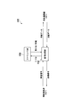
- FIG. 1 is a diagram showing an overall schematic configuration of a radio communication system according to an embodiment of the present invention.
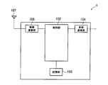
- FIG. 2 is a diagram illustrating a configuration of a radio base station according to the embodiment of the present invention.
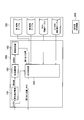
- FIG. 3 is a diagram illustrating a configuration of a control unit according to the embodiment of the present invention.
- FIG. 4 is a diagram showing a configuration of the scheduler unit according to the embodiment of the present invention.
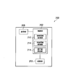
- FIG. 5 is a diagram showing the configuration of the correction value calculation apparatus according to the embodiment of the present invention.
- FIG. 6 is a diagram showing an example of the MCS threshold value table showing the correspondence between the MCS and the SINR threshold value according to the embodiment of the present invention.
- FIG. 1 is a diagram showing an overall schematic configuration of a radio communication system according to an embodiment of the present invention.
- FIG. 2 is a diagram illustrating a configuration of a radio base station according to the embodiment of the present invention.
- FIG. 3 is a diagram illustrating a configuration of a
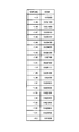
- FIG. 7 is a diagram showing an example of a first conversion table showing the correspondence between SINR and EESM according to the embodiment of the present invention.
- FIG. 8 is a diagram showing an example of the second conversion table showing the correspondence between the EESM ⁇ and the E-SINR according to the embodiment of the present invention.
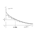
- FIG. 9 is a diagram showing an error when the first conversion table according to the embodiment of the present invention is used.
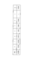
- FIG. 10 is a diagram showing an example of an E-SINR correction value table showing the correspondence between MCS and correction values according to the embodiment of the present invention.
- FIG. 11 is a flowchart showing an operation of the radio base station according to the embodiment of the present invention.
- FIG. 1 is a diagram showing an overall schematic configuration of a radio communication system 10 according to an embodiment of the present invention.
- the wireless communication system 10 shown in FIG. 1 has a configuration based on LTE (Long Term Evolution), which is a standard formulated by 3GPP.
- the wireless communication system 10 includes a wireless base station 1, a wireless terminal 2 ⁇ / b> A and a wireless terminal 2 ⁇ / b> B, and a correction value calculation device 200.
- the radio terminal 2 ⁇ / b> A and the radio terminal 2 ⁇ / b> B exist in a cell 3 provided by the radio base station 1.
- the radio base station 1 has one or a plurality of radio resources as radio resources in the downlink direction (the direction from the radio base station 1 to the radio terminals 2A and 2B) with respect to the radio terminals 2A and 2B existing in the cell 3.
- FIG. 2 is a diagram illustrating a configuration of the radio base station 1.
- the radio base station 1 illustrated in FIG. 2 includes a control unit 102, a storage unit 103, a wired communication unit 104, a radio communication unit 105, and an antenna 107.
- the control unit 102 is constituted by a CPU, for example, and controls various functions provided in the radio base station 1.
- the storage unit 103 is configured by a memory, for example, and stores various types of information used for control and the like in the radio base station 1.
- the wired communication unit 104 is connected to an access gateway or the like existing in the upper network via a router or the like (not shown).
- the radio communication unit 105 receives radio signals from the radio terminals 2A and 2B via the antenna 107 and transmits radio signals to the radio terminals 2A and 2B.
- FIG. 3 is a diagram illustrating a configuration of the control unit 102. As shown in FIG. 3, the control unit 102 includes a signal processing unit 152 and a scheduler unit 154.
- the signal processing unit 152 inputs data (transmission data) transmitted from the host network via the wired communication unit 104. Further, the signal processing unit 152 performs encoding and modulation on the transmission data to generate a transmission signal. Further, the signal processing unit 152 transmits a transmission signal to the wireless terminal 2A and the wireless terminal 2B via the wireless communication unit 105 and the antenna 107.
- the signal processing unit 152 inputs a signal (received signal) transmitted from the wireless terminal 2A and the wireless terminal 2B via the antenna 107 and the wireless communication unit 105. Further, the signal processing unit 152 demodulates and decodes the received signal to generate data (received data). Further, the signal processing unit 152 transmits the received data to the upper network via the wired communication unit 104.
- the radio base station 1 allocates a subband, which is a radio resource in the downlink direction (direction from the radio base station 1 to the radio terminal 2A and the radio terminal 2B), to the radio terminal 2A and the radio terminal 2B, and performs communication.
- a subband which is a radio resource in the downlink direction (direction from the radio base station 1 to the radio terminal 2A and the radio terminal 2B), to the radio terminal 2A and the radio terminal 2B, and performs communication.
- the MCS of the subband is determined. In this case, the following processing is performed.
- the wireless terminal 2A and the wireless terminal 2B transmit a wireless signal including S-CQI indicating the communication quality of the subband.
- the signal processing unit 152 extracts an S-CQI indicating subband communication quality included in the received data.
- the S-CQI includes identification information of a corresponding subband and a terminal ID that is identification information of the transmission source wireless terminal 2. Further, the signal processing unit 152 outputs the extracted S-CQI to the scheduler unit 154.
- FIG. 4 is a diagram showing a configuration of the scheduler unit 154. As shown in FIG. 4 includes a priority calculation unit 161, a terminal selection unit 162, an assignment determination unit 163, and an MCS determination unit 164.
- the priority calculation unit 161 inputs the S-CQI from the signal processing unit 152. Furthermore, the priority calculation unit 161 calculates the priority of subband allocation to the wireless terminal that is the source of S-CQI at a predetermined timing. For example, the storage unit 103 stores, for each wireless terminal, the number of subbands assigned to the wireless terminal. When the priority calculating unit 161 receives the S-CQI from the wireless terminal 2A and the wireless terminal 2B, the priority calculating unit 161 has the smaller number of allocated subbands based on the number of allocated subbands stored in the storage unit 103. The priority of subband allocation to the wireless terminal is increased, and the priority of subband allocation to the radio terminal with the larger number of allocated subbands is decreased.
- the priority calculation unit 161 outputs the subband assignment priority calculated for each wireless terminal to the terminal selection unit 162 together with the terminal ID of the wireless terminal.
- the terminal selection unit 162 inputs a subband allocation priority and a terminal ID for each wireless terminal. Next, terminal selection section 162 selects a radio terminal to which a subband is to be assigned next at a predetermined timing based on the priority of subband assignment corresponding to each radio terminal. Further, the terminal selection unit 162 outputs the selected terminal ID of the wireless terminal to which a subband is to be allocated next to the allocation determination unit 163.
- the assignment determining unit 163 inputs the terminal ID of the wireless terminal to which the subband is to be assigned next. Next, the allocation determination unit 163 determines a subband to be allocated to the wireless terminal corresponding to the input terminal ID. For example, the storage unit 103 stores, for each subband, allocation status information including identification information of the subband and an allocation status indicating whether or not the subband has been allocated. The allocation determining unit 163 selects an unallocated subband based on the allocation status information. Furthermore, the allocation determination unit 163 uses the MCS determination unit together with the identification information of a plurality of unassigned subbands as information (assignment positions) of the plurality of subbands to be assigned to the wireless terminal, together with the terminal ID of the wireless terminal. To 164.
- the MCS determination unit 164 receives the S-CQI from the signal processing unit 152. In addition, the MCS determination unit 164 receives a plurality of allocation positions and terminal IDs from the allocation determination unit 163. Next, the MCS determination unit 164 includes an S-CQI from the signal processing unit 152, a plurality of allocation positions and terminal IDs from the allocation determination unit 163, and a first conversion table described later stored in the storage unit 103, Based on the second conversion table, the MCS threshold value table, and the E-SINR correction value table, the MCSs of a plurality of subbands to be assigned to the wireless terminal corresponding to the terminal ID are determined. A specific MCS determination method will be described later.
- the E-SINR correction value table is generated by the correction value calculation apparatus 200.
- FIG. 5 is a diagram showing a configuration of the correction value calculation apparatus 200.
- a correction value calculation apparatus 200 illustrated in FIG. 5 includes a control unit 202, a storage unit 203, and a communication unit 205.
- the control unit 202 is configured by a CPU, for example, and controls various functions provided in the radio base station 1.
- the storage unit 203 includes, for example, a memory, and stores various types of information used for control and the like in the correction value calculation apparatus 200.
- the communication unit 205 is connected to the radio base station 1.
- the control unit 202 includes an exponential function conversion unit 212, a logarithmic function conversion unit 214, and a correction value calculation unit 216.
- the exponential function conversion unit 212, the logarithmic function conversion unit 214, and the correction value calculation unit 216 use the various tables stored in the storage unit 203 to generate an E-SINR correction value table.
- the MCS threshold value table shown in FIG. 6, the first conversion table shown in FIG. 7, and the second conversion table shown in FIG. 8 are stored in the storage unit 203.
- the MCS threshold table shown in FIG. 6 shows a correspondence relationship between MCS and an ideal E-SINR threshold that is an ideal value of the lower limit of E-SINR that satisfies the condition that FER is 10%.
- the exponential function conversion unit 212 acquires an ideal E-SINR threshold corresponding to each MCS based on the MCS threshold table shown in FIG. For example, the exponential function conversion unit 212 acquires ⁇ 1.42152 as the ideal E-SINR threshold corresponding to MCS4.
- the exponential function conversion unit 212 uses each ideal E-SINR threshold value as SINR, and acquires an EESM corresponding to each SINR based on the first conversion table shown in FIG. For example, the exponential function conversion unit 212 obtains 0.628133, which is an EESM corresponding to SINR ⁇ 1.43 or more and less than ⁇ 1.42 in FIG. 7, as the EESM corresponding to the ideal E-SINR threshold ⁇ 1.42152. To do.
- the logarithmic function conversion unit 214 uses each EESM acquired by the exponential function conversion unit 212 as an EESM ⁇ , and acquires an E-SINR corresponding to each EESM ⁇ ⁇ ⁇ based on the second conversion table shown in FIG. For example, the exponential function conversion unit 212 obtains ⁇ 1.42803 which is an E-SINR corresponding to EESM ⁇ 0.628 or more and less than 0.629 in FIG. 8 as the E-SINR corresponding to EESM0.628133.
- the E-SINR acquired by the logarithmic function converter 214 does not match the ideal E-SINR threshold. This is because the numerical values in the first conversion table are discrete values, and as shown in FIG. 9, there is a difference ⁇ between the values of the continuous function and the numerical values in the second conversion table are also discrete values. For this reason, there is a difference between the value of the continuous function and the accuracy decreases.
- the MCS determination unit 164 of the radio base station 1 described above acquires E-SINR from a plurality of SINRs using the first conversion table and the second conversion table. Therefore, when the MCS determination unit 164 determines the MCS based on the E-SINR acquired using the first conversion table and the second conversion table and the MCS threshold table shown in FIG. 6, the accuracy of the E-SINR decreases. As a result, the accuracy of MCS also decreases.
- the correction value calculation apparatus 200 calculates the correction value of the E-SINR according to the decrease in the accuracy of the E-SINR.
- the correction value calculation unit 216 acquires the ideal E-SINR threshold corresponding to the MCS in the MCS threshold table and the ideal E-SINR threshold using the first conversion table and the second conversion table.
- a difference from E-SINR is calculated as a correction value corresponding to MCS.
- the logarithmic function conversion unit 214 obtains an ideal E-SINR from ⁇ 1.42803 which is an E-SINR acquired using the first conversion table and the second conversion table for the ideal E-SINR threshold corresponding to MCS4 ⁇ 1.42152.
- a value 0.00651 obtained by subtracting -SINR threshold value -1.42152 is calculated as a correction value for MCS4.
- FIG. 10 is a diagram illustrating an example of the E-SINR correction value table.
- the E-SINR correction value table is transmitted to the radio base station 1 via the communication unit 205 and stored in the storage unit 103 in the radio base station 1.
- the MCS determination unit 164 selects a plurality of allocation target subbands and wireless terminals to which the subbands are allocated.
- the MCS determination unit 164 uses the S-CQIs including the terminal IDs corresponding to the allocation-destination wireless terminals among the S-CQIs from the signal processing unit 152 as the S-CQIs corresponding to the plurality of allocation subbands. -Obtain as CQI. Further, the MCS determination unit 164 converts the acquired plurality of S-CQIs into SINRs, respectively.
- the storage unit 103 stores a table indicating a correspondence relationship between S-CQIs and SINRs, and the MCS determination unit 164 converts each of a plurality of acquired S-CQIs into SINRs based on the tables. Can be converted.
- the MCS determination unit 164 converts the plurality of SINRs obtained by the conversion into EESM using the first conversion table stored in the storage unit 103. Further, the MCS determination unit 164 calculates EESM ⁇ that is an average value of the EESMs. Further, the MCS determination unit 164 converts EESM ⁇ into E-SINR using the second conversion table stored in the storage unit 103.
- the MCS determination unit 164 determines an MCS (temporary MCS) corresponding to the E-SINR obtained by the conversion, based on the MCS threshold value table stored in the storage unit 103. Furthermore, the MCS determination unit 164 selects an MCS that is one step higher than the determined provisional MCS. For example, when the E-SINR is -1.42803, the MCS (temporary MCS) corresponding to E-SINR-1.42803 is 3 according to the MCS threshold value table shown in FIG. In this case, the MCS determination unit 164 selects the MCS 4 that is one stage higher than the temporary MCS 3.
- the MCS determination unit 164 acquires a correction value corresponding to the selected MCS based on the E-SINR correction value table stored in the storage unit 103. For example, when the selected MCS is 4, the correction value is 0.00651 according to the E-SINR correction value table shown in FIG.
- the MCS determination unit 164 calculates the corrected E-SINR by adding the acquired correction value to the E-SINR. For example, when the E-SINR is ⁇ 1.42803 and the correction value corresponding to the selected MCS4 is 0.00651 according to the E-SINR correction value table shown in FIG. Correction value 0.00651 is added to SINR-1.42803 to obtain corrected E-SINR-1.42152.
- the MCS determination unit 164 determines the MCS corresponding to the corrected E-SINR, in other words, the MCS of the subband allocated to the wireless terminal. For example, consider a case where E-SINR is -1.42803. If the E-SINR remains uncorrected as in the prior art, the MCS threshold table shown in FIG. On the other hand, in this embodiment, corrected E-SINR-1.42152 is calculated, and the corrected E-SINR-1.42152 and the MCS threshold value table shown in FIG. 4, accuracy can be improved.
- FIG. 11 is a flowchart showing the operation of the radio base station 1, specifically, the operation of the MCS determination unit 164.
- step S101 the MCS determination unit 164 acquires a plurality of allocation positions determined by the allocation determination unit 163 for the wireless terminal selected by the terminal selection unit 162.
- step S102 the MCS determination unit 164 acquires S-CQIs corresponding to a plurality of subbands to be allocated among the S-CQIs from the signal processing unit 152. Further, the MCS determination unit 164 converts the acquired plurality of S-CQIs into SINRs, respectively.
- step S103 the MCS determination unit 164 converts the SINR for each of a plurality of subbands to be allocated, obtained by the conversion, into an E-SINR using the first conversion table and the second conversion table.
- step S104 the MCS determination unit 164 determines a temporary MCS corresponding to the E-SINR obtained by the conversion based on the MCS threshold value table, and further selects an MCS that is one stage higher than the temporary MCS. Further, the MCS determination unit 164 acquires a correction value corresponding to the selected MCS based on the E-SINR correction value table, and adds the correction value to the E-SINR obtained by the conversion, thereby correcting the correction value. Obtain completed E-SINR.
- step S105 the MCS determination unit 164 determines an MCS corresponding to the corrected E-SINR based on the MCS threshold value table.
- step S106 the MCS determination unit 164 transmits a plurality of allocation positions and the determined MCS to the wireless terminal selected by the terminal selection unit 162.
- the radio base station 1 acquires E-SINR from a plurality of SINRs using the first conversion table and the second conversion table. For this reason, when the radio base station 1 determines the MCS based on the E-SINR and the MCS threshold table shown in FIG. End up.
- the correction value calculation apparatus 200 calculates a correction value corresponding to the MCS according to the decrease in the accuracy of E-SINR, and generates an E-SINR correction value table.
- the radio base station 1 acquires E-SINR from a plurality of SINRs using the first conversion table and the second conversion table, the radio base station 1 determines a temporary MCS corresponding to the E-SINR based on the MCS threshold table. In addition, an MCS that is one level higher than the temporary MCS is selected.
- the radio base station 1 obtains a correction value corresponding to the selected MCS based on the E-SINR correction value table, and adds the correction value to the E-SINR obtained by the conversion. Obtain corrected E-SINR.
- the radio base station 1 determines the MCS corresponding to the corrected E-SINR, in other words, the MCS of the subband allocated to the radio terminal, based on the MCS threshold table.
- the first conversion table and the second conversion table it is possible to determine an appropriate MCS that eliminates the deterioration in accuracy while reducing the processing amount in the radio base station 1.
- the correction value calculation device 200 is provided separately from the radio base station 1, but a correction value calculation device may be provided inside the radio base station 1.
- the first conversion table corresponds to the SINR in the EESM scheme and the EESM obtained by converting the SINR by an exponential function (Equation 1)
- EESM Exp ( ⁇ SINR / ⁇ ).
- the second conversion table is an EESM ⁇ average value of EESM, and a logarithmic function (Formula 2)
- E-SINR ⁇ * that is an inverse calculation of the EESM ⁇ with an exponential function
- a correspondence relationship with E-SINR obtained by conversion by log (EESM ⁇ ) is shown.
- the first conversion table shows a correspondence relationship with the value obtained by converting SINR with a predetermined logarithmic function
- the second conversion table has a predetermined value that is the inverse calculation of the predetermined logarithmic function described above. You may make it show the correspondence with E-SINR obtained by converting with an exponential function.
- the logarithmic function conversion unit 214 in the correction value calculation apparatus 200 uses each ideal E-SINR threshold value as SINR, and acquires a predetermined value corresponding to each SINR based on the first conversion table.
- the logarithmic function conversion unit 214 acquires E-SINR corresponding to each predetermined value based on the second conversion table.
- the correction value calculation unit 216 uses the first conversion table and the second conversion table for the ideal E-SINR threshold corresponding to the MCS in the MCS threshold table and the ideal E-SINR threshold. The difference from (corrected E-SINR threshold value) is calculated as a correction value corresponding to MCS, and an E-SINR correction value table is generated.
- the MCS determination unit 164 in the radio base station 1 acquires a predetermined value corresponding to each SINR based on the first conversion table, and acquires an E-SINR corresponding to each predetermined value based on the second conversion table. To do. Thereafter, as described above, the MCS determination unit 164 determines a temporary MCS corresponding to the E-SINR, and further selects an MCS that is one stage higher than the temporary MCS. Next, the MCS determination unit 164 obtains a correction value corresponding to the selected MCS based on the E-SINR correction value table, and adds the correction value to the E-SINR obtained by the conversion. Obtain corrected E-SINR. Furthermore, the MCS determination unit 164 determines the MCS corresponding to the corrected E-SINR, in other words, the MCS of the subband allocated to the wireless terminal based on the MCS threshold value table.
- the threshold value calculation method and the radio base station of the present invention it is possible to determine an appropriate MCS according to the communication quality while reducing the processing amount in the radio base station. Useful.
Landscapes
- Engineering & Computer Science (AREA)
- Computer Networks & Wireless Communication (AREA)
- Signal Processing (AREA)
- Quality & Reliability (AREA)
- Physics & Mathematics (AREA)
- Electromagnetism (AREA)
- Mobile Radio Communication Systems (AREA)
- Detection And Prevention Of Errors In Transmission (AREA)
Abstract
補正値算出装置200は、第1変換テーブル及び第2変換テーブルを用いることによるE-SINRの精度の低下に応じて、MCSに対応する補正値を算出し、E-SINR補正値テーブルを生成する。無線基地局1は、第1変換テーブル及び第2変換テーブルを用いて複数のSINRからE-SINRを取得した場合、MCS閾値テーブルに基づいて、MCSを選択する。次に、無線基地局1は、E-SINR補正値テーブルに基づいて、選択したMCSに対応する補正値を取得し、当該補正値を、E-SINRに加算することによって、補正済E-SINRを取得する。その後、無線基地局1は、MCS閾値テーブルに基づいて、補正済E-SINRに対応するMCSを決定する。
Description
本発明は、無線リソースの通信品質に対応するMCS(Modulation and Coding Scheme)を決定する無線基地局、及び、当該無線基地局における無線リソースの通信品質に対応するMCSを決定する際に用いられる、通信品質の補正値を算出する補正値算出装置における補正値算出方法に関する。
3GPP(Third Generation Partnership Project)において、現在、規格策定中のLTE(Long Term Evolution)の無線通信システムでは、無線基地局から無線端末に向かう下り方向の通信に、OFDMA(Orthogonal Frequency Division Multiple Access)が採用されている。
LTEの無線通信システムでは、無線基地局が、多くの無線端末を管理し、無線リソースを有効活用するために、時間方向と周波数方向とで分割された無線リソースを無線端末に割り当てるスケジューリングにおいて、2次元スケジューラが用いられる。無線基地局は、2次元スケジューラを用いることにより、時間方向のスケジューリングにおいて、異なる周波数の無線リソースを、各無線端末に割り当てることが可能となる。これにより、無線環境の時間変化及び周波数変化に対応して、効率のよい伝送が可能となる。
上述した2次元スケジューラを用いたスケジューリングにおいて、無線基地局は、無線端末との間の通信品質を知る必要がある。LTEの無線通信システムでは、無線基地局は、無線端末からのCQI(Channel Quality Indicator)によって下り方向の通信品質を認識することが可能である。
CQIは、変調方式及び転送ブロックサイズによって一意に定まるMCS(Modulation and Coding Scheme)に対応する。また、LTEの無線通信システムでは、FER(Frame Error Rate)が10%を超えないことが規定されている。したがって、無線端末からのCQIに対応するMCSにおいて、FERが10%であるとの条件を満足するSINR(Signal to Interference and Noise power Ratio)が、当該MCSにおける下り方向の最低のSINRであるとみなすことができる。
所定のMCSにおいて、FERが10%であるとの条件を満たすSINRは、コンピュータシミュレーション等によって予め算出可能である。この算出値は、無線基地局が、無線端末からのCQIに対応するSINRに基づいて、下り方向の無線リソースのMCSを選択する際の閾値とすることができる。
LTEの無線通信システムでは、周波数方向の無線リソースの割り当てには、サブバンド毎のCQIであるS-CQI(Subband CQI)が用いられる。無線基地局が所定の無線端末に対して複数のサブバンドを割り当てる場合、当該無線端末についてのMCSを決定するために、E-SINR(Effective SINR)が用いられる。E-SINRは、無線端末に割り当てられる各サブバンドのS-CQIに対応するSINRを合成した値である。
E-SINRを求めるための合成方式としては、EESM(Exponential Effective SIR Mapping)という方式が存在する(例えば、非特許文献1参照)。EESM方式では、無線端末に割り当てられる各サブバンドのS-CQIに対応するSINRの真値は、指数関数(式1)EESM=Exp(-SINR/β)により、EESMに変換される。ここで、βは、EESM係数と称される値である。更に、各EESMの平均値であるEESM ̄は、上述した指数関数の逆算である対数関数(式2)E-SINR=-β*log(EESM ̄)により、E-SINRに変換される。
このE-SINRを、FERが10%であるとの条件を満たすE-SINRの閾値と比較することにより、FERが10%であるとの条件を満たすMCSが決定される。
[online]、[平成21年6月10日検索]、<URL:http://www.3gpp.org/ftp/Specs/archive/25_series/25.892/25892-110.zip>
上述した2次元スケジューラを用いたスケジューリングの場合、時間方向の無線リソースの割り当て間隔は、1サブフレームの時間である1[msec]である。従って、無線基地局は、1[msec]以内に1サブフレームの割り当てを完了しなければならない。
しかし、LTE等のいわゆる3.9世代の無線通信システムでは、無線端末間の公平性を確保するために、Proportional Fairと称されるスケジューリング方式が用いられる。Proportional Fairにおいても、時間方向と周波数方向とのスケジューリングが行われるため、それ以前の時間方向のみのスケジューリング方式である、Round Robin方式等と比べて、無線基地局における処理量は増大する。また、QoS等も考慮する場合には、スケジューラがより高度化し、無線基地局における処理量は更に増大する。
処理量の増大に対応するためには、(1)処理速度の高いCPU、DSP等を無線基地局に搭載する、(2)スケジューリングアルゴリズムを見直す、(3)演算処理の精度を低下させる等の措置が考えられる。これらの措置のうち、(1)はコストの増加につながり、(2)は開発期間の長期化、更には、開発コストの増加につながる。
また、(3)演算処理の精度を低下させる場合には、上述したように、指数関数(式1)を用いて、SINRをEESMに変換する演算と、対数関数(式2)を用いて、EESM ̄をE-SINRに変換する演算に代えて、SINRをEESMに変換するためのテーブルと、EESM ̄をE-SINRに変換するテーブルとを予め用意しておくことが考えられる。しかし、テーブル内の数値は離散値であるため、浮動小数による演算と比べて精度が低下する。このような演算処理の精度の低下は、E-SINRに基づいてMCSを決定する場合に、本来選択されるべきMCSとは別のMCSが決定される可能性があり、その結果、スループットの低下を生じさせる可能性がある。
上記問題点に鑑み、本発明は、無線基地局における処理量を軽減させつつ、通信品質に応じた適切なMCSを決定することを可能とした、無線基地局及び補正値算出方法を提供することを目的とする。
上述した課題を解決するために、本発明は以下のような特徴を有している。まず、本発明の第1の特徴は、無線リソースの通信品質に対応するMCS(Modulation and Coding Scheme)を決定する無線基地局であって、無線端末との通信に用いられる前記無線リソースの通信品質に対応するMCSを選択し、選択した前記MCSに対応する補正値を取得する補正値取得部(MCS決定部164)と、前記補正値を、前記無線リソースの通信品質に加算し、補正後の通信品質を取得する補正部(MCS決定部164)と、前記補正後の通信品質に対応するMCSを決定するMCS決定部(MCS決定部164)とを備えることを要旨とする。
このような無線基地局は、無線端末との通信に用いられる無線リソースの通信品質に対応するMCSを選択する。次に、無線基地局は、選択したMCSに対応する補正値を取得して、当該取得した補正値を、無線リソースの通信品質に加算することにより、補正後の通信品質とする。したがって、無線基地局が、処理量を軽減すべく、テーブルを用いた変換によって、通信品質を取得することによって、当該通信品質の精度が低下している場合であっても、補正後の通信品質と閾値とを比較することにより、通信品質に応じた適切なMCSを決定することが可能となる。
本発明の第2の特徴は、本発明の第1の特徴に係り、前記MCSと、通信品質の閾値の理想値との対応関係を示す閾値テーブルと、前記MCSと、前記補正値との対応関係を示す補正値テーブルとを備え、前記補正値取得部は、前記閾値テーブルに基づいて、前記無線リソースの通信品質に対応するMCSを選択し、前記補正値テーブルに基づいて、選択した前記MCSに対応する補正値を算出し、前記MCS決定部は、前記閾値テーブルに基づいて、前記補正後の通信品質に対応するMCSを決定することを要旨とする。
本発明の第3の特徴は、本発明の第1又は第2の特徴に係り、通信品質を示す第1の値と、前記第1の値に対する第1の関数を用いた演算によって得られる第2の値との対応関係を示す第1のテーブルと、通信品質を示す第3の値と、前記第3の値に対する、前記第1の関数を用いた演算の逆算となる第2の関数を用いた演算によって得られる第4の値との対応関係を示す第2のテーブルと、前記第1のテーブルを用いて、前記閾値の理想値を第1演算値に変換する第1変換部(指数関数変換部212)と、前記第2のテーブルを用いて、前記第1演算値を補正後の閾値に変換する第2変換部(対数関数変換部214)と、前記閾値の理想値と、前記補正後の閾値との差分を、前記補正値として算出する補正値算出部(補正値算出部216)とを備えることを要旨とする。
本発明の第4の特徴は、本発明の第3の特徴に係り、前記第1の関数は、指数関数であり、前記第2の関数は、対数関数であることを要旨とする。
本発明の第5の特徴は、無線基地局における無線リソースの通信品質に対応するMCS(Modulation and Coding Scheme)を決定する際に用いられる、通信品質の補正値を算出する補正値算出装置における補正値算出方法であって、前記補正値算出装置(指数関数変換部212)が、通信品質を示す第1の値と、前記第1の値に対する第1の関数を用いた演算によって得られる第2の値との対応関係を示す第1のテーブルを用いて、理想値としての第1閾値を第1演算値に変換するステップと、前記補正値算出装置(対数関数変換部214)が、通信品質を示す第3の値と、前記第3の値に対する、前記第1の関数を用いた演算の逆算となる第2の関数を用いた演算によって得られる第4の値との対応関係を示す第2のテーブルを用いて、前記第1演算値を補正後の閾値に変換するステップと、前記補正値算出装置(補正値算出部216)が、前記閾値の理想値と、前記補正後の閾値との差分を、前記補正値として算出するステップとを備えることを要旨とする。
本発明によれば、無線基地局における処理量を軽減させつつ、通信品質に応じた適切なMCSを決定することが可能となる。
次に、図面を参照して、本発明の実施形態を説明する。具体的には、(1)無線通信システムの構成、(2)無線基地局の動作、(3)作用・効果、(4)その他の実施形態について説明する。以下の実施形態における図面の記載において、同一又は類似の部分には同一又は類似の符号を付している。
(1)無線通信システムの構成
(1.1)無線通信システムの全体概略構成
図1は、本発明の実施形態に係る無線通信システム10の全体概略構成を示す図である。
(1)無線通信システムの構成
(1.1)無線通信システムの全体概略構成
図1は、本発明の実施形態に係る無線通信システム10の全体概略構成を示す図である。
図1に示す無線通信システム10は、3GPPで策定された規格であるLTE(Long Term Evolution)に基づく構成を有する。無線通信システム10は、無線基地局1と、無線端末2A及び無線端末2Bと、補正値算出装置200を含む。図1において、無線端末2A及び無線端末2Bは、無線基地局1が提供するセル3内に存在する。無線基地局1は、セル3内に存在する無線端末2A及び無線端末2Bに対して、下り方向(無線基地局1から無線端末2A及び無線端末2Bに向かう方向)の無線リソースとしての1又は複数の周波数帯域であるサブバンドを割り当てる。更に、無線基地局1は、セル3内に存在する無線端末2A及び無線端末2Bとの間で通信を行う。補正値算出装置200は、無線基地局1におけるサブバンドの通信品質(S-CQI)に対応するMCSを決定する際に用いられる、通信品質の補正値を算出する。
(1.2)無線基地局及び補正値算出装置の構成
図2は、無線基地局1の構成を示す図である。図2に示す無線基地局1は、制御部102、記憶部103、有線通信部104、無線通信部105及びアンテナ107を含む。
(1.2)無線基地局及び補正値算出装置の構成
図2は、無線基地局1の構成を示す図である。図2に示す無線基地局1は、制御部102、記憶部103、有線通信部104、無線通信部105及びアンテナ107を含む。
制御部102は、例えばCPUによって構成され、無線基地局1が具備する各種機能を制御する。記憶部103は、例えばメモリによって構成され、無線基地局1における制御などに用いられる各種情報を記憶する。有線通信部104は、図示しないルータ等を介して上位ネットワークに存在するアクセスゲートウェイ等に接続される。無線通信部105は、アンテナ107を介して、無線端末2A及び無線端末2Bからの無線信号を受信するとともに、無線端末2A及び無線端末2Bに対して無線信号を送信する。
図3は、制御部102の構成を示す図である。図3に示すように制御部102は、信号処理部152及びスケジューラ部154を含む。
信号処理部152は、上位ネットワークから送信されるデータ(送信データ)を、有線通信部104を介して入力する。更に、信号処理部152は、送信データに対して符号化及び変調等を行い、送信信号を生成する。更に、信号処理部152は、無線通信部105及びアンテナ107を介して、送信信号を無線端末2A及び無線端末2Bへ送信する。
また、信号処理部152は、無線端末2A及び無線端末2Bから送信される信号(受信信号)を、アンテナ107及び無線通信部105を介して入力する。更に、信号処理部152は、受信信号に対して復調及び復号等を行い、データ(受信データ)を生成する。更に、信号処理部152は、有線通信部104を介して、受信データを上位ネットワークへ送信する。
また、無線基地局1は、無線端末2A及び無線端末2Bに対して、下り方向(無線基地局1から無線端末2A及び無線端末2Bに向かう方向)の無線リソースであるサブバンドを割り当てて通信を行う際に、当該サブバンドのMCSを決定する。この場合には、以下の処理が行われる。
無線端末2A及び無線端末2Bは、サブバンドの通信品質を示すS-CQIを含んだ無線信号を送信する。信号処理部152は、受信データに含まれる、サブバンドの通信品質を示すS-CQIを抽出する。S-CQIには、対応するサブバンドの識別情報と、送信元の無線端末2の識別情報である端末IDとが含まれている。更に、信号処理部152は、抽出したS-CQIをスケジューラ部154へ出力する。
図4は、スケジューラ部154の構成を示す図である。図4に示すスケジューラ部154は、優先度計算部161、端末選択部162、割当決定部163及びMCS決定部164を含む。
優先度計算部161は、信号処理部152からのS-CQIを入力する。更に、優先度計算部161は、所定のタイミングで、S-CQIの送信元の無線端末に対するサブバンドの割り当ての優先度を算出する。例えば、記憶部103には無線端末毎に、当該無線端末に割り当て済みのサブバンドの数が記憶されている。優先度計算部161は、無線端末2A及び無線端末2BからのS-CQIを入力した場合、記憶部103に記憶された割り当て済みのサブバンドの数に基づいて、割り当て済みのサブバンドの少ない方の無線端末に対するサブバンドの割り当ての優先度を高くし、割り当て済みのサブバンドの多い方の無線端末に対するサブバンドの割り当ての優先度を低くする。
優先度計算部161は、無線端末毎に算出したサブバンドの割り当ての優先度を、当該無線端末の端末IDとともに、端末選択部162へ出力する。
端末選択部162は、無線端末毎のサブバンドの割り当ての優先度と端末IDとを入力する。次に、端末選択部162は、所定のタイミングで、各無線端末に対応するサブバンドの割り当ての優先度に基づいて、次にサブバンドを割り当てるべき無線端末を選択する。更に、端末選択部162は、選択した、次にサブバンドを割り当てるべき無線端末の端末IDを割当決定部163へ出力する。
割当決定部163は、次にサブバンドを割り当てるべき無線端末の端末IDを入力する。次に、割当決定部163は、入力した端末IDに対応する無線端末に対して割り当てるサブバンドを決定する。例えば、記憶部103には、各サブバンドについて、当該サブバンドの識別情報と当該サブバンドが割り当て済みであるか否かを示す割り当て状況とを含んだ割り当て状況情報が記憶されている。割当決定部163は、割り当て状況情報に基づいて、未割り当てのサブバンドを選択する。更に、割当決定部163は、複数の未割り当てのサブバンドの識別情報を、無線端末に対して割り当てるべき複数のサブバンドの情報(割り当て位置)として、当該無線端末の端末IDとともに、MCS決定部164へ出力する。
MCS決定部164は、信号処理部152からのS-CQIを入力する。また、MCS決定部164は、割当決定部163からの複数の割り当て位置及び端末IDを入力する。次に、MCS決定部164は、信号処理部152からのS-CQIと、割当決定部163からの複数の割り当て位置及び端末IDと、記憶部103に記憶された、後述する第1変換テーブル、第2変換テーブル、MCS閾値テーブル及びE-SINR補正値テーブルとに基づいて、端末IDに対応する無線端末に割り当てる複数のサブバンドのMCSを決定する。具体的なMCSの決定方法については後述する。
E-SINR補正値テーブルは、補正値算出装置200によって生成される。
図5は、補正値算出装置200の構成を示す図である。図5に示す補正値算出装置200は、制御部202、記憶部203及び通信部205を含む。
制御部202は、例えばCPUによって構成され、無線基地局1が具備する各種機能を制御する。記憶部203は、例えばメモリによって構成され、補正値算出装置200における制御などに用いられる各種情報を記憶する。通信部205は、無線基地局1に接続される。
制御部202は、指数関数変換部212、対数関数変換部214及び補正値算出部216を含む。指数関数変換部212、対数関数変換部214及び補正値算出部216は、記憶部203に記憶されている各種のテーブルを用いて、E-SINR補正値テーブルを生成する。
具体的には、記憶部203には、図6に示すMCS閾値テーブルと、図7に示す第1変換テーブルと、図8に示す第2変換テーブルとが記憶されている。
図6に示すMCS閾値テーブルは、MCSと、FERが10%であるとの条件を満たすE-SINRの下限の理想値である理想E-SINR閾値との対応関係を示す。図7に示す第1変換テーブルは、EESM方式における、SINRと、当該SINRを指数関数(式1)EESM=Exp(-SINR/β)により変換して得られるEESMとの対応関係を示す。図8に示す第2変換テーブルは、EESM方式における、EESMの平均値であるEESM ̄と、当該EESM ̄を上述した指数関数(式1)の逆算である対数関数(式2)E-SINR=-β*log(EESM ̄)により変換して得られるE-SINRとの対応関係を示す。なお、図7及び図8においては、β=1.54719である。
指数関数変換部212は、図6に示すMCS閾値テーブルに基づいて、各MCSに対応する理想E-SINR閾値を取得する。例えば、指数関数変換部212は、MCS4に対応する理想E-SINR閾値として、-1.42152を取得する。
次に、指数関数変換部212は、各理想E-SINR閾値をSINRとして用い、図7に示す第1変換テーブルに基づいて、各SINRに対応するEESMを取得する。例えば、指数関数変換部212は、理想E-SINR閾値-1.42152に対応するEESMとして、図7において、SINR-1.43以上-1.42未満に対応するEESMである0.628133を取得する。
対数関数変換部214は、指数関数変換部212が取得した各EESMをEESM ̄として用い、図8に示す第2変換テーブルに基づいて、各EESM ̄に対応するE-SINRを取得する。例えば、指数関数変換部212は、EESM0.628133に対応するE-SINRとして、図8において、EESM ̄0.628以上0.629未満に対応するE-SINRである-1.42803を取得する。
ここで、対数関数変換部214により取得されたE-SINRは、理想E-SINR閾値と一致していない。これは、第1変換テーブル内の数値は離散値であるため、図9に示すように連続関数の値との間に差αが生じ、更には、第2変換テーブル内の数値も離散値であるため、同様に、連続関数の値との間に差が生じて、精度が低下するためである。
上述した無線基地局1のMCS決定部164は、第1変換テーブル及び第2変換テーブルを用いて複数のSINRからE-SINRを取得する。したがって、MCS決定部164が、第1変換テーブル及び第2変換テーブルを用いて取得したE-SINRと、図6に示すMCS閾値テーブルと基づいて、MCSを決定すると、E-SINRの精度が低下していることによって、MCSの精度も低下してしまう。
そこで、補正値算出装置200は、E-SINRの精度の低下に応じて、当該E-SINRの補正値を算出する。具体的には、補正値算出部216は、MCS閾値テーブル内のMCSに対応する理想E-SINR閾値と、当該理想E-SINR閾値について、第1変換テーブル及び第2変換テーブルを用いて取得したE-SINRとの差分を、MCSに対応する補正値として算出する。例えば、対数関数変換部214は、MCS4に対応する理想E-SINR閾値-1.42152について第1変換テーブル及び第2変換テーブルを用いて取得したE-SINRである-1.42803から、理想E-SINR閾値-1.42152を差し引いた値0.00651を、MCS4の補正値として算出する。図10は、E-SINR補正値テーブルの一例を示す図である。
E-SINR補正値テーブルは、通信部205を介して無線基地局1へ送られ、当該無線基地局1内の記憶部103に記憶される。
再び、図4に戻って説明する。MCS決定部164は、割当決定部163からの複数の割り当て位置及び端末IDに基づいて、割り当て対象の複数のサブバンドと、当該サブバンドの割り当て先である無線端末を選択する。
次に、MCS決定部164は、信号処理部152からのS-CQIのうち、割り当て先の無線端末に対応する端末IDを含んだS-CQIを、割り当て対象の複数のサブバンドに対応するS-CQIとして取得する。更に、MCS決定部164は、取得した複数のS-CQIを、それぞれSINRに変換する。例えば、記憶部103には、S-CQIとSINRとの対応関係を示すテーブルが記憶されており、MCS決定部164は、当該テーブルに基づいて、取得した複数のS-CQIを、それぞれSINRに変換することができる。
次に、MCS決定部164は、変換により得られた複数のSINRについて、記憶部103に記憶された第1変換テーブルを用いて、EESMに変換する。更に、MCS決定部164は、各EESMの平均値であるEESM ̄を算出する。更に、MCS決定部164は、EESM ̄について、記憶部103に記憶された第2変換テーブルを用いて、E-SINRに変換する。
次に、MCS決定部164は、記憶部103に記憶されたMCS閾値テーブルに基づいて、変換により得られたE-SINRに対応するMCS(仮MCS)を決定する。更に、MCS決定部164は、決定した仮MCSの1段階上のMCSを選択する。例えば、E-SINRが-1.42803である場合、図6に示すMCS閾値テーブルによれば、E-SINR-1.42803に対応するMCS(仮MCS)は3となる。この場合、MCS決定部164は、当該仮MCS3の1段階上であるMCS4を選択する。
次に、MCS決定部164は、記憶部103に記憶されたE-SINR補正値テーブルに基づいて、選択したMCSに対応する補正値を取得する。例えば、選択されたMCSが4である場合、図10に示すE-SINR補正値テーブルによれば、補正値は0.00651となる。
次に、MCS決定部164は、取得した補正値を、E-SINRに加算し、補正済E-SINRを算出する。例えば、E-SINRが-1.42803であり、図10に示すE-SINR補正値テーブルによって、選択されたMCS4に対応する補正値が0.00651となる場合、MCS決定部164は、E-SINR-1.42803に、補正値0.00651を加算し、補正済E-SINR-1.42152を取得する。
次に、MCS決定部164は、記憶部103に記憶されたMCS閾値テーブルに基づいて、補正済E-SINRに対応するMCS、換言すれば、無線端末に割り当てられるサブバンドのMCSを決定する。例えば、E-SINRが-1.42803である場合を考える。従来のように、当該E-SINRが補正されないままであると、図6に示すMCS閾値テーブルが用いられることにより、MCSは3となり精度が低下する。これに対して、本実施形態では、補正済E-SINR-1.42152が算出され、当該補正済E-SINR-1.42152と、図6に示すMCS閾値テーブルが用いられることにより、MCSは4となり、精度を向上させることができる。
次に、MCS決定部164は、割当決定部163からの端末IDにより定められる無線端末を送信先として、信号処理部152、無線通信部105及びアンテナ107を介して、複数の割り当て位置、及び、決定したMCSを含んだ割り当て情報を送信する。
(2)無線基地局の動作
図11は、無線基地局1の動作、具体的には、MCS決定部164の動作を示すフローチャートである。
(2)無線基地局の動作
図11は、無線基地局1の動作、具体的には、MCS決定部164の動作を示すフローチャートである。
ステップS101において、MCS決定部164は、端末選択部162によって選択された無線端末について、割当決定部163により決定された複数の割り当て位置を取得する。
ステップS102において、MCS決定部164は、信号処理部152からのS-CQIのうち、割り当て対象の複数のサブバンドに対応するS-CQIを取得する。更に、MCS決定部164は、取得した複数のS-CQIを、それぞれSINRに変換する。
ステップS103において、MCS決定部164は、変換により得られた、割り当て対象の複数のサブバンド毎のSINRを第1変換テーブル及び第2変換テーブルを用いて、E-SINRに変換する。
ステップS104において、MCS決定部164は、MCS閾値テーブルに基づいて、変換により得られたE-SINRに対応する仮MCSを決定し、更に、当該仮MCSの1段階上のMCSを選択する。更に、MCS決定部164は、E-SINR補正値テーブルに基づいて、選択したMCSに対応する補正値を取得し、当該補正値を、変換により得られたE-SINRに加算することによって、補正済E-SINRを取得する。
ステップS105において、MCS決定部164は、MCS閾値テーブルに基づいて、補正済E-SINRに対応するMCSを決定する。
ステップS106において、MCS決定部164は、端末選択部162によって選択された無線端末へ複数の割り当て位置、及び、決定したMCSを送信する。
(3)作用・効果
本実施形態に係る無線通信システム10では、無線基地局1が第1変換テーブル及び第2変換テーブルを用いて複数のSINRからE-SINRを取得する。このため、無線基地局1が、当該E-SINRと、図6に示すMCS閾値テーブルと基づいて、MCSを決定すると、E-SINRの精度が低下していることによって、MCSの精度も低下してしまう。
(3)作用・効果
本実施形態に係る無線通信システム10では、無線基地局1が第1変換テーブル及び第2変換テーブルを用いて複数のSINRからE-SINRを取得する。このため、無線基地局1が、当該E-SINRと、図6に示すMCS閾値テーブルと基づいて、MCSを決定すると、E-SINRの精度が低下していることによって、MCSの精度も低下してしまう。
このような精度の低下を防止すべく、補正値算出装置200は、E-SINRの精度の低下に応じて、MCSに対応する補正値を算出し、E-SINR補正値テーブルを生成する。次に、無線基地局1は、第1変換テーブル及び第2変換テーブルを用いて複数のSINRからE-SINRを取得した場合、MCS閾値テーブルに基づいて、当該E-SINRに対応する仮MCSを決定し、更に、当該仮MCSの1段階上のMCSを選択する。次に、無線基地局1は、E-SINR補正値テーブルに基づいて、選択したMCSに対応する補正値を取得し、当該補正値を、変換により得られたE-SINRに加算することによって、補正済E-SINRを取得する。その後、無線基地局1は、MCS閾値テーブルに基づいて、補正済E-SINRに対応するMCS、換言すれば、無線端末に割り当てられるサブバンドのMCSを決定する。
従って、第1変換テーブル及び第2変換テーブルを用いることによって無線基地局1における処理量を軽減させつつ、精度の劣化を解消した、適切なMCSを決定することが可能となる。
(4)その他の実施形態
本発明は実施形態によって記載したが、この開示の一部をなす論述及び図面はこの発明を限定するものであると理解すべきではない。この開示から当業者には様々な代替実施形態、実施例及び運用技術が明らかとなる。
本発明は実施形態によって記載したが、この開示の一部をなす論述及び図面はこの発明を限定するものであると理解すべきではない。この開示から当業者には様々な代替実施形態、実施例及び運用技術が明らかとなる。
例えば、上述した実施形態では、補正値算出装置200は、無線基地局1とは別に設けられているが、無線基地局1の内部に補正値算出装置が設けられていてもよい。
また、上述した実施形態では、第1変換テーブルは、EESM方式における、SINRと、当該SINRを指数関数(式1)EESM=Exp(-SINR/β)により変換して得られるEESMとの対応関係を示し、第2変換テーブルは、EESM方式における、EESMの平均値であるEESM ̄と、当該EESM ̄を指数関数(式1)の逆算である対数関数(式2)E-SINR=-β*log(EESM ̄)により変換して得られるE-SINRとの対応関係を示している。しかし、第1変換テーブルが、SINRを所定の対数関数により変換して得られる値との対応関係を示し、第2変換テーブルが、当該値を、上述した所定の対数関数の逆算である所定の指数関数により変換して得られるE-SINRとの対応関係を示すようにしてもよい。
この場合、補正値算出装置200内の対数関数変換部214は、各理想E-SINR閾値をSINRとして用い、第1変換テーブルに基づいて、各SINRに対応する所定値を取得する。次に、対数関数変換部214は、第2変換テーブルに基づいて、各所定値に対応するE-SINRを取得する。更に、補正値算出部216は、MCS閾値テーブル内のMCSに対応する理想E-SINR閾値と、当該理想E-SINR閾値について、第1変換テーブル及び第2変換テーブルを用いて取得したE-SINR(補正済E-SINR閾値)との差分を、MCSに対応する補正値として算出し、E-SINR補正値テーブルを生成する。
無線基地局1内のMCS決定部164は、第1変換テーブルに基づいて、各SINRに対応する所定値を取得し、第2変換テーブルに基づいて、各所定値に対応するE-SINRを取得する。その後は、上述したように、MCS決定部164は、当該E-SINRに対応する仮MCSを決定し、更に、当該仮MCSの1段階上のMCSを選択する。次に、MCS決定部164は、E-SINR補正値テーブルに基づいて、選択したMCSに対応する補正値を取得し、当該補正値を、変換により得られたE-SINRに加算することによって、補正済E-SINRを取得する。更に、MCS決定部164は、MCS閾値テーブルに基づいて、補正済E-SINRに対応するMCS、換言すれば、無線端末に割り当てられるサブバンドのMCSを決定する。
また、上述した実施形態では、LTEの無線通信システム10において、下り方向の無線リソースとしてサブバンドが無線端末に割り当てられる場合について説明したが、上り方向の無線リソースが割り当てられる場合や、LTE以外の無線通信システムにおいて、無線リソースが割り当てられる場合にも、同様に本発明を適用することができる。
このように本発明は、ここでは記載していない様々な実施形態等を包含するということを理解すべきである。したがって、本発明はこの開示から妥当な特許請求の範囲の発明特定事項によってのみ限定されるものである。
なお、日本国特許出願第2009-151653号(2009年6月25日出願)の全内容が、参照により、本願明細書に組み込まれている。
本発明の閾値算出方法及び無線基地局によれば、無線基地局における処理量を軽減させつつ、通信品質に応じた適切なMCSを決定することが可能であり、閾値算出方法及び無線基地局として有用である。
Claims (5)
- 無線リソースの通信品質に対応するMCS(Modulation and Coding Scheme)を決定する無線基地局であって、
無線端末との通信に用いられる前記無線リソースの通信品質に対応するMCSを選択し、選択した前記MCSに対応する補正値を取得する補正値取得部と、
前記補正値を、前記無線リソースの通信品質に加算し、補正後の通信品質を取得する補正部と、
前記補正後の通信品質に対応するMCSを決定するMCS決定部と
を備える無線基地局。 - 前記MCSと、通信品質の閾値の理想値との対応関係を示す閾値テーブルと、
前記MCSと、前記補正値との対応関係を示す補正値テーブルと、
を備え、
前記補正値取得部は、前記閾値テーブルに基づいて、前記無線リソースの通信品質に対応するMCSを選択し、前記補正値テーブルに基づいて、選択した前記MCSに対応する補正値を算出し、
前記MCS決定部は、前記閾値テーブルに基づいて、前記補正後の通信品質に対応するMCSを決定する請求項1に記載の無線基地局。 - 通信品質を示す第1の値と、前記第1の値に対する第1の関数を用いた演算によって得られる第2の値との対応関係を示す第1のテーブルと、
通信品質を示す第3の値と、前記第3の値に対する、前記第1の関数を用いた演算の逆算となる第2の関数を用いた演算によって得られる第4の値との対応関係を示す第2のテーブルであり、
前記第1のテーブルを用いて、前記閾値の理想値を第1演算値に変換する第1変換部と、
前記第2のテーブルを用いて、前記第1演算値を補正後の閾値に変換する第2変換部と、
前記閾値の理想値と、前記補正後の閾値との差分を、前記補正値として算出する補正値算出部と
を備える請求項1又は2に記載の無線基地局。 - 前記第1の関数は、指数関数であり、
前記第2の関数は、対数関数である請求項3に記載の無線基地局。 - 無線基地局における無線リソースの通信品質に対応するMCS(Modulation and Coding Scheme)を決定する際に用いられる、通信品質の補正値を算出する補正値算出装置における補正値算出方法であって、
前記補正値算出装置が、通信品質を示す第1の値と、前記第1の値に対する第1の関数を用いた演算によって得られる第2の値との対応関係を示す第1のテーブルを用いて、理想値としての第1閾値を第1演算値に変換するステップと、
前記補正値算出装置が、通信品質を示す第3の値と、前記第3の値に対する、前記第1の関数を用いた演算の逆算となる第2の関数を用いた演算によって得られる第4の値との対応関係を示す第2のテーブルを用いて、前記第1演算値を補正後の閾値に変換するステップと、
前記補正値算出装置が、前記閾値の理想値と、前記補正後の閾値との差分を、前記補正値として算出するステップと
を備える補正値算出方法。
Priority Applications (1)
| Application Number | Priority Date | Filing Date | Title |
|---|---|---|---|
| US13/379,994 US20120094616A1 (en) | 2009-06-25 | 2010-06-25 | Radio base station and correction value calculating method |
Applications Claiming Priority (2)
| Application Number | Priority Date | Filing Date | Title |
|---|---|---|---|
| JP2009-151653 | 2009-06-25 | ||
| JP2009151653A JP5324335B2 (ja) | 2009-06-25 | 2009-06-25 | 無線基地局及び補正値算出方法 |
Publications (1)
| Publication Number | Publication Date |
|---|---|
| WO2010150895A1 true WO2010150895A1 (ja) | 2010-12-29 |
Family
ID=43386662
Family Applications (1)
| Application Number | Title | Priority Date | Filing Date |
|---|---|---|---|
| PCT/JP2010/060907 Ceased WO2010150895A1 (ja) | 2009-06-25 | 2010-06-25 | 無線基地局及び補正値算出方法 |
Country Status (3)
| Country | Link |
|---|---|
| US (1) | US20120094616A1 (ja) |
| JP (1) | JP5324335B2 (ja) |
| WO (1) | WO2010150895A1 (ja) |
Families Citing this family (1)
| Publication number | Priority date | Publication date | Assignee | Title |
|---|---|---|---|---|
| JP2016184842A (ja) * | 2015-03-26 | 2016-10-20 | 三菱電機株式会社 | Ofdm通信システム |
Citations (3)
| Publication number | Priority date | Publication date | Assignee | Title |
|---|---|---|---|---|
| JP2004140783A (ja) * | 2002-06-28 | 2004-05-13 | Matsushita Electric Ind Co Ltd | 送信装置および通信モード選択用テーブル更新方法 |
| JP2006211210A (ja) * | 2005-01-27 | 2006-08-10 | Matsushita Electric Ind Co Ltd | 基地局装置及びリソース割り当て方法 |
| WO2006098105A1 (ja) * | 2005-03-17 | 2006-09-21 | Sharp Kabushiki Kaisha | 適応変調制御システムおよび無線通信装置 |
Family Cites Families (6)
| Publication number | Priority date | Publication date | Assignee | Title |
|---|---|---|---|---|
| JP2005260992A (ja) * | 2001-12-26 | 2005-09-22 | Matsushita Electric Ind Co Ltd | 無線通信装置および伝送レート決定方法 |
| US7231183B2 (en) * | 2003-04-29 | 2007-06-12 | Telefonaktiebolaget Lm Ericsson (Publ) | Quality determination for a wireless communications link |
| JP4215601B2 (ja) * | 2003-09-05 | 2009-01-28 | 富士通株式会社 | 無線通信装置 |
| GB2410152B (en) * | 2004-01-15 | 2006-03-22 | Toshiba Kk | Radio communications system using adaptive modulation, radio transmission apparatus and radio receiving apparatus |
| JP2007150906A (ja) * | 2005-11-29 | 2007-06-14 | Kyocera Corp | 基地局、無線通信端末及び無線通信システム |
| WO2008032580A1 (fr) * | 2006-09-14 | 2008-03-20 | Sharp Kabushiki Kaisha | Dispositif de communication, dispositif de détermination de paramètre de modulation, système de communication et procédé de communication |
-
2009
- 2009-06-25 JP JP2009151653A patent/JP5324335B2/ja not_active Expired - Fee Related
-
2010
- 2010-06-25 WO PCT/JP2010/060907 patent/WO2010150895A1/ja not_active Ceased
- 2010-06-25 US US13/379,994 patent/US20120094616A1/en not_active Abandoned
Patent Citations (3)
| Publication number | Priority date | Publication date | Assignee | Title |
|---|---|---|---|---|
| JP2004140783A (ja) * | 2002-06-28 | 2004-05-13 | Matsushita Electric Ind Co Ltd | 送信装置および通信モード選択用テーブル更新方法 |
| JP2006211210A (ja) * | 2005-01-27 | 2006-08-10 | Matsushita Electric Ind Co Ltd | 基地局装置及びリソース割り当て方法 |
| WO2006098105A1 (ja) * | 2005-03-17 | 2006-09-21 | Sharp Kabushiki Kaisha | 適応変調制御システムおよび無線通信装置 |
Also Published As
| Publication number | Publication date |
|---|---|
| JP5324335B2 (ja) | 2013-10-23 |
| JP2011010039A (ja) | 2011-01-13 |
| US20120094616A1 (en) | 2012-04-19 |
Similar Documents
| Publication | Publication Date | Title |
|---|---|---|
| KR101024052B1 (ko) | 통신 시스템에서 피드백용 채널 품질 지표 테이블 구축 방법 및 시스템 | |
| JP4991833B2 (ja) | マルチセル無線通信システムにおける動的リソース配分方法および装置 | |
| CN101945409B (zh) | 一种无线通信系统的相邻小区间的动态干扰协调方法及其装置 | |
| CN102057738A (zh) | 根据移动电信网络中的传输块大小选择cqi值的方法和设备 | |
| CN102711257B (zh) | 一种资源分配方法及设备 | |
| KR102142363B1 (ko) | 기지국 장치, 단말 장치, 무선 통신 시스템 및 무선 통신 시스템 제어 방법 | |
| JP5319389B2 (ja) | 通信制御方法 | |
| KR101811092B1 (ko) | Cqi 수신 방법, cqi 보고 방법, 기지국, 유저 기기 및 집적 회로 | |
| JP5324336B2 (ja) | 閾値算出方法及び無線基地局 | |
| JP6234714B2 (ja) | 基地局装置、ユーザ装置およびセルラーシステム | |
| JP5249151B2 (ja) | 無線基地局及び通信制御方法 | |
| JP5324335B2 (ja) | 無線基地局及び補正値算出方法 | |
| JPWO2014181431A1 (ja) | 移動局装置、基地局装置及び通信方法 | |
| JP2007336392A (ja) | 移動局装置および基地局装置並びに下りリソース割り当て方法 | |
| JP5195581B2 (ja) | スケジューリング方法、スケジューラ装置、スケジューリング用プログラムおよびプログラム記録媒体 | |
| JP6226244B2 (ja) | チャネル品質インジケータを決定するための方法およびユーザ機器 | |
| KR102347405B1 (ko) | 무선 통신 시스템에서 협력 전송을 위한 스케줄링 장치 및 방법 | |
| KR20130141994A (ko) | 무선 통신 시스템 및 그 시스템에서의 무선 자원 스케줄링 방법 | |
| HK1133147A (en) | A system and method for establishing a indication table of channel quality for feedback in a communication system | |
| JP2013243730A (ja) | 通信制御方法及び無線基地局 | |
| KR20130125228A (ko) | 무선 통신 시스템에서의 무선 자원 스케줄링 방법 및 그 장치 |
Legal Events
| Date | Code | Title | Description |
|---|---|---|---|
| 121 | Ep: the epo has been informed by wipo that ep was designated in this application |
Ref document number: 10792213 Country of ref document: EP Kind code of ref document: A1 |
|
| WWE | Wipo information: entry into national phase |
Ref document number: 13379994 Country of ref document: US |
|
| NENP | Non-entry into the national phase |
Ref country code: DE |
|
| 122 | Ep: pct application non-entry in european phase |
Ref document number: 10792213 Country of ref document: EP Kind code of ref document: A1 |