WO2010150684A1 - 電線と端子の圧着部評価方法および圧着部評価装置 - Google Patents
電線と端子の圧着部評価方法および圧着部評価装置 Download PDFInfo
- Publication number
- WO2010150684A1 WO2010150684A1 PCT/JP2010/060145 JP2010060145W WO2010150684A1 WO 2010150684 A1 WO2010150684 A1 WO 2010150684A1 JP 2010060145 W JP2010060145 W JP 2010060145W WO 2010150684 A1 WO2010150684 A1 WO 2010150684A1
- Authority
- WO
- WIPO (PCT)
- Prior art keywords
- terminal
- crimping
- limit value
- electric wire
- elongation
- Prior art date
- Legal status (The legal status is an assumption and is not a legal conclusion. Google has not performed a legal analysis and makes no representation as to the accuracy of the status listed.)
- Ceased
Links
Images




Classifications
-
- H—ELECTRICITY
- H01—ELECTRIC ELEMENTS
- H01R—ELECTRICALLY-CONDUCTIVE CONNECTIONS; STRUCTURAL ASSOCIATIONS OF A PLURALITY OF MUTUALLY-INSULATED ELECTRICAL CONNECTING ELEMENTS; COUPLING DEVICES; CURRENT COLLECTORS
- H01R43/00—Apparatus or processes specially adapted for manufacturing, assembling, maintaining, or repairing of line connectors or current collectors or for joining electric conductors
- H01R43/04—Apparatus or processes specially adapted for manufacturing, assembling, maintaining, or repairing of line connectors or current collectors or for joining electric conductors for forming connections by deformation, e.g. crimping tool
- H01R43/048—Crimping apparatus or processes
-
- H—ELECTRICITY
- H01—ELECTRIC ELEMENTS
- H01R—ELECTRICALLY-CONDUCTIVE CONNECTIONS; STRUCTURAL ASSOCIATIONS OF A PLURALITY OF MUTUALLY-INSULATED ELECTRICAL CONNECTING ELEMENTS; COUPLING DEVICES; CURRENT COLLECTORS
- H01R2201/00—Connectors or connections adapted for particular applications
- H01R2201/20—Connectors or connections adapted for particular applications for testing or measuring purposes
Definitions
- the present invention relates to an evaluation method and an evaluation apparatus for a crimp portion of an electric wire and a terminal.
- FIG. 4 shows a general configuration example of the crimp terminal.
- a wire barrel (that is, a conductor crimping portion) 11 and an insulation barrel (that is, a covering crimping portion) 12 having a U-shaped cross section are provided at the rear part of the terminal 10.
- the wire barrel 11 of the terminal 10 is attached to the conductor Wa of the electric wire W by rolling the wire barrel 11 inward by the crimper 101 and the anvil 102 of the terminal crimping device.
- the insulation barrel 12 of the terminal 10 is crimped and fixed to a portion of the electric wire W with the insulation coating Wb (see FIG. 4B). Thereby, the terminal 10 and the electric wire W are connected.
- a terminal crimping failure detection device for detecting an abnormality during crimping processing of a terminal and identifying a crimped state has been proposed (for example, see Patent Document 1).
- This terminal crimping failure detection device detects the pressure applied to the crimper or anvil during the crimping process by a pressure sensor, and compares the pressure waveform detected by the pressure sensor with a normal reference waveform stored in advance, thereby crimping It is determined whether or not the process is properly performed.
- the crimp height C / H and crimp wide C / W of the conductor crimping part by the wire barrel 11 are measured with a dedicated micrometer. Some determine whether the quality of the crimping is good or not based on whether C / H is within an allowable range.
- Patent Document 1 since the apparatus described in the former Patent Document 1 has to incorporate a pressure sensor or the like in the terminal crimping device in advance, the configuration becomes complicated and the cost is increased, and the product after crimping is directly inspected. There was a problem that final evaluation was difficult because it was not.
- the present invention provides a crimping portion evaluation method and a crimping portion evaluation apparatus that can judge the quality of crimping quality by simple inspection and can easily realize 100% inspection. With the goal.
- the first invention of the present application is a method for evaluating a crimping portion between an electric wire and a terminal, and the length of the terminal before crimping is measured by measuring the length of the terminal after crimping.
- the extension of the terminal after crimping with respect to the thickness is detected. When the extension is within the allowable range between the preset lower limit value and the upper limit value, it is determined as “good”, and when it is out of the allowable range, “No” is determined. Judgment.
- 2nd invention of this application is an apparatus which evaluates the crimping
- 3rd invention of this application is an apparatus which evaluates the crimping
- a lower limit value and an upper limit value of terminal elongation are set instead of the lower limit and upper limit of the crimp height. Since the quality of the crimping part is judged by whether or not the elongation of the terminal measured after crimping is within the allowable range between the lower limit value and the upper limit value, the crimping part can be easily evaluated. . That is, since it is easier to measure the length of the terminal than to measure the crimp height, the automation can be easily realized, thereby enabling a total inspection. As a result, all the performances of the crimped product can be guaranteed.
- the second invention it is possible to easily evaluate the quality of the crimping part by setting the terminal on the measuring table and detecting where the tip of the terminal is located.
- the quality of the crimping portion can be easily evaluated by detecting the elongation of the terminal by the detecting means and determining the extent of the elongation by the determining means.
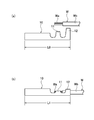
- FIG. 1 is an explanatory diagram of an evaluation method according to an embodiment of the present invention, (a) is a side view showing a state before crimping a terminal and an electric wire, (b) is a side view showing a state after crimping, (C) is a characteristic diagram showing the relationship between crimp height and terminal elongation due to crimping.
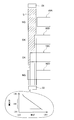
- FIG. 2 is an explanatory diagram showing a method of determination by the evaluation apparatus according to the embodiment of the present invention, including the relationship between terminal elongation and crimp height.
- FIG. 3 is an explanatory diagram showing how to make a determination by the evaluation apparatus according to another embodiment of the present invention.
- 4A and 4B are configuration diagrams of a general crimp terminal, in which FIG.
- FIG. 4A is a side view showing a state before crimping the terminal and an electric wire
- FIG. 4B is a side view showing a state after crimping.
- FIG. 5 is a cross-sectional view showing a state where a terminal and an electric wire are crimped by a crimper and an anvil.
- FIG. 6 is a cross-sectional view of the crimping portion between the terminal and the electric wire.
- FIG. 1 is an explanatory view of an evaluation method of an embodiment
- FIG. 1 (a) is a side view showing a state before crimping a terminal and an electric wire
- FIG. 1 (b) is a side view showing a state after crimping
- FIG. 1C is a characteristic diagram showing the relationship between crimp height and terminal elongation due to crimping.
- the structure of the terminal 10 and the structure of the electric wire W are the same as that of what was shown in FIG. 4, those description is abbreviate
- the total length L0 of the terminal 10 before crimping is grasped in advance, and the total length L1 of the terminal 10 after crimping is detected by means such as a sensor or a switch.
- the elongation of the terminal 10 after crimping relative to the length of the terminal 10 before crimping is detected by subtracting the total length L0 of the terminal 10 before crimping from the total length L1 of the terminal 10 after crimping.
- the evaluation method of the present embodiment utilizes the fact that there is a correlation between the crimp height C / H due to crimping and the elongation of the terminal 10, and instead of the lower limit value and the upper limit value of the crimp height C / H.
- the lower limit value and upper limit value of the terminal elongation are set, and whether or not the quality of the crimping part is good is determined by whether or not the elongation of the terminal 10 measured after crimping is within the allowable range between the lower limit value and the upper limit value. Therefore, the crimping part can be easily evaluated. That is, since it is easier to measure the length of the terminal 10 than to measure the crimp height C / H, automation can be easily realized, thereby enabling 100% inspection. As a result, all the performances of the crimped product can be guaranteed.
- FIG. 2 As a specific evaluation apparatus for carrying out this method, for example, the one shown in FIG. 2 can be considered.
- the detection means 20 described above is provided in a form attached to a measurement table (not shown).
- the measurement table is a table on which the terminal 10 can be set with reference to one end in the length direction (that is, the rear end connected to the electric wire).
- the position of the other end (that is, the tip) in the length direction of the terminal 10 set on the measurement table is defined based on the lower limit value and the upper limit value of elongation set in advance for the terminal after crimping. It is detected whether it is within the permissible region (ie, permissible range) S.
- the detection means 20 turns on a display device such as a lamp with a determination of “OK”.
- the detection means 20 determines “No (NG)”.
- the display device such as a lamp is not turned on. Therefore, the quality of the crimping part can be evaluated based on whether or not the lamp is lit.
- these determination contents are set in advance so as to coincide with the determination contents by the crimp height C / H. That is, since the crimp height C / H of the conductor crimping portion by the wire barrel 11A shown in the first stage and the wire barrel 11D shown in the fourth stage exceeds the upper limit value or the lower limit value, the determination is “No (NG)”. Since the crimp height C / H of the conductor crimping portion by the wire barrels 11B and 11C shown in the second and third stages is within the upper limit value and the lower limit value, the determination is “good (OK)”. is there.
- FIG. 3 shows an example of an evaluation apparatus according to another embodiment.
- an optical detection mechanism in which the light emitting unit 31 and the light receiving unit 32 are paired is used as a detection means.
- the light emitted from the light emitting unit 31 enters the light receiving unit 32, and the tip of the terminal 10 set on the measurement table enters the middle of the light path. Therefore, the received light amount is reduced by the area where the tip of the terminal 10 blocks the light entering the light receiving unit 32 from the light emitting unit 31.
- the range of the amount of received light corresponding to the upper limit value and the lower limit value of the extension of the terminal 10 can be set. By measuring, the elongation of the terminal 10 can be detected, and based on this, the quality of the crimping part can be evaluated by a determination means (not shown).
- the quality of the crimping part can be easily evaluated by detecting the elongation of the terminal 10 by the detecting means, that is, the light emitting part 31 and the light receiving part 32, and determining the extent of the elongation by the judging means. it can. That is, as shown in FIG. 3, since the terminal 10A shown in the first stage does not block the light emitted from the issuing unit 31, it does not reach the received light amount corresponding to the lower limit value of the terminal elongation, The determination means determines “No (NG)”.
- the received light amount is within the range of the received light amount corresponding to the upper limit value and the lower limit value of the extension of the terminal, so the determination means is “good (OK)”. Is determined. And since terminal 10D shown in the 4th stage has interrupted all the light discharge
- the crimping part evaluation method and crimping part evaluation apparatus for electric wires and terminals according to the present invention are effective in determining the quality of the crimping part when crimping the electric wires and terminals used as parts for automobiles and the like.
- Terminal 11 Terminal 11
- Terminal crimping part 12
- Insulation barrel (Coating caulking part)
- W Electric wire Wa Conductor Wb Insulation coating
- Detection means 31
- Light emitting part (detection means) 32
Landscapes
- Engineering & Computer Science (AREA)
- Manufacturing & Machinery (AREA)
- Manufacturing Of Electrical Connectors (AREA)
Abstract
Description
11 ワイヤバレル(端子加締部)
12 インシュレーションバレル(被覆加締部)
W 電線
Wa 導体
Wb 絶縁被覆
20 検出手段
31 発光部(検出手段)
32 受光部(検出手段)
Claims (3)
- 電線と端子の圧着部を評価する方法であって、
圧着後の前記端子の長さを測定することで、圧着前の前記端子の長さに対する圧着後の端子の伸びを検出し、その伸びが予め設定された下限値と上限値の間の許容範囲内にあるとき「良」と判定し、許容範囲外にあるとき「否」と判定する電線と端子の圧着部評価方法。 - 電線と端子の圧着部を評価する装置であって、
前記端子をその長さ方向の一端を基準にしてセットする測定台と、該測定台にセットされた前記端子の長さ方向の他端の位置が、圧着後の端子について予め設定された伸びの下限値と上限値に基づいて規定された許容範囲内にあるか否かを検出する検出手段と、を具備する電線に対する端子の圧着性能評価装置。 - 電線と端子の圧着部を評価する装置であって、
圧着前の端子の長さに対する圧着後の端子の長さ方向の伸びを検出する検出手段と、該検出手段の検出した伸びが、予め設定された下限値と上限値の間の許容範囲内にあるとき「良」と判定し、許容範囲外にあるとき「否」と判定する判定手段と、を具備する電線と端子の圧着部評価装置。
Priority Applications (2)
| Application Number | Priority Date | Filing Date | Title |
|---|---|---|---|
| US13/379,810 US9027401B2 (en) | 2009-06-22 | 2010-06-15 | Method of evaluating a clamping portion of an electric wire and a terminal, and device for evaluating the clamping portion |
| CN201080027536.2A CN102804523B (zh) | 2009-06-22 | 2010-06-15 | 评估电线与端子的压接部的方法以及评估该压接部的装置 |
Applications Claiming Priority (2)
| Application Number | Priority Date | Filing Date | Title |
|---|---|---|---|
| JP2009-147734 | 2009-06-22 | ||
| JP2009147734A JP5297277B2 (ja) | 2009-06-22 | 2009-06-22 | 電線と端子の圧着部評価方法および装置 |
Publications (1)
| Publication Number | Publication Date |
|---|---|
| WO2010150684A1 true WO2010150684A1 (ja) | 2010-12-29 |
Family
ID=43386454
Family Applications (1)
| Application Number | Title | Priority Date | Filing Date |
|---|---|---|---|
| PCT/JP2010/060145 Ceased WO2010150684A1 (ja) | 2009-06-22 | 2010-06-15 | 電線と端子の圧着部評価方法および圧着部評価装置 |
Country Status (4)
| Country | Link |
|---|---|
| US (1) | US9027401B2 (ja) |
| JP (1) | JP5297277B2 (ja) |
| CN (1) | CN102804523B (ja) |
| WO (1) | WO2010150684A1 (ja) |
Cited By (2)
| Publication number | Priority date | Publication date | Assignee | Title |
|---|---|---|---|---|
| EP2511648A1 (de) * | 2011-04-12 | 2012-10-17 | Komax Holding AG | Messanordnung und Verfahren zur Bestimmung mindestens der Crimphöhe eines Leitercrimps |
| DE102024110297A1 (de) | 2023-04-17 | 2024-10-17 | Yazaki Corporation | Steckverbinder |
Families Citing this family (3)
| Publication number | Priority date | Publication date | Assignee | Title |
|---|---|---|---|---|
| WO2014023879A1 (fr) * | 2012-08-08 | 2014-02-13 | Clara Vision | Support et boitier de prise de vue notamment pour le controle de qualite de sertissage de câbles electriques |
| JP6453834B2 (ja) * | 2016-11-17 | 2019-01-16 | 矢崎総業株式会社 | 端子検査装置 |
| CN108534637B (zh) * | 2018-03-12 | 2021-01-08 | 广东美的暖通设备有限公司 | 端子压接质量评估装置、评估方法及端子压接系统 |
Citations (1)
| Publication number | Priority date | Publication date | Assignee | Title |
|---|---|---|---|---|
| JPS61133844A (ja) * | 1984-12-03 | 1986-06-21 | Shin Meiwa Ind Co Ltd | 端子圧着電線の端子圧着部検査方法 |
Family Cites Families (13)
| Publication number | Priority date | Publication date | Assignee | Title |
|---|---|---|---|---|
| JP2686449B2 (ja) * | 1988-04-28 | 1997-12-08 | 三和テッキ株式会社 | 電線とスリーブの圧縮接続装置 |
| US4856186A (en) * | 1988-11-04 | 1989-08-15 | Amp Incorporated | Apparatus and method for determination of crimp height |
| US5195042A (en) * | 1990-06-27 | 1993-03-16 | Burndy Corporation | Apparatus and method for controlling crimping of articles |
| US5491994A (en) * | 1991-12-11 | 1996-02-20 | Diamond Die & Mold Company | Crimp height monitor |
| JP3873445B2 (ja) * | 1997-05-28 | 2007-01-24 | 株式会社明電舎 | 圧着端子検査装置 |
| JP3538701B2 (ja) * | 1999-02-10 | 2004-06-14 | 住友電装株式会社 | 端子圧着状態検査装置およびそれを備えた端子圧着装置 |
| DE10127854B4 (de) * | 2000-06-12 | 2006-02-02 | Yazaki Corp. | Verfahren zur Überprüfung des Crimpzustands einer Crimpanschlußklemme und Crimpanschlußklemme hierfür |
| JP4031214B2 (ja) | 2001-03-19 | 2008-01-09 | 矢崎総業株式会社 | 端子圧着状態判別方法 |
| CN1297044C (zh) | 2001-06-15 | 2007-01-24 | 矢崎总业株式会社 | 接线端压接状态的测试方法 |
| JP4436053B2 (ja) | 2003-02-13 | 2010-03-24 | 矢崎総業株式会社 | 圧着端子の圧着状況推定装置と圧着端子の良否判定装置 |
| JP4657880B2 (ja) | 2005-10-13 | 2011-03-23 | 新明和工業株式会社 | 端子圧着不良検出装置の圧着不良判定データ作成方法および圧着不良判定データ検査方法 |
| EP1837622B1 (de) * | 2006-03-16 | 2009-04-22 | komax Holding AG | Verfahren und Einrichtung zur Bestimmung der geometrischen Daten einer Kabelbestückung |
| JP4691058B2 (ja) * | 2007-03-20 | 2011-06-01 | 古河電気工業株式会社 | 端子変形検出方法及び端子変形検出装置 |
-
2009
- 2009-06-22 JP JP2009147734A patent/JP5297277B2/ja not_active Expired - Fee Related
-
2010
- 2010-06-15 US US13/379,810 patent/US9027401B2/en active Active
- 2010-06-15 CN CN201080027536.2A patent/CN102804523B/zh not_active Expired - Fee Related
- 2010-06-15 WO PCT/JP2010/060145 patent/WO2010150684A1/ja not_active Ceased
Patent Citations (1)
| Publication number | Priority date | Publication date | Assignee | Title |
|---|---|---|---|---|
| JPS61133844A (ja) * | 1984-12-03 | 1986-06-21 | Shin Meiwa Ind Co Ltd | 端子圧着電線の端子圧着部検査方法 |
Cited By (2)
| Publication number | Priority date | Publication date | Assignee | Title |
|---|---|---|---|---|
| EP2511648A1 (de) * | 2011-04-12 | 2012-10-17 | Komax Holding AG | Messanordnung und Verfahren zur Bestimmung mindestens der Crimphöhe eines Leitercrimps |
| DE102024110297A1 (de) | 2023-04-17 | 2024-10-17 | Yazaki Corporation | Steckverbinder |
Also Published As
| Publication number | Publication date |
|---|---|
| CN102804523B (zh) | 2015-04-08 |
| JP5297277B2 (ja) | 2013-09-25 |
| US20120146659A1 (en) | 2012-06-14 |
| JP2011003503A (ja) | 2011-01-06 |
| CN102804523A (zh) | 2012-11-28 |
| US9027401B2 (en) | 2015-05-12 |
Similar Documents
| Publication | Publication Date | Title |
|---|---|---|
| US9667014B2 (en) | Method of manufacturing a connection structural body | |
| JP5297277B2 (ja) | 電線と端子の圧着部評価方法および装置 | |
| KR880014359A (ko) | 프레스성형에 의하여 성형한 공작물의 성형불량 검출방법 및 이 방법을 이용한 단자압착장치 | |
| US20140173887A1 (en) | Process for Nondestructive Evaluation of the Quality of a Crimped Wire Connector | |
| WO2011004704A1 (ja) | 端子圧着装置 | |
| KR101237292B1 (ko) | 전자기기용 하네스 케이블의 검사방법 및 그 장치 | |
| PL201070B1 (pl) | Sposób i urządzenie do monitorowania procedury obciskania metalowych łączników na rdzeniu izolatora elektrycznego | |
| CN103682936B (zh) | 端子压接状态的检查方法及其检查装置 | |
| JP5290831B2 (ja) | 圧着端子及びその巻込み状態検査方法 | |
| WO2009016851A1 (ja) | 端子圧着装置、端子圧着電線の製造方法及び端子圧着電線 | |
| CN109004491B (zh) | 端子插入方法和端子插入装置 | |
| JP3866015B2 (ja) | 圧着端子及びその圧着検査方法 | |
| US11223178B2 (en) | Terminal displacement amount detection method, terminal insertion method, terminal displacement amount detection device, and terminal insertion device | |
| JP2011049051A (ja) | 端子金具 | |
| CN205066709U (zh) | 线束接插件视频检测系统 | |
| US10644483B2 (en) | Method of inspecting spark plug and method of manufacturing spark plug | |
| WO2017138115A1 (ja) | 端子圧着不良検出装置 | |
| JP5390968B2 (ja) | 端子圧着装置 | |
| JP2010205697A (ja) | 高強度細径線用圧着端子 | |
| JP2012204102A (ja) | 端子圧着装置 | |
| JP5437775B2 (ja) | 端子圧着装置 | |
| CN105319221A (zh) | 导线压接质量检测方法及装置 | |
| TWI865968B (zh) | 陶瓷電線裂痕測試方法 | |
| JP5113382B2 (ja) | 圧着工具の検査装置 | |
| JP2002214121A (ja) | 絶縁劣化診断方法 |
Legal Events
| Date | Code | Title | Description |
|---|---|---|---|
| WWE | Wipo information: entry into national phase |
Ref document number: 201080027536.2 Country of ref document: CN |
|
| 121 | Ep: the epo has been informed by wipo that ep was designated in this application |
Ref document number: 10792002 Country of ref document: EP Kind code of ref document: A1 |
|
| WWE | Wipo information: entry into national phase |
Ref document number: 13379810 Country of ref document: US |
|
| NENP | Non-entry into the national phase |
Ref country code: DE |
|
| 122 | Ep: pct application non-entry in european phase |
Ref document number: 10792002 Country of ref document: EP Kind code of ref document: A1 |