WO2010147212A1 - 詰替え容器 - Google Patents
詰替え容器 Download PDFInfo
- Publication number
- WO2010147212A1 WO2010147212A1 PCT/JP2010/060373 JP2010060373W WO2010147212A1 WO 2010147212 A1 WO2010147212 A1 WO 2010147212A1 JP 2010060373 W JP2010060373 W JP 2010060373W WO 2010147212 A1 WO2010147212 A1 WO 2010147212A1
- Authority
- WO
- WIPO (PCT)
- Prior art keywords
- laminate
- main body
- refill container
- spout
- nozzle
- Prior art date
- Legal status (The legal status is an assumption and is not a legal conclusion. Google has not performed a legal analysis and makes no representation as to the accuracy of the status listed.)
- Ceased
Links
Images

















Classifications
-
- B—PERFORMING OPERATIONS; TRANSPORTING
- B65—CONVEYING; PACKING; STORING; HANDLING THIN OR FILAMENTARY MATERIAL
- B65D—CONTAINERS FOR STORAGE OR TRANSPORT OF ARTICLES OR MATERIALS, e.g. BAGS, BARRELS, BOTTLES, BOXES, CANS, CARTONS, CRATES, DRUMS, JARS, TANKS, HOPPERS, FORWARDING CONTAINERS; ACCESSORIES, CLOSURES, OR FITTINGS THEREFOR; PACKAGING ELEMENTS; PACKAGES
- B65D59/00—Plugs, sleeves, caps, or like rigid or semi-rigid elements for protecting parts of articles or for bundling articles, e.g. protectors for screw-threads, end caps for tubes or for bundling rod-shaped articles
- B65D59/04—Sleeves, e.g. postal tubes
-
- B—PERFORMING OPERATIONS; TRANSPORTING
- B65—CONVEYING; PACKING; STORING; HANDLING THIN OR FILAMENTARY MATERIAL
- B65D—CONTAINERS FOR STORAGE OR TRANSPORT OF ARTICLES OR MATERIALS, e.g. BAGS, BARRELS, BOTTLES, BOXES, CANS, CARTONS, CRATES, DRUMS, JARS, TANKS, HOPPERS, FORWARDING CONTAINERS; ACCESSORIES, CLOSURES, OR FITTINGS THEREFOR; PACKAGING ELEMENTS; PACKAGES
- B65D33/00—Details of, or accessories for, sacks or bags
- B65D33/06—Handles
- B65D33/10—Handles formed of similar material to that used for the bag
- B65D33/105—U-shaped
-
- B—PERFORMING OPERATIONS; TRANSPORTING
- B65—CONVEYING; PACKING; STORING; HANDLING THIN OR FILAMENTARY MATERIAL
- B65D—CONTAINERS FOR STORAGE OR TRANSPORT OF ARTICLES OR MATERIALS, e.g. BAGS, BARRELS, BOTTLES, BOXES, CANS, CARTONS, CRATES, DRUMS, JARS, TANKS, HOPPERS, FORWARDING CONTAINERS; ACCESSORIES, CLOSURES, OR FITTINGS THEREFOR; PACKAGING ELEMENTS; PACKAGES
- B65D75/00—Packages comprising articles or materials partially or wholly enclosed in strips, sheets, blanks, tubes or webs of flexible sheet material, e.g. in folded wrappers
- B65D75/52—Details
- B65D75/54—Cards, coupons or other inserts or accessories
- B65D75/56—Handles or other suspension means
- B65D75/566—Hand holes or suspension apertures
-
- B—PERFORMING OPERATIONS; TRANSPORTING
- B65—CONVEYING; PACKING; STORING; HANDLING THIN OR FILAMENTARY MATERIAL
- B65D—CONTAINERS FOR STORAGE OR TRANSPORT OF ARTICLES OR MATERIALS, e.g. BAGS, BARRELS, BOTTLES, BOXES, CANS, CARTONS, CRATES, DRUMS, JARS, TANKS, HOPPERS, FORWARDING CONTAINERS; ACCESSORIES, CLOSURES, OR FITTINGS THEREFOR; PACKAGING ELEMENTS; PACKAGES
- B65D75/00—Packages comprising articles or materials partially or wholly enclosed in strips, sheets, blanks, tubes or webs of flexible sheet material, e.g. in folded wrappers
- B65D75/52—Details
- B65D75/58—Opening or contents-removing devices added or incorporated during package manufacture
- B65D75/5816—Opening or contents-removing devices added or incorporated during package manufacture for tearing a corner or other small portion next to the edge, e.g. a U-shaped portion
- B65D75/5822—Opening or contents-removing devices added or incorporated during package manufacture for tearing a corner or other small portion next to the edge, e.g. a U-shaped portion and defining, after tearing, a small dispensing spout, a small orifice or the like
-
- B—PERFORMING OPERATIONS; TRANSPORTING
- B65—CONVEYING; PACKING; STORING; HANDLING THIN OR FILAMENTARY MATERIAL
- B65D—CONTAINERS FOR STORAGE OR TRANSPORT OF ARTICLES OR MATERIALS, e.g. BAGS, BARRELS, BOTTLES, BOXES, CANS, CARTONS, CRATES, DRUMS, JARS, TANKS, HOPPERS, FORWARDING CONTAINERS; ACCESSORIES, CLOSURES, OR FITTINGS THEREFOR; PACKAGING ELEMENTS; PACKAGES
- B65D75/00—Packages comprising articles or materials partially or wholly enclosed in strips, sheets, blanks, tubes or webs of flexible sheet material, e.g. in folded wrappers
- B65D75/52—Details
- B65D75/58—Opening or contents-removing devices added or incorporated during package manufacture
- B65D75/5861—Spouts
- B65D75/5866—Integral spouts
-
- B—PERFORMING OPERATIONS; TRANSPORTING
- B65—CONVEYING; PACKING; STORING; HANDLING THIN OR FILAMENTARY MATERIAL
- B65D—CONTAINERS FOR STORAGE OR TRANSPORT OF ARTICLES OR MATERIALS, e.g. BAGS, BARRELS, BOTTLES, BOXES, CANS, CARTONS, CRATES, DRUMS, JARS, TANKS, HOPPERS, FORWARDING CONTAINERS; ACCESSORIES, CLOSURES, OR FITTINGS THEREFOR; PACKAGING ELEMENTS; PACKAGES
- B65D77/00—Packages formed by enclosing articles or materials in preformed containers, e.g. boxes, cartons, sacks or bags
- B65D77/04—Articles or materials enclosed in two or more containers disposed one within another
- B65D77/06—Liquids or semi-liquids or other materials or articles enclosed in flexible containers disposed within rigid containers
- B65D77/062—Flexible containers disposed within polygonal containers formed by folding a carton blank
- B65D77/065—Spouts, pouring necks or discharging tubes fixed to or integral with the flexible container
Definitions
- the present invention relates to a refill container for storing toiletries such as liquid detergents and softeners, foods such as cooking oil and instant coffee.
- Toiletries such as liquid detergents and softeners, and foods such as edible oil and instant coffee are stored in dedicated containers that are easy to use.
- the dedicated container has a solid structure and is therefore expensive, so a product with a refill container that refills only the contents is sold separately so that it can be used repeatedly when the contents are gone. It is often done.
- liquid detergent containers need to be weighed and taken out each time they are used, so a rigid plastic container with a nozzle at the spout is repeatedly used so that it can be easily poured into a lightweight cup. It is used as a container to be used.
- a flexible container made of a flexible packaging film, a container in which a spout is formed, or a container attached with a stopper is generally used. ing.
- a rigid container that is used repeatedly is designed so that it can be easily poured out.Therefore, in consideration of the convenience of the refilling operation of refilling the contents from the refilling container, There wasn't.
- the refill container is not necessarily considering the convenience of the refilling operation because the emphasis is on manufacturing at low cost.
- the refill container can be opened using the nozzle provided in the container to be used repeatedly, and since the refill container is self-supporting during refilling, it does not need to be held by hand.
- Containers have been proposed.
- This hand-held refillable container is a refillable container including a coupling member that is detachably connected to an opening of a container that is repeatedly used and a container sealing member that seals the refillable container body (see Patent Document 1). .
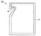
- a packaging bag 60 which is a refill container formed by sealing the periphery of two packaging films 61 as shown in FIG. 29, is advantageous.
- the packaging bag 60 can be provided with a spout 62 having an arbitrary width corresponding to the diameter of the container.
- the opening part is pulled to both ends where the film is sealed, and the front and back films are in a pseudo-adherent state. It becomes. For this reason, there exists a problem that a spout will be obstruct
- the spout is easily bent and the spout is detached from the container that is repeatedly used during the refilling operation.
- Patent Document 2 In order to solve the problem that the spout is blocked or bent, a part different from the film is inserted into the spout (see Patent Document 2), or the film near the spout is inflated. Many proposals have been made to secure the opening area by adopting a shape (see Patent Document 3).
- these packaging bags have the problem that the process of attaching separate members and the process of applying deep embossing to the film increase, and that the packaging bags cannot be neatly stacked in the packaging bag supply section at the time of filling.
- an object of the present invention is to provide a refill container that is easy, quick and reliable in refill operation.
- the refill container is configured as follows.
- a refill container comprising a laminate having at least a base material and a sealant layer, wherein the one laminate is folded at the top with the sealant layer inside.
- the body is configured such that the sealant layers face each other and the periphery is sealed, and the bent portion is provided with a spout seal portion at a lower portion thereof, and the outflow path of contents leading to the spout together with the spout seal portion Form.
- a refill container comprising a laminate having at least a base material and a sealant layer, wherein one of the laminates is folded with the sealant layer inside, a bent portion; A main body surface laminate formed by the folded laminate, and a main body back laminate formed by the folded laminate, the main body surface laminate and the main body back laminate, The sealant layers are opposed to each other, and the periphery is sealed, and the bent portion is provided with a spout seal portion at the bottom thereof, and forms a spout nozzle for pouring the contents together with the spout seal portion.
- the tip of the pouring nozzle has a scheduled opening line at the tip, and a spout is formed by cutting along the scheduled opening line, and the planned opening line length is A (mm).
- the opening width of the spout and B (mm) satisfy the relationship of A-4 (mm) ⁇ B (mm) ⁇ A-0.5 (mm).
- a refill container comprising a laminate having at least a base material and a sealant layer, wherein one of the laminates is folded with the sealant layer inside, a bent portion; A main body surface laminate formed by the folded laminate, and a main body back laminate formed by the folded laminate, the main body surface laminate and the main body back laminate, The sealant layers are opposed to each other, and the periphery is sealed, and the bent portion is provided with a spout seal portion at the bottom thereof, and forms a spout nozzle for pouring the contents together with the spout seal portion.
- the tip of the pouring nozzle has a scheduled opening line at the tip, and a spout is formed by cutting along the planned opening line, and the width of the spout is C (mm).
- the opening cross-sectional area of the mouth when the D (mm 2) satisfies the relationship of 1/10 ⁇ (C 2 / ⁇ ) (mm 2) ⁇ D (mm 2) ⁇ C 2 / ⁇ (mm 2) .
- a refill container comprising a laminate having at least a base material and a sealant layer, wherein one of the laminates is folded with the sealant layer inside, a bent portion; A main body surface laminate formed by the folded laminate, and a main body back laminate formed by the folded laminate, the main body surface laminate and the main body back laminate, The sealant layers are opposed to each other, and the periphery is sealed, and the bent portion is provided with a spout seal portion at the bottom thereof, and forms a spout nozzle for pouring the contents together with the spout seal portion.
- the tip of the pouring nozzle is sealed by a pouring nozzle tip seal portion, and a pouring outlet is formed by cutting along the planned opening line, and the pouring nozzle
- the laminate to be formed is provided with an outward convex, band-like or streak-like convex emboss, and the convex embossing is formed on the planned opening line when the length of the planned opening line is E.
- the center exists in the range of two-thirds of E from the exit nozzle seal part, and exists at least continuously from the planned opening line to the extended line of the punched part seal part.
- the present invention can provide a refill container that is easy, quick and reliable in refilling operation without using a separate member such as a plug.
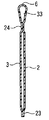
- FIG. 1 is a schematic diagram showing the configuration of a refill container according to the first embodiment of the present invention.
- FIG. 2A is a cross-sectional view schematically showing the configuration of the II-II cross section of the refill container.
- FIG. 2B is a cross-sectional view schematically showing a layer configuration of a laminate constituting the refill container.
- FIG. 3 is a schematic diagram showing the configuration of a refill container according to the second embodiment of the present invention.
- FIG. 4A is a cross-sectional view schematically showing the configuration of the IV-IV cross section of the refill container.
- FIG. 4B is a cross-sectional view schematically showing a state in which the refill container is opened.
- FIG. 5 is a schematic diagram showing a configuration of a refill container according to the third embodiment of the present invention.
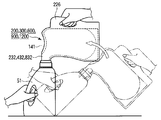
- FIG. 6 is a schematic view showing an example of a series of refill operations using the refill container.
- FIG. 7 is a schematic view showing an example of a series of refill operations using the refill container.
- FIG. 8 is a schematic view showing an example of a series of refill operations using the refill container.
- FIG. 9 is a schematic view showing a spout portion in a refill container according to the fourth embodiment of the present invention.
- FIG. 10 is a schematic diagram showing a configuration of a refill container according to the fifth embodiment of the present invention.
- FIG. 11 is a cross-sectional view schematically showing the configuration of the XI-XI cross section of the refill container.
- FIG. 12A is an enlarged view showing a configuration of a dispensing nozzle of the refill container.
- FIG. 12B is a cross-sectional view schematically showing the configuration of the spout of the spout nozzle.
- FIG. 13A is an enlarged view showing a configuration of a dispensing nozzle of a conventional refill container.
- FIG. 13B is a cross-sectional view schematically showing the configuration of the spout of the spout nozzle.
- FIG. 14 is a schematic diagram showing a configuration of a refill container according to the sixth embodiment of the present invention.
- FIG. 15A is a cross-sectional view schematically showing the configuration of the XV-XV cross section of the refill container.
- FIG. 15B is a cross-sectional view schematically showing a state in which the refill container is opened.
- FIG. 16 is a schematic diagram showing a configuration of a refill container according to the seventh embodiment of the present invention.
- FIG. 17 is a schematic diagram showing a configuration of a refill container according to the seventh embodiment of the present invention.
- FIG. 18A is an enlarged view showing a configuration of a spout portion of the refill container.
- FIG. 18B is a cross-sectional view schematically showing the configuration of the XVII-XVII cross section of the pouring outlet.
- FIG. 18C is a cross-sectional view schematically showing a state in which the area of the pouring outlet is maximized by an XVII-XVII cross section.
- FIG. 19 is a schematic diagram showing a configuration of a refill container according to the eleventh embodiment of the present invention.
- FIG. 20 is a cross-sectional view schematically showing the configuration of the IIX-IIX cross section of the refill container.
- FIG. 21 is an enlarged view for explaining the configuration of the convex embossing of the dispensing nozzle of the refill container.
- FIG. 22 is an enlarged view for explaining the configuration of the concave embossing of the dispensing nozzle of the refill container.
- FIG. 23 is a modified example of the pouring nozzle of the refill container, and is an enlarged view showing a configuration of convex embossing and concave embossing.
- FIG. 20 is a cross-sectional view schematically showing the configuration of the IIX-IIX cross section of the refill container.
- FIG. 21 is an enlarged view for explaining the configuration of the convex embossing of the dispensing nozzle of the refill container.
- FIG. 24A is an enlarged cross-sectional view showing an example of the configuration of the dispensing nozzle of the refill container.
- FIG. 24B is a cross-sectional view showing an enlarged configuration of an example of a dispensing nozzle of the refill container.
- FIG. 24C is an enlarged cross-sectional view showing an example of the configuration of the dispensing nozzle 1032A of the refill container 1000.
- FIG. 24D is a cross-sectional view showing an enlarged configuration of an example of the dispensing nozzle 1032A of the refill container 1000A.
- FIG. 25 is a schematic diagram showing a configuration of a refill container according to the twelfth embodiment of the present invention.
- FIG. 25 is a schematic diagram showing a configuration of a refill container according to the twelfth embodiment of the present invention.
- FIG. 26A is a cross-sectional view schematically showing a configuration of a cross-section XXVI-XXVI of the refill container.
- FIG. 26B is a sectional view of the refill container taken along the line XXVI-XXVI, schematically showing a state in which the refill container is opened.
- FIG. 27 is a schematic diagram showing a configuration of a refill container according to a thirteenth embodiment of the present invention.
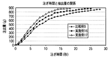
- FIG. 28 is a graph showing an example of the relationship between the pouring time and the pouring amount depending on the presence or absence of embossing in the pouring nozzle of the refill container.
- FIG. 29 is a schematic view showing an example of a conventional refill container.
- FIG. 1 is a plan view schematically showing a refill container 1 according to the first embodiment of the present invention.
- FIG. 2A is a cross-sectional view schematically showing a II-II cross section in FIG. 1 of the refill container 1.
- 2B is a cross-sectional view of the refill container 1 taken along the line II-II in FIG. 1 and schematically showing the configuration of the stacked body of the refill container 1.
- FIG. 1 is a plan view schematically showing a refill container 1 according to the first embodiment of the present invention.
- FIG. 2A is a cross-sectional view schematically showing a II-II cross section in FIG. 1 of the refill container 1.
- 2B is a cross-sectional view of the refill container 1 taken along the line II-II in FIG. 1 and schematically showing the configuration of the stacked body of the refill container 1.
- FIG. 1 is a plan view schematically showing a refill container 1 according to the first embodiment of the present invention.
- FIG. 2A is a cross-sectional view
- the refill container 1 includes a main body surface laminate 2, a main body back laminate 3, a bent portion 6, and a seal portion 20. Moreover, the refill container 1 is formed with the laminated body 10 which has at least the base material 11 and the sealant layer 12, as shown to FIG. 2B.
- the refill container 1 bends a single laminate 10 loosely at the top with the sealant layers 12 facing each other so that the sealant layer 12 is on the inside.
- the refill container 1 seals the periphery of the folded laminate 10.
- the refill container 1 includes a folded portion 6 folded at the top, and a main body surface laminate 2 that is one main surface with the folded portion 6 as a boundary,
- the main body back surface laminated body 3 which is the other main surface is formed with the bent portion 6 as a boundary.
- the main body surface laminate 2 is a film that forms the main body surface.
- the main body back surface laminated body 3 is a film which forms a main body surface.
- the refill container 1 seals the circumference
- the opening part for filling the content into the inside is abbreviate
- the opening may be provided in any one of the seal portions 20, and the portion of the seal portion 20 may be sealed after the contents are filled.
- the main body front surface laminate 2 and the main body back surface laminate 3 respectively form the front and back of the refill container 1. Moreover, the main body surface laminated body 2 and the main body back surface laminated body 3 are formed in the bag shape by sealing the side edge and the lower edge by the seal part 20.
- the main body surface laminate 2 is a part of the laminate 10 and a film on the main body surface.
- the main body back surface laminated body 3 is a part of the laminated body 10, and is a film of a main body back surface.
- the seal part 20 includes a side seal part 22 and a bottom seal part 23.
- the side seal portion 22 seals the side edges of the main body surface laminate 2 and the main body back laminate 3.
- the bottom seal portion 23 seals the lower edges of the main body surface laminate 2 and the main body back laminate 3.
- the seal portion 20 includes a spout seal portion 24 that seals from a part above one side edge of the main body surface laminate 2 and the main body back laminate 3 to a part below the bent portion 6.
- the bent portion 6 is formed by a bent end side of the laminate 10 and a spout seal portion 24 provided below the end side.
- the spout 31 and the outflow passage 33 of the contents are formed by the end portion of the laminate 10 and the spout seal portion 24.
- the spout 31 is opened by excising a part of the side seal portion 22.
- the outflow passage 33 is formed in a horizontally long shape up to the spout 31.
- the laminated body 10 is, for example, a laminated film that is usually used for soft packaging bags.
- the base material 11 is a film layer of the base material.
- the base material 11 paper, metal foil, or synthetic resin film composed of one layer or several layers is used.
- the base material 11 may be a low-density polyethylene resin (LDPE), a high-density polyethylene resin (HDPE), a linear low-density polyethylene resin (LLDPE), a polypropylene resin (PP), or a polyolefin-based elastomer such as a polyolefin-based elastomer.
- LDPE low-density polyethylene resin
- HDPE high-density polyethylene resin
- LLDPE linear low-density polyethylene resin
- PP polypropylene resin
- a polyolefin-based elastomer such as a polyolefin-based elastomer.
- Polyester resins such as polyethylene terephthalate resin (PET), Polybutylene terephthalate resin (PBT), Polyethylene naphthalate resin (PEN), Cellulosic resins such as cellophane and cellulose triacetate (TAC), Polymethyl methacrylate (PMMA) ) Resin, ethylene-vinyl acetate copolymer resin (EVA), ionomer resin, polybutene resin, polyacrylonitrile resin, polyamide resin, polystyrene resin (PS), polyvinyl chloride resin (PVC), poly salt Vinylidene resin (PVDC), polycarbonate resin (PC), fluorine-based resin, synthetic resin films and paper, such as urethane resin, a metal foil or the like is used alone or combined.
- the base material 11 includes a printing layer and an adhesive layer as necessary.
- the paper high-quality paper, single-sided art paper, coated paper, cast coated paper, imitation paper, and the like can be used.
- embossing may be applied to the spout nozzle.
- embossing it was.
- the spout is stably opened, and embossing is not required. It is valid.
- the polyolefin layer resin is generally used for the sealant layer 12.
- the sealant layer 12 includes an ethylene resin such as a low density polyethylene resin, a medium density polyethylene resin, a linear low density polyethylene resin, an ethylene / vinyl acetate copolymer, an ethylene / ⁇ -olefin copolymer, Polypropylene resins such as homopolypropylene resins, propylene / ethylene random copolymers, propylene / ethylene block copolymers, propylene / ⁇ -olefin copolymers, and the like are used.
- the sealant layer 12 may be a multilayer film obtained by combining these resins.
- the structure of the laminate 10 include PET / printing layer / adhesive layer / stretched polyamide resin film (hereinafter abbreviated as ONY) / adhesive layer / LLDPE film, ONY / adhesive layer / Examples include LLDPE, ONY / adhesive layer / ONY / adhesive layer / LLDPE, paper / LDPE / aluminum foil / LDPE, paper / LDPE, and the like.
- the bent portion 6 is formed by loosely bending the single laminate 10, so that the bent portion 6 generates an elastic action to return the laminated film. That is, a restoring force is generated in the bent portion 6.
- the cross section of the outflow passage 33 is always in a state where the upper portion is swollen. For this reason, it becomes possible to ensure the cross-sectional area of the spout 31 widely, and it becomes possible to discharge a lot of contents at once.
- the cross section of the outflow passage 33 is expanded, the outflow passage 33 is less likely to be bent during the refilling operation.
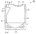
- FIG. 3 is a schematic view showing a refill container 100 according to the second embodiment of the present invention.
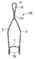
- FIG. 4A is a schematic cross-sectional view showing a IV-IV cross section of the refill container 100.
- FIG. 4B is a schematic cross-sectional view showing a IV-IV cross section in a state in which the container main body which is the refill container 100 is opened.
- the refill container 100 has a main body surface laminate 2, a main body back laminate 3, and a bottom tape 104.
- the refill container 100 has the sealant layers 12 facing each other and the periphery is sealed.
- the bottom tape 104 is made of the same material as that of the laminate 10.
- the bottom tape 104 is bent at the bottom of the container so that the sealant layer 12 is on the outside.
- One end of the bottom tape 104 forms a bottom seal portion 123 together with the main body surface laminate 2, and the other end is the main body.
- a bottom seal portion 123 is formed together with the back surface laminate 3 to constitute the bottom surface of the container.
- This type of packaging bag is called a so-called standing pouch. This standing pouch has the feature that a large-capacity container can be realized because the bottom surface widens greatly.
- the bending part 6 is formed by loosely bending one laminated body 10 at the top with the sealant layer inside, similarly to the bending part 6 of the refill container 1 described above.
- the bent portion 6 and the spout seal portion 124 provided at the lower portion of the bent portion 6 form an outflow passage 33 for the contents reaching the spout 31 in a horizontally long shape.
- the refill container 100 is provided with a filling opening 141 for opening a part of the bent portion 6 and filling the contents.
- the filling opening 141 is sealed after filling the contents.
- FIG. 3 shows a state in which the top opening 121 is formed by sealing the filling opening 141.
- the refill container 100 configured as described above, the content smoothly flows through the linear outflow passage 33 when the content is poured out by the bent portion 6, particularly when the content is liquid. For this reason, the refill container 100 enables quick extraction.
- the refill container 100 having a shape called a standing pouch is more effective by using the bent portion 6 that can be quickly poured out because the container has a large capacity.
- FIG. 5 is a schematic diagram showing a configuration of a refill container 200 according to the third embodiment of the present invention.
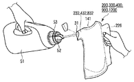
- FIG. 6 is a schematic diagram illustrating an example of a series of refilling operations using the refill container 300.
- FIG. 7 is a schematic diagram showing an example of a series of refilling operations using the refill container 300.
- FIG. 8 is a schematic diagram showing an example of a series of refilling operations using the refill container 300.
- the refill container 200 is formed as a dispensing nozzle 232 from which the outflow passage 33 protrudes by forming a punching portion 225 in the spout seal portion 224.
- the refill container 200 is provided with a handle 226 having a shape that fits in the punching section 225 on the side opposite to the side on which the dispensing nozzle 232 is formed.
- the laminated body 10 slit to a width approximately twice the width corresponding to the height of the refill container 200 is placed on the top with the sealant layer 12 surface inside. Bend gently and face each other.
- the main body front surface laminate 2 and the main body back surface laminate 3 are formed with the bent portion 6 as a boundary, and these are continuously supplied.
- the continuous supply means that the laminate 10 and the main body surface laminate 2 are formed by bending a single laminate 10 having a size in which a plurality of refill containers 200 are formed so that a plurality of refill containers 200 are formed. Supplying the back laminate 3.
- the bottom tape 104 folded in half so that the surface of the sealant layer 12 is on the outside is continuously supplied between the main body surface laminate 2 and the main body back laminate 3.
- the outline of the refill container 200, the punching portion 225, and the handle 226 are punched out to form a container.
- the refill container 200 includes a filling opening 141 for opening a part of the bent portion 6 and filling the contents.
- the outflow passage 33 is formed in the protruding dispensing nozzle 232 by providing the punching portion 225.
- This dispensing nozzle 232 can be inserted into a stopper portion of a container that is repeatedly used, for example.
- the shape of the punching process part 225 can select a suitable shape according to the structure of the stopper part periphery of the container used repeatedly.
- the punching portion 25 is a portion that is originally discarded, but as shown in FIG. 5, if the handle 226 has a shape that fits in the punching portion 225 of the adjacent refill container 200 at the time of manufacture, In particular, the handle 226 can be added without an increase in material. Since the handle 226 is present, the refilling operation can be performed with the handle 226, so that the refilling operation can be performed more safely and easily.
- the refill container 200 has a configuration in which the side seal part 22 is provided with the punching part 225 and the handle 226, it is difficult to provide the filling opening 141 having a sufficient width in addition to the bent part 6. It is. Therefore, it is preferable to provide the filling opening 141 at the bent portion 6.
- the refill container 200 of the present embodiment is held, the tip of the dispensing nozzle 32 is cut, and the spout 31 is opened.
- the nozzle 52 of the container 51 that is emptied repeatedly is inserted into the spout 31.
- the container 51 to be repeatedly used is a plastic container provided with a nozzle cap 53 having a nozzle 52.
- the pouring nozzle 232 of the refill container 200 is reliably inserted into the nozzle cap 53 of the container 51 to be used repeatedly.
- FIG. 8 when the entire arrangement is made so that the dispensing nozzle 232 is vertical while keeping the positional relationship between the container 51 and the refill container 200 to be repeatedly used constant, The contents are poured into the container 51 that is repeatedly used at once.
- the refill container according to the present invention can secure a large-area spout without using a special plastic spigot by providing the bent portion 6.
- the size of this spout can be freely designed according to the shape of the intended stopper used repeatedly, so it is extremely valuable as a dedicated refill container that can be quickly refilled. Is.
- FIG. 9 is a schematic diagram showing a portion of the spout 31 of the refill container 300 according to the fourth embodiment of the present invention.
- the refill container 300 is a configuration in which a half cut line 334 is provided in the pouring nozzle 332 on the outer surface of the main body front surface laminate 2 and the main body back surface laminate 3 in the portion to be the spout 31. By doing so, it becomes possible to easily form the spout 31 by tearing the portion of the half-cut line 334 by hand.
- the portion to be the spout 31 is a portion to be opened, and if the spout nozzle 332 is present as shown in FIG. 6, it is preferably provided at a position slightly retracted from the tip of the spout nozzle 332. This is because the tip of the pouring nozzle is easily held by hand.
- the half-cut line 334 is generally formed by a method using a blade or a method formed by laser processing. However, the half-cut line 334 is preferably formed by laser processing because the laser processing method can form uniform and stable cuts.
- Example 1 a specific example of the refill container 300 according to the present embodiment will be described as Example 1.
- Example 1 As the main body surface laminate 2 and the main body back laminate 3, a laminate 10 having the following configuration was used.
- a refill container 400 according to a fifth embodiment of the present invention will be described in detail with reference to FIGS. 10, 11, 12A, 12B, 13A, and 13B.
- symbol is attached
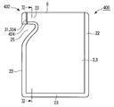
- FIG. 10 is a schematic diagram showing a configuration of a refill container 400 according to the fifth embodiment of the present invention.
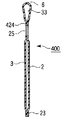
- FIG. 11 is a cross-sectional view schematically showing the configuration of the refill container 400 taken along the line XI-XI.
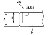
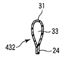
- FIG. 12A is an enlarged view showing the configuration of the dispensing nozzle 432 of the refill container 400.
- FIG. 12B is a cross-sectional view schematically showing the configuration of the spout 31 of the spout nozzle 432.
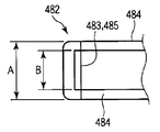
- FIG. 13A is an enlarged view showing a configuration of a dispensing nozzle 482 of a conventional refill container.
- FIG. 13B is a cross-sectional view schematically showing the configuration of the spout 483 of the spout nozzle 482.
- the refill container 400 includes a laminate 10 having at least a base material 11 and a sealant layer 12 as shown in FIGS. Moreover, the refill container 400 has the main body surface laminated body 2 and the main body back surface laminated body 3, as shown in FIG. 10, FIG. 11, each sealant layer 12 is made to oppose, and the circumference
- the bent portion 6 and the spout seal portion 424 form a spout nozzle 432 for pouring the contents.
- the spout 31 can be formed by cutting the tip of the spout nozzle 432 along the planned opening line 434.
- the refill container 400 has a length of A (mm) as the planned opening line of the dispensing nozzle 432, and B (mm) as the opening width of the spout 31. -4 (mm) ⁇ B (mm) ⁇ A ⁇ 0.5 (mm).
- This relational expression indicates that the width of the spout seal portion 424 is 0.5 mm or greater and 4 mm or less.
- a dimension and B dimension in FIG. 12A are numerical values measured in a state where the dispensing nozzle 432 is pressed flat. As shown in FIG. 12B, the actual cross-section of the pouring nozzle is in a state of bulging laterally due to the elasticity of the laminate 10.
- FIG. 13A is an enlarged view of a dispensing nozzle 482 of a conventional refill container.
- FIG. 13B is a schematic cross-sectional view of the spout 483 of the spout nozzle 482.
- the seal portions 484 exist above and below the spout 483
- the length A of the planned opening line 485 is wider than the opening width B.
- the spout 483 does not open widely, in addition to the problem that it is difficult to insert into the nozzle cap, there is a problem that the spoutability is poor.
- the main body surface laminate 2 and the main body back laminate 3 are sealed in the side seal part 22 and the bottom seal part 23 to form a bag shape.
- a filling opening for filling the contents is necessary, but the filling opening is omitted in FIG.
- a filling opening can be provided in the bottom seal part 23 or the side seal part 22.
- the unscheduled opening line 434 at the tip of the dispensing nozzle 32 is a virtual line indicating the unsealing position, but in order to clarify the unsealing position, a print display or the like may actually be performed.
- the half cut line 334 provided in the outer surface of the main body surface laminated body 2 and / or the main body back surface laminated body 3 may be used for the planned opening line 434.
- the portion to be the spout 31 is provided at a position slightly retracted from the tip of the spout nozzle 432. This is because the tip of the dispensing nozzle is easily held by hand.
- the spout seal portion 24 corresponding to the planned opening line 434 may be provided with a V-shaped or U-shaped notch or cut line, or the tip of the spout seal portion may be processed to be wide. By making the notch, the cut line, and the tip of the seal portion wide, the ease of opening the tip of the dispensing nozzle 432 is further improved.
- a refill container 500 according to a sixth embodiment of the present invention will be described in detail with reference to FIGS. 14, 15A and 15B.
- symbol is attached
- FIG. 14 is a schematic diagram showing a configuration of a refill container 500 according to the sixth embodiment of the present invention.
- FIG. 15A is a cross-sectional view schematically showing the configuration of the XV-XV cross section of the refill container 500.
- FIG. 15B is a cross-sectional view schematically showing an open state of the refill container 500.
- the refill container 500 includes the main body surface laminate 2, the main body back laminate 3, and the bottom tape 4, and the sealant layers are opposed to each other and the periphery is sealed.
- the bottom tape 4 is bent at the bottom of the container so that the sealant layer is on the outside.
- One end of the bottom tape 4 forms the bottom seal portion 123 together with the main body surface laminate 2, and the other end is the back surface of the main body.
- a bottom seal portion 123 is formed together with the laminate 3 to constitute the container bottom surface.
- This type of packaging bag is referred to as a so-called standing pouch, and has a feature that a large-capacity container can be realized because the bottom surface widens greatly.
- the bent portion 6 is formed by bending a single laminate at the top with the sealant layer inside.
- the bent portion 6 together with the spout seal portion 24 and the punching portion 525 forms an outflow passage 33 for contents reaching the spout 31. That is, the refill container 500 is formed in a shape in which the punching section 525 is provided in the refill container 100 described above. In addition, the refill container 500 has a dispensing nozzle 432.
- the refill container 500 is quicker, particularly when the contents are liquid, since the contents smoothly flow through the straight outflow passage 33 when the contents are poured out. Allows for dispensing. Further, the refill container 500 is formed in a shape called a standing pouch, and is more effective because the container has a large capacity.
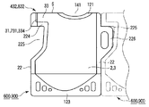
- FIG. 16 is a schematic diagram showing a configuration of a refill container 600 according to the seventh embodiment of the present invention.
- the refill container 600 of the present embodiment is pulled out on the side opposite to the punching portion 225 of the spout seal part 224 that forms the spout nozzle 32, similarly to the refill container 300 described above.
- a handle 226 having a shape that fits in the processing unit 25 is provided.
- the refill container 600 has not the extraction nozzle 232 of the refill container 300 but the extraction nozzle 432 of the refill container 400.
- the outflow path 33 is formed as a protruding dispensing nozzle 432 by forming the punching portion 225 in the spout seal portion 224.
- the shape of the punching process part 225 can select a suitable shape according to the structure of the stopper part periphery of the container used repeatedly.
- the laminated body 10 that is slit to a width approximately twice the width corresponding to the height of the container, like the refill containers 200 and 300, is used as the sealant layer 12.
- the main body front surface laminate 2 and the main body back surface laminate 3 are made to face each other with the surface facing inward and bent at the top. This is supplied continuously.
- the bottom tape 4 folded in half so that the sealant layer surface is on the outside is continuously supplied between the main body front surface laminate 2 and the main body back surface laminate 3, and after necessary sealing is performed, it is punched into a container.
- this refill container 600 a part of the bent portion 6 is cut open to form a filling opening 141 for filling the contents.
- the punched portion 25 and the handle 26 exist in the side seal portion 22, it is difficult to provide a filling opening having a sufficient width in addition to the bent portion 6. Therefore, it is preferable to provide the filling opening 41 at the bent portion 6.
- the refill container 600 is held, the tip of the dispensing nozzle 432 is cut, and the spout 31 is opened.
- the nozzle 52 of the container 51 that is emptied repeatedly is inserted into the spout 31.
- the pouring nozzle 32 of the refill container 600 is securely inserted into the nozzle cap 53 of the container 51 to be used repeatedly.
- FIG. 8 when the whole of the dispensing nozzle 32 is caused to be vertical while keeping the positional relationship between the container 51 and the refill container 600 to be used repeatedly constant, The contents are poured into the container 51 to be used repeatedly at once.
- the refill container 600 can secure a large-area spout without using a special plastic spout or the like. Since it can be designed freely according to the shape of the stopper of the container to be used repeatedly, it is extremely valuable as a dedicated refill container that can be quickly refilled.
- examples 2 to 7 will be described as specific examples of the refill container 600 according to the present embodiment, and will be described using comparative examples 1 to 6 that are compared with the refill container 600. .
- Example 2 As the main body surface laminate 2 and the main body back laminate 3, a laminate 10 having the following configuration was used.
- ONY ONM manufactured by Unitika, 25 ⁇ m
- LLDPE low density polyethylene
- the opening part 141 for filling a part of bending part 6 was cut and it was set as the opening part 141 for filling.
- the planned opening line 334 to be the spout 31 at the tip of the spout nozzle 432 was a half cut line by laser processing.
- the refill container thus obtained was filled with household liquid detergent, and the filling opening was heat-sealed to obtain a refill detergent.
- the length A of the planned opening line shown in FIG. 12A was 18 mm.
- the opening width B was set to 14 mm.
- Example 3 A refill container was prepared and filled with the same contents as in Example 2 except that the length A of the planned opening line was 18 mm and the opening width B was 15 mm.
- Example 4 A refill container was prepared and filled with the same contents as in Example 2 except that the length A of the planned opening line was 18 mm and the opening width B was 17.5 mm.
- Example 5 A refill container was prepared and filled with the same contents as in Example 2 except that the length A of the planned opening line was 30 mm and the opening width B was 26 mm.
- Example 6 A refill container was prepared and filled with the same contents as in Example 2 except that the length A of the planned opening line was 30 mm and the opening width B was 27 mm.
- Example 7 A refill container was prepared and filled with the same contents as in Example 2 except that the length A of the planned opening line was 30 mm and the opening width B was 29.5 mm.
- Example 1 A refill container was prepared and filled with the same contents as in Example 2, except that the length A of the planned opening line was 18 mm and the opening width B was 13 mm.
- Example 2 A refill container was prepared and filled with the same contents as in Example 2, except that the length A of the planned opening line was 18 mm and the opening width B was 17.7 mm.
- Example 3 A refill container was prepared and filled with the same contents as in Example 2 except that the length A of the planned opening line was 30 mm and the opening width B was 25 mm.
- Example 4 A refill container was prepared and filled with the same contents as in Example 2, except that the length A of the planned opening line was 30 mm and the opening width B was 29.7 mm.
- Example 5 (Comparative Example 5) Except that the structure of the dispensing nozzle 482 is the conventional shape as shown in FIG. 13A, the length A of the planned opening line is 18 mm, and the opening width B is 12 mm, it is the same as in Example 2. A replacement container was made and filled with similar contents. The opening of the spout 483 was disposed at the center of the spout nozzle 482.
- the structure of the dispensing nozzle 482 is the same as that shown in FIG. 13A, except that the planned opening length A is 30 mm and the opening width B is 24 mm. A replacement container was made and filled with similar contents.
- Example 2 to Example 7 each example from Example 2 to Example 7 was changed (as it is not preferable to use hatching or shading in the table or figure and it is not preferable to explain based on it), A,
- the dimension B shows a range satisfying the relationship of A-4 (mm) ⁇ B (mm) ⁇ A ⁇ 0.5 (mm).
- the inner diameter of the nozzle cap of the container 51 used repeatedly during the refilling operations of Examples 1 to 3 and Comparative Examples 1, 2, and 5 was 15 mm. Further, the inner diameter of the nozzle cap of the container 51 repeatedly used in the refilling operations of Examples 4 to 6 and Comparative Examples 3, 4, and 6 was 27 mm.
- the refill container 600 according to the present embodiment having the dispensing nozzle satisfying the relationship of A-4 (mm) ⁇ B (mm) ⁇ A ⁇ 0.5 (mm)
- the results are balanced in terms of plugging in, pouring and pressure resistance. It should be noted that the relationship of A-4 (mm) ⁇ B (mm) ⁇ A ⁇ 0.5 (mm) satisfies not only the refill container 600 but also the refill containers 400 and 500, and therefore the refill container having the spout 431. For 400 and 500, the same effect as the refill container 600 is obtained.
- a refill container 700 according to an eighth embodiment of the present invention will be described in detail with reference to FIGS. 17, 18A, 18B, and 18C.
- symbol is attached
- FIG. 17 is a schematic diagram showing a configuration of a refill container according to the seventh embodiment of the present invention.
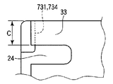
- FIG. 18A is an enlarged view showing a configuration of a spout portion of the refill container.
- FIG. 18B is a cross-sectional view schematically showing the configuration of the XVII-XVII cross section of the pouring outlet.
- FIG. 18C is a cross-sectional view schematically showing a state in which the area of the pouring outlet is maximized by an XVII-XVII cross section.
- the refill container 700 includes a laminated body 10, and includes a main body surface laminated body 2 and a main body back laminated body 3. Seal. Further, the refill container 700 is configured to bend the single laminate 10 with the sealant layer 12 inside to form the bent portion 6, the main body surface laminate 2, and the main body back laminate 3. The bent portion 6 and the spout seal portion 24 form an outflow path 33 for pouring the contents.
- the refill container 700 can form the spout 731 by separating the leading end of the outflow passage 33 along the planned opening line 734.
- the main body front surface laminate 2 and the main body back surface laminate 3 are sealed by the side seal portion 22 and the bottom seal portion 23 to form a bag shape.
- a filling opening for filling the contents is necessary, but is omitted in FIG.
- a filling opening can be provided in the bottom seal portion 23 or the side seal portion 22.
- the scheduled opening line 734 at the tip of the outflow passage 33 is a virtual line indicating the opening position, but in order to clarify the opening position, a print display or the like may be actually performed. Moreover, it can also be set as the half cut line provided in the outer surface of the main body surface laminated body 2 and / or the main body back surface laminated body 3. FIG. By doing so, it is possible to easily form the spout 31 by tearing the portion of the planned opening line 734 by hand.
- a method of forming with a blade and a method of forming by laser processing are generally used, but the method by laser processing is preferable because a uniform and stable cut can be formed.
- a V-shaped or U-shaped notch or incision line is provided in the spout seal portion corresponding to the planned opening line 734, or the tip end portion of the spout seal portion 24 is processed to have a wide width. Ease of operation is further improved.
- the spout 731 of the refill container 700 has a width of the spout 731 as C (mm) and an opening cross-sectional area of the spout 731 as D (mm 2 ). It is formed so as to satisfy the relationship of 1/10 ⁇ (C 2 / ⁇ ) (mm 2 ) ⁇ D (mm 2 ) ⁇ C 2 / ⁇ (mm 2 ).
- This relational expression shows that the opening cross-sectional area D (mm 2 ) of the spout is larger than 1/10 of C 2 / ⁇ (mm 2 ), which is the theoretical maximum value of the opening cross-sectional area. Show.
- the opening cross-sectional area B of the spout 731 is ensured widely. Moreover, it becomes easy to insert in the nozzle cap part of the container 51 main body used repeatedly. For this reason, the flow volume of the content at the time of refilling operation can also be ensured large. For this reason, the refill container 700 can be smoothly and quickly refilled.
- the dimension C in FIG. 18A is a numerical value measured in a state where the spout 731 is pressed flat. As shown in FIG. 18B, the actual cross section of the spout 731 is in a state of bulging horizontally due to the elasticity of the laminated body 10.
- the opening cross-sectional area of the spout 731 at this time is D (mm 2 ).
- C 2 / ⁇ is the opening cross-sectional area D of the spout 731 when the spout 731 is assumed to be a perfect circle, and this value is the maximum value of the cross-sectional area D of the spout 731. .
- a refill container 800 according to a ninth embodiment of the present invention will be described in detail with reference to FIGS. 14, 15A, 15B, 18A, 18B, and 18C.
- symbol is attached
- the refill container 800 of this embodiment has the main body surface laminate 2, the main body back laminate 3, and the bottom tape 4 in the same manner as the refill container 500, with the respective sealant layers facing each other and sealing the periphery. Become.
- the bottom tape 4 is bent at the bottom of the container so that the sealant layer is on the outside.
- One end of the bottom tape 4 forms the bottom seal portion 123 together with the main body surface laminate 2, and the other end forms the bottom seal portion 123 together with the main body back surface laminate 3 to constitute the bottom surface of the container.
- This type of packaging bag is referred to as a so-called standing pouch, and has a feature that a large-capacity container can be realized because the bottom surface widens greatly.
- the bent portion 6 is formed by bending one laminated body at the top with the sealant layer inside, and the bent portion 6 reaches the spout 731 together with the spout seal portion 24 and the punching portion 25.
- the outflow passage 33 of the contents is formed as a pour nozzle 832 protruding. That is, the refill container 800 has a configuration including a dispensing nozzle 832 having a spout 731 that is different from the dispensing nozzle 432 formed in the refill container 500 described above. For this reason, the pouring nozzle 832 can obtain the same effect as the above-described refill container 700 by the pouring port 731.
- FIG. 14 shows a state where the top opening 21 is formed by sealing the filling opening 41.
- a refill container 900 according to a tenth embodiment of the present invention will be described in detail with reference to FIGS. 6, 7, 8, 16, 16, 18A, 18B, and 18C.
- symbol is attached
- the refill container 900 has the same configuration as that of the refill container 600 and is provided with the above-described discharge nozzle 832 instead of the discharge nozzle 432 of the refill container 600. .
- the refill container 900 is provided with a handle 26 having a shape that fits in the punching portion 25 on the side opposite to the punching portion 25 of the spout seal portion 24 that forms the pouring nozzle 832.
- the outflow path 33 is formed as a protruding spout nozzle 832.
- the shape of the punching portion 25 an appropriate shape can be selected according to the structure around the stopper portion of the container that is repeatedly used.
- the laminated body 10 slit to a width approximately twice the width corresponding to the height of the container is folded at the top with the surface of the sealant layer 12 facing the opposite side.
- the main body surface laminate 2 and the main body back laminate 3 are obtained.
- the laminated body 10 is continuously supplied, and the bottom tape 4 folded in half so that the surface of the sealant layer 12 is on the outside is continuously supplied.
- the bottom tape 4 such as the side seal portion 22, the bottom seal portion 123, and the spout seal portion 24, it is punched into a container. .
- FIG. 7 are schematic views showing an example of a series of refilling operations using the refill container 900 according to the present embodiment.
- the refill container 900 according to the present embodiment is held, the tip of the dispensing nozzle 832 is cut, and the spout 731 is opened.
- the nozzle 52 of the container 51 that is emptied repeatedly is inserted into the spout 731.
- the container 51 to be repeatedly used is a plastic container provided with a nozzle cap 53 having a nozzle 52.
- the pouring nozzle 832 of the refill container 900 is securely inserted into the nozzle cap 53 of the container 51 to be used repeatedly.
- FIG. 9 when the entire arrangement is made so that the dispensing nozzle 832 is vertical while keeping the positional relationship between the container 51 and the refill container 900 to be repeatedly used constant, The contents are poured into the container 51 to be used repeatedly at once.
- the refill container 900 can secure a large-area spout without using a special plastic spout or the like. Since the size of can be freely designed according to the shape of the stopper of the container to be used repeatedly, it is extremely valuable as a dedicated refill container that can be quickly refilled.
- Example 8 As the main body surface laminate 2 and the main body back laminate 3, a laminate 10 having the following configuration was used.
- Example 9 A refill container 900 was produced in the same manner as in Example 8 except that the strength of the bending when forming the bent portion was adjusted so that the opening cross-sectional area D was 60 mm 2 . Filled with contents.
- Example 10 Similarly, a refill container was prepared and filled with the same contents as in Example 8, except that the opening cross-sectional area D was 40 mm 2 .
- Example 11 Similarly, a refill container 900 was produced in the same manner as in Example 8 except that the opening cross-sectional area D was 14 mm 2 and filled with the same contents.
- a refill container 900 was produced in the same manner as in Example 8 except that the opening cross-sectional area D was 10 mm 2, and the same contents were filled.
- Example 12 A refill container was prepared and filled with the same contents as in Example 8, except that the spout width C was 25 mm and the opening cross-sectional area D was 199 mm 2 .
- Example 13 A refill container was prepared in the same manner as in Example 12 except that the strength of bending when forming the bent portion was adjusted so that the opening cross-sectional area D was 120 mm 2. The product was filled.
- Example 14 Similarly, a refill container was prepared and filled with the same contents as in Example 12 except that the opening cross-sectional area D was 80 mm 2 .
- Example 15 Similarly, a refill container was prepared and filled with the same contents as in Example 12 except that the opening cross-sectional area D was 22 mm 2 .
- each of Examples 8 to 15 is 1/10 ⁇ (C 2 / ⁇ ) (mm 2 ) ⁇ D (mm 2 ) ⁇ C 2 / ⁇ (mm 2 ). The range that satisfies the relationship is shown. Note that when evaluating the quickness (pourability) of pouring, the refilling container 900 is tilted with the pouring outlet 731 open without using a dedicated container for repeated use for evaluation. The quickness of dispensing (pourability) was evaluated.
- the present embodiment provided with the dispensing nozzle 832 satisfying the relationship of 1/10 ⁇ (C 2 / ⁇ ) (mm 2 ) ⁇ D (mm 2 ) ⁇ C 2 / ⁇ (mm 2 )
- the refill container 900 which concerns on a form also has the favorable insertion property to a bottle, and has shown the preferable result in pouring property.
- the relationship of 1/10 ⁇ (C 2 / ⁇ ) (mm 2 ) ⁇ D (mm 2 ) ⁇ C 2 / ⁇ (mm 2 ) is not limited to the refill container 900 but also the refill containers 700 and 800. In order to satisfy, the same effects as the refill container 900 can be obtained for the refill containers 700 and 800 having the spout 731.
- a refill container 1000 according to an eleventh embodiment of the present invention will be described in detail with reference to FIGS. 19, 20, 21, and 22.
- symbol is attached
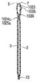
- FIG. 19 is a schematic diagram showing a configuration of a refill container 1000 according to the eleventh embodiment of the present invention.
- FIG. 20 is a cross-sectional view schematically showing the configuration of the refill container 1000 taken along the line XX-XX.
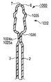
- FIG. 21 is an enlarged view for explaining the configuration of the convex emboss 1035 of the dispensing nozzle 1032 of the refill container 1000.
- FIG. 22 is an enlarged view for explaining the configuration of the concave emboss 1036 of the dispensing nozzle 1032 of the refill container 1000. It is.
- the refill container 1000 includes a laminate 10 having at least a base material 11 and a sealant layer 12. As shown in FIGS. 19 and 20, the refill container 1000 is formed by bending a single laminated body 10 with the sealant layer 12 inside, and bending portion 6, main body surface laminated body 2, and main body back surface laminated body 3. And the periphery is sealed.
- the bending part 6 forms a pouring nozzle 1032 for pouring the contents together with the pouring nozzle seal part 1024a and the punching part seal part 1025a.
- the tip of the dispensing nozzle 1032 is sealed by the dispensing nozzle tip seal portion 1024b.
- the dispensing nozzle 1032 forms the dispensing port 1031 by cutting along the planned opening line 1034.
- the laminated body 10 forming the dispensing nozzle 1032 is provided with a convex emboss 1035 having a strip shape or a streak shape that is convex outward.
- the convex emboss 1035 has an embossed center line 1035c in the range of 2 / 3E from the dispensing nozzle seal portion 1024a on the planned opening line 1034, where E is the length of the planned opening line 1034. Further, the convex emboss 1035 exists at least continuously from the expected opening line 1034 to the extension line 1025b of the punched portion seal portion 1025a.
- the bent portion 6 is formed by bending a single laminate 10 at the top with the sealant layer 12 inside.
- the bent portion 6 forms an outflow passage 1033 for contents to reach the spout 1031 together with the pouring nozzle seal portion 1024a and the punching portion seal portion 1025a provided at the lower portion of the bent portion 6. Due to the elastic action of the laminated body 10 to return in the bent portion 6, the cross section of the outflow path 1033 is always in a state where the upper part is swollen. For this reason, it becomes possible to ensure the cross-sectional area of the spout 1031 widely. As a result, the refill container 1000 can discharge a large amount of contents at a time.
- the convex emboss 1035 is an emboss provided in a convex shape on the outer side with respect to the laminated body 10, and the shape thereof is a strip shape or a streak shape.
- the band shape refers to a rectangular, trapezoidal, semicircular, or semi-cylindrical cross section, and the streak refers to a linear embossment having a triangular cross section.
- the convex emboss 1035 may be continuous even if it is not linear.
- the length of the convex emboss 1035 exists at least continuously from the expected opening line 1034 to the extension line 1025b of the punched portion seal portion 1025a.
- the extension line 1025b of the punched portion seal portion 1025a may be provided so as to greatly exceed.
- the angle ⁇ formed by the center line 1035c of the convex emboss 1035 and the ridgeline 7 of the bent portion 6 is more preferably 0 ° or more and 60 ° or less.
- the angle ⁇ is within this range, the effect of smoothing the opening of the spout 1031 is further enhanced.
- the main body surface laminate 2 and the main body back laminate 3 are sealed in the side seal portion 22 and the bottom seal portion 23 to form a bag shape.
- a filling opening for filling the contents is necessary, but is omitted in FIG.
- the bottom seal portion 23 or the side seal portion 22 can be provided with a filling opening.
- a part of the bent portion 6 can be cut open to form a filling opening.
- the bent portion 6 is disposed horizontally on the top of the refill container 1000, but may be disposed vertically on the side surface of the refill container 1000.
- the refill container 1000 is provided with a V-shaped or U-shaped notch or cutting line on the pouring nozzle seal portion 1024a and the pouring nozzle tip seal portion 1024b corresponding to the expected opening line 1034, or the pouring nozzle seal.
- the ease of opening is improved by processing the leading end portions of the portion 1024a and the dispensing nozzle tip seal portion 1024b to be wide and providing the opening knob 8.
- the expected opening line 1034 is a virtual line indicating the opening position, but in order to clarify the opening position, printing display or the like may be actually performed. Moreover, it is preferable that the expected opening line 1034 is a half-cut line provided continuously on the outer surface of the main body surface laminate 2 and the main body back laminate 3. By doing so, it is possible to easily form the spout 1031 by tearing the portion of the expected opening line 1034 by hand.
- a method of forming with a blade and a method of forming by laser processing are generally used, but the method by laser processing is preferable because a uniform and stable cut can be formed. As the type of laser, a carbon dioxide laser is more preferable.
- the planned opening line 1034 does not need to be perpendicular to the ridge line 7 of the bent portion, and may be oblique.
- the laminated body 10 used for the refill container 1000 As the laminated body 10 used for the refill container 1000 according to the present embodiment, a normal soft packaging bag similar to the above-described refill container 1,100,200,300,400,500,600,700,800,900.
- the laminate 10 used in the above can be used.
- FIG. 22 is an enlarged view of the pouring nozzle of the refill container 1000 according to the present embodiment, and is an explanatory view of the concave emboss 1036.
- a concave band-like or streak-like concave emboss 1036 is provided at a specific position at a specific angle between the convex emboss 1035 and the dispensing nozzle seal portion 1024a, the spout 1031 and the outflow path 1033 are provided. It is possible to secure a larger cross-sectional area.
- the dispensing nozzle 32 is not bent or detached from the container to be used repeatedly, and the effect that the refilling operation can be performed easily, quickly and surely becomes stable.
- the main function of the concave emboss 1036 is to improve that the vicinity of the spout nozzle seal portion 1024a of the spout 1031 is difficult to spread, but also has a function to enhance the effect of preventing the spout 1031 from being bent. .
- the concave emboss 1036 has a center line 1036c of the concave emboss in a range within 3 mm from the pouring nozzle seal portion 1024a on the planned opening line 1034.
- the concave emboss 1036 exists at least continuously from the planned opening line 1034 to the extension line 1025b of the punched portion seal portion 1025a.
- the concave emboss 1036 preferably has an angle of the concave emboss center line 1036c in a range from an angle parallel to the dispensing nozzle seal portion to an angle perpendicular to the ridge line 7 of the bent portion 6. In FIG. 22, the range of this angle is represented by ⁇ .
- the shape of the concave emboss 1036 is the same as that of the convex emboss 1035, and the shape thereof is a strip or a streak.
- the strip shape refers to a rectangular, trapezoidal, semicircular, or semi-cylindrical cross section
- the streak refers to a linear embossment having a triangular cross sectional shape.
- the concave emboss 1036 may be a curve instead of a straight line as long as it is continuous, or a curve along the dispensing nozzle seal portion 1024a.
- convex emboss 1035 and the concave emboss 1036 do not have to be strip-shaped or streak-shaped.
- a convex emboss 1035A and a concave emboss 1036A which are modifications of the convex emboss 1035 and the concave emboss 1036 used in the refill container 1000 according to the present embodiment, will be described.
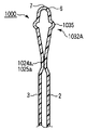
- FIG. 23 is an enlarged view showing a configuration of a dispensing nozzle 1032A, which is a modification of the dispensing nozzle 1032 of the refill container 1000 according to the present embodiment, and shows the configuration of the convex emboss 1035A and the concave emboss 1036A.
- the dispensing nozzle 1032A is formed with one streak-like embossing for each of the convex emboss 1035A and the concave emboss 1036A.
- even such a simple embossed shape can sufficiently exhibit its effect.
- such streak-like embossing is preferable from the viewpoint of preventing the paper from cracking.
- FIG. 24A is an enlarged cross-sectional view showing an example of the configuration of the pouring nozzle 1032 of the refill container 1000.
- FIG. 24B is an enlarged cross-sectional view showing an example of the configuration of the dispensing nozzle 1032 of the refill container 1000.
- FIG. 24C is an enlarged cross-sectional view illustrating an example of the configuration of the dispensing nozzle 1032A of the refill container 1000.
- FIG. 24D is an enlarged cross-sectional view showing an example of the configuration of the dispensing nozzle 1032A of the refill container 1000A.
- the pouring nozzle 1032 is provided with a belt-like convex emboss 1035 having a trapezoidal cross-sectional shape and a belt-like concave embossing 1036 having a trapezoidal cross-sectional shape. Yes.
- the pouring nozzle 1032 may have a configuration without the concave emboss 1036 as long as the cross-sectional area of the pouring outlet 1031 can be secured widely.
- a stripe-like convex emboss 1035A having a triangular cross section and a stripe-like concave emboss 10A having a triangular cross section are provided.
- the pouring nozzle 1032A may have a configuration without the concave emboss 1036A as long as the cross-sectional area of the pouring port 1031 can be secured widely.
- FIG. 25 is a schematic diagram showing a configuration of a refill container 1100 according to the twelfth embodiment of the present invention.
- FIG. 26A is a cross-sectional view schematically showing the configuration of the refill container 1100 in the section XXVI-XXVI.
- FIG. 26B is a cross-sectional view schematically showing the refill container 1100 with the refill container 1100 open, with the configuration of the refill container 1100 taken along the line XXVI-XXVI.
- the refill container 1100 includes a single laminate 10 having at least a base material 11 and a sealant layer 12, with the sealant layer 12 on the outside.
- the bottom tape 4 is bent to be inserted between the main body surface laminate 2 and the main body back laminate 3, and the periphery is sealed.
- the refill container 1100 has a standing pouch shape.
- the refill container 1100 has the bending part 6 similarly to the refill container 1000 mentioned above.
- the bending part 6 forms the pouring nozzle 1032 for pouring out the contents together with the pouring nozzle seal part 1024a and the punching part seal part 1025a.
- the refill container 1100 cannot be provided with a filling opening for filling the contents in the side seal portion, and therefore a part of the bent portion 6 is cut open to form a filling opening 1141.
- the filling opening 1141 is sealed to become a top seal portion 1121.
- the presence of the filling opening 1141 at the top of the refill container 1100 has the advantage of facilitating the filling operation of the contents.
- the refilling container 1100 having a standing pouch shape can easily be a large-capacity container because the bottom tape 4 spreads. Therefore, it is possible to make full use of the feature that the dispensing time in the refill container 1100 according to the present embodiment is short.
- the bent portion 6 is formed by bending a single laminate 10 at the top with the sealant layer 12 inside.
- the bent portion 6 forms an outflow passage 1033 for the contents reaching the spout 1031 together with the spout nozzle seal portion 1024a and the punched portion seal portion 1025a.
- FIG. 27 is a schematic diagram showing a configuration of a refill container 1200 according to the thirteenth embodiment of the present invention.
- This refill container 1200 has a configuration in which a handle 1226 having a shape that fits in the punching portion 1225 is provided on the side opposite to the punching portion 1225 of the pouring nozzle seal portion 1024a that forms the pouring nozzle 1032.
- the outflow passage 1033 is formed as a protruding dispensing nozzle 1032.
- the shape of the punching portion 1225 an appropriate shape can be selected according to the structure around the stopper portion of the container 51 that is repeatedly used.
- the laminated body 10 slit to a width approximately twice the width corresponding to the height of the refill container 1200 is placed on the top with the surface of the sealant layer 12 facing inside.
- the main body front surface laminate 2 and the main body back surface laminate 3 are formed by bending and facing each other. Next, this is continuously supplied, and in the meantime, the bottom tape 4 folded in half so that the surface of the sealant layer 12 is on the outside is continuously supplied. After the supply, after performing necessary sealing, it is punched out to make a refill container 1200.
- the punching portion 1225 is a portion that is originally discarded. However, as shown in FIG. 27, if the handle 1226 is shaped so as to fit in the punching portion 1225 of the adjacent refill container 1200, the handle 1226 can be added without any particular increase in material. Since the handle 1226 exists, the refilling operation can be performed with the handle 1226. For this reason, the refilling operation can be performed more safely and easily using the refill container 1200.
- the refill container 1200 has a filling opening 1241 for cutting out a part of the bent portion 6 and filling the contents.
- the punched portion 1225 and the handle 1226 exist in the side seal portion 22, it is difficult to provide the filling opening 1241 having a sufficient width in addition to the bent portion 6. Therefore, it is preferable to provide the filling opening 1241 at the bent portion 6.
- FIG. 6 to 8 are schematic diagrams showing an example of a series of refilling operations using the refill container 1200 according to the embodiment of the present invention.
- the refill container 1200 according to the present embodiment is held, the tip of the dispensing nozzle 1032 is cut, and the spout 1031 is opened.
- the nozzle 52 of the container 51 that is emptied repeatedly is inserted into the spout 1031.
- the container 51 to be repeatedly used is a plastic container provided with a nozzle cap 53 having a nozzle 52.
- the pouring nozzle 1032 of the refill container 1200 is reliably inserted into the nozzle cap 53 of the container 51 to be used repeatedly.
- the entire arrangement is made so that the dispensing nozzle 1032 is vertical while keeping the positional relationship between the container 51 and the refill container 1200 to be repeatedly used constant, The contents are poured into the container 51 to be used repeatedly at once.
- the refill container 1200 can secure the spout 1031 having a large area without using a special plastic spigot or the like.
- the size of the spout 1031 can be freely designed according to the shape of the stopper of the container 51 to be used repeatedly, so that it is extremely valuable as a dedicated refill container that can be quickly refilled. Is high.
- Example 16 As the main body surface laminate 2 and the main body back laminate 3, a laminate 10 having the following configuration was used.
- the filling opening 1141 As the filling opening 1141, a part of the bent portion 6 was cut to form a filling opening 1141.
- the scheduled opening line 1034 that should become the spout 1031 at the tip of the spout nozzle 1032 was a half-cut line by laser processing.
- the refill container 1200 thus obtained was filled with 900 g of a liquid detergent, and the filling opening 1141 was heat-sealed to obtain a test specimen for evaluation.
- Example 17 An evaluation container was prepared in the same manner as in Example 16 except that the dispensing nozzle 1032 was also provided with a concave emboss 1036 in addition to the convex emboss 1035, and was filled with the same contents.
- the concave emboss 1036 has a trapezoidal cross section, a height of 1 mm, a length of 30 mm, and an angle ⁇ of 35 °.
- the tip of the pouring nozzle 1032 of the refill container 1200 which is each of the above-mentioned evaluation test bodies, was cut by hand along the planned opening line 1034, and the time required for pouring the contents was evaluated.
- the results of these experiments are shown in Table 3 and FIG.
- the pouring time in Table 3 is the time required for pouring out 95% of the internal volume.
- the dispensing time can be shortened by providing the protruding nozzle 1032 with the convex emboss 1035. Further, it can be seen that when the concave embossing 1036 is provided in the dispensing nozzle 1032, it is further shortened.
- the dispensing nozzle 1032 has not only the refill container 1200 but also the refill containers 1000 and 1100, the same effect as the refill container 1200 can be obtained for the refill containers 1000 and 1100.
- the refill container according to the present invention is a refill container comprising a laminate having at least a base material and a sealant layer, and has a main body surface laminate and a main body back laminate, with each sealant layer facing each other, Since the periphery is sealed, unlike a plastic bottle or a container using a plastic spigot, it can be manufactured only from the flexible packaging laminate, so that it can be manufactured at low cost.
- a single laminate is folded gently at the top with the sealant layer inside, to form a folded portion, the main body surface laminate, and the main body back laminate.
- the bent portion together with the spout seal portion provided at the lower portion of the bent portion, forms the outflow passage of the contents reaching the spout in a horizontally long shape and forms a pouring nozzle (outflow passage) for pouring out the contents. .
- the spout can be formed easily and reliably.
- the tip of the dispensing nozzle is cut along the planned opening line to form a spout, the length of the planned opening line is A (mm), and the opening width of the spout is B (mm) In this case, the relationship of A-4 (mm) ⁇ B (mm) ⁇ A ⁇ 0.5 (mm) is satisfied.
- the opening width is wide enough for the length of the planned opening line, and it can be easily inserted into the nozzle cap of the container body that is used repeatedly.
- a quick refilling operation can be stably performed.
- the tip of the outflow passage is cut along the planned opening line to form a spout, the width of the spout is A (mm), and the opening cross-sectional area of the spout is B (mm 2 ). Then, the relationship of 1/10 ⁇ (A 2 / ⁇ ) (mm 2 ) ⁇ B (mm 2 ) ⁇ A 2 / ⁇ (mm 2 ) is satisfied. Thereby, a wide opening cross-sectional area is ensured, and it becomes easy to insert into the nozzle cap of the container body to be used repeatedly. In addition, since the flow rate at the time of dispensing can be secured, a quick refilling operation can be stably performed.
- the refill container has a convex cross section of the spout and the outflow passage by providing a convex emboss in the shape of a strip or streak on the outer side at a specific position of the laminate forming the spout nozzle. It becomes possible to do. Further, the dispensing nozzle is not bent or detached from the container to be used repeatedly.
- the refill container has a main body surface laminate, a main body back laminate, and a bottom tape, each sealant layer is opposed to each other, and the periphery is sealed.
- the bottom tape is formed by bending a single laminate having at least a base material and a sealant layer at the lower part of the container with the sealant layer facing outward.
- the bottom tape is inserted between the main body surface laminate and the main body back surface laminate to seal the periphery, so that one end of the bottom tape is the main body surface laminate, and the other end is the main body back surface laminate and the bottom seal part.
- a so-called standing pouch is formed by forming the bottom of the container. As described above, when the refill container has a standing pouch shape, it can be a self-supporting large-capacity refill container, and the effects of the present refill container can be fully utilized.
- the refilling operation can be performed with the grip. . For this reason, the refilling operation can be performed more safely and easily.
- the handle since the handle has a shape that fits in the punched portion, the laminate is not wasted when manufactured by punching from a continuous laminate.
- the spout can be easily opened by tearing by hand.
- the planned opening line is a half-cut line provided on the outer surface of the main body surface laminate and / or the main body back laminate, the spout can be easily opened by tearing by hand.
- the nozzle of the container to be used repeatedly having a nozzle cap when the nozzle of the container to be used repeatedly having a nozzle cap can be inserted into the pouring nozzle, the nozzle of the container to be used repeatedly is inserted into the pouring nozzle held horizontally. Tilt the container so that the dispensing nozzle is vertical. Thereby, it becomes a refill container which enabled quick refill, and the effect of the present invention is exhibited to the maximum.
- the spout is naturally opened due to the presence of the bent portion obtained by gently bending one laminated body, so that it is easy to insert the nozzle of the target container.
- the size of the spout according to the nozzle it is possible to make the spout perfectly fit the nozzle. For this reason, after inserting the nozzle of the container to be repeatedly used into the pouring nozzle held horizontally, the refilling operation can be performed quickly by tilting so that the pouring nozzle becomes vertical.
- Outlet 32, 232, 332, 432, 1032, 1032A ... Nozzle 33, 1033 ... Outflow channel, 34, 334, 434, 734, 1034 ... Expected opening line, 41, 141, 1141, 1241 ... Filling Opening 51, container for repeated use, 52 ... nozzle, 53 ... nozzle cap, 104 ... bottom tape, 1024a ... pouring nozzle seal part, 1024b ... pouring nozzle tip seal part, 1025a ... punching part seal part, 1025b ... extension line, 1035, 1035A ... convex emboss, 1036, 1036A ... concave emboss.
Landscapes
- Engineering & Computer Science (AREA)
- Mechanical Engineering (AREA)
- Bag Frames (AREA)
Abstract
Description
図6に示したように、本実施の形態の詰替え容器200を保持し、注出ノズル32の先端をカットして注出口31を開く。この注出口31に空になった繰り返し使用する容器51のノズル52を挿入する。この図では、繰り返し使用する容器51は、ノズル52を有するノズルキャップ53を備えたプラスチック容器である。
本体表面積層体2および本体裏面積層体3として以下の構成からなる積層体10を使用した。
<本体表面積層体2及び本体裏面積層体3に用いる積層体10の構成>
PET(東レ社製P60、12μm)/印刷層/接着剤層(東洋モートン社製TM272、3g/m2(dry))/ONY(ユニチカ社製ONMB、15μm)/接着剤層(同上)/LLDPE(東セロ社製TUX-FCS、150μm)
底テープ4として以下の構成からなる積層体10を使用した。
<底テープ4に用いる積層体10の構成>
ONY(ユニチカ社製ONM、25μm)/LLDPE(同上、120μm)
上記の積層体10を用いて、詰替え容器300として、図5に示す形状のスタンディングパウチを作製した。なお充填用開口部141としては、折り曲げ部6の一部をカットし、充填用開口部141とした。また注出ノズル332先端部の注出口31となるべき部分にレーザー加工によるハーフカット線334を設け、開口予定部とした。こうして得られた詰替え容器300に家庭用液体洗剤を充填し、充填用開口部141をヒートシールして詰替え用洗剤とした。
本体表面積層体2および本体裏面積層体3として以下の構成からなる積層体10を使用した。
PET(東レ社製P60、12μm)/印刷層/接着剤層(東洋モートン社製TM272、3g/m2(dry))/ONY(ユニチカ社製ONMB、15μm)/接着剤層(同上)/LLDPE(東セロ社製TUX-FCS、150μm)
底テープとして以下の構成からなる積層体10を使用した。
ONY(ユニチカ社製ONM、25μm)/LLDPE(同上、120μm)
上記の積層体10を用いて、図16に示した形状のスタンディングパウチを作製した。なお充填用開口部141としては、折り曲げ部6の一部をカットし、充填用開口部141とした。また注出ノズル432先端部の注出口31となるべき開封予定線334をレーザー加工によるハーフカット線とした。こうして得られた詰替え容器に家庭用液体洗剤を充填し、充填用開口部をヒートシールして詰替え用洗剤とした。この時、図12Aに示した開封予定線の長さAを18mmとした。また開口部幅Bを14mmとした。
開封予定線の長さAを18mmとし、開口部幅Bを15mmとした以外は、実施例2と同様にして、詰替え容器を作製し、同様の内容物を充填した。
開封予定線の長さAを18mmとし、開口部幅Bを17.5mmとした以外は、実施例2と同様にして、詰替え容器を作製し、同様の内容物を充填した。
開封予定線の長さAを30mmとし、開口部幅Bを26mmとした以外は、実施例2と同様にして、詰替え容器を作製し、同様の内容物を充填した。
開封予定線の長さAを30mmとし、開口部幅Bを27mmとした以外は、実施例2と同様にして、詰替え容器を作製し、同様の内容物を充填した。
開封予定線の長さAを30mmとし、開口部幅Bを29.5mmとした以外は、実施例2と同様にして、詰替え容器を作製し、同様の内容物を充填した。
開封予定線の長さAを18mmとし、開口部幅Bを13mmとした以外は、実施例2と同様にして、詰替え容器を作製し、同様の内容物を充填した。
開封予定線の長さAを18mmとし、開口部幅Bを17.7mmとした以外は、実施例2と同様にして、詰替え容器を作製し、同様の内容物を充填した。
開封予定線の長さAを30mmとし、開口部幅Bを25mmとした以外は、実施例2と同様にして、詰替え容器を作製し、同様の内容物を充填した。
開封予定線の長さAを30mmとし、開口部幅Bを29.7mmとした以外は、実施例2と同様にして、詰替え容器を作製し、同様の内容物を充填した。
注出ノズル482の構造を図13Aに示したような従来の形状とし、開封予定線の長さAを18mmとし、開口部幅Bを12mmとした以外は、実施例2と同様にして、詰替え容器を作製し、同様の内容物を充填した。なお注出口483の開口部は、注出ノズル482の中央に配置した。
注出ノズル482の構造を図13Aに示したような従来の形状とし、開封予定線の長さAを30mmとし、開口部幅Bを24mmとした以外は、実施例2と同様にして、詰替え容器を作製し、同様の内容物を充填した。

本体表面積層体2および本体裏面積層体3として以下の構成からなる積層体10を使用した。
PET(東レ社製P60、12μm)/印刷層/接着剤層(東洋モートン社製TM272、3g/m2(dry))/ONY(ユニチカ社製ONMB、15μm)/接着剤層(同上)/LLDPE(東セロ社製TUX-FCS、150μm)
底テープとして以下の構成からなる積層体10を使用した。
ONY(ユニチカ社製ONM、25μm)/LLDPE(同上、120μm)
上記の積層体10を用いて、図16に示した形状のスタンディングパウチを作製した。なお充填用開口部141としては、折り曲げ部6の一部をカットし、充填用開口部141とした。また注出ノズル832先端部の注出口731となるべき開封予定線334をレーザー加工によるハーフカット線とした。こうして得られた詰替え容器に家庭用液体洗剤を充填し、充填用開口部をヒートシールして詰替え用洗剤とした。この時、図18Aに示した注出口の幅Cを20mmとした。また開口部断面積Dを127mm2とした。
折り曲げ部を形成する際の折り曲げの強さを調節して、開口部断面積Dが60mm2となるようにした以外は、実施例8と同様にして、詰替え容器900を作製し、同様の内容物を充填した。
同様にして開口部断面積Dが40mm2となるようにした以外は、実施例8と同様にして、詰替え容器を作製し、同様の内容物を充填した。
同様にして開口部断面積Dが14mm2となるようにした以外は、実施例8と同様にして、詰替え容器900を作製し、同様の内容物を充填した。
同様にして開口部断面積Dが10mm2となるようにした以外は、実施例8と同様にして、詰替え容器900を作製し、同様の内容物を充填した。
注出口の幅Cを25mmとし、開口部断面積Dを199mm2とした以外は、実施例8と同様にして、詰替え容器を作製し、同様の内容物を充填した。
折り曲げ部を形成する際の折り曲げの強さを調節して、開口部断面積Dが120mm2となるようにした以外は、実施例12と同様にして、詰替え容器を作製し、同様の内容物を充填した。
同様にして開口部断面積Dが80mm2となるようにした以外は、実施例12と同様にして、詰替え容器を作製し、同様の内容物を充填した。
同様にして開口部断面積Dが22mm2となるようにした以外は、実施例12と同様にして、詰替え容器を作製し、同様の内容物を充填した。
同様にして開口部断面積Dが18mm2となるようにした以外は、実施例12と同様にして、詰替え容器を作製し、同様の内容物を充填した。
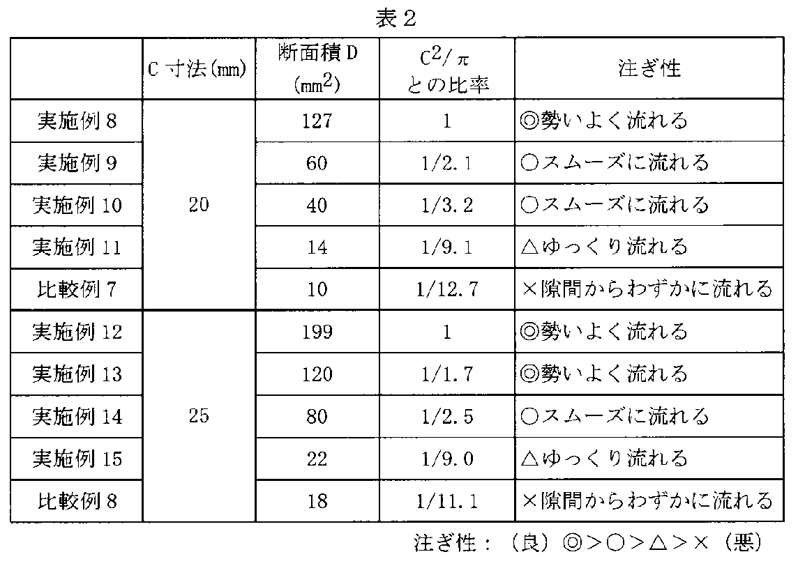
図22は、本実施の形態に係る詰替え容器1000の注出ノズルの拡大図であり、凹エンボス1036の説明図である。凸エンボス1035と注出ノズルシール部1024aの間に、外側に凹の、帯状または筋状の凹エンボス1036を、特定の角度をもって特定の位置に設けた場合においては、注出口1031および流出路1033の断面積をさらに大きく確保することが可能となる。また、注出ノズル32が折れ曲がったり、繰り返し使用する容器から外れたりすることがなくなり、詰め替え操作が容易かつ迅速で確実にできる効果が安定したものとなる。凹エンボス1036の主な働きは、注出口1031の注出ノズルシール部1024a付近が広がりにくいことを改善しようとするものであるが、注出口1031の折れ曲がりを防止する効果を高める働きも持っている。
この詰替え容器1200は、注出ノズル1032を形成する注出ノズルシール部1024aの抜き加工部1225と反対の側に、抜き加工部1225に納まる形状の把手1226を設ける構成である。注出ノズルシール部1024aに抜き加工部1225を形成することにより、流出路1033は、突出した注出ノズル1032として形成されることになる。抜き加工部1225の形状は、繰り返し使用する容器51の口栓部周辺の構造に応じて、適当な形状を選択することができる。
本体表面積層体2および本体裏面積層体3として以下の構成からなる積層体10を使用した。
PET(東レ社製P60、12μm)/印刷層/接着剤層(東洋モートン社製TM272、3g/m2(dry))/ONY(ユニチカ社製ONMB、15μm)/接着剤層(同上)/LLDPE(東セロ社製TUX-FCS、150μm)
底テープとして以下の構成からなる積層体を使用した。
ONY(ユニチカ社製ONM、25μm)/LLDPE(同上、120μm)
上記の積層体10を用いて、図27に示した形状のスタンディングパウチを作製した。パウチサイズは、巾150mm、高さ272mmとした。注出ノズル1032のエンボスは、凸エンボス1035のみとし、凹エンボス1036は施さなかった。凸エンボス1035は、断面形状が台形で、高さ1mm、長さ40mm、角度θを50°とした。
注出ノズル1032に凸エンボス1035に加えて凹エンボス1036も施した以外は、実施例16と同様にして評価用容器を作成し、同様の内容物を充填した。凹エンボス1036は、断面形状が台形で、高さ1mm、長さ30mm、角度δを35°とした。
注出ノズルにエンボスを施さない以外は、実施例1と同様にして評価用容器を作成し、同様の内容物を充填した。
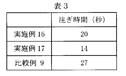
Claims (24)
- 基材とシーラント層を少なくとも有する積層体からなる詰替え容器であって、
1枚の前記積層体を、前記シーラント層を内側にして天部で折り曲げて形成された折り曲げ部と、
前記折り曲げた前記積層体により形成された本体表面積層体と、
前記折り曲げた前記積層体により形成された前記本体裏面積層体と、を有し、
前記本体表面積層体及び前記本体裏面積層体は、それらシーラント層同士を対向させ、周囲をシールしてなり、
前記折り曲げ部は、その下部に注出口シール部が設けられ、前記注出口シール部と共に、注出口に至る内容物の流出路を形成することを特徴とする詰替え容器。 - 前記積層体で形成され、前記シーラント層を外側にして折り曲げて前記本体表面積層体と本体裏面積層体の間に挿入される底テープをさらに備え、
前記本体表面積層体、前記本体裏面積層体及び前記底テープの周縁をシールすることで、前記底テープの一端が前記本体表面フィルムと、前記底テープの他端が前記本体裏面フィルムとそれぞれボトムシール部を形成して底面を構成することを特徴とする請求項1に記載の詰替え容器。 - 前記注出口シール部に設けられた抜き加工部をさらに有し、
前記抜き加工部は、突出した注出ノズルとして、前記流出路を形成することを特徴とする請求項1または請求項2に記載の詰替え容器。 - 前記注出ノズルを形成した側と反対の側に設けられ、前記抜き加工部に納まる形状の把手をさらに備えることを特徴とする請求項3に記載の詰替え容器。
- 前記注出口となるべき部分の本体表面積層体および本体裏面積層体の外側面にハーフカット線を設けたことを特徴とする請求項1から請求項4のいずれかに記載の詰替え容器。
- 前記折り曲げ部は、その一部を切り開くことで形成された内容物の充填用開口部を備えることを特徴とする請求項1から請求項5のいずれかに記載の詰替え容器。
- 基材とシーラント層を少なくとも有する積層体からなる詰替え容器であって、
1枚の前記積層体を、前記シーラント層を内側にして折り曲げて形成された折り曲げ部と、
前記折り曲げた前記積層体により形成された本体表面積層体と、
前記折り曲げた前記積層体により形成された本体裏面積層体と、を有し、
前記本体表面積層体及び前記本体裏面積層体は、それらシーラント層同士を対向させ、周囲をシールしてなり、
前記折り曲げ部は、その下部に注出口シール部が設けられ、前記注出口シール部と共に、内容物を注ぎ出すための注出ノズルを形成しており、
前記注出ノズルの先端は、その先端に開封予定線を有し、この開封予定線に沿って切り離すことにより注出口を形成し、該開封予定線長をA(mm)とし、前記注出口の開口部幅をB(mm)としたときに、
A-4(mm)≦B(mm)≦A-0.5(mm)
の関係を満たすことを特徴とする詰替え容器。 - 前記積層体で形成され、前記シーラント層を外側にして折り曲げて前記本体表面積層体と本体裏面積層体の間に挿入される底テープをさらに備え、
前記本体表面積層体、前記本体裏面積層体及び前記底テープの周縁をシールすることで、前記底テープの一端が前記本体表面フィルムと、前記底テープの他端が前記本体裏面フィルムとそれぞれボトムシール部を形成して底面を構成することを特徴とする請求項7に記載の詰替え容器。 - 前記注出口シール部に設けられた抜き加工部と、
前記注出ノズルを形成する注出口シール部の前記抜き加工部と反対の側に設けられ、該抜き加工部に納まる形状の把手と、
をさらに備えることを特徴とする請求項7または請求項8に記載の詰替え容器。 - 前記開封予定線は、本体表面積層体および/または本体裏面積層体の外側面に設けたハーフカット線であることを特徴とする請求項7から請求項9のいずれかに記載の詰替え容器。
- 前記折り曲げ部は、その一部を切り開くことで形成された、内容物の充填用開口部を備えることを特徴とする請求項7から請求項10のいずれかに記載の詰替え容器。
- 基材とシーラント層を少なくとも有する積層体からなる詰替え容器であって、
1枚の前記積層体を、前記シーラント層を内側にして折り曲げて形成された折り曲げ部と、
前記折り曲げた前記積層体により形成された本体表面積層体と、
前記折り曲げた前記積層体により形成された本体裏面積層体と、を有し、
前記本体表面積層体及び前記本体裏面積層体は、それらシーラント層同士を対向させ、周囲をシールしてなり、
前記折り曲げ部は、その下部に注出口シール部が設けられ、前記注出口シール部と共に、内容物を注ぎ出すための注出ノズルを形成しており、
前記注出ノズルの先端は、その先端に開封予定線を有し、この開封予定線に沿って切り離すことにより注出口を形成し、該注出口の幅をC(mm)とし、注出口の開口部断面積をD(mm2)としたときに、
1/10×(C2/π)(mm2)≦D(mm2)≦C2/π(mm2)
の関係を満たすことを特徴とする詰替え容器。 - 前記積層体で形成され、前記シーラント層を外側にして折り曲げて前記本体表面積層体と本体裏面積層体の間に挿入される底テープをさらに備え、
前記本体表面積層体、前記本体裏面積層体及び前記底テープの周縁をシールすることで、前記底テープの一端が前記本体表面フィルムと、前記底テープの他端が前記本体裏面フィルムとそれぞれボトムシール部を形成して底面を構成することを特徴とする請求項12に記載の詰替え容器。 - 前記注出口シール部に設けられた抜き加工部をさらに有し、
前記抜き加工部は、突出した注出ノズルとして、前記流出路を形成することを特徴とする請求項12または請求項13に記載の詰替え容器。 - 前記注出ノズルを形成する注出口シール部の抜き加工部と反対の側に設けられ、前記抜き加工部に納まる形状の把手をさらに備えることを特徴とする請求項12から請求項14のいずれかに記載の詰替え容器。
- 前記開封予定線は、本体表面積層体および/または本体裏面積層体の外側面に設けたハーフカット線であることを特徴とする請求項12から請求項15のいずれかに記載の詰替え容器。
- 前記折り曲げ部は、その一部を切り開くことで形成された内容物の充填用開口部を備えることを特徴とする請求項12から請求項16のいずれかに記載の詰替え容器。
- 基材とシーラント層を少なくとも有する積層体からなる詰替え容器であって、
1枚の前記積層体を、前記シーラント層を内側にして折り曲げて形成された折り曲げ部と、
前記折り曲げた前記積層体により形成された本体表面積層体と、
前記折り曲げた前記積層体により形成された本体裏面積層体と、を有し、
前記本体表面積層体及び前記本体裏面積層体は、それらシーラント層同士を対向させ、周囲をシールしてなり、
前記折り曲げ部は、その下部に注出口シール部が設けられ、前記注出口シール部と共に、内容物を注ぎ出すための注出ノズルを形成しており、
前記注出ノズルの先端は、注出ノズル先端シール部によってシールされており、開封予定線に沿って切り離すことにより注出口を形成し、
前記注出ノズルを形成する前記積層体は、外側に凸の、帯状または筋状の凸エンボスが設けられており、
前記凸エンボスは、前記開封予定線の長さをEとしたとき、前記開封予定線上の前記注出ノズルシール部からEの3分の2の範囲にその中心が存在し、前記開封予定線から前記抜き加工部シール部の延長線上までは少なくとも連続して存在している
ことを特徴とする詰替え容器。 - 前記積層体で形成され、前記シーラント層を外側にして折り曲げて前記本体表面積層体と本体裏面積層体の間に挿入される底テープをさらに備え、
前記本体表面積層体、前記本体裏面積層体及び前記底テープの周縁をシールすることで、その形状をスタンディングパウチ形状とすることを特徴とする請求項18に記載の詰替え容器。 - 前記折り曲げ部の稜線と前記凸エンボスの中心線のなす角度は、0°以上60°以下であることを特徴とする請求項18又は請求項19に記載の詰替え容器。
- 前記積層体の、前記凸エンボスと前記注出ノズルシール部の間に設けられ、外側に凹の、帯状または筋状の凹エンボスをさらに備え、
前記凹エンボスは、前記開封予定線上の前記注出ノズルシール部から3mm以内の範囲にその中心が存在し、前記開封予定線から前記抜き加工部シール部の延長線上までは少なくとも連続して存在しており、その角度は前記注出ノズルシール部に平行な角度から、前記折り曲げ部の稜線に垂直な角度までの範囲内である
ことを特徴とする請求項18から請求項20のいずれかに記載の詰替え容器。 - 前記開封予定線上に、ハーフカット線が施されていることを特徴とする請求項18から請求項21のいずれかに記載の詰替え容器。
- 前記注出ノズルを形成する前記注出口シール部の抜き加工部と反対の側に設けられ、該抜き加工部に納まる形状の把手をさらに備えることを特徴とする請求項18から請求項22のいずれかに記載の詰替え容器。
- 前記折り曲げ部は、その一部を切り開くことで形成された、内容物の充填用開口部を備えることを特徴とする請求項18から請求項23のいずれかに記載の詰替え容器。
Priority Applications (4)
| Application Number | Priority Date | Filing Date | Title |
|---|---|---|---|
| CN2010800267737A CN102459017A (zh) | 2009-06-19 | 2010-06-18 | 再填充容器 |
| JP2011519859A JP5673529B2 (ja) | 2009-06-19 | 2010-06-18 | 詰替え容器 |
| SG2011094109A SG176917A1 (en) | 2009-06-19 | 2010-06-18 | Refill container |
| KR1020117030119A KR101700988B1 (ko) | 2009-06-19 | 2010-06-18 | 리필 용기 |
Applications Claiming Priority (2)
| Application Number | Priority Date | Filing Date | Title |
|---|---|---|---|
| JP2009146137 | 2009-06-19 | ||
| JP2009-146137 | 2009-06-19 |
Publications (1)
| Publication Number | Publication Date |
|---|---|
| WO2010147212A1 true WO2010147212A1 (ja) | 2010-12-23 |
Family
ID=43356527
Family Applications (1)
| Application Number | Title | Priority Date | Filing Date |
|---|---|---|---|
| PCT/JP2010/060373 Ceased WO2010147212A1 (ja) | 2009-06-19 | 2010-06-18 | 詰替え容器 |
Country Status (6)
| Country | Link |
|---|---|
| JP (2) | JP5702056B2 (ja) |
| KR (1) | KR101700988B1 (ja) |
| CN (1) | CN102459017A (ja) |
| SG (1) | SG176917A1 (ja) |
| TW (1) | TWI523799B (ja) |
| WO (1) | WO2010147212A1 (ja) |
Cited By (4)
| Publication number | Priority date | Publication date | Assignee | Title |
|---|---|---|---|---|
| JP2012246010A (ja) * | 2011-05-27 | 2012-12-13 | Toppan Printing Co Ltd | 詰替え容器 |
| GB2589816A (en) * | 2019-06-13 | 2021-06-16 | Peter Hadley Stuart | Packaging for household liquids |
| JP2023080976A (ja) * | 2021-11-30 | 2023-06-09 | 花王株式会社 | 容器 |
| WO2023118070A1 (en) * | 2021-12-21 | 2023-06-29 | Société des Produits Nestlé S.A. | Flexible packaging for a liquid and method of manufacturing such a packaging |
Families Citing this family (2)
| Publication number | Priority date | Publication date | Assignee | Title |
|---|---|---|---|---|
| CN104684819B (zh) * | 2012-10-03 | 2017-08-22 | 凸版印刷株式会社 | 替换装容器 |
| EP3753859A4 (en) * | 2018-10-04 | 2021-04-07 | Kao Corporation | CONTAINER |
Citations (3)
| Publication number | Priority date | Publication date | Assignee | Title |
|---|---|---|---|---|
| JP2004168333A (ja) * | 2002-11-18 | 2004-06-17 | Toppan Printing Co Ltd | ノズル付き液体収納容器 |
| JP2007507399A (ja) * | 2003-10-02 | 2007-03-29 | エコ、レーン、リサーチ、アンド、デベロップメント、アクティーゼルスカブ | 容器用ブランク及び容器用ブランクから作られる容器 |
| JP2008018991A (ja) * | 2006-07-14 | 2008-01-31 | Toppan Printing Co Ltd | 軟質包装袋の注出口 |
Family Cites Families (6)
| Publication number | Priority date | Publication date | Assignee | Title |
|---|---|---|---|---|
| US4978232A (en) * | 1990-02-12 | 1990-12-18 | Colgate-Palmolive Co. | Flexible pouch with folded spout |
| JP3252222B2 (ja) | 1990-08-31 | 2002-02-04 | コニカ株式会社 | 自動繰出し装着型写真フィルムカートリッジ |
| EP0515896B1 (de) | 1991-05-16 | 1996-09-11 | Cellpack Ag | Beutel |
| JPH11236053A (ja) | 1998-02-20 | 1999-08-31 | Kanebo Ltd | 詰め替え用袋 |
| JP2004018991A (ja) * | 2002-06-20 | 2004-01-22 | Jfe Steel Kk | 電気めっきにおける金属イオンの供給装置 |
| JP4352671B2 (ja) | 2002-09-06 | 2009-10-28 | 東洋製罐株式会社 | 手放し詰め替え容器 |
-
2009
- 2009-08-07 JP JP2009184459A patent/JP5702056B2/ja not_active Expired - Fee Related
-
2010
- 2010-06-18 WO PCT/JP2010/060373 patent/WO2010147212A1/ja not_active Ceased
- 2010-06-18 KR KR1020117030119A patent/KR101700988B1/ko not_active Expired - Fee Related
- 2010-06-18 JP JP2011519859A patent/JP5673529B2/ja active Active
- 2010-06-18 TW TW099119790A patent/TWI523799B/zh not_active IP Right Cessation
- 2010-06-18 SG SG2011094109A patent/SG176917A1/en unknown
- 2010-06-18 CN CN2010800267737A patent/CN102459017A/zh active Pending
Patent Citations (3)
| Publication number | Priority date | Publication date | Assignee | Title |
|---|---|---|---|---|
| JP2004168333A (ja) * | 2002-11-18 | 2004-06-17 | Toppan Printing Co Ltd | ノズル付き液体収納容器 |
| JP2007507399A (ja) * | 2003-10-02 | 2007-03-29 | エコ、レーン、リサーチ、アンド、デベロップメント、アクティーゼルスカブ | 容器用ブランク及び容器用ブランクから作られる容器 |
| JP2008018991A (ja) * | 2006-07-14 | 2008-01-31 | Toppan Printing Co Ltd | 軟質包装袋の注出口 |
Cited By (5)
| Publication number | Priority date | Publication date | Assignee | Title |
|---|---|---|---|---|
| JP2012246010A (ja) * | 2011-05-27 | 2012-12-13 | Toppan Printing Co Ltd | 詰替え容器 |
| GB2589816A (en) * | 2019-06-13 | 2021-06-16 | Peter Hadley Stuart | Packaging for household liquids |
| GB2589816B (en) * | 2019-06-13 | 2022-04-20 | Peter Hadley Stuart | Packaging for household liquids |
| JP2023080976A (ja) * | 2021-11-30 | 2023-06-09 | 花王株式会社 | 容器 |
| WO2023118070A1 (en) * | 2021-12-21 | 2023-06-29 | Société des Produits Nestlé S.A. | Flexible packaging for a liquid and method of manufacturing such a packaging |
Also Published As
| Publication number | Publication date |
|---|---|
| CN102459017A (zh) | 2012-05-16 |
| JP2011020735A (ja) | 2011-02-03 |
| SG176917A1 (en) | 2012-01-30 |
| JP5673529B2 (ja) | 2015-02-18 |
| KR101700988B1 (ko) | 2017-01-31 |
| JPWO2010147212A1 (ja) | 2012-12-06 |
| KR20120028930A (ko) | 2012-03-23 |
| TWI523799B (zh) | 2016-03-01 |
| JP5702056B2 (ja) | 2015-04-15 |
| TW201103826A (en) | 2011-02-01 |
Similar Documents
| Publication | Publication Date | Title |
|---|---|---|
| JP5673529B2 (ja) | 詰替え容器 | |
| JP6516027B2 (ja) | 詰替え容器 | |
| JP5699458B2 (ja) | 詰替え容器 | |
| JP5573245B2 (ja) | 詰替え容器 | |
| JP2011255946A (ja) | 詰替え容器 | |
| JP5782748B2 (ja) | 詰替え容器 | |
| JP5516121B2 (ja) | 詰替え容器およびその製造方法 | |
| JP5789969B2 (ja) | 詰替え容器 | |
| JP5927861B2 (ja) | 詰替え容器 | |
| JP5573186B2 (ja) | 詰替え容器 | |
| JP5663877B2 (ja) | 詰替え容器 | |
| JP6586798B2 (ja) | 収納容器 | |
| JP5573165B2 (ja) | 詰替え容器 | |
| JP5573137B2 (ja) | 詰替え容器 | |
| JP6127577B2 (ja) | 詰替え容器 | |
| JP2011037461A (ja) | 詰替え容器 | |
| JP2011037462A (ja) | 詰替え容器 | |
| JP2011020740A (ja) | 詰替え容器 |
Legal Events
| Date | Code | Title | Description |
|---|---|---|---|
| WWE | Wipo information: entry into national phase |
Ref document number: 201080026773.7 Country of ref document: CN |
|
| 121 | Ep: the epo has been informed by wipo that ep was designated in this application |
Ref document number: 10789585 Country of ref document: EP Kind code of ref document: A1 |
|
| WWE | Wipo information: entry into national phase |
Ref document number: 2011519859 Country of ref document: JP |
|
| WWE | Wipo information: entry into national phase |
Ref document number: 9861/DELNP/2011 Country of ref document: IN |
|
| ENP | Entry into the national phase |
Ref document number: 20117030119 Country of ref document: KR Kind code of ref document: A |
|
| NENP | Non-entry into the national phase |
Ref country code: DE |
|
| 122 | Ep: pct application non-entry in european phase |
Ref document number: 10789585 Country of ref document: EP Kind code of ref document: A1 |