WO2010146709A1 - 電子部品移載装置及び電子部品の移載方法 - Google Patents
電子部品移載装置及び電子部品の移載方法 Download PDFInfo
- Publication number
- WO2010146709A1 WO2010146709A1 PCT/JP2009/061212 JP2009061212W WO2010146709A1 WO 2010146709 A1 WO2010146709 A1 WO 2010146709A1 JP 2009061212 W JP2009061212 W JP 2009061212W WO 2010146709 A1 WO2010146709 A1 WO 2010146709A1
- Authority
- WO
- WIPO (PCT)
- Prior art keywords
- tray
- electronic component
- interval
- trays
- component transfer
- Prior art date
- Legal status (The legal status is an assumption and is not a legal conclusion. Google has not performed a legal analysis and makes no representation as to the accuracy of the status listed.)
- Ceased
Links
Images


















Classifications
-
- H—ELECTRICITY
- H10—SEMICONDUCTOR DEVICES; ELECTRIC SOLID-STATE DEVICES NOT OTHERWISE PROVIDED FOR
- H10P—GENERIC PROCESSES OR APPARATUS FOR THE MANUFACTURE OR TREATMENT OF DEVICES COVERED BY CLASS H10
- H10P72/00—Handling or holding of wafers, substrates or devices during manufacture or treatment thereof
- H10P72/10—Handling or holding of wafers, substrates or devices during manufacture or treatment thereof using carriers specially adapted therefor, e.g. front opening unified pods [FOUP]
- H10P72/16—Trays for chips
-
- G—PHYSICS
- G01—MEASURING; TESTING
- G01R—MEASURING ELECTRIC VARIABLES; MEASURING MAGNETIC VARIABLES
- G01R31/00—Arrangements for testing electric properties; Arrangements for locating electric faults; Arrangements for electrical testing characterised by what is being tested not provided for elsewhere
- G01R31/28—Testing of electronic circuits, e.g. by signal tracer
- G01R31/2851—Testing of integrated circuits [IC]
- G01R31/2893—Handling, conveying or loading, e.g. belts, boats, vacuum fingers
Definitions
- the present invention relates to an electronic component transfer device for transferring electronic components such as semiconductor integrated circuit elements between trays, an electronic component transfer method, an electronic component handling device including the electronic component transfer device, and an electronic component test. Relates to the device.
- DUT Device Under Test
- the DUT is removed from the customer tray.
- a technique of transferring to a test tray and testing the DUT in a state in which the DUT is accommodated in the test tray see, for example, Patent Document 1.
- the pitch between the DUTs is always wide.
- the entire electronic component testing apparatus is increased in size. There was a problem.
- the problem to be solved by the present invention is to provide an electronic component transfer apparatus and an electronic component transfer method capable of downsizing an electronic component test apparatus.
- an electronic component transfer apparatus characterized in that a plurality of electronic components are collectively transferred between at least one first tray and a plurality of second trays. (See claim 1).
- a reversing unit that substantially overlaps the at least one first tray and the plurality of second trays is provided. ).
- the reversing unit holds the plurality of second trays side by side on substantially the same plane (see claim 3).
- a convex portion is formed on one side surface of the second tray, and a concave portion corresponding to the convex portion is formed on the other side surface of the second tray.
- the adjacent second trays are connected to each other by fitting the convex portions and the concave portions (see claim 4).
- the first tray has a plurality of first accommodating portions that can accommodate the electronic components
- the second tray has a plurality of accommodating electronic components.
- the reversing unit substantially includes the first tray and the second tray in a state where the first storage portion and the second storage portion are opposed to each other. Inversion is preferable (see claim 5).
- the arrangement of a part of the first accommodating portion in the first tray and the entire arrangement of the second accommodating portion in the second tray are substantially It is preferable that they are the same (see claim 6).
- the pitch between the first accommodating portions along the first direction in the first tray is the second pitch along the first direction in the second tray.
- the pitch between the first receiving portions along the second direction in the first tray is substantially the same as the pitch between the receiving portions in the second tray. It is preferable that the pitch is substantially the same as the pitch between the second accommodating portions along (see claim 7).
- the number of the first accommodating portions along the first direction in the first tray and the second along the first direction in the second tray is different (see claim 8).
- an electronic component handling device for handling electronic components, wherein the interval between the electronic component transfer device and the plurality of second trays is set to a first interval or a second interval.
- an electronic component handling device comprising an interval changing means for changing to an interval (see claim 9).
- the second interval corresponds to the arrangement of the plurality of electronic components housed in the plurality of second trays and the arrangement of the contact portions in the test head, respectively.
- the pressing means presses the electronic component against the contact portion in a state where the interval between the plurality of second trays is the second interval. reference).
- the electronic component transfer device is a first electronic component that collectively transfers a plurality of the electronic components from at least one first tray to a plurality of second trays.
- a transfer device; and a second electronic component transfer device that collectively transfers a plurality of the electronic components from a plurality of the second trays to at least one of the first trays. Receives the second tray from the first electronic component moving mounting device, and changes the interval between the plurality of second trays from the first interval to the second interval.
- a second means for changing the interval between the plurality of second trays from the second interval to the first interval and delivering the second tray to the second electronic component transfer device An interval change means, and including the movement
- the stage receives the second tray from the first interval changing means, moves the second tray to the facing position, and delivers the second tray to the pressing means. And receiving the second tray from the pressing means at the facing position, moving the second tray to the delivery position, and delivering the second tray to the second interval changing means. It is preferable that the moving means is included (see claim 12).
- an electronic component testing apparatus including the above-described electronic component handling apparatus and a test head (see claim 13).
- an electronic component transfer method characterized in that a plurality of electronic components are collectively transferred between at least one first tray and a plurality of second trays. (See claim 14).
- At least one of the first tray and the plurality of second trays are superposed, at least one of the first tray and the plurality of second trays. It is preferable to have the process of reversing (refer Claim 15).
- the first tray has a plurality of first accommodating portions that can accommodate the electronic components
- the second tray has a plurality of accommodating electronic components. It is preferable that the first tray and the second tray are reversed with the second storage portion in a state where the first storage portion and the second storage portion face each other. 16).
- the electronic component testing apparatus can be downsized.
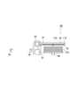
- FIG. 1 is a schematic plan view showing the overall configuration of an electronic component testing apparatus according to an embodiment of the present invention.
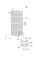
- FIG. 2 is a plan view showing the customer tray in the embodiment of the present invention.
- FIG. 3 is a side view of FIG.
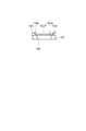
- FIG. 4 is a cross-sectional view taken along line IV-IV in FIG.
- FIG. 5 is a plan view showing the contact plate in the embodiment of the present invention.
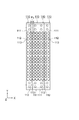
- FIG. 6 is a plan view showing a state in which the contact plates shown in FIG. 5 are connected.
- FIG. 9 is a side view of the first device transfer apparatus in the embodiment of the present invention.
- FIG. 10 is a plan view of FIG. FIG.
- FIG. 11 is a perspective view of the holding mechanism of the first device transfer apparatus shown in FIG.
- FIG. 12 is a plan view of a reinforcing plate in the embodiment of the present invention.
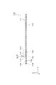
- FIG. 13 is a side view of FIG. 14 is a plan view showing a state in which a contact plate is mounted on the reinforcing plate shown in FIG.
- FIG. 15 is a side view of FIG.
- FIG. 16 is a side view (part 1) illustrating the operation of the first device transfer apparatus according to the embodiment of the present invention.
- FIG. 17 is a side view (part 2) illustrating the operation of the first device transfer apparatus according to the embodiment of the present invention.
- FIG. 18 is a side view (No. 3) showing the operation of the first device transfer apparatus in the embodiment of the present invention.
- FIG. 19 is a cross-sectional view showing the operation of placing the contact plate on the customer tray in the embodiment of the present invention.
- FIG. 20 is a cross-sectional view showing a state in which the contact plate is placed on the customer tray in the embodiment of the present invention.
- FIG. 21 is a side view (No. 4) showing the operation of the first device transfer apparatus in the embodiment of the present invention.
- FIG. 22 is a cross-sectional view showing the operation of inverting the contact plate and the customer tray in the embodiment of the present invention.
- FIG. 23 is a side view (No. 5) showing the operation of the first device transfer apparatus in the embodiment of the present invention.
- FIG. 24 is a cross-sectional view showing the operation of removing the customer tray from the contact plate after inversion in the embodiment of the present invention.
- FIG. 25 is a plan view showing a first interval changing device in the embodiment of the present invention.
- FIG. 26 is a side view of FIG.
- FIG. 27 is a side view showing the movable head of the first interval changing device in the embodiment of the present invention.
- FIG. 28 is a plan view of the movable head as seen from a view A in FIG.
- FIG. 29 is a plan view (part 1) illustrating a contact plate conveying operation by the first interval changing device according to the embodiment of the present invention.
- FIG. 30 is a plan view (part 2) illustrating the contact plate transfer operation by the first interval changing device according to the embodiment of the present invention.
- FIG. 31 is a plan view showing the setting operation of the contact plate by the first interval changing device in the embodiment of the present invention.
- FIG. 32 is a side view showing the plate moving device and the pressing device in the embodiment of the present invention.
- FIG. 33 is a plan view showing the plate moving device and the pressing device in the embodiment of the present invention.
- FIG. 34 is a side view (No. 1) showing the operation of the plate moving device and the pressing device in the embodiment of the present invention.
- FIG. 35 is a side view (part 2) illustrating the operation of the plate moving device and the pressing device according to the embodiment of the present invention.
- FIG. 36 is a side view (No. 3) showing operations of the plate moving device and the pressing device according to the embodiment of the present invention.
- FIG. 37 is a cross-sectional view showing the operation of bringing the DUT housed in the contact plate closer to the socket of the test head.
- FIG. 38 is a cross-sectional view showing a state in which the DUT accommodated in the contact plate is brought into contact with the socket of the test head.
- FIG. 39 is a side view (No. 4) showing the operation of the plate moving device and the pressing device in the embodiment of the present invention.
- FIG. 40 is a side view (No. 5) showing the operation of the plate moving device and the pressing device in the embodiment of the present invention.
- FIG. 41 is a side view (No. 6) illustrating operations of the plate moving device and the pressing device according to the embodiment of the present invention.
- FIG. 42 is a plan view showing a second gap changing device in the embodiment of the present invention.
- FIG. 43 is a plan view showing a second device transfer apparatus in the embodiment of the present invention.
- FIG. 1 is a schematic plan view showing the overall configuration of the electronic component testing apparatus in the present embodiment.
- the electronic component test apparatus 1 in this embodiment is an apparatus for testing an electronic device under test (DUT) such as a semiconductor integrated circuit element. As shown in FIG. 1, a handler 20 for handling a DUT, and a test are performed. A test head 10 that is in electrical contact with the DUT and a tester body 5 (see FIG. 32) that executes the DUT test are provided.
- DUT electronic device under test
- the handler 20 in the present embodiment includes a first device transfer device 30, a first interval changing device 40, a plate moving device 50, a pressing device 60, a second interval changing device 70, 2 device transfer device 80, plate return device 90, and tray transfer device 95, and a plurality (four in this example) of contact plates 110 (first) from one customer tray 100 (first tray).
- the plurality of DUTs are collectively transferred to the second tray), and the DUTs are handled in the handler 20 in a state where the DUTs are accommodated in the contact plates 110.
- the handling of the contact plate 110 by the handler 20 will be outlined.
- the first device transfer device 30 has a plurality of DUTs placed on one contact tray 110 from one customer tray 100. Are transferred in bulk.
- the first interval changing device 40 transfers the contact plate 110 from the first device transfer device 30 to the plate moving device 50 while increasing the interval between the contact plates 110.
- the reason why the space between the contact plates 110 is increased is to secure an area necessary for wiring or the like between the sockets 12 (see FIG. 33) on the test head 10.
- the plate moving device 50 supplies the contact plate 110 to the pressing device 60, the pressing device 60 presses the DUT accommodated in the contact plate 110 against the socket 12 of the test head 10, and the tester body 5 is connected to the test head. DUT test through 10.
- the contact plate 110 after the test is discharged from the pressing device 60 by the plate moving device 50, and the second device 70 is moved from the plate moving device 50 to the second device transfer device while the second interval changing device 70 narrows the interval between the contact plates 110.
- the contact plate 110 is transferred to 80.
- the second device transfer device 80 transfers the DUT from the contact plate 110 to the customer tray 100.
- the used contact plate 110 is returned from the second device transfer device 80 to the first device transfer device 30 by the plate return device 90.
- the customer tray 100 in which the DUT is empty is sent from the first device transfer device 30 to the second device transfer device 80 by the tray transfer device 95.
- FIGS. 5 to 7 show a contact plate in the present embodiment.
- FIG. 8 is a sectional view taken along line VIII-VIII in FIG.
- the customer tray 100 in this embodiment includes a flat tray body 101.
- a large number (136 in this example) of through holes 102 are formed on the main surface of the tray body 101.
- a large number of through holes 102 are arranged in a matrix (8 rows and 17 columns in this example) with a pitch in the X direction P 1 and a pitch in the Y direction P 2 .
- the through holes 102 each have a substantially rectangular opening 102a.
- substantially cross-shaped ribs 103 are erected.
- the first accommodating portion 104 is partitioned by the four ribs 103 surrounding the opening 102 a, and the DUT can be accommodated in the first accommodating portion 104.
- engagement holes 105 for engaging the first arms of the device transfer devices 30 and 80 are formed.
- the contact plate 110 includes a strip-shaped plate body 111 as shown in FIGS. As shown in FIG. 5, a convex portion 116 is formed on one side surface of the plate body 111, and a concave portion 117 is formed on the other side surface. By fitting the convex portion 116 of the contact plate 110 into the concave portion 117 of another contact plate 110, the contact plates 110 can be coupled to each other as shown in FIG.
- a large number (34 in this example) of through holes 112 are formed in the main surface of the plate body 111. These through holes 112 are arranged in a matrix (2 rows and 17 columns in this example) with a pitch of P 3 in the X direction and a pitch of P 4 in the Y direction. Further, in the present embodiment, as shown in FIG. 6, even when connecting the contact plate 110 to each other, the pitch between the through-hole 112 of an adjacent contact plate 110 is in the P 3.
- the through-holes 112 each have a substantially rectangular opening 112a. Ribs 113 are erected on four sides of the opening 112a.
- the second accommodating portion 114 is partitioned by four ribs 113 surrounding the opening 112a, and the DUT can be accommodated in the second accommodating portion 114.
- the number of second accommodating portions 114 is equal to the number of first accommodating portions 104 in one customer tray 100.
- the first storage part 104 and the second storage part 114 have the same arrangement. Therefore, a large number (136 in this example) of DUTs are simultaneously transferred between the customer tray 100 and the contact plate 110 by superimposing and inverting the four contact plates 110 on one customer tray 100. It is possible.
- the number of contact plates corresponding to one customer tray is not particularly limited. Further, the DUTs may be collectively transferred from the M customer trays to the N contact plates (however, M and N are natural numbers, and M ⁇ N). Further, the number of first accommodating portions formed on the customer tray and the number of second accommodating portions formed on the contact plate are not particularly limited.
- a groove 119 into which a shaft 123 of a reinforcing plate 120 described later is inserted is formed on the back surface of the plate body 111. Also. As shown in the figure, on both side surfaces of the plate main body 111, engagement holes 115 for engaging the second arms of the device transfer devices 30 and 80 are formed. Further, as shown in FIG. 5, insertion holes 118 into which the holding pins of the plate moving device 50 are inserted are formed in the vicinity of both ends of the plate main body 111.
- FIGS. 9 and 10 are a side view and a plan view of the first device transfer apparatus according to the present embodiment
- FIG. 11 is a perspective view showing a holding mechanism of the first device transfer apparatus shown in FIG. 9
- FIGS. 13 is a plan view and a side view of the reinforcing plate in the present embodiment
- FIGS. 14 and 15 are a plan view and a side view showing a state in which the contact plate is mounted on the reinforcing plate.
- the first device transfer device 30 of the handler 20 includes a holding mechanism 31 that holds the customer tray 100 and the contact plate 110 in an overlapping manner, and a reversing mechanism 36 that reverses the holding mechanism 31.
- An elevating mechanism 37 that elevates and lowers the reversing mechanism 36.
- the holding mechanism 31 and the reversing mechanism 36 in the present embodiment correspond to an example of the reversing unit in the present invention.
- the first device transfer device 30 inverts the contact plate 110 and the customer tray 100 in a state where the contact plate 110 is mounted on the reinforcing plate 120 shown in FIGS.
- the reinforcing plate 120 can mount four contact plates 110, and blocks 122 are provided at both upper and lower ends, and a shaft 123 is bridged between the blocks 122.
- the shaft 123 can be inserted into a groove 119 formed on the back surface of the contact plate 110.
- engagement holes 124 that can be engaged with the second arm 33 of the first device transfer device 30 are formed.
- the second device transfer apparatus 80 described later also uses the same material as the reinforcing plate 120.
- the holding mechanism 31 of the first device transfer device 30 includes a first arm 32 that grips the customer tray 100 and a substantially parallel arrangement with the first arm 32, and the four contact plates 110 are reinforced. And a second arm 33 for holding the plate 120.
- the first arm 32 has a pair of arm members 321 and 322 arranged to face each other with a predetermined interval.
- a gripping claw 323 that can be engaged with the engagement hole 105 of the customer tray 100 protrudes from the inner surface of each of the arm members 321 and 322.
- the pair of arm members 321 and 322 can be moved toward and away from each other by the two first opening / closing cylinders 34, and the pair of arm members 321 and 322 sandwich the customer tray 100 therebetween. As a result, the customer tray 100 is gripped by the first arm 32.
- the customer trays 100 are stacked and set in the first device transfer apparatus 30, and the uppermost customer tray 100 is positioned at a predetermined height by the elevator 39. It has become.
- the first arm 32 grips the customer tray 100 located at the uppermost stage.
- the second arm 33 also has a pair of arm members 331 and 332 arranged to face each other with a predetermined interval. Grip claws 333 and 334 that can be engaged with the engagement holes 115 and 124 of the contact plate 110 and the reinforcing plate 120 protrude from the inner surfaces of the arms 331 and 332, respectively.
- the pair of arm members 331 and 332 included in the second arm 33 can be moved toward and away from each other by the two second opening / closing cylinders 35.
- the second arm 33 grips the four contact arms 110 and the reinforcing plate 120 by sandwiching the contact plate 110 and the reinforcing plate 120 supported by the support base 38 between the pair of arm members 331 and 332. .
- the reversing mechanism 36 of the first device transfer device 30 can rotate the holding mechanism 31 180 degrees by a motor or the like.
- the elevating mechanism 37 can elevate and lower the holding mechanism 31 and the reversing mechanism 36 with an air cylinder or the like.
- 16 to 24 are diagrams for explaining the operation of the first device transfer apparatus according to the present embodiment.
- the lifting device 37 lowers the holding mechanism 31 positioned above the reinforcing plate 120 and the contact plate 110 supported by the support base 38.
- the lifting mechanism 37 raises the holding mechanism 31 and the reversing mechanism 36 holds, as shown in FIG.
- the mechanism 31 is rotated 180 degrees.
- the elevating mechanism 37 lowers the holding mechanism 31 and superimposes the contact plate 110 on the customer tray 100 as shown in FIGS.
- the lifting mechanism 37 raises the holding mechanism 31, and the reversing mechanism 36 rotates the holding mechanism 31 again by 180 degrees. Let By this rotation, as shown in FIG. 22, all the DUTs accommodated in the first accommodating part 104 of one customer tray 100 are collectively put in the second accommodating parts 114 of the four contact plates 110. Are transferred.
- the elevating mechanism 37 lowers the holding mechanism 31 to place the reinforcing plate 120 on the support base 38, and the second arm 33 releases the reinforcing plate 120 and the contact plate 110.
- the lifting mechanism 37 raises the holding mechanism 31, and the reversing mechanism 36 rotates the holding mechanism 31 again by 180 degrees. Thereby, as shown in FIG. 24, the customer tray 100 is removed from the contact plate 110.
- the customer tray 100 in which the DUT is empty, as shown in FIG. 1 is transferred from the first device transfer device 30 to the second device transfer by a tray forwarding device 95 including a pick-and-place device or the like. It is forwarded to the device 80.
- FIGS. 25 and 26 are a plan view and a side view showing the first interval changing device in the present embodiment
- FIGS. 27 and 28 are a side view and a plan view showing the movable head of the first interval changing device.
- the first interval changing device 40 of the handler 20 includes a pair of Y-direction rails 41, a movable arm 42, an elevating actuator 43, and a movable head 45.
- the Y direction rail 41 is bridged between the first device transfer device 30 and the plate moving device 50 along the Y direction.
- the Y-direction rail 41 supports a movable arm 42, and the movable arm 42 can move in the Y direction.
- the movable arm 42 is provided with a lifting actuator 43 constituted by an air cylinder or the like, and this lifting actuator 43 can move in the X direction.
- a movable head 45 is attached to the tip of the lift actuator 43, and the movable head 45 can be moved up and down by the lift actuator 43.
- the movable head 45 includes a base member 46, a holding member 47 that holds the contact plate 110, an interval changing mechanism 48 that changes the interval between the holding members 47, the base member 46, and the like. And a connecting mechanism 49 that connects the holding member 47.
- the base member 46 is fixed to the tip of the drive shaft of the lift actuator 43. Then, four holding members 47 are attached to the base member 46 via an interval changing mechanism 48 and a connecting mechanism 49.
- Each holding member 47 has a strip shape corresponding to each contact plate 110, and gripping claws 471 for gripping the contact plate 110 are provided at both ends thereof so as to be openable and closable.
- the number of holding members 47 included in the movable head 45 is not particularly limited to the above number, and is set according to the number of contact plates 110 corresponding to one customer tray 100, for example.
- the interval changing mechanism 48 includes an air cylinder 481 provided on the base member 46, a cam plate 482 fixed to the tip of a drive shaft of the air cylinder 481, and a cam follower 472 provided on the upper surface of each contact plate 110. , Is composed of.
- the cam plate 482 has four cam grooves 482a.
- Pitch of cam groove 482a has a pitch S 1 of the relatively narrow first, continuously varies between a relatively wide second pitch S 2.
- Cam followers 472 protruding from the upper surface of each contact plate 110 are slidably inserted into the four cam grooves 482a.
- the connecting mechanism 49 includes a connecting member 491 extending downward from the base member 46, and a linear guide 492 provided at the tip of the connecting member 491.
- the linear guide 492 is provided on the guide rail 493 fixed to the distal end of the connecting member 491 and the upper surface of each holding member 47, and is slidably engaged with the guide rail 493 along the X direction. And is composed of.
- the connecting mechanism 49 connects the holding member 47 to the base member 46 while allowing the interval changing mechanism 48 to change the interval between the holding members 47.
- FIG. 29 and FIG. 30 are plan views showing the contact plate conveying operation by the first interval changing device in the present embodiment
- FIG. 31 is a plan view showing the contact plate setting operation by the first interval changing device in the present embodiment. It is.
- the movable arm 42 moves on the Y-direction rail 41.
- the distance changing mechanism 48 of the movable head 45 by widening the pitch between the cam follower 472 from the first pitch S 1 in the second pitch S 2, increase the distance between the holding member 47.
- the movable arm 42 stops, and the elevating actuator 43 lowers the movable head 45 so that the four contact arms 110 are moved to the plate moving device 50. Placed on.
- the first interval changing device 40 uses the plate returning device 90 constituted by, for example, a rotating belt to transfer the four contact plates 110 returned from the second device transfer device 80 to the first device. It is also possible to move it onto the reinforcing plate 120 of the device transfer device 30.
- 32 and 33 are a side view and a plan view showing a plate moving device and a pressing device according to this embodiment.
- the plate moving device 50 of the handler 20 includes a pair of X direction rails 51 and two sets of moving bodies 52 and 55 as shown in FIGS. 32 and 33.
- the pair of X-direction rails 51 includes a first position L 1 (delivery position) for receiving the contact plate 110 from the first interval changing device 40 and a second position for delivering the contact plate 110 to the second interval changing device 70. It is provided substantially parallel to L 3 (delivery position) at a predetermined interval.
- a pressing device 60 is provided at a substantially central portion (second position L 2 (opposing position)) of the X-direction rail 51, and the test head 10 is moved upward in the handler 20 so as to face the pressing device 60. I'm coming from.
- the first moving body 52 (first moving means) includes a pair of holding members 53 and 54 provided on the X direction rail 51 so as to be slidable along the X direction.
- the holding members 53 and 54 are each provided with four holding pins 531 and 541 that can be inserted into the insertion holes 118 of the contact plate 110. Therefore, the first moving body 52 can hold the four contact plates 110 simultaneously.
- the second moving body 55 (second moving means) includes a pair of holding members 56 and 57 provided on the X direction rail 51 so as to be slidable along the X direction.
- Four holding pins 561 and 571 that can be inserted into the insertion holes 118 of the contact plate 110 are provided on 56 and 57, respectively. Therefore, the second moving body 55 can also hold the four contact plates 110 simultaneously.
- the number of contact plates 110 that can be simultaneously held by the first and second moving bodies 52 and 55 is not particularly limited to the above number, and for example, the number of contact plates 110 corresponding to one customer tray 100. Is set according to
- the first movable member 52 moves the contact plate 110 between a first position L 1 and the second position L 2.
- the second moving body 55 moves the contact plate 110 and a second position L 2 and the third position L 3. Further, the first moving body 52 and the second moving body 55 can move on the X-direction rail 51 independently of each other.
- the pressing device 60 includes a pressing plate 61 that presses the contact plate 110 against the test head 10, and a Z-direction actuator 62 that moves the pressing plate 61 up and down.
- the pressing device 60 is disposed between the pair of X-direction rails 61 in a plan view. Even when the pressing plate 61 is moved up and down by the Z-direction actuator 62, the pressing plate 61 and the X-direction rail 51 interfere with each other. There is nothing.
- the upper part (lower part in FIG. 32) of the test head 10 is provided with HiFix 11 (interface device) on which a large number (136 in this example) of sockets 12 are mounted.
- the contact plates 110 are arranged so as to correspond to the DUTs held on the contact plates 110. When the contact plate 110 is pressed toward the HiFix 11 of the test head 10 by the pressing device 60, the terminal HB of the DUT and the contact pin 13 of the socket 12 are in electrical contact (see FIGS. 37 and 38).
- 34 to 41 are diagrams for explaining the operation of the plate moving device and the pressing device in this embodiment.
- the first movable member 52 located in the first position L 1 on the X-direction rails 51, the four contact plate 110 To do. Then, as shown in FIG. 35, the first movable member 52 is moved on the X-direction rails 51 from the first position L 1 to the second position L 2.
- the pressing device 60 raises the pressing plate 61 by the Z-direction actuator 62, and the pressing plate 61 receives the four contact plates 110 from the first moving body 52, and the Z-direction actuator 62. Further raises the pressing plate 61.
- the DUT accommodated in the contact plate 110 is pressed against the socket 12 of the HiFix 11, and the terminal HB of the DUT and the contact pin 13 of the socket 12 are in electrical contact.
- the tester body 5 inputs / outputs a test signal to / from the DUT via the test head 10, thereby causing the DUT to be tested.
- the tester body 5 While the tester body 5 is running a test of the DUT, as shown in FIG. 39, the first moving body 52 is retracted from the second position L 2 to the first position L 1, the second mobile 55 moves from the third position L 3 to the second position L 2.
- the Z-direction actuator 62 of the pressing device 60 lowers the pressing plate 61, and the second moving body 55 removes the tested contact plate 110 from the pressing plate 61. receive.
- the second moving body 55 moves from the second position L 2 to the third position L 3 , and the second interval changing device 70 moves from the second moving body 55 to 4.
- the contact plates 110 are transferred to the second device transfer device 80.
- FIG. 42 is a plan view showing a second interval changing apparatus in the present embodiment
- FIG. 43 is a plan view showing a second device transfer apparatus in the present embodiment.
- the second interval changing device 70 of the handler 20 has a pair of Y-direction rails 71 and a Y-direction rail 71 along the Y direction, like the first interval changing device 40 described above.
- a movable arm 72 supported so as to be movable, a lift actuator supported so as to be movable along the X direction on the movable arm 72, and a movable head 75 movable up and down by the lift actuator are provided.
- the movable head 75 has an interval changing mechanism that changes the interval of the holding member that holds the contact plate 110, and moves the contact plate 110. While moving from the device 50 to the second device transfer device 80, the distance between the contact plates 110 can be reduced.
- the second interval changing device 70 includes a part of the plate returning device 90 in the operable range
- the contact plate 110 in which the DUT is empty is replaced with the second device transfer device 80. It is also possible to move from the reinforcing plate onto the plate return device 90.
- the second device transfer device 80 of the handler 20 has a holding mechanism that overlaps and inverts the contact plate 110 and the customer tray 100 in the same manner as the first device transfer device 30 described above. 81, a reversing mechanism 86 for reversing the holding mechanism 81, and a lifting mechanism for lifting and lowering the reversing mechanism 86.
- the second interval changing device 70 transfers the contact plate 110 from the plate moving device 50 to the second device transfer device 80 while narrowing the interval between the four contact plates 110. Then, the second device transfer device 80 superimposes the customer tray 100 on the four contact plates 110 and inverts them, thereby reversing all of the ones accommodated in the second accommodation portions 114 of the four contact plates 110. Are collectively transferred to the first accommodating portion 104 of the customer tray 100.
- the customer tray 100 in which the DUT is empty is forwarded from the first device transfer device 30 to the second device transfer device 80 by the tray transfer device 95 as shown in FIG.
- the used contact plate 110 is returned from the second device transfer device 80 to the first device transfer device 30 by the plate return device 90.
- the customer tray 100 in which the tested DUT is accommodated is stored in a state of being stacked on the second device transfer device 80.
- the customer trays 100 are taken out from the handler 20 and inserted into, for example, a dedicated classification machine.
- DUTs are classified into categories according to the results of tests performed by the tester body 5 of the electronic component test apparatus 1.
- a plurality of DUTs are collectively transferred between at least one customer tray 100 and a plurality of contact plates 110, and the contact plates 110 are routed in the handler 20. . Since the strip-shaped contact plate 110 can be narrowed until the strip-shaped contact plate 110 is conveyed to the vicinity of the test head 10, the electronic component testing apparatus 1 can be downsized as compared with the case where the test tray is used. Can be planned.
- the plate moving device 50 moves the distance between the contact plates 110. May be narrowed.
Landscapes
- Engineering & Computer Science (AREA)
- Computer Hardware Design (AREA)
- Microelectronics & Electronic Packaging (AREA)
- General Engineering & Computer Science (AREA)
- Physics & Mathematics (AREA)
- General Physics & Mathematics (AREA)
- Testing Of Individual Semiconductor Devices (AREA)
- Specific Conveyance Elements (AREA)
- Attitude Control For Articles On Conveyors (AREA)
Abstract
電子部品移載装置(30)は、1枚のカスタマトレイ(100)と、複数枚のコンタクトプレート(110)との間で複数の電子部品(DUT)を一括して移し替える。
Description
本発明は、半導体集積回路素子等の電子部品をトレイ間で移し替える電子部品移載装置及び電子部品の移載方法、並びに、その電子部品移載装置を備えた電子部品ハンドリング装置及び電子部品試験装置に関する。
電子部品を試験する電子部品試験装置として、被試験電子部品(以下単にDUT(Device Under Test)と称する。)間のピッチをテストヘッドにおけるソケット間のピッチに対応させるために、DUTをカスタマトレイからテストトレイに移し替えて、そのテストトレイにDUTを収容した状態で当該DUTをテストするものが知られている(例えば特許文献1参照)。
テストトレイではDUT間のピッチが常時広くなっており、上記の電子部品試験装置では、そのテストトレイにDUTを収容した状態でハンドリングするので、電子部品試験装置全体の大型化を招来しているという問題があった。
本発明が解決しようとする課題は、電子部品試験装置の小型化を図ることが可能な電子部品移載装置及び電子部品の移載方法を提供することである。
(1)本発明によれば、少なくとも1つの第1のトレイと、複数の第2のトレイとの間で複数の電子部品を一括して移し替えることを特徴とする電子部品移載装置が提供される(請求項1参照)。
上記発明においては特に限定されないが、少なくとも1つの前記第1のトレイと複数の前記第2のトレイとを重ね合わせて、実質的に反転させる反転手段を備えていることが好ましい(請求項2参照)。
上記発明においては特に限定されないが、前記反転手段は、複数の前記第2のトレイを略同一平面上に並べて保持することが好ましい(請求項3参照)。
上記発明においては特に限定されないが、前記第2のトレイの一方の側面には、凸部が形成され、前記第2のトレイの他方の側面には、前記凸部に対応する凹部が形成されており、前記凸部と前記凹部が嵌合することで、隣接する前記第2のトレイが相互に連結されることが好ましい(請求項4参照)。
上記発明においては特に限定されないが、前記第1のトレイは、前記電子部品を収容可能な複数の第1の収容部を有し、前記第2のトレイは、前記電子部品を収容可能な複数の第2の収容部を有し、前記反転手段は、前記第1の収容部と前記第2の収容部をそれぞれ対向させた状態で、前記第1のトレイと前記第2のトレイを実質的に反転させることが好ましい(請求項5参照)。
上記発明においては特に限定されないが、前記第1のトレイにおける前記第1の収容部の一部の配列と、前記第2のトレイにおける前記第2の収容部の全部の配列とは、実質的に同一であることが好ましい(請求項6参照)。
上記発明においては特に限定されないが、前記第1のトレイにおける第1の方向に沿った前記第1の収容部間のピッチは、前記第2のトレイにおける前記第1の方向に沿った前記第2の収容部間のピッチと実質的に同一であり、前記第1のトレイにおける第2の方向に沿った前記第1の収容部間のピッチは、前記第2のトレイにおける前記第2の方向に沿った前記第2の収容部間のピッチと実質的に同一であることが好ましい(請求項7参照)。
上記発明においては特に限定されないが、前記第1のトレイにおける前記第1の方向に沿った前記第1の収容部の数と、前記第2のトレイにおける前記第1の方向に沿った前記第2の収容部の数と、が実質的に同一であり、前記第1のトレイにおける前記第2の方向に沿った前記第1の収容部の数と、前記第2のトレイにおける前記第2の方向に沿った前記第2の収容部の数と、が相違していることが好ましい(請求項8参照)。
(2)本発明によれば、電子部品をハンドリングする電子部品ハンドリング装置であって、上記の電子部品移載装置と、複数の前記第2のトレイ間の間隔を第1の間隔又は第2の間隔に変更する間隔変更手段と、を備えていることを特徴とする電子部品ハンドリング装置が提供される(請求項9参照)。
上記発明においては特に限定されないが、前記間隔変更手段と前記第2のトレイを受け渡し可能な受渡位置と、前記第2のトレイがテストヘッドのコンタクト部と対向する対向位置と、の間で前記第2のトレイを移動させる移動手段と、前記移動手段から前記第2のトレイを受け取って、前記コンタクト部に前記電子部品を押しつける押圧手段と、を備え、前記移動手段と前記押圧手段は、前記対向位置で前記第2のトレイを受け渡すことが好ましい(請求項10参照)。
上記発明においては特に限定されないが、前記第2の間隔は、複数の前記第2のトレイに収容された複数の前記電子部品の配列と、前記テストヘッドにおける前記コンタクト部の配列と、がそれぞれ対応するような間隔であり、前記押圧手段は、複数の前記第2のトレイ間の間隔が前記第2の間隔となっている状態で前記電子部品を前記コンタクト部に押し付けることが好ましい(請求項11参照)。
上記発明においては特に限定されないが、前記電子部品移載装置は、少なくとも1つの前記第1のトレイから複数の前記第2のトレイへ複数の前記電子部品を一括して移し替える第1の電子部品移載装置と、複数の前記第2のトレイから少なくとも1つの前記第1のトレイへ複数の前記電子部品を一括して移し替える第2の電子部品移載装置と、を含み、前記間隔変更手段は、前記第1の電子部品移動載装置から前記第2のトレイを受け取って、複数の前記第2のトレイ間の間隔を前記第1の間隔から前記第2の間隔へ変更する第1の間隔変更手段と、複数の前記第2のトレイ間の間隔を前記第2の間隔から前記第1の間隔へ変更して、前記第2の電子部品移載装置へ前記第2のトレイを引き渡す第2の間隔変更手段と、を含み、前記移動手段は、前記第1の間隔変更手段から前記第2のトレイを受け取って、前記対向位置へ前記第2のトレイを移動させて、前記押圧手段へ前記第2のトレイを引き渡す第1の移動手段と、前記対向位置で前記押圧手段から前記第2のトレイを受け取って、前記受渡位置へ前記第2のトレイを移動させて、前記第2の間隔変更手段に前記第2のトレイを引き渡す第2の移動手段と、を含んでいることが好ましい(請求項12参照)。
(3)本発明によれば、上記の電子部品ハンドリング装置と、テストヘッドと、を備えた電子部品試験装置が提供される(請求項13参照)。
(4)本発明によれば、少なくとも1つの第1トレイと、複数の第2のトレイとの間で、複数の電子部品を一括して移し替えることを特徴とする電子部品移載方法が提供される(請求項14参照)。
上記発明においては特に限定されないが、少なくとも1つの前記第1のトレイと、複数の前記第2のトレイと、を重ね合わせる工程と、少なくとも1つの前記第1のトレイと複数の前記第2のトレイを反転させる工程と、を有していることが好ましい(請求項15参照)。
上記発明においては特に限定されないが、前記第1のトレイは、前記電子部品を収容可能な複数の第1の収容部を有し、前記第2のトレイは、前記電子部品を収容可能な複数の第2の収容部を有し、前記第1の収容部と前記第2の収容部をそれぞれ対向させた状態で、前記第1のトレイと前記第2のトレイを反転させることが好ましい(請求項16参照)。
本発明では、少なくとも1つの第1のトレイと、複数の第2のトレイとの間で複数の電子部品を一括して移し替えるので、電子部品試験装置の小型化を図ることができる。
以下、本発明の実施形態を図面に基づいて説明する。
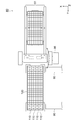
図1は本実施形態における電子部品試験装置の全体構成を示す概略平面図である。
本実施形態における電子部品試験装置1は、半導体集積回路素子等の被試験電子部品(DUT)を試験する装置であり、図1に示すように、DUTをハンドリングするハンドラ20と、試験の際にDUTに電気的に接触するテストヘッド10と、DUTの試験を実行するテスタ本体5(図32参照)と、を備えている。
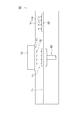
本実施形態におけるハンドラ20は、図1に示すように、第1のデバイス移載装置30、第1の間隔変更装置40、プレート移動装置50、押圧装置60、第2の間隔変更装置70、第2のデバイス移載装置80、プレート返送装置90、及びトレイ回送装置95を備えており、1枚のカスタマトレイ100(第1のトレイ)から複数(本例では4枚)のコンタクトプレート110(第2のトレイ)に複数のDUTを一括して移し替え、コンタクトプレート110にDUTを収容した状態で当該DUTをハンドラ20内でハンドリングする。
図1を参照しながら、ハンドラ20でのコンタクトプレート110の取り廻しについて概説すると、先ず、第1のデバイス移載装置30が、1枚のカスタマトレイ100から4枚のコンタクトプレート110に複数のDUTを一括して移載する。
次いで、第1の間隔変更装置40が、コンタクトプレート110間の間隔を広げながら、第1のデバイス移載装置30からプレート移動装置50にコンタクトプレート110に移載する。なお、コンタクトプレート110間の間隔を広げるのは、テストヘッド10上のソケット12(図33参照)の間に、配線等に必要な領域を確保するためである。
次いで、プレート移動装置50は、コンタクトプレート110を押圧装置60に供給し、押圧装置60が、コンタクトプレート110に収容されているDUTをテストヘッド10のソケット12に押し付けて、テスタ本体5がテストヘッド10を介してDUTの試験を実行する。
試験後のコンタクトプレート110を、プレート移動装置50が押圧装置60から払い出し、第2の間隔変更装置70が、コンタクトプレート110間の間隔を狭めながら、プレート移動装置50から第2のデバイス移載装置80にコンタクトプレート110を移載する。次いで、第2のデバイス移載装置80が、コンタクトプレート110からカスタマトレイ100にDUTを移載する。
なお、使用済みのコンタクトプレート110は、プレート返送装置90によって、第2のデバイス移載装置80から第1のデバイス移載装置30に返送される。一方、DUTが空となったカスタマトレイ100は、トレイ回送装置95によって、第1のデバイス移載装置30から第2のデバイス移載装置80に回送される。
ハンドラ20の各部の詳細な構成について説明する前に、先ず、カスタマトレイ100及びコンタクトプレート110の構成について説明する。
図2及び図3は本実施形態におけるカスタマトレイを示す平面図及び側面図、図4は図2のIV-IV線に沿った断面図、図5~図7は本実施形態におけるコンタクトプレートを示す平面図及び側面図、図8は図5のVIII-VIII線に沿った断面図である。
図2~図4に示すように、本実施形態におけるカスタマトレイ100は、平板状のトレイ本体101を備えている。このトレイ本体101の主面には、多数(本例では136個)の貫通孔102が形成されている。
多数の貫通孔102は、X方向のピッチがP1、Y方向のピッチがP2でマトリクス状(本例では8行17列)に配列されている。貫通孔102は、略矩形状の開口102aをそれぞれ有している。
開口102aの四隅の近傍には、略十字形状のリブ103がそれぞれ立設されている。開口102aを包囲する4つのリブ103によって、第1の収容部104が区画されており、この第1の収容部104内にDUTを収容することが可能となっている。また、トレイ本体101の両側面には、デバイス移載装置30,80の第1のアームが係合する係合穴105がそれぞれ形成されている。
一方、本実施形態におけるコンタクトプレート110は、図5~図8に示すように、短冊状のプレート本体111を備えている。図5に示すように、プレート本体111の一方の側面に凸部116が形成されていると共に、他方の側面に凹部117が形成されている。コンタクトプレート110の凸部116を、他のコンタクトプレート110の凹部117に嵌合させることで、図6に示すように、コンタクトプレート110同士を連結させることが可能となっている。
このプレート本体111の主面には、多数(本例では34個)の貫通孔112が形成されている。これらの貫通孔112は、X方向のピッチがP3、Y方向のピッチがP4でマトリクス状(本例では2行17列)に配列されている。また、本実施形態では、図6に示すように、コンタクトプレート110同士を連結した場合でも、隣接するコンタクトプレート110の貫通孔112間のピッチがP3となっている。
貫通孔112は、略矩形状の開口112aをそれぞれ有している。この開口112aの四方にはリブ113がそれぞれ立設されている。開口112aを包囲する4つのリブ113によって、第2の収容部114が区画されており、この第2の収容部114内にDUTを収容することが可能となっている。
本実施形態では、カスタマトレイ100における第1の収容部104のX方向のピッチP1と、コンタクトプレート110における第2の収容部114のX方向のピッチP3とが実質的に同一となっている(P1=P3)。同様に、カスタマトレイ100における第1の収容部104のY方向のピッチP2と、コンタクトプレート110における第2の収容部114のY方向のピッチP4とは実質的に同一となっている(P2=P4)。
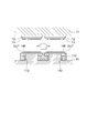
従って、本実施形態では、図6に示すように、4枚のコンタクトプレート110を連結することで、第2の収容部114の数が1枚のカスタマトレイ100における第1の収容部104の数と同一になると共に、第1の収容部104と第2の収容部114とが同一の配列となる。そのため、1枚のカスタマトレイ100に4枚のコンタクトプレート110を重ね合わせて反転させることで、カスタマトレイ100とコンタクトプレート110との間で多数(本例では136個)のDUTを同時に移載することが可能となっている。
なお、1枚のカスタマトレイに対応するコンタクトプレートの枚数は特に限定されない。また、M枚のカスタマトレイからN枚のコンタクトプレートにDUTを一括して移し替えてもよい(但し、M及びNは自然数であり、M<Nである)。さらに、カスタマトレイに形成される第1の収容部の数や、コンタクトプレートに形成される第2の収容部の数も特に限定されない。
図7に示すように、プレート本体111の裏面には、後述する補強プレート120のシャフト123が挿入される溝119が形成されている。また。同図に示すように、プレート本体111の両側面には、デバイス移載装置30,80の第2のアームが係合する係合穴115が形成されている。さらに、図5に示すように、プレート本体111の両端近傍には、プレート移動装置50の保持ピンが挿入される挿入孔118が形成されている。
以下に、本実施形態におけるハンドラ20の各部の詳細な構成について説明する。
図9及び図10は本実施形態における第1のデバイス移載装置の側面図及び平面図、図11は図9に示す第1のデバイス移載装置の保持機構を示す斜視図、図12及び図13は本実施形態における補強プレートの平面図及び側面図、図14及び図15は補強プレートにコンタクトプレートを搭載した状態を示す平面図及び側面図である。
ハンドラ20の第1のデバイス移載装置30は、図9及び図10に示すように、カスタマトレイ100とコンタクトプレート110を重ねて保持する保持機構31と、保持機構31を反転させる反転機構36と、反転機構36を昇降させる昇降機構37と、を備えている。なお、本実施形態における保持機構31及び反転機構36が、本発明における反転手段の一例に相当する。
なお、この第1のデバイス移載装置30は、図12~図15に示す補強プレート120にコンタクトプレート110を搭載した状態で、コンタクトプレート110とカスタマトレイ100を重ね合わせて反転させる。この補強プレート120は、4枚のコンタクトプレート110を搭載することが可能となっており、上下両端にブロック122が設けられ、このブロック122の間にはシャフト123がそれぞれ架け渡されている。このシャフト123は、コンタクトプレート110の裏面に形成された溝119に挿入可能となっている。また、この補強プレート120の両側面には、第1のデバイス移載装置30の第2のアーム33が係合可能な係合穴124が形成されている。なお、後述する第2のデバイス移載装置80でも、この補強プレート120と同様のものが使用される。
第1のデバイス移載装置30の保持機構31は、カスタマトレイ100を把持する第1のアーム32と、この第1のアーム32に実質的に平行に配置され、4枚のコンタクトプレート110と補強プレート120を把持する第2のアーム33と、を備えている。
図9~図11に示すように、第1のアーム32は、所定間隔を介して対向するように配置された一対のアーム部材321,322を有している。それぞれのアーム部材321,322の内側面からは、カスタマトレイ100の係合穴105に係合可能な把持爪323が突出している。この一対のアーム部材321,322は、2つの第1の開閉用シリンダ34によって、相互に接近/離反することが可能となっており、一対のアーム部材321,322がカスタマトレイ100を間に挟むことで、第1のアーム32によってカスタマトレイ100が把持される。
なお、図9に示すように、カスタマトレイ100が積層された状態で第1のデバイス移載装置30にセットされており、エレベータ39によって最上段のカスタマトレイ100が所定高さに位置するようになっている。第1のアーム32は、この最上段に位置するカスタマトレイ100を把持する。
一方、第2のアーム33も、所定間隔を介して対向するように配置された一対のアーム部材331,332を有している。それぞれのアーム331,332の内側面からは、コンタクトプレート110及び補強プレート120の係合穴115,124に係合可能な把持爪333,334が突出している。この第2のアーム33が有する一対のアーム部材331,332は、2つの第2の開閉用シリンダ35によって、相互に接近/離反することが可能となっている。この第2のアーム33は、支持台38に支持されているコンタクトプレート110及び補強プレート120を、一対のアーム部材331,332で挟み込むことで、4枚のコンタクトアーム110及び補強プレート120を把持する。
第1のデバイス移載装置30の反転機構36は、保持機構31をモータ等によって180度回転させることが可能となっている。また、昇降機構37は、保持機構31及び反転機構36をエアシリンダ等によって昇降させることが可能となっている。
次に、以上に説明した第1のデバイス移載装置30の動作について説明する。図16~図24は本実施形態における第1のデバイス移載装置の動作を説明するための図である。
先ず、図16に示すように、支持台38に支持されている補強プレート120及びコンタクトプレート110の上方に位置する保持機構31を、昇降装置37が下降させる。
次いで、保持機構31が第2のアーム33によって4枚のコンタクトプレート110と補強プレート120を把持した後、図17に示すように、昇降機構37が保持機構31を上昇させ、反転機構36が保持機構31を180度回転させる。
次いで、図18に示すように、昇降機構37が保持機構31を下降させて、図19及び図20に示すように、カスタマトレイ100の上にコンタクトプレート110を重ね合わせる。
次いで、保持機構31が第1のアーム32によってカスタマトレイ100を把持した後、図21に示すように、昇降機構37が保持機構31を上昇させ、反転機構36が保持機構31を再び180度回転させる。この回転により、図22に示すように、1枚のカスタマトレイ100の第1の収容部104に収容されていた全てのDUTが、4枚のコンタクトプレート110の第2の収容部114に一括して移載される。
次いで、昇降機構37が保持機構31を下降させて支持台38に補強プレート120を載置し、第2のアーム33が補強プレート120とコンタクトプレート110を解放する。
次いで、図23に示すように、昇降機構37が保持機構31を上昇させ、反転機構36が保持機構31を再度180度回転させる。これにより、図24に示すように、コンタクトプレート110の上からカスタマトレイ100が取り外される。
なお、DUTが空となったカスタマトレイ100は、図1に示すように、ピックアンドプレース装置等から構成されるトレイ回送装置95によって、第1のデバイス移載装置30から第2のデバイス移載装置80に回送される。
図25及び図26は本実施形態における第1の間隔変更装置を示す平面図及び側面図、図27及び図28はその第1の間隔変更装置の可動ヘッドを示す側面図及び平面図である。
ハンドラ20の第1の間隔変更装置40は、図25及び図26に示すように、一対のY方向レール41と、可動アーム42と、昇降アクチュエータ43と、可動ヘッド45と、を備えている。
Y方向レール41は、第1のデバイス移載装置30とプレート移動装置50との間にY方向に沿って架け渡されている。このY方向レール41は可動アーム42を支持しており、可動アーム42は、Y方向に移動することが可能となっている。また、可動アーム42には、エアシリンダ等から構成される昇降アクチュエータ43が設けられており、この昇降アクチュエータ43はX方向に移動することが可能となっている。この昇降アクチュエータ43の先端には可動ヘッド45が取り付けられており、可動ヘッド45は、昇降アクチュエータ43によって上下動することが可能となっている。
可動ヘッド45は、図27及び図28に示すように、ベース部材46と、コンタクトプレート110を保持する保持部材47と、保持部材47間の間隔を変更する間隔変更機構48と、ベース部材46と保持部材47とを連結する連結機構49と、を備えている。
ベース部材46は、昇降アクチュエータ43の駆動軸の先端に固定されている。そして、このベース部材46には、間隔変更機構48及び連結機構49を介して4つの保持部材47が取り付けられている。
それぞれの保持部材47は、個々のコンタクトプレート110に対応した短冊形状を有しており、コンタクトプレート110を把持するための把持爪471がその両端に開閉可能に設けられている。
なお、可動ヘッド45が有する保持部材47の数は、上記の数に特に限定されず、例えば、1枚のカスタマトレイ100に対応するコンタクトプレート110の枚数に応じて設定される。
間隔変更機構48は、ベース部材46に設けられたエアシリンダ481と、このエアシリンダ481の駆動軸の先端に固定されたカム板482と、各コンタクトプレート110の上面にそれぞれ設けられたカムフォロア472と、から構成されている。
図28に示すように、カム板482には、4本のカム溝482aが形成されている。これらのカム溝482aのピッチは、相対的に狭い第1のピッチS1と、相対的に広い第2のピッチS2との間で連続的に変化している。4本のカム溝482aには、各コンタクトプレート110の上面から突出するカムフォロア472がスライド可能にそれぞれ挿入されている。
従って、エアシリンダ481が駆動軸を伸長させると、図28中においてカムフォロア472がカム溝482a内を相対的に右側にスライドして、カムフォロア472間のピッチが第1のピッチS1に狭まる。カムフォロア472間のピッチが第1のピッチS1となっている状態では、保持部材47に保持されているコンタクトプレート110同士が密着している。
一方、エアシリンダ481が駆動軸を短縮させると、図28中においてカムフォロア472が、カム溝482a内を相対的に左側にスライドして、カムフォロア472間のピッチが第2のピッチS2に広がる。カムフォロア472間のピッチが第2のピッチS2になると、コンタクトプレート110に収容されているDUTの配列がテストヘッド10のソケット12の配列に対応する。
連結機構49は、図27に示すように、ベース部材46から下方に延びる連結部材491と、連結部材491の先端に設けられたリニアガイド492と、から構成されている。リニアガイド492は、連結部材491の先端に固定されたガイドレール493と、それぞれの保持部材47の上面に設けられ、ガイドレール493にX方向に沿ってスライド可能に係合しているスライドブロック473と、から構成されている。この連結機構49によって、間隔変更機構48による保持部材47間の間隔の変更を許容しつつ、保持部材47をベース部材46に連結している。
次に、以上に説明した第1の間隔変更装置40の動作について説明する。図29及び図30は本実施形態における第1の間隔変更装置によるコンタクトプレートの搬送動作を示す平面図、図31は本実施形態における第1の間隔変更装置によるコンタクトプレートのセッティング動作を示す平面図である。
先ず、図25に示すように、可動ヘッド45が第1のデバイス移載装置30の補強プレート120から4枚のコンタクトプレート110を把持すると、昇降アクチュエータ43によって可動ヘッド45が上昇する。
次いで、図29に示すように、可動アーム42がY方向レール41上を移動する。この移動の間、可動ヘッド45の間隔変更機構48は、カムフォロア472間のピッチを第1のピッチS1から第2のピッチS2に広げることで、保持部材47間の間隔を広げる。図30に示すように、可動ヘッド45がプレート移動装置50の上方に位置したら可動アーム42が停止し、昇降アクチュエータ43が可動ヘッド45を下降させて、4枚のコンタクトアーム110をプレート移動装置50に載置する。この際、間隔変更機構48によってカムフォロア472間のピッチが第2のピッチS2に変えられ、保持部材47間の間隔が広がっているので、コンタクトプレート110に収容されているDUTの配列がテストヘッド10のソケット12の配列に対応している。
因みに、図31に示すように、本実施形態の第1の間隔変更装置40は、プレート返送装置90の一部も動作可能範囲に包含している。そのため、この第1の間隔変更装置40は、例えば回転ベルト等から構成されるプレート返送装置90によって、第2のデバイス移載装置80から返送されてきた4枚のコンタクトプレート110を、第1のデバイス移載装置30の補強プレート120の上に移動させることも可能となっている。
図32及び図33は本実施形態におけるプレート移動装置と押圧装置を示す側面図及び平面図である。
ハンドラ20のプレート移動装置50は、図32及び図33に示すように、一対のX方向レール51と、2組の移動体52,55と、を備えている。
一対のX方向レール51は、第1の間隔変更装置40からコンタクトプレート110を受け取る第1の位置L1(受渡位置)と、第2の間隔変更装置70へコンタクトプレート110を引き渡す第2の位置L3(受渡位置)との間に、所定間隔を空けて実質的に平行に設けられている。このX方向レール51の略中央部分(第2の位置L2(対向位置))には押圧装置60が設けられており、この押圧装置60に対向するようにテストヘッド10がハンドラ20内に上方から臨んでいる。
第1の移動体52(第1の移動手段)は、X方向レール51上にX方向に沿ってスライド可能にそれぞれ設けられた一対の保持部材53,54から構成されている。保持部材53,54には、コンタクトプレート110の挿入孔118に挿入可能な保持ピン531,541がそれぞれ4本ずつ立設されている。従って、第1の移動体52は、4枚のコンタクトプレート110を同時に保持することが可能となっている。
第2の移動体55(第2の移動手段)も同様に、X方向レール51上にX方向に沿ってスライド可能にそれぞれ設けられた一対の保持部材56,57から構成されており、保持部材56,57には、コンタクトプレート110の挿入孔118に挿入可能な保持ピン561,571がそれぞれ4本ずつ立設されている。従って、第2の移動体55も、4枚のコンタクトプレート110を同時に保持することが可能となっている。
なお、第1及び第2の移動体52,55が同時に保持可能なコンタクトプレート110の枚数は、上記の数に特に限定されず、例えば、1枚のカスタマトレイ100に対応するコンタクトプレート110の枚数に応じて設定される。
第1の移動体52は、第1の位置L1と第2の位置L2との間でコンタクトプレート110を移動させる。一方、第2の移動体55は、第2の位置L2と第3の位置L3との間でコンタクトプレート110を移動させる。また、第1の移動体52と第2の移動体55は、X方向レール51上を相互に独立して移動することが可能となっている。
押圧装置60は、コンタクトプレート110をテストヘッド10に押し付ける押圧プレート61と、押圧プレート61を昇降させるZ方向アクチュエータ62と、を備えている。この押圧装置60は、平面視において一対のX方向レール61の間に配置されており、Z方向アクチュエータ62によって押圧プレート61を上下動させても、押圧プレート61とX方向レール51とが干渉することはない。
テストヘッド10の上部(図32では下部)には、多数(本例では136個)のソケット12が実装されたハイフィックス11(インタフェース装置)が設けられており、多数のソケット12は、4枚のコンタクトプレート110に保持されたDUTに対応するように配列されている。押圧装置60によってコンタクトプレート110がテストヘッド10のハイフィックス11に向かって押し付けられると、DUTの端子HBとソケット12のコンタクトピン13とが電気的に接触する(図37及び図38参照)。
次に、以上に説明したプレート移動装置50及び押圧装置60の動作について説明する。図34~図41は本実施形態におけるプレート移動装置及び押圧装置の動作を説明するための図である。
先ず、図34に示すように、第1の間隔変更装置40が、X方向レール51上の第1の位置L1に位置する第1の移動体52に、4枚のコンタクトプレート110を載置する。次いで、図35に示すように、第1の移動体52が、第1の位置L1から第2の位置L2までX方向レール51上を移動する。
次いで、図36に示すように、押圧装置60がZ方向アクチュエータ62によって押圧プレート61を上昇させて、押圧プレート61が第1の移動体52から4枚のコンタクトプレート110を受け取り、Z方向アクチュエータ62は押圧プレート61をさらに上昇させる。これにより、図37及び図38に示すように、コンタクトプレート110に収容されているDUTがハイフィックス11のソケット12に押し付けられ、DUTの端子HBとソケット12のコンタクトピン13とが電気的に接触する。この状態で、テスタ本体5(図32参照)がテストヘッド10を介してDUTに対して試験信号を入出力することで、当該DUTの試験が実行させる。
テスタ本体5がDUTの試験を実行している間に、図39に示すように、第1の移動体52が第2の位置L2から第1の位置L1に退避すると共に、第2の移動体55が第3の位置L3から第2の位置L2に移動する。そして、DUTの試験が終了したら、図40に示すように、押圧装置60のZ方向アクチュエータ62が押圧プレート61を下降させ、第2の移動体55が押圧プレート61から試験済みのコンタクトプレート110を受け取る。
次いで、図41に示すように、第2の移動体55は第2の位置L2から第3の位置L3に移動して、第2の間隔変更装置70が第2の移動体55から4枚のコンタクトプレート110を第2のデバイス移載装置80に移載する。
図42は本実施形態における第2の間隔変更装置を示す平面図、図43は本実施形態における第2のデバイス移載装置を示す平面図である。
ハンドラ20の第2の間隔変更装置70は、図42に示すように、上述の第1の間隔変更装置40と同様に、一対のY方向レール71と、Y方向レール71にY方向に沿って移動可能に支持された可動アーム72と、可動アーム72にX方向に沿って移動可能に支持された昇降アクチュエータと、昇降アクチュエータによって昇降可能な可動ヘッド75と、を備えている。
また、可動ヘッド75は、第1の間隔変更装置40の可動ヘッド45と同様に、コンタクトプレート110を保持する保持部材の間隔を変更する間隔変更機構を有しており、コンタクトプレート110をプレート移動装置50から第2のデバイス移載装置80に移動させる間に、コンタクトプレート110間の間隔を狭めることが可能となっている。
因みに、この第2の間隔変更装置70は、プレート返送装置90の一部を動作可能範囲に包含しているため、DUTが空となったコンタクトプレート110を、第2のデバイス移載装置80の補強プレートからプレート返送装置90上に移動させることも可能となっている。
ハンドラ20の第2のデバイス移載装置80は、図43に示すように、上述の第1のデバイス移載装置30と同様に、コンタクトプレート110とカスタマトレイ100とを重ね合わせて反転させる保持機構81と、保持機構81を反転させる反転機構86と、反転機構86を昇降させる昇降機構と、を備えている。
第2の間隔変更装置70は、4枚のコンタクトプレート110間の間隔を狭めながら、プレート移動装置50から第2のデバイス移載装置80にコンタクトプレート110を移載する。そして、第2のデバイス移載装置80は、4枚のコンタクトプレート110にカスタマトレイ100を重ね合わせて反転させることで、4枚のコンタクトプレート110の第2の収容部114に収容されていた全てのDUTを、カスタマトレイ100の第1の収容部104に一括して移し替える。
なお、DUTが空となったカスタマトレイ100は、図1に示すように、トレイ回送装置95によって第1のデバイス移載装置30から第2のデバイス移載装置80に回送される。一方、使用済みのコンタクトプレート110は、プレート返送装置90によって第2のデバイス移載装置80から第1のデバイス移載装置30に返送される。
試験済みのDUTが収容されたカスタマトレイ100は、第2のデバイス移載装置80に積層された状態で格納される。そして、所定数のカスタマトレイ100が格納されたら、ハンドラ20からカスタマトレイ100が取り出されて、例えば分類専用機に投入される。この分類専用機では、電子部品試験装置1のテスタ本体5による試験の結果に応じたカテゴリにDUTが分類される。
以上のように、本実施形態では、少なくとも1枚のカスタマトレイ100と、複数のコンタクトプレート110との間で、複数のDUTを一括して移し替え、そのコンタクトプレート110をハンドラ20内で取り廻す。この短冊状のコンタクトプレート110は、テストヘッド10の近くに搬送するまで間隔を狭めておくことができるので、上述のテストトレイを用いた場合と比較して、電子部品試験装置1の小型化を図ることができる。
なお、以上説明した実施形態は、本発明の理解を容易にするために記載されたものであって、本発明を限定するために記載されたものではない。したがって、上記の実施形態に開示された各要素は、本発明の技術的範囲に属する全ての設計変更や均等物をも含む趣旨である。
例えば、第1及び第2の間隔変更装置40,70によってコンタクトプレート110間の間隔を変更することに代えて、コンタクトプレート110を第1の位置L1から第2の位置L2に移動させる間に、プレート移動装置50がコンタクトプレート110間の間隔を広げ、コンタクトプレート110を第2の位置L2から第3の位置L3に移動させる間に、プレート移動装置50がコンタクトプレート110間の間隔を狭めてもよい。
20…ハンドラ
30…第1のデバイス移載装置
31…保持機構
36…反転機構
37…昇降機構
40…第1の間隔変更装置
45…可動ヘッド
46…ベース部材
47…保持部材
48…間隔変更機構
49…連結機構
50…プレート移動装置
60…押圧装置
70…第2の間隔変更装置
80…第2のデバイス移載装置
100…カスタマトレイ
101…トレイ本体
104…第1の収容部
110…コンタクトプレート
114…第2の収容部
116…凸部
117…凹部
120…補強プレート
30…第1のデバイス移載装置
31…保持機構
36…反転機構
37…昇降機構
40…第1の間隔変更装置
45…可動ヘッド
46…ベース部材
47…保持部材
48…間隔変更機構
49…連結機構
50…プレート移動装置
60…押圧装置
70…第2の間隔変更装置
80…第2のデバイス移載装置
100…カスタマトレイ
101…トレイ本体
104…第1の収容部
110…コンタクトプレート
114…第2の収容部
116…凸部
117…凹部
120…補強プレート
Claims (16)
- 少なくとも1つの第1のトレイと、複数の第2のトレイとの間で複数の電子部品を一括して移し替えることを特徴とする電子部品移載装置。
- 請求項1記載の電子部品移載装置であって、
少なくとも1つの前記第1のトレイと複数の前記第2のトレイとを重ね合わせて、実質的に反転させる反転手段を備えていることを特徴とする電子部品移載装置。 - 請求項2記載の電子部品移載装置であって、
前記反転手段は、複数の前記第2のトレイを略同一平面上に並べて保持することを特徴とする電子部品移載装置。 - 請求項3記載の電子部品移載装置であって、
前記第2のトレイの一方の側面には、凸部が形成され、
前記第2のトレイの他方の側面には、前記凸部に対応する凹部が形成されており、
前記凸部と前記凹部が嵌合することで、隣接する前記第2のトレイが相互に連結されることを特徴とする電子部品試験装置。 - 請求項1~4の何れかに記載の電子部品移載装置であって、
前記第1のトレイは、前記電子部品を収容可能な複数の第1の収容部を有し、
前記第2のトレイは、前記電子部品を収容可能な複数の第2の収容部を有し、
前記反転手段は、前記第1の収容部と前記第2の収容部をそれぞれ対向させた状態で、前記第1のトレイと前記第2のトレイを実質的に反転させることを特徴とする電子部品移載装置。 - 請求項5記載の電子部品移載装置であって、
前記第1のトレイにおける前記第1の収容部の一部の配列と、前記第2のトレイにおける前記第2の収容部の全部の配列とは、実質的に同一であることを特徴とする電子部品移載装置。 - 請求項5又は6に記載の電子部品移載装置であって、
前記第1のトレイにおける第1の方向に沿った前記第1の収容部間のピッチは、前記第2のトレイにおける前記第1の方向に沿った前記第2の収容部間のピッチと実質的に同一であり、
前記第1のトレイにおける第2の方向に沿った前記第1の収容部間のピッチは、前記第2のトレイにおける前記第2の方向に沿った前記第2の収容部間のピッチと実質的に同一であることを特徴とする電子部品移載装置。 - 請求項7記載の電子部品移載装置であって、
前記第1のトレイにおける前記第1の方向に沿った前記第1の収容部の数と、前記第2のトレイにおける前記第1の方向に沿った前記第2の収容部の数と、が実質的に同一であり、
前記第1のトレイにおける前記第2の方向に沿った前記第1の収容部の数と、前記第2のトレイにおける前記第2の方向に沿った前記第2の収容部の数と、が相違していることを特徴とする電子部品移載装置。 - 電子部品をハンドリングする電子部品ハンドリング装置であって、
請求項1~8の何れかに記載の電子部品移載装置と、
複数の前記第2のトレイ間の間隔を第1の間隔又は第2の間隔に変更する間隔変更手段と、を備えていることを特徴とする電子部品ハンドリング装置。 - 請求項9記載の電子部品ハンドリング装置であって、
前記間隔変更手段と前記第2のトレイを受け渡し可能な受渡位置と、前記第2のトレイがテストヘッドのコンタクト部と対向する対向位置と、の間で前記第2のトレイを移動させる移動手段と、
前記移動手段から前記第2のトレイを受け取って、前記コンタクト部に前記電子部品を押しつける押圧手段と、を備え、
前記移動手段と前記押圧手段は、前記対向位置で前記第2のトレイを受け渡すことを特徴とする電子部品ハンドリング装置。 - 請求項10記載の電子部品ハンドリング装置であって、
前記第2の間隔は、複数の前記第2のトレイに収容された複数の前記電子部品の配列と、前記テストヘッドにおける前記コンタクト部の配列と、がそれぞれ対応するような間隔であり、
前記押圧手段は、複数の前記第2のトレイ間の間隔が前記第2の間隔となっている状態で前記電子部品を前記コンタクト部に押し付けることを特徴とする電子部品ハンドリング装置。 - 請求項10又は11に記載の電子部品ハンドリング装置であって、
前記電子部品移載装置は、
少なくとも1つの前記第1のトレイから複数の前記第2のトレイへ複数の前記電子部品を一括して移し替える第1の電子部品移載装置と、
複数の前記第2のトレイから少なくとも1つの前記第1のトレイへ複数の前記電子部品を一括して移し替える第2の電子部品移載装置と、を含み、
前記間隔変更手段は、
前記第1の電子部品移動載装置から前記第2のトレイを受け取って、複数の前記第2のトレイ間の間隔を前記第1の間隔から前記第2の間隔へ変更する第1の間隔変更手段と、
複数の前記第2のトレイ間の間隔を前記第2の間隔から前記第1の間隔へ変更して、前記第2の電子部品移載装置へ前記第2のトレイを引き渡す第2の間隔変更手段と、を含み、
前記移動手段は、
前記第1の間隔変更手段から前記第2のトレイを受け取って、前記対向位置へ前記第2のトレイを移動させて、前記押圧手段へ前記第2のトレイを引き渡す第1の移動手段と、
前記対向位置で前記押圧手段から前記第2のトレイを受け取って、前記受渡位置へ前記第2のトレイを移動させて、前記第2の間隔変更手段に前記第2のトレイを引き渡す第2の移動手段と、を含んでいることを特徴とする電子部品ハンドリング装置。 - 請求項9~12の何れかに記載の電子部品ハンドリング装置と、
テストヘッドと、を備えた電子部品試験装置。 - 少なくとも1つの第1トレイと、複数の第2のトレイとの間で、複数の電子部品を一括して移し替えることを特徴とする電子部品移載方法。
- 請求項14記載の電子部品移載方法であって、
少なくとも1つの前記第1のトレイと、複数の前記第2のトレイと、を重ね合わせる工程と、
少なくとも1つの前記第1のトレイと複数の前記第2のトレイを反転させる工程と、を有していることを特徴とする電子部品移載方法。 - 請求項15記載の電子部品移載方法であって、
前記第1のトレイは、前記電子部品を収容可能な複数の第1の収容部を有し、
前記第2のトレイは、前記電子部品を収容可能な複数の第2の収容部を有し、
前記第1の収容部と前記第2の収容部をそれぞれ対向させた状態で、前記第1のトレイと前記第2のトレイを反転させることを特徴とする電子部品移載方法。
Priority Applications (3)
| Application Number | Priority Date | Filing Date | Title |
|---|---|---|---|
| PCT/JP2009/061212 WO2010146709A1 (ja) | 2009-06-19 | 2009-06-19 | 電子部品移載装置及び電子部品の移載方法 |
| JP2011519386A JPWO2010146709A1 (ja) | 2009-06-19 | 2009-06-19 | 電子部品移載装置及び電子部品の移載方法 |
| TW099113240A TWI409204B (zh) | 2009-06-19 | 2010-04-27 | Electronic component processing device and electronic component testing device |
Applications Claiming Priority (1)
| Application Number | Priority Date | Filing Date | Title |
|---|---|---|---|
| PCT/JP2009/061212 WO2010146709A1 (ja) | 2009-06-19 | 2009-06-19 | 電子部品移載装置及び電子部品の移載方法 |
Publications (1)
| Publication Number | Publication Date |
|---|---|
| WO2010146709A1 true WO2010146709A1 (ja) | 2010-12-23 |
Family
ID=43356047
Family Applications (1)
| Application Number | Title | Priority Date | Filing Date |
|---|---|---|---|
| PCT/JP2009/061212 Ceased WO2010146709A1 (ja) | 2009-06-19 | 2009-06-19 | 電子部品移載装置及び電子部品の移載方法 |
Country Status (3)
| Country | Link |
|---|---|
| JP (1) | JPWO2010146709A1 (ja) |
| TW (1) | TWI409204B (ja) |
| WO (1) | WO2010146709A1 (ja) |
Cited By (5)
| Publication number | Priority date | Publication date | Assignee | Title |
|---|---|---|---|---|
| TWI631348B (zh) * | 2017-12-29 | 2018-08-01 | 鴻勁精密股份有限公司 | 電子元件轉載裝置及其應用之測試分類設備 |
| JP2019048661A (ja) * | 2017-09-12 | 2019-03-28 | 富士ゼロックス株式会社 | 部品移載治具及び部品移載方法 |
| JP2020018975A (ja) * | 2018-08-01 | 2020-02-06 | 株式会社Fuji | ノズルステーション対応のノズル洗浄用治具 |
| CN110950025A (zh) * | 2019-12-26 | 2020-04-03 | 深圳市世铎自动化设备有限公司 | 一种翻转装置 |
| CN121376562A (zh) * | 2025-12-22 | 2026-01-23 | 昆山倬跃蓝天电子科技有限公司 | 自动翻面设备 |
Families Citing this family (3)
| Publication number | Priority date | Publication date | Assignee | Title |
|---|---|---|---|---|
| CN112079110B (zh) * | 2020-09-02 | 2022-01-11 | 上海克来机电自动化工程股份有限公司 | 一种传输夹具 |
| CN113816118B (zh) * | 2021-11-19 | 2022-02-11 | 四川明泰电子科技有限公司 | 一种ic芯片检测上料工装 |
| TWI843278B (zh) * | 2022-11-08 | 2024-05-21 | 鴻勁精密股份有限公司 | 載運機構及輸送裝置 |
Citations (3)
| Publication number | Priority date | Publication date | Assignee | Title |
|---|---|---|---|---|
| WO2007135710A1 (ja) * | 2006-05-18 | 2007-11-29 | Advantest Corporation | 電子部品試験装置 |
| WO2008139853A1 (ja) * | 2007-05-09 | 2008-11-20 | Advantest Corporation | 電子部品試験装置、電子部品試験システム及び電子部品の試験方法 |
| JP2009049347A (ja) * | 2007-08-22 | 2009-03-05 | Secron Co Ltd | テストハンドラーのバッファトレイピッチを調節する方法及び装置 |
-
2009
- 2009-06-19 WO PCT/JP2009/061212 patent/WO2010146709A1/ja not_active Ceased
- 2009-06-19 JP JP2011519386A patent/JPWO2010146709A1/ja active Pending
-
2010
- 2010-04-27 TW TW099113240A patent/TWI409204B/zh active
Patent Citations (3)
| Publication number | Priority date | Publication date | Assignee | Title |
|---|---|---|---|---|
| WO2007135710A1 (ja) * | 2006-05-18 | 2007-11-29 | Advantest Corporation | 電子部品試験装置 |
| WO2008139853A1 (ja) * | 2007-05-09 | 2008-11-20 | Advantest Corporation | 電子部品試験装置、電子部品試験システム及び電子部品の試験方法 |
| JP2009049347A (ja) * | 2007-08-22 | 2009-03-05 | Secron Co Ltd | テストハンドラーのバッファトレイピッチを調節する方法及び装置 |
Cited By (6)
| Publication number | Priority date | Publication date | Assignee | Title |
|---|---|---|---|---|
| JP2019048661A (ja) * | 2017-09-12 | 2019-03-28 | 富士ゼロックス株式会社 | 部品移載治具及び部品移載方法 |
| TWI631348B (zh) * | 2017-12-29 | 2018-08-01 | 鴻勁精密股份有限公司 | 電子元件轉載裝置及其應用之測試分類設備 |
| JP2020018975A (ja) * | 2018-08-01 | 2020-02-06 | 株式会社Fuji | ノズルステーション対応のノズル洗浄用治具 |
| JP7104581B2 (ja) | 2018-08-01 | 2022-07-21 | 株式会社Fuji | ノズルステーション対応のノズル洗浄用治具 |
| CN110950025A (zh) * | 2019-12-26 | 2020-04-03 | 深圳市世铎自动化设备有限公司 | 一种翻转装置 |
| CN121376562A (zh) * | 2025-12-22 | 2026-01-23 | 昆山倬跃蓝天电子科技有限公司 | 自动翻面设备 |
Also Published As
| Publication number | Publication date |
|---|---|
| TWI409204B (zh) | 2013-09-21 |
| JPWO2010146709A1 (ja) | 2012-11-29 |
| TW201100311A (en) | 2011-01-01 |
Similar Documents
| Publication | Publication Date | Title |
|---|---|---|
| WO2010146709A1 (ja) | 電子部品移載装置及び電子部品の移載方法 | |
| JPWO2011007419A1 (ja) | 電子部品押圧装置、電子部品試験装置及びインタフェース装置 | |
| CN107219451B (zh) | 用于制造基板的装置和方法 | |
| KR101163628B1 (ko) | 전자부품 시험장치 및 전자부품 시험 시스템 | |
| US10613138B2 (en) | Method and device for loading and unloading devices under test into a tester by flipping | |
| KR101386331B1 (ko) | 웨이퍼 반송 장치 | |
| CN107533102B (zh) | 元件处理器 | |
| US20110147436A1 (en) | Welding equipment | |
| WO2009144790A1 (ja) | 電子部品ハンドリング装置、電子部品試験装置および電子部品保持トレイ | |
| CN108362914B (zh) | 多转塔式测试设备 | |
| JPWO2008142754A1 (ja) | 電子部品試験装置及び電子部品試験方法 | |
| CN114035009B (zh) | 电子部件处理装置及电子部件试验装置 | |
| JPH06166428A (ja) | ワーク移載装置 | |
| KR20180013316A (ko) | 반도체 소자 테스트 장치 및 방법 | |
| WO2010146708A1 (ja) | 電子部品移載装置及びそれを備えた電子部品試験装置 | |
| KR101452095B1 (ko) | 트레이 이송 장치 | |
| JP4450081B2 (ja) | 部品試験装置 | |
| JP5314668B2 (ja) | 電子部品移載装置およびそれを備えた電子部品試験装置 | |
| KR101106972B1 (ko) | 전자부품 시험장치 | |
| CN109720872B (zh) | 上下料机构及物料传输方法 | |
| KR101042652B1 (ko) | 전자부품 시험장치 | |
| KR20090122662A (ko) | 피검사체의 검사 방법 및 테스트 핸들러 | |
| KR100528706B1 (ko) | 반도체 소자 테스트 핸들러의 트레이 이송장치 | |
| TW202334654A (zh) | 模組處理器及設置在該模組處理器的傳送工具 | |
| JP2006126063A (ja) | 半導体検査装置およびicソケット |
Legal Events
| Date | Code | Title | Description |
|---|---|---|---|
| 121 | Ep: the epo has been informed by wipo that ep was designated in this application |
Ref document number: 09846202 Country of ref document: EP Kind code of ref document: A1 |
|
| WWE | Wipo information: entry into national phase |
Ref document number: 2011519386 Country of ref document: JP |
|
| NENP | Non-entry into the national phase |
Ref country code: DE |
|
| 122 | Ep: pct application non-entry in european phase |
Ref document number: 09846202 Country of ref document: EP Kind code of ref document: A1 |