WO2010146621A1 - ストリップ鋳造方法及び双ロール鋳造機 - Google Patents
ストリップ鋳造方法及び双ロール鋳造機 Download PDFInfo
- Publication number
- WO2010146621A1 WO2010146621A1 PCT/JP2009/002704 JP2009002704W WO2010146621A1 WO 2010146621 A1 WO2010146621 A1 WO 2010146621A1 JP 2009002704 W JP2009002704 W JP 2009002704W WO 2010146621 A1 WO2010146621 A1 WO 2010146621A1
- Authority
- WO
- WIPO (PCT)
- Prior art keywords
- molten metal
- strip
- nozzle piece
- actuator
- thickness
- Prior art date
- Legal status (The legal status is an assumption and is not a legal conclusion. Google has not performed a legal analysis and makes no representation as to the accuracy of the status listed.)
- Ceased
Links
Images

Classifications
-
- B—PERFORMING OPERATIONS; TRANSPORTING
- B22—CASTING; POWDER METALLURGY
- B22D—CASTING OF METALS; CASTING OF OTHER SUBSTANCES BY THE SAME PROCESSES OR DEVICES
- B22D11/00—Continuous casting of metals, i.e. casting in indefinite lengths
- B22D11/06—Continuous casting of metals, i.e. casting in indefinite lengths into moulds with travelling walls, e.g. with rolls, plates, belts, caterpillars
-
- B—PERFORMING OPERATIONS; TRANSPORTING
- B22—CASTING; POWDER METALLURGY
- B22D—CASTING OF METALS; CASTING OF OTHER SUBSTANCES BY THE SAME PROCESSES OR DEVICES
- B22D11/00—Continuous casting of metals, i.e. casting in indefinite lengths
- B22D11/06—Continuous casting of metals, i.e. casting in indefinite lengths into moulds with travelling walls, e.g. with rolls, plates, belts, caterpillars
- B22D11/0637—Accessories therefor
- B22D11/064—Accessories therefor for supplying molten metal
Definitions
- the present invention relates to a strip casting method and a twin roll casting machine.
- FIG. 1 shows an example of a conventional twin roll casting machine, which includes a pair of cooling rolls 1 arranged horizontally and a pair of side weirs 2 attached to the cooling roll 1.
- the cooling roll 1 is configured such that cooling water flows through the roll 1 and the roll gap G can be adjusted in accordance with the thickness of the strip 3 to be produced.
- the rotation direction and speed of the cooling roll 1 are set so that the outer peripheral surface of each cooling roll 1 moves from the upper side toward the roll gap G at a constant speed.
- One side weir 2 is in surface contact with one end of each cooling roll 1, and the other side weir 2 is in surface contact with the other end of each cooling roll 1, and is surrounded by the cooling roll 1 and the side weir 2.
- the nozzle piece 4 for supplying molten metal is arranged so as to be located immediately above the roll gap G.
- the nozzle piece 4 has an elongated nozzle trough 6 for receiving the molten metal 5 at the top, and an opening 7 for supplying the molten metal 5 from the nozzle trough 6 to the cooling roll 1 at a lower end portion of the longitudinal side wall.
- a plurality of holes are formed so as to be aligned along the axis of the cooling roll 1, and when the molten metal 5 is poured into the nozzle trough 6, a molten metal pool 8 that contacts the outer peripheral surface of the cooling roll 1 is formed.
- the cooling roll 1 when the cooling roll 1 is rotated by forming the molten metal pool 8 while removing the heat from the cooling roll 1 by circulating the cooling water, the molten metal 5 is solidified on the outer peripheral surface of the cooling roll 1.
- the solidified shell S is formed.
- the solidified shell S formed on the outer peripheral surface of the cooling roll 1 is pasted together at the roll gap G, and is sent out as a strip 3 downward. At this time, a load is applied to the neck portions of the cooling rolls 1 so as to approach each other so that the produced strip 3 has a target plate thickness.
- Patent Document 1 detects the liquid level position of molten steel during operation, controls the rotational speed of a twin roll according to the height of the liquid level, and tries to obtain the steel plate with uniform board thickness.
- Patent Document 2 detects the current molten metal surface of the molten metal on the surface of the cooling drum when manufacturing a thin metal plate, and the solidified shell generated at the location where the molten metal surface contacts the surface of the cooling drum is the roll gap.
- Patent document 3 grasps the change of the casting pool height position when manufacturing the strip, and controls the rotation speed of the casting roll and the flow rate of the molten metal supplied to the casting pool to change the thickness of the strip. It is intended to suppress.
- the control to increase the thickness of the strip 3 is performed by lowering the rotation speed of the cooling roll 1 (lowering the rotation speed) or deepening the molten metal pool 8 to raise the free liquid level, and the metal is cooled. This is achieved by extending the time of touching the outer peripheral surface of the roll 1.
- the control to reduce the thickness of the strip 3 is performed by increasing the number of rotations of the cooling roll 1 (increasing the rotation speed) or by shallowing the molten metal reservoir 8 to lower the free liquid level position. This is achieved by reducing the time during which the metal touches the outer peripheral surface of the cooling roll 1.
- JP 60-049836 A Japanese Unexamined Patent Publication No. Sho 63-224846 JP-A-10-263758
- the moving speed of the strip 3 fed from the twin roll casting machine also changes according to the rotation speed of the cooling roll 1. It is necessary to adjust the plate passing speed of the strip 3 in the rolling device, the cooling device, and the winding device located in the subsequent process so as to correspond to the change in the number of rotations of the cooling roll 1. Speed control is required.
- the range in which the nozzle piece 4 is immersed fluctuates, and the molten metal pool 8 is swung.
- impurities such as oxides adhering to the nozzle piece 4 fall into the molten metal pool 8 and solidify. If it is caught in the shell, the quality of the strip 3 is deteriorated.
- the thickness variation of the strip 3 is not influenced only by the time when the metal is in contact with the outer peripheral surface of the cooling roll 1, but the surface roughness and cleanliness of the outer peripheral surface of the cooling roll 1 (adhesive layer such as oxide) Therefore, it is difficult to adjust the thickness of the strip 3 by paying attention only to the depth of the molten metal reservoir 8 because it is also affected by the composition of the atmospheric gas in the place where the twin roll casting machine is installed.
- the present invention has been made in view of the above-described circumstances, and an object of the present invention is to appropriately adjust the strip thickness while avoiding quality defects.
- the molten metal supplied from the tundish is cooled as a molten metal pool in which a predetermined range of the nozzle piece is immersed through a nozzle piece arranged between a pair of cooling rolls.
- the tundish will move to the molten metal pool.
- the amount of molten metal to be filled is reduced to make the molten metal reservoir shallow, and in parallel with this molten metal replenishment operation, the free liquid surface position of the molten metal reservoir is obtained, so that the relative position of the nozzle piece to the molten liquid free liquid surface is constant.
- the nozzle piece is displaced vertically.
- An actuator for adjusting the position of the molten metal up and down, a gate provided in the molten metal supply passage from the tundish to the nozzle piece and opened and closed by the actuator for adjusting the flow rate, the free liquid level of the molten metal pool and the outer peripheral surface of the cooling roll Which measures the thickness of the strip sent from between the cooling rolls, a position calculating means for obtaining the current free liquid level position of the molten metal pool based on an image signal transmitted from the camera, A thickness sensor and an actuator for adjusting the flow rate according to the measured value of the plate thickness sensor are operated, and the position calculating And a control means for operating the actuator for position adjustment according to the calculated value, and a deviation between a predetermined target value of the strip thickness and a measured value of the strip
- the strip thickness starts to decrease, the lack of heat removal is compensated for by increasing the time during which the molten metal pool is deepened and the metal is in contact with the outer peripheral surface of the cooling roll.
- the free liquid surface of the molten metal pool and the nozzle piece The nozzle piece is displaced in the vertical direction so that the relative position is constant, and the control of preventing the molten metal pool from swinging is also used, so that impurities such as oxides adhering to the nozzle piece fall into the molten metal pool.
- the strip thickness can be adjusted appropriately while avoiding poor quality without being caught in the solidified shell.
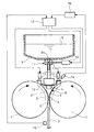
- FIG. 2 shows an example of the twin roll casting machine of the present invention.
- a pair of cooling rolls 1 arranged horizontally a pair of side weirs 2 attached to the cooling roll 1, and a nozzle piece 4.
- a tundish 9 for storing the molten metal 5 to be supplied to the nozzle piece 4 a slide gate 11 provided in the molten metal supply flow path from the tundish 9 to the nozzle piece 4 and opened and closed by a flow rate adjusting actuator 10.
- a support 12 that supports the nozzle piece 4 and can be displaced up and down and a position adjustment actuator 13 that displaces the nozzle piece 4 up and down via the support 12 are provided.
- the slide gate 11 has a partition plate 11a capable of closing the hole 9a for flowing down the molten metal formed in the bottom of the tundish 9, and the actuator 10 moves the partition plate 11a to adjust the opening degree of the hole 9a.
- the camera 14 that captures the boundary between the free liquid level of the molten metal pool 8 and the outer peripheral surface of the cooling roll 1, and image analysis processing is performed based on the image signal transmitted from the camera 14 to perform the molten metal pool.
- a position calculating means 15 for determining the current free liquid level position
- a plate thickness sensor 16 for measuring the plate thickness of the strip 3 fed from between the cooling rolls 1, and a flow rate according to the measured value of the plate thickness sensor 16.
- a control unit 17 that operates the adjustment actuator 10 and operates the position adjustment actuator 13 in accordance with the calculated value of the position calculation unit 15.
- a screw jack is used for the actuators 10 and 13 and an X-ray gauge is used for the plate thickness sensor 16, for example.
- the control means 17 uses the deviation between the target value of the strip 3 thickness and the measured thickness of the strip 3 obtained from the thickness sensor 16 as a parameter when the strip thickness of the strip 3 starts to decrease during operation.
- the actuator 10 for adjusting the flow rate is operated so that the replenishment amount of the molten metal 5 from the tundish 9 to the molten metal reservoir 8 temporarily increases, the molten metal reservoir 8 is deepened to raise the free liquid level position, and the cooling roll
- the plate thickness gradual increase control that extends the time during which the metal (molten metal 5 and solidified shell S) is in contact with the outer peripheral surface of 1, when the plate thickness of the strip 3 starts to increase during operation.
- the flow rate adjusting actuator 10 is operated so that the replenishment amount of the molten metal 5 from the dish 9 to the molten metal reservoir 8 is temporarily reduced, the molten metal reservoir 8 is shallowed to lower the free liquid level, and the metal is the cooling roll 1 Outer peripheral surface Performing a thickness decreasing control to reduce the The times mentioned, but does not changing the rotation
- the thickness of the strip 3 increases as the molten metal reservoir 8 is deeper, but the thickness of the strip 3 is not determined only by the position of the free liquid surface of the molten metal reservoir 8. Moreover, the relationship between the thickness of the solidified shell S and the cooling time is not actually a simple proportional relationship, and the solidification rate tends to gradually decrease, but for convenience, the solidification rate during operation is unchanged. Assuming that, a value of solidification constant K [mm / min 0.5 ] may be used.
- the control means 17 is based on the current free liquid surface position of the molten metal reservoir 8 obtained from the position calculating means 15 and increases the replenishment amount of the molten metal 5 to increase the free liquid.
- the position adjusting actuator 13 is operated so that the nozzle piece 4 rises following the free liquid level position, and the relative position of the free liquid level between the nozzle piece 4 and the molten metal reservoir 8 is made constant.
- the nozzle piece 4 is used for position adjustment so as to descend following the free liquid level position.
- the actuator 13 is operated to execute position lowering control for keeping the relative position of the free liquid level of the nozzle piece 4 and the molten metal reservoir 8 constant.
- the position calculation means 15 obtains the current free liquid level position of the molten metal reservoir 8, and the control means 17 sets the preset plate 3 of the strip 3. While comparing the target value of the thickness with the measured value of the thickness of the strip 3 obtained from the thickness sensor 16, the actuator 10 for adjusting the flow rate is operated as described below, and the molten metal pool obtained from the position calculating means 15 is obtained.
- the position adjusting actuator 13 is operated according to the current free liquid level position of No. 8.
- the control means 17 causes the actuator 10 for adjusting the flow rate so that the opening degree of the slide gate 11 is expanded for a predetermined time.
- the molten metal reservoir 8 is deepened, the position of the free liquid level is increased, the time during which the metal (the molten metal 5 and the solidified shell S) is in contact with the outer peripheral surface of the cooling roll 1 is extended, the lack of heat removal is eliminated, and the strip 3 The plate thickness gradually increases toward the target value.
- the control means 17 operates the position adjusting actuator 13 so that the nozzle piece 4 rises following the free liquid level position, thereby freeing the nozzle piece 4 and the molten metal reservoir 8. Since the relative position of the liquid level is kept constant without changing, the molten metal pool 8 does not swing. Therefore, it is possible to avoid the defective quality of the strip 3 caused by impurities such as oxides adhering to the nozzle piece 4 dropping into the molten metal pool 8 and being caught in the solidified shell S.
- the control means 17 causes the actuator 10 for flow rate adjustment so that the opening degree of the slide gate 11 is narrowed for a predetermined time.
- the molten metal reservoir 8 becomes shallow, the free liquid surface position is lowered, the time during which the metal (the molten metal 5 and the solidified shell S) is in contact with the outer peripheral surface of the cooling roll 1 is shortened, excess heat removal is eliminated, and the strip 3 The plate thickness gradually decreases toward the target value.
- the control means 17 When the free liquid level position is lowered, the control means 17 operates the position adjusting actuator 13 so that the nozzle piece 4 descends following the free liquid level position, so that the nozzle piece 4 and the molten metal reservoir 8 are free. Since the relative position of the liquid level is kept constant without changing, the molten metal pool 8 does not swing. Therefore, it is possible to avoid the defective quality of the strip 3 caused by impurities such as oxides adhering to the nozzle piece 4 dropping into the molten metal pool 8 and being caught in the solidified shell S.
- strip casting method and twin roll casting machine of the present invention are not limited to the above-described embodiments, and it goes without saying that modifications can be made without departing from the scope of the present invention.
Landscapes
- Engineering & Computer Science (AREA)
- Mechanical Engineering (AREA)
- Continuous Casting (AREA)
Abstract
Description
図2は本発明の双ロール鋳造機の一例を示すものであり、水平に並べて配置した一対の冷却ロール1と、当該冷却ロール1に付帯させた一対のサイド堰2と、ノズルピース4に加えて、ノズルピース4へ供給すべき溶湯5を蓄えるタンディッシュ9と、当該タンディッシュ9からノズルピース4への溶湯供給流路に設けられ且つ流量調整用のアクチュエータ10により開閉するスライドゲート11と、前記ノズルピース4を支持して上下に変位可能なサポート12と、当該サポート12を介してノズルピース4を上下に変位させる位置調整用のアクチュエータ13とを備えている。スライドゲート11は、タンディッシュ9の底部に穿設してある溶湯流下用の孔9aを閉止可能な仕切板11aを有し、前記アクチュエータ10が仕切板11aを動かして孔9aの開度を調整する。
M=ρWaV [式1]
l=rsin-1(h/r) [式2]
t=l/V=(r/V)sin-1(h/r) [式3]
a=Kt1/2=K{(r/V)sin-1(h/r)}1/2 [式4]
3 ストリップ
4 ノズルピース
5 溶湯
8 溶湯溜まり
9 タンディッシュ
10 アクチュエータ(流量調整用)
11 スライドゲート
13 アクチュエータ(位置調整用)
14 カメラ
15 位置算出手段
16 板厚センサ
17 制御手段
G ロール間隙
Claims (2)
- タンディッシュから供給される溶湯を、一対の冷却ロールの間に配置したノズルピースを介して当該ノズルピースの所定範囲が浸かる溶湯溜まりとして冷却ロールの間に満たし、各冷却ロール外周面に凝固殻を形作らせるとともにこれら冷却ロールを回転させることにより、ロール間隙で前記凝固殻が張り合わされたストリップを下方へ送り出す工程を実行するときに、冷却ロールの間から送り出されるストリップの板厚を測定し、ストリップの板厚が目標値に比べて減少し始めた場合には、タンディッシュから溶湯溜まりへ補充すべき溶湯量を増やして溶湯溜まりを深くし、反対にストリップの板厚が目標値に比べて増加し始めた場合には、タンディッシュから溶湯溜まりへ補充すべき溶湯量を減らして溶湯溜まりを浅くし、この溶湯の補充操作と並行して溶湯溜まりの自由液面位置を求め、溶湯溜まりの自由液面に対するノズルピースの相対位置が一定となるようにノズルピースを上下方向に変位させることを特徴とするストリップ鋳造方法。
- 一対の冷却ロールと、タンディッシュから供給される溶湯を冷却ロールの間に溶湯溜まりとして満たすように冷却ロールの間に配置したノズルピースと、当該ノズルピースを上下に変位させる位置調整用のアクチュエータと、タンディッシュからノズルピースへの溶湯供給流路に設けられ且つ流量調整用のアクチュエータにより開閉するゲートと、前記溶湯溜まりの自由液面と冷却ロール外周面との境界を撮影するカメラと、当該カメラから送信される画像信号に基づき溶湯溜まりの現状の自由液面位置を求める位置算出手段と、冷却ロールの間から送り出されるストリップの板厚を測定する板厚センサと、当該板厚センサの測定値に応じて流量調整用のアクチュエータを作動させ且つ前記位置算出手段の算出値に応じて位置調整用のアクチュエータを作動させる制御手段とを有し、予め定めておいたストリップの板厚の目標値と板厚センサにより得たストリップの板厚の測定値との偏差に基づき、流量調整用のアクチュエータを作動させて溶湯溜まりへの補充溶湯量を増減する機能と、位置算出手段の算出値に基づき、位置調整用のアクチュエータを作動させてノズルピースと溶湯溜まりの自由液面の相対位置を一定に保つ機能とを前記制御手段に具備させたことを特徴とする双ロール鋳造機。
Priority Applications (3)
| Application Number | Priority Date | Filing Date | Title |
|---|---|---|---|
| PCT/JP2009/002704 WO2010146621A1 (ja) | 2009-06-15 | 2009-06-15 | ストリップ鋳造方法及び双ロール鋳造機 |
| KR1020117029454A KR20120015453A (ko) | 2009-06-15 | 2009-06-15 | 스트립 주조 방법 및 쌍롤 주조기 |
| BRPI0924932-0A BRPI0924932A2 (pt) | 2009-06-15 | 2009-06-15 | Método de lingotamento de tiras e máquina de lingotamento de cilindro duplo |
Applications Claiming Priority (1)
| Application Number | Priority Date | Filing Date | Title |
|---|---|---|---|
| PCT/JP2009/002704 WO2010146621A1 (ja) | 2009-06-15 | 2009-06-15 | ストリップ鋳造方法及び双ロール鋳造機 |
Publications (1)
| Publication Number | Publication Date |
|---|---|
| WO2010146621A1 true WO2010146621A1 (ja) | 2010-12-23 |
Family
ID=43355967
Family Applications (1)
| Application Number | Title | Priority Date | Filing Date |
|---|---|---|---|
| PCT/JP2009/002704 Ceased WO2010146621A1 (ja) | 2009-06-15 | 2009-06-15 | ストリップ鋳造方法及び双ロール鋳造機 |
Country Status (3)
| Country | Link |
|---|---|
| KR (1) | KR20120015453A (ja) |
| BR (1) | BRPI0924932A2 (ja) |
| WO (1) | WO2010146621A1 (ja) |
Cited By (1)
| Publication number | Priority date | Publication date | Assignee | Title |
|---|---|---|---|---|
| KR101309877B1 (ko) * | 2011-11-15 | 2013-09-17 | 주식회사 포스코 | 턴디쉬 노즐 셋팅장치 |
Citations (4)
| Publication number | Priority date | Publication date | Assignee | Title |
|---|---|---|---|---|
| JPS6068139A (ja) * | 1983-09-21 | 1985-04-18 | Kawasaki Steel Corp | 急冷薄帯の製法 |
| JPH02205234A (ja) * | 1989-02-02 | 1990-08-15 | Nippon Kinzoku Kogyo Kk | 薄肉鋳片連続鋳造における湯面レベル検出方法 |
| JPH06297111A (ja) * | 1993-04-19 | 1994-10-25 | Nippon Steel Corp | 双ロール式薄板連続鋳造機の雰囲気ガスシール装置 |
| JPH08226844A (ja) * | 1994-12-09 | 1996-09-03 | Ishikawajima Harima Heavy Ind Co Ltd | 双ロール鋳造機の溶湯溜り深さモニター装置及び方法 |
-
2009
- 2009-06-15 BR BRPI0924932-0A patent/BRPI0924932A2/pt not_active IP Right Cessation
- 2009-06-15 WO PCT/JP2009/002704 patent/WO2010146621A1/ja not_active Ceased
- 2009-06-15 KR KR1020117029454A patent/KR20120015453A/ko not_active Ceased
Patent Citations (4)
| Publication number | Priority date | Publication date | Assignee | Title |
|---|---|---|---|---|
| JPS6068139A (ja) * | 1983-09-21 | 1985-04-18 | Kawasaki Steel Corp | 急冷薄帯の製法 |
| JPH02205234A (ja) * | 1989-02-02 | 1990-08-15 | Nippon Kinzoku Kogyo Kk | 薄肉鋳片連続鋳造における湯面レベル検出方法 |
| JPH06297111A (ja) * | 1993-04-19 | 1994-10-25 | Nippon Steel Corp | 双ロール式薄板連続鋳造機の雰囲気ガスシール装置 |
| JPH08226844A (ja) * | 1994-12-09 | 1996-09-03 | Ishikawajima Harima Heavy Ind Co Ltd | 双ロール鋳造機の溶湯溜り深さモニター装置及び方法 |
Cited By (1)
| Publication number | Priority date | Publication date | Assignee | Title |
|---|---|---|---|---|
| KR101309877B1 (ko) * | 2011-11-15 | 2013-09-17 | 주식회사 포스코 | 턴디쉬 노즐 셋팅장치 |
Also Published As
| Publication number | Publication date |
|---|---|
| BRPI0924932A2 (pt) | 2015-07-07 |
| KR20120015453A (ko) | 2012-02-21 |
Similar Documents
| Publication | Publication Date | Title |
|---|---|---|
| CN104759598A (zh) | 自动调节板坯连铸机浸入式水口渣线的方法及装置 | |
| KR101388058B1 (ko) | 절단설 제거장치 | |
| JP5098768B2 (ja) | ストリップ鋳造方法及び双ロール鋳造機 | |
| KR100957949B1 (ko) | 연주 턴디쉬 용강레벨 계산에 의한 연속 주조 방법 | |
| KR20120015453A (ko) | 스트립 주조 방법 및 쌍롤 주조기 | |
| KR101277701B1 (ko) | 몰드 내의 탕면 레벨 제어장치 및 방법 | |
| EP3074156B1 (en) | Pulling-up-type continuous casting apparatus and pulling-up-type continuous casting method | |
| KR101219608B1 (ko) | 몰드 플럭스 온도 보상 장치 및 이를 이용한 연속 주조 방법 | |
| JP4972776B2 (ja) | 鋳型内溶鋼の流動制御方法及び連続鋳造鋳片の表面品質判定方法 | |
| JP2012152794A (ja) | 双ロール鋳造機 | |
| JP4725244B2 (ja) | 連続鋳造用取鍋及び鋳片の製造方法 | |
| JP5088568B2 (ja) | 双ロール鋳造機の操業方法及び冷却ロール清掃装置 | |
| KR20130099289A (ko) | 연속주조시 판재의 품질 예측장치 및 그 방법 | |
| KR101224970B1 (ko) | 연주공정에서 제품의 표면크랙 예측 장치 및 그 방법 | |
| JP6740767B2 (ja) | 薄肉鋳片の製造方法及び薄肉鋳片の製造装置 | |
| CN108367343B (zh) | 用于执行连续铸造机的终止操作的设备和方法 | |
| US20140367065A1 (en) | Thin roll strip caster and method of operating the same | |
| JP7269465B2 (ja) | 双ドラム式連続鋳造装置および双ドラム式連続鋳造方法 | |
| JP6050173B2 (ja) | プラズマ加熱制御装置とプラズマ加熱制御方法 | |
| JP7494688B2 (ja) | 銅線の製造方法および銅荒引線の製造方法 | |
| KR20130034299A (ko) | 연속주조용 몰드 단변의 제어장치 및 그 방법 | |
| JP5076693B2 (ja) | 連続鋳造用タンディッシュ及び鋼の連続鋳造方法 | |
| KR20130099319A (ko) | 연속주조 시 응고쉘 두께 예측 방법 | |
| JPS6316218B2 (ja) | ||
| TWI743686B (zh) | 連續鑄造機之控制方法、連續鑄造機之控制裝置、以及鑄片之製造方法 |
Legal Events
| Date | Code | Title | Description |
|---|---|---|---|
| 121 | Ep: the epo has been informed by wipo that ep was designated in this application |
Ref document number: 09846117 Country of ref document: EP Kind code of ref document: A1 |
|
| WWE | Wipo information: entry into national phase |
Ref document number: 8824/DELNP/2011 Country of ref document: IN |
|
| ENP | Entry into the national phase |
Ref document number: 20117029454 Country of ref document: KR Kind code of ref document: A |
|
| NENP | Non-entry into the national phase |
Ref country code: DE |
|
| 122 | Ep: pct application non-entry in european phase |
Ref document number: 09846117 Country of ref document: EP Kind code of ref document: A1 |
|
| NENP | Non-entry into the national phase |
Ref country code: JP |
|
| REG | Reference to national code |
Ref country code: BR Ref legal event code: B01A Ref document number: PI0924932 Country of ref document: BR |
|
| ENP | Entry into the national phase |
Ref document number: PI0924932 Country of ref document: BR Kind code of ref document: A2 Effective date: 20111214 |