WO2010143657A1 - Pmセンサ - Google Patents
Pmセンサ Download PDFInfo
- Publication number
- WO2010143657A1 WO2010143657A1 PCT/JP2010/059764 JP2010059764W WO2010143657A1 WO 2010143657 A1 WO2010143657 A1 WO 2010143657A1 JP 2010059764 W JP2010059764 W JP 2010059764W WO 2010143657 A1 WO2010143657 A1 WO 2010143657A1
- Authority
- WO
- WIPO (PCT)
- Prior art keywords
- dpf
- amount
- sensor
- capacitance
- electrodes
- Prior art date
- Legal status (The legal status is an assumption and is not a legal conclusion. Google has not performed a legal analysis and makes no representation as to the accuracy of the status listed.)
- Ceased
Links
Images


Classifications
-
- F—MECHANICAL ENGINEERING; LIGHTING; HEATING; WEAPONS; BLASTING
- F01—MACHINES OR ENGINES IN GENERAL; ENGINE PLANTS IN GENERAL; STEAM ENGINES
- F01N—GAS-FLOW SILENCERS OR EXHAUST APPARATUS FOR MACHINES OR ENGINES IN GENERAL; GAS-FLOW SILENCERS OR EXHAUST APPARATUS FOR INTERNAL-COMBUSTION ENGINES
- F01N9/00—Electrical control of exhaust gas treating apparatus
- F01N9/002—Electrical control of exhaust gas treating apparatus of filter regeneration
-
- F—MECHANICAL ENGINEERING; LIGHTING; HEATING; WEAPONS; BLASTING
- F02—COMBUSTION ENGINES; HOT-GAS OR COMBUSTION-PRODUCT ENGINE PLANTS
- F02D—CONTROLLING COMBUSTION ENGINES
- F02D41/00—Electrical control of supply of combustible mixture or its constituents
- F02D41/02—Circuit arrangements for generating control signals
- F02D41/14—Introducing closed-loop corrections
- F02D41/1438—Introducing closed-loop corrections using means for determining characteristics of the combustion gases; Sensors therefor
- F02D41/1444—Introducing closed-loop corrections using means for determining characteristics of the combustion gases; Sensors therefor characterised by the characteristics of the combustion gases
- F02D41/1466—Introducing closed-loop corrections using means for determining characteristics of the combustion gases; Sensors therefor characterised by the characteristics of the combustion gases the characteristics being a soot concentration or content
-
- F—MECHANICAL ENGINEERING; LIGHTING; HEATING; WEAPONS; BLASTING
- F01—MACHINES OR ENGINES IN GENERAL; ENGINE PLANTS IN GENERAL; STEAM ENGINES
- F01N—GAS-FLOW SILENCERS OR EXHAUST APPARATUS FOR MACHINES OR ENGINES IN GENERAL; GAS-FLOW SILENCERS OR EXHAUST APPARATUS FOR INTERNAL-COMBUSTION ENGINES
- F01N2560/00—Exhaust systems with means for detecting or measuring exhaust gas components or characteristics
- F01N2560/05—Exhaust systems with means for detecting or measuring exhaust gas components or characteristics the means being a particulate sensor
-
- F—MECHANICAL ENGINEERING; LIGHTING; HEATING; WEAPONS; BLASTING
- F01—MACHINES OR ENGINES IN GENERAL; ENGINE PLANTS IN GENERAL; STEAM ENGINES
- F01N—GAS-FLOW SILENCERS OR EXHAUST APPARATUS FOR MACHINES OR ENGINES IN GENERAL; GAS-FLOW SILENCERS OR EXHAUST APPARATUS FOR INTERNAL-COMBUSTION ENGINES
- F01N2900/00—Details of electrical control or of the monitoring of the exhaust gas treating apparatus
- F01N2900/06—Parameters used for exhaust control or diagnosing
- F01N2900/0601—Parameters used for exhaust control or diagnosing being estimated
-
- F—MECHANICAL ENGINEERING; LIGHTING; HEATING; WEAPONS; BLASTING
- F01—MACHINES OR ENGINES IN GENERAL; ENGINE PLANTS IN GENERAL; STEAM ENGINES
- F01N—GAS-FLOW SILENCERS OR EXHAUST APPARATUS FOR MACHINES OR ENGINES IN GENERAL; GAS-FLOW SILENCERS OR EXHAUST APPARATUS FOR INTERNAL-COMBUSTION ENGINES
- F01N2900/00—Details of electrical control or of the monitoring of the exhaust gas treating apparatus
- F01N2900/06—Parameters used for exhaust control or diagnosing
- F01N2900/16—Parameters used for exhaust control or diagnosing said parameters being related to the exhaust apparatus, e.g. particulate filter or catalyst
- F01N2900/1606—Particle filter loading or soot amount
-
- F—MECHANICAL ENGINEERING; LIGHTING; HEATING; WEAPONS; BLASTING
- F02—COMBUSTION ENGINES; HOT-GAS OR COMBUSTION-PRODUCT ENGINE PLANTS
- F02D—CONTROLLING COMBUSTION ENGINES
- F02D41/00—Electrical control of supply of combustible mixture or its constituents
- F02D41/02—Circuit arrangements for generating control signals
- F02D41/021—Introducing corrections for particular conditions exterior to the engine
- F02D41/0235—Introducing corrections for particular conditions exterior to the engine in relation with the state of the exhaust gas treating apparatus
- F02D41/027—Introducing corrections for particular conditions exterior to the engine in relation with the state of the exhaust gas treating apparatus to purge or regenerate the exhaust gas treating apparatus
- F02D41/029—Introducing corrections for particular conditions exterior to the engine in relation with the state of the exhaust gas treating apparatus to purge or regenerate the exhaust gas treating apparatus the exhaust gas treating apparatus being a particulate filter
-
- G—PHYSICS
- G01—MEASURING; TESTING
- G01N—INVESTIGATING OR ANALYSING MATERIALS BY DETERMINING THEIR CHEMICAL OR PHYSICAL PROPERTIES
- G01N15/00—Investigating characteristics of particles; Investigating permeability, pore-volume or surface-area of porous materials
- G01N15/06—Investigating concentration of particle suspensions
- G01N15/0656—Investigating concentration of particle suspensions using electric, e.g. electrostatic methods or magnetic methods
-
- Y—GENERAL TAGGING OF NEW TECHNOLOGICAL DEVELOPMENTS; GENERAL TAGGING OF CROSS-SECTIONAL TECHNOLOGIES SPANNING OVER SEVERAL SECTIONS OF THE IPC; TECHNICAL SUBJECTS COVERED BY FORMER USPC CROSS-REFERENCE ART COLLECTIONS [XRACs] AND DIGESTS
- Y02—TECHNOLOGIES OR APPLICATIONS FOR MITIGATION OR ADAPTATION AGAINST CLIMATE CHANGE
- Y02T—CLIMATE CHANGE MITIGATION TECHNOLOGIES RELATED TO TRANSPORTATION
- Y02T10/00—Road transport of goods or passengers
- Y02T10/10—Internal combustion engine [ICE] based vehicles
- Y02T10/40—Engine management systems
Definitions
- the present invention relates to a PM sensor that can accurately detect the amount of PM accumulated in a DPF with a simple configuration.
- a diesel particulate filter (hereinafter referred to as DPF) is installed in the exhaust gas exhaust passage from the internal combustion engine to the atmosphere, and the SOF contained in the exhaust gas, Particulate matter (Matter) such as SOOT is collected (hereinafter collectively referred to as PM).
- the DPF is a member that temporarily collects PM in a filter having a honeycomb pore shape (including a square one) mainly made of ceramic.
- DPF regeneration When PM collected in DPF accumulates, back pressure rises and engine characteristics deteriorate, so the accumulated PM is burned. This operation is called DPF regeneration. During DPF regeneration, the exhaust temperature is raised by fuel injection for raising the exhaust temperature, and the DPF is combusted by raising the temperature of the DPF.
- DPF regeneration is performed every time the travel distance of the vehicle reaches a predetermined value because it is difficult to detect the amount of PM accumulated in the DPF (PM load; indicating the degree of filter clogging).
- PM load indicating the degree of filter clogging
- the amount of PM is detected from the pressure difference between exhaust gas upstream and downstream of the DPF.
- the flow rate / temperature of the exhaust gas is constantly changing with the state change of the internal combustion engine, the amount of PM detected from the pressure difference is not accurate.
- Patent Document 1 for the purpose of detecting the amount of PM, an air-fuel ratio change which is not necessary for vehicle travel is given, which is not preferable.
- an object of the present invention is to provide a PM sensor that can solve the above-described problems and can accurately detect the amount of PM accumulated in the DPF with a simple configuration.
- the present invention provides two electrodes for forming a capacitor by sandwiching one or more of the partition walls in a diesel particulate filter (DPF) having a porous filter body partitioned by a number of partition walls. And the amount of PM collected in the DPF is detected from the capacitance of the capacitor.
- DPF diesel particulate filter
- the two electrodes may be provided on the outer periphery of the filter body so as to face each other.
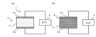
- FIG. 1A is a block diagram of a PM sensor according to an embodiment of the present invention.
- FIG. 1A illustrates a case where the amount of PM is small
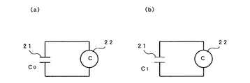
- FIG. FIG. 2A is a model (equivalent circuit) diagram of the PM sensor in FIG. 1
- FIG. 2A shows a time when the amount of PM is small
- FIG. 2B shows a time when the amount of PM is large.
- It is a graph of the rate of change of the amount of PM versus capacitance in the PM sensor of the present invention.
- one PM sensor 1 is provided in a diesel particulate filter (DPF) 3 having a porous filter body 2 partitioned by a number of ceramic partition walls.
- DPF diesel particulate filter
- Two electrodes 4a and 4b forming a capacitor are provided with the above partition interposed therebetween, and the amount of PM collected in the DPF 3 is detected from the capacitance of the capacitor.
- a detection unit for detecting the capacitance of the capacitor formed by the electrodes 4a and 4b and a calculation unit for converting the capacitance to the amount of PM are provided inside the electronic control unit (ECU) 5. It shall be.
- the PM sensor 1 shown in FIG. 1A is modeled as shown in FIG. That is, the capacitance detection unit 22 is connected to a capacitor 21 in which two flat electrodes having the same size are opposed to each other with a predetermined distance between the electrodes.
- FIG. 1B shows that the amount of PM is large by making the hatching of the DPF 3 darker than that in FIG.
- PM model of the sensor 1 the value the capacitance of the capacitor 21 is large as shown in FIG. 2 (b) from the state is a value C 0 low capacitance of the capacitor 21 as shown in FIG. 2 (a) changes to the state is a C 1 (C 1> C 0 ).
- Detecting unit 22 detects the capacitance of capacitor 21. At this time, if the capacitance is C, the dielectric constant of the medium between the electrodes is ⁇ , the area of the electrodes is S, and the distance between the electrodes is d,
- the capacitance C increases as the dielectric constant ⁇ increases or the inter-electrode distance d decreases.
- the present inventors investigated through experiments how the capacitance C of the capacitor formed by the two electrodes 4a and 4b installed in the PM sensor 1 changes depending on the amount of collected PM. It was. That is, by sucking from the downstream of the PM sensor 1, air was flown from the upstream to the downstream, and PM was gradually added into the air upstream of the PM sensor 1, and the change in the capacitance C was recorded. As a result, as shown in FIG. 3, it was found that the capacitance C increased almost linearly with respect to the amount of PM input. That is, the capacitance C accurately indicates the amount of PM collected by the PM sensor 1.
- the reason why the capacitance C increases in proportion to the amount of collected PM is that the conductor carbon is inserted between the electrodes 4a and 4b, so that the inter-electrode distance d is apparently reduced and the capacitance is increased. It is conceivable that C increases or PM increases in the medium between the electrodes 4a and 4b and the dielectric constant ⁇ increases and the capacitance C increases.
- the PM sensor 1 of the present invention two electrodes 4a and 4b that form a capacitor with one or more partition walls interposed in the DPF 3, the capacitance C of the capacitor is captured by the DPF 3.
- the amount of PM collected can be accurately detected. Since the PM sensor 1 of the present invention has a simple configuration in which only the electrodes 4a and 4b are arranged, there are advantages that manufacturing is easy and cost is low.
- the PM sensor 1 detects the amount of PM trapped in the partition wall from the capacitance even if two electrodes 4a and 4b are installed with only one partition wall sandwiched from the operating principle described above. Is done. However, in practice, it is desirable to install the electrodes 4a and 4b so as to sandwich a plurality of partition walls.
- the PM sensor 41 of the present invention is provided with two electrodes 42a and 42b on the outer periphery of the filter main body 43 so as to face each other.
- the filter main body 43 is formed in an elliptic cylinder shape having a predetermined length in the tube axis direction, and one electrode 42 a extends along the upper portion of the filter main body 43 and the other electrode 42 b extends along the lower portion of the filter main body 43. Accordingly, they are provided separately from each other.
- the electrodes 42a and 42b face each other across the entire length in the tube axis direction with the filter main body 43 interposed therebetween.
- the PM sensor 41 can detect a capacitance C proportional to almost the total amount of the collected PM because most of the partition walls constituting the filter body 43 are sandwiched between the electrodes.
Landscapes
- Engineering & Computer Science (AREA)
- Chemical & Material Sciences (AREA)
- Combustion & Propulsion (AREA)
- Mechanical Engineering (AREA)
- General Engineering & Computer Science (AREA)
- Processes For Solid Components From Exhaust (AREA)
- Combined Controls Of Internal Combustion Engines (AREA)
Abstract
簡素な構成で正確にDPFに溜まったPMの量を検出することができるPMセンサを提供する。 多数の隔壁で仕切られた多孔状のフィルタ本体2を有するディーゼルパティキュレートフィルタ(DPF)3に、1個以上の隔壁を挟んでコンデンサを形成する2つの電極4a,4bを設置し、そのコンデンサの静電容量からDPF3に捕集されているPMの量が検出されるようにした。
Description
本発明は、簡素な構成で正確にDPFに溜まったPMの量を検出することができるPMセンサに関する。
ディーゼルエンジンなどの内燃機関を搭載した車両では、内燃機関から大気までの排気ガスの排出流路にディーゼルパティキュレートフィルタ(Diesel Particulate Filter;以下、DPFという)を設置し、排気ガスに含まれるSOF、SOOTなどの粒子状物質(Particurate Matter)を捕集している(以下、これらをPMと総称する)。DPFは、主としてセラミックからなるハニカム細孔状(四角いものを含む)のフィルタにPMを一時的に捕集する部材である。
DPFに捕集されたPMが溜まると背圧が上昇しエンジン特性の低下をきたすため、堆積したPMを燃焼させる。この動作をDPF再生という。DPF再生時には、排気温度を上昇させるための燃料噴射によって排気温度を上昇させ、DPFを昇温することで、DPFに捕集されているPMを燃焼させる。
このとき、DPFにPMが溜まりすぎていると、DPF再生時の熱でDPFが損傷してしまう。DPFにPMが溜まりすぎないうちにDPF再生するために、従来は、正確に堆積量を計測できないので、一般的に安全係数を比較的多く取りDPFを再生している。
しかし、必要以上に短い間隔でDPF再生を実行すると燃料が余分に消費されることになり、燃費が悪化する。したがって、PMの量を正確に検出し、最も適切な時期にDPF再生を行うようにするのが望ましい。
従来、車両の走行距離が所定値に達するごとにDPF再生するようにしたのは、DPFに溜まったPMの量(PMロード;フィルタの詰まり具合を表す)を検出するのが困難であるからである。例えば、特許文献2の技術では、DPFの上流側と下流側の排気ガスの圧力差からPMの量を検出している。しかし、排気の流量・温度は、内燃機関の状態変化に伴ってたえず変化しているため、圧力差から検出するPMの量は正確でない。また、特許文献1では、PMの量を検出するという目的のために、車両走行上に必要のない空燃比変化を与えることになり、好ましくない。
また、実験室において、DPFに溜まったPMの量を検出する分析装置が知られているが、このような分析装置は大規模であり、車両には搭載できない。
そこで、本発明の目的は、上記課題を解決し、簡素な構成で正確にDPFに溜まったPMの量を検出することができるPMセンサを提供することにある。
上記目的を達成するために本発明は、多数の隔壁で仕切られた多孔状のフィルタ本体を有するディーゼルパティキュレートフィルタ(DPF)に、1個以上の上記隔壁を挟んでコンデンサを形成する2つの電極を設置し、上記コンデンサの静電容量から上記DPFに捕集されているPMの量が検出されるようにしたものである。
上記2つの電極を、それぞれ上記フィルタ本体の外周に、互いに対向させて設けてもよい。
本発明によれば、簡素な構成で正確にDPFに溜まったPMの量を検出することができる。
以下、本発明の一実施形態を添付図面に基づいて詳述する。
図1(a)に示されるように、本発明に係るPMセンサ1は、セラミックからなる多数の隔壁で仕切られた多孔状のフィルタ本体2を有するディーゼルパティキュレートフィルタ(DPF)3に、1個以上の隔壁を挟んでコンデンサを形成する2つの電極4a,4bを設置し、そのコンデンサの静電容量からDPF3に捕集されているPMの量が検出されるようにしたものである。
この実施形態では、電子制御装置(ECU)5の内部に電極4a,4bが形成するコンデンサの静電容量を検出する検出部と、静電容量をPMの量に変換する演算部が設けられているものとする。
図1(a)のPMセンサ1は、図2(a)のようにモデル化して示される。すなわち、2つの同寸法平板状の電極を所定の電極間距離を隔てて対向させたコンデンサ21に対し静電容量の検出部22が接続されている。
次に、PMセンサ1の動作を説明する。
図1(a)のようにDPF3に捕集されたPMの量が少ない状態から、徐々にPMの量が増加し、図1(b)のようにDPF3に捕集されたPMの量が多い状態になったとする。図1(b)はDPF3のハッチングを図1(a)より濃くすることでPMの量が多いことを表している。このとき、PMセンサ1のモデルは、図2(a)のようにコンデンサ21の静電容量が小さい値C0である状態から図2(b)のようにコンデンサ21の静電容量が大きい値C1である状態に変化する(C1>C0)。
検出部22では、コンデンサ21の静電容量を検出する。このとき、静電容量をC、電極間の媒体の誘電率をε、電極の面積をS、電極間の距離をdとすると、

となる。よって、誘電率εが大きくなるか電極間距離dが小さくなるかすれば、静電容量Cは大きくなる。
ここで、本発明者らは、PMセンサ1内に設置した2つの電極4a,4bが形成するコンデンサの静電容量Cが捕集されたPMの量によってどのように変化するかを実験により調べた。すなわち、PMセンサ1の下流から吸引することによって上流から下流に空気を流し、そのPMセンサ1の上流において空気中にPMを少量ずつ投入し、静電容量Cの変化を記録した。その結果、図3に示されるように、PMの投入量に対してほぼ直線的に静電容量Cが増大することが分かった。すなわち、静電容量Cは、PMセンサ1に捕集されたPMの量を正確に示す。
静電容量Cが捕集されたPMの量に比例して増加する理由としては、電極4a,4b間に導体である炭素が入ることで、見かけ上、電極間距離dが小さくなり静電容量Cが大きくなる、あるいは、電極4a,4b間の媒体中にPMが増加して誘電率εが大きくなり静電容量Cが大きくなると考えられる。
以上説明したように、本発明のPMセンサ1は、DPF3に、1個以上の隔壁を挟んでコンデンサを形成する2つの電極4a,4bを設置したので、コンデンサの静電容量CからDPF3に捕集されているPMの量を正確に検出することができる。本発明のPMセンサ1は、電極4a,4bを配置するだけの簡素な構成であるため、製造が容易であり、コストが安いという利点がある。
なお、PMセンサ1は、前述した動作原理から、ただ1個の隔壁を挟んで2つの電極4a,4bを設置しても、その隔壁に捕集されているPMの量が静電容量から検出される。しかし、実際には、複数の隔壁を挟むように電極4a,4bを設置するのが望ましい。
次に、本発明の他の実施形態を説明する。
図4に示されるように、本発明のPMセンサ41は、2つの電極42a,42bを、それぞれフィルタ本体43の外周に、互いに対向させて設けたものである。ここでは、フィルタ本体43が管軸方向に所定長の楕円筒形に形成されており、一方の電極42aはフィルタ本体43の上部に沿わせて、他方の電極42bはフィルタ本体43の下部に沿わせて、互いに分離されて設けられている。各電極42a,42bは、管軸方向の全長にわたり、フィルタ本体43を上下に挟んで対向する。
PMセンサ41は、フィルタ本体43を構成する大部分の隔壁が電極間に挟まれるため、捕集されているPMのほぼ全量に比例する静電容量Cを検出することができる。
1,41 PMセンサ
2,43 フィルタ本体
3 ディーゼルパティキュレートフィルタ(DPF)
4a,4b,42a,42b 電極
5 ECU
2,43 フィルタ本体
3 ディーゼルパティキュレートフィルタ(DPF)
4a,4b,42a,42b 電極
5 ECU
Claims (2)
- 多数の隔壁で仕切られた多孔状のフィルタ本体を有するディーゼルパティキュレートフィルタ(DPF)に、1個以上の上記隔壁を挟んでコンデンサを形成する2つの電極を設置し、上記コンデンサの静電容量から上記DPFに捕集されているPMの量が検出されるようにしたことを特徴とするPMセンサ。
- 上記2つの電極を、それぞれ上記フィルタ本体の外周に、互いに対向させて設けたことを特徴とする請求項1記載のPMセンサ。
Applications Claiming Priority (2)
| Application Number | Priority Date | Filing Date | Title |
|---|---|---|---|
| JP2009-141616 | 2009-06-12 | ||
| JP2009141616A JP5625265B2 (ja) | 2009-06-12 | 2009-06-12 | Pmセンサ |
Publications (1)
| Publication Number | Publication Date |
|---|---|
| WO2010143657A1 true WO2010143657A1 (ja) | 2010-12-16 |
Family
ID=43308912
Family Applications (1)
| Application Number | Title | Priority Date | Filing Date |
|---|---|---|---|
| PCT/JP2010/059764 Ceased WO2010143657A1 (ja) | 2009-06-12 | 2010-06-09 | Pmセンサ |
Country Status (2)
| Country | Link |
|---|---|
| JP (1) | JP5625265B2 (ja) |
| WO (1) | WO2010143657A1 (ja) |
Cited By (2)
| Publication number | Priority date | Publication date | Assignee | Title |
|---|---|---|---|---|
| CN105026707A (zh) * | 2013-01-28 | 2015-11-04 | 五十铃自动车株式会社 | 内燃机的排气净化装置 |
| CN105143623A (zh) * | 2013-02-22 | 2015-12-09 | 五十铃自动车株式会社 | 内燃机的排气净化装置 |
Families Citing this family (2)
| Publication number | Priority date | Publication date | Assignee | Title |
|---|---|---|---|---|
| JP2014145277A (ja) * | 2013-01-28 | 2014-08-14 | Isuzu Motors Ltd | 内燃機関の排気浄化装置 |
| JP6705268B2 (ja) * | 2016-04-14 | 2020-06-03 | いすゞ自動車株式会社 | センサ |
Citations (1)
| Publication number | Priority date | Publication date | Assignee | Title |
|---|---|---|---|---|
| WO2008117869A1 (ja) * | 2007-03-28 | 2008-10-02 | Ngk Insulators, Ltd. | 微粒子捕集器のインピーダンス測定器およびインピーダンス測定方法 |
Family Cites Families (2)
| Publication number | Priority date | Publication date | Assignee | Title |
|---|---|---|---|---|
| JP4260345B2 (ja) * | 2000-07-03 | 2009-04-30 | 日産ディーゼル工業株式会社 | ディーゼルエンジンの排気浄化装置 |
| JP2009097410A (ja) * | 2007-10-16 | 2009-05-07 | Toyota Motor Corp | パティキュレートフィルタにおけるpm捕集量推定装置およびフィルタ再生システム |
-
2009
- 2009-06-12 JP JP2009141616A patent/JP5625265B2/ja not_active Expired - Fee Related
-
2010
- 2010-06-09 WO PCT/JP2010/059764 patent/WO2010143657A1/ja not_active Ceased
Patent Citations (1)
| Publication number | Priority date | Publication date | Assignee | Title |
|---|---|---|---|---|
| WO2008117869A1 (ja) * | 2007-03-28 | 2008-10-02 | Ngk Insulators, Ltd. | 微粒子捕集器のインピーダンス測定器およびインピーダンス測定方法 |
Cited By (4)
| Publication number | Priority date | Publication date | Assignee | Title |
|---|---|---|---|---|
| CN105026707A (zh) * | 2013-01-28 | 2015-11-04 | 五十铃自动车株式会社 | 内燃机的排气净化装置 |
| CN105026707B (zh) * | 2013-01-28 | 2017-12-19 | 五十铃自动车株式会社 | 内燃机的排气净化装置 |
| CN105143623A (zh) * | 2013-02-22 | 2015-12-09 | 五十铃自动车株式会社 | 内燃机的排气净化装置 |
| CN105143623B (zh) * | 2013-02-22 | 2017-12-19 | 五十铃自动车株式会社 | 内燃机的排气净化装置 |
Also Published As
| Publication number | Publication date |
|---|---|
| JP5625265B2 (ja) | 2014-11-19 |
| JP2010285958A (ja) | 2010-12-24 |
Similar Documents
| Publication | Publication Date | Title |
|---|---|---|
| JP5540585B2 (ja) | Pmセンサ | |
| JP6459437B2 (ja) | 診断装置及びセンサ | |
| CN105074148B (zh) | 颗粒状物质的测量装置 | |
| JP5625812B2 (ja) | Pmセンサ及びpmセンサ製造方法 | |
| JP6089763B2 (ja) | 粒子状物質の測定装置 | |
| JP6136298B2 (ja) | 内燃機関の排気浄化装置 | |
| WO2016047529A1 (ja) | 診断装置 | |
| CN107076692B (zh) | 传感器 | |
| CN107250496A (zh) | 排气净化装置 | |
| JP5625265B2 (ja) | Pmセンサ | |
| JP5428583B2 (ja) | Pmセンサ | |
| CN105612320B (zh) | 排气净化系统 | |
| US10072551B2 (en) | Exhaust purification system | |
| JP6036388B2 (ja) | 粒子状物質の測定装置 | |
| CN106715850A (zh) | 传感器 | |
| WO2011004747A1 (ja) | Pmセンサ | |
| US10481061B2 (en) | Sensor for detecting an emission amount of particulate matter | |
| CN107709967B (zh) | 粒子状物质传感器及包括其的废气净化系统 | |
| CN106795793A (zh) | 传感器 | |
| WO2014115621A1 (ja) | 内燃機関の排気浄化装置 | |
| JP2016109512A (ja) | センサ及び内燃機関の制御装置 | |
| JP6784050B2 (ja) | センサ | |
| JP6451179B2 (ja) | 診断装置 | |
| JP2016061680A (ja) | センサ |
Legal Events
| Date | Code | Title | Description |
|---|---|---|---|
| 121 | Ep: the epo has been informed by wipo that ep was designated in this application |
Ref document number: 10786188 Country of ref document: EP Kind code of ref document: A1 |
|
| NENP | Non-entry into the national phase |
Ref country code: DE |
|
| 122 | Ep: pct application non-entry in european phase |
Ref document number: 10786188 Country of ref document: EP Kind code of ref document: A1 |