WO2010143497A1 - 動画像データ処理装置、撮像装置および動画像再生装置 - Google Patents
動画像データ処理装置、撮像装置および動画像再生装置 Download PDFInfo
- Publication number
- WO2010143497A1 WO2010143497A1 PCT/JP2010/058186 JP2010058186W WO2010143497A1 WO 2010143497 A1 WO2010143497 A1 WO 2010143497A1 JP 2010058186 W JP2010058186 W JP 2010058186W WO 2010143497 A1 WO2010143497 A1 WO 2010143497A1
- Authority
- WO
- WIPO (PCT)
- Prior art keywords
- moving image
- reliability
- frame
- image data
- interpolation
- Prior art date
- Legal status (The legal status is an assumption and is not a legal conclusion. Google has not performed a legal analysis and makes no representation as to the accuracy of the status listed.)
- Ceased
Links
Images






Classifications
-
- G—PHYSICS
- G09—EDUCATION; CRYPTOGRAPHY; DISPLAY; ADVERTISING; SEALS
- G09G—ARRANGEMENTS OR CIRCUITS FOR CONTROL OF INDICATING DEVICES USING STATIC MEANS TO PRESENT VARIABLE INFORMATION
- G09G5/00—Control arrangements or circuits for visual indicators common to cathode-ray tube indicators and other visual indicators
-
- G—PHYSICS
- G09—EDUCATION; CRYPTOGRAPHY; DISPLAY; ADVERTISING; SEALS
- G09G—ARRANGEMENTS OR CIRCUITS FOR CONTROL OF INDICATING DEVICES USING STATIC MEANS TO PRESENT VARIABLE INFORMATION
- G09G2320/00—Control of display operating conditions
- G09G2320/10—Special adaptations of display systems for operation with variable images
- G09G2320/106—Determination of movement vectors or equivalent parameters within the image
-
- G—PHYSICS
- G09—EDUCATION; CRYPTOGRAPHY; DISPLAY; ADVERTISING; SEALS
- G09G—ARRANGEMENTS OR CIRCUITS FOR CONTROL OF INDICATING DEVICES USING STATIC MEANS TO PRESENT VARIABLE INFORMATION
- G09G2340/00—Aspects of display data processing
- G09G2340/04—Changes in size, position or resolution of an image
- G09G2340/0407—Resolution change, inclusive of the use of different resolutions for different screen areas
- G09G2340/0435—Change or adaptation of the frame rate of the video stream
-
- G—PHYSICS
- G09—EDUCATION; CRYPTOGRAPHY; DISPLAY; ADVERTISING; SEALS
- G09G—ARRANGEMENTS OR CIRCUITS FOR CONTROL OF INDICATING DEVICES USING STATIC MEANS TO PRESENT VARIABLE INFORMATION
- G09G2340/00—Aspects of display data processing
- G09G2340/10—Mixing of images, i.e. displayed pixel being the result of an operation, e.g. adding, on the corresponding input pixels
Definitions
- the present invention relates to a moving image data processing device that generates high-quality moving images from moving image data with a small number of frames, an imaging device including the moving image data processing device, and a moving image reproduction device.
- CRT TVs and plasma TVs display images while instantaneously blinking the light that represents the image (referred to as impulse display), while LCD televisions continue to hold the same image during the frame display period (referred to as hold display). Therefore, there is a problem that a blurred image (called moving image blur) in which the position of the displayed object is shifted from the viewpoint of the person following the object is visually recognized.
- moving image blur a blurred image in which the position of the displayed object is shifted from the viewpoint of the person following the object is visually recognized.
- the moving image blur is improved by increasing the frame rate and shortening the hold display time per frame.
- FIG. 15 is a diagram for explaining a conventional method of generating an interpolation frame.
- a frame positioned temporally after the interpolation frame is a reference frame
- a frame positioned temporally before is a reference frame.
- the base frame is divided into blocks, block matching is performed between each block and the reference frame, and a motion vector mv (solid arrow) is calculated.
- a motion vector estimation method that does not use an interpolation frame is called indirect estimation.
- the value of the motion vector mv calculated here represents the displacement on the reference frame of the object of the block (target block) to be processed on the base frame. Therefore, in an interpolated frame that is located between the base frame and the reference frame in time, it can be estimated that the block is at a position displaced by mv / 2. Therefore, motion compensation (broken arrows) can be performed by generating an interpolation frame by shifting an area corresponding to a block (reference block) on the reference frame by mv / 2.
- an area where the blocks generated on the interpolation frame overlap overlap area
- an area not covered by the block uncovered area
- the pixel values of the overlapping blocks are averaged in the overlap region.
- an interpolation frame is generated by copying the pixel value of the reference frame.
- Interpolated frame generation method by direct estimation As shown in FIG. 16, there is a conventional method in which the position of the interpolated frame is set as a reference frame, and the frame positioned before in time is set as a reference frame. At this time, the interpolation frame (base frame) is divided into blocks, and the positions of two reference frames corresponding to the target block are calculated as motion vectors mv (solid arrows). A method for estimating a motion vector using an interpolation frame as a reference frame is called direct estimation. Then, motion compensation (broken arrows) can be performed by generating an interpolation frame by moving the area corresponding to the reference block on the reference frame by mv.
- a motion vector (high frame rate motion vector) detected using a high frame rate moving image (high frame rate video) having a large inter-frame correlation is transmitted, and the transmitted motion vector is transmitted. And an appropriate interpolated frame is interpolated from the frame image.
- a high frame rate video the possibility of approximating the motion of an object between frames by constant linear motion increases, so that the subjective image quality can be improved by this technique.
- an interpolation frame is generated using a motion vector scheduled to be transmitted on the transmission side, and the corresponding original image is compared. Send the pixel value of the original image instead.
- the failure of the interpolation frame can be avoided.
- Patent Document 1 assumes the movement of an object by a uniform linear motion, correct interpolation is performed for a complex motion in which the object performs a curved motion, a circular motion, or an inconstant motion. Cannot be performed, and the subjective image quality deteriorates, such as the movement of the object becoming awkward. Further, in the technique of Patent Document 2, since an original image is transmitted for a complicated movement of an object, there is a problem that a code amount of encoded data becomes large.
- the present invention has been made in consideration of the above situation, and includes a moving image data processing device that generates high-quality moving images from moving image data with a small number of frames, and the moving image data processing device.
- An object of the present invention is to provide an imaging device and a moving image reproduction device.
- a moving image data processing apparatus divides frame data of moving image data into a plurality of blocks, and each of the blocks from the reference frame data and reference frame data of the moving image data
- a motion detection unit that detects a motion vector and a prediction error with respect to the block
- a reliability generation unit that generates a reliability indicating the reliability of the motion vector with respect to the prediction error of each block, and the reference frame data of the moving image data
- the motion vector and reliability are output.
- the reliability generation unit generates the reliability by any of the following.
- a reliability is generated by a value obtained by quantizing the prediction error.
- the reliability is generated based on the ratio between the activity indicating the complexity of each block and the prediction error.
- the moving image data processing apparatus includes a frame switching unit that outputs moving image data by switching between a reference frame and a reference frame for each frame, and the motion detection unit outputs a reference that is output from the frame switching unit.
- a motion vector and a prediction error are generated from frame data and reference frame data, and the reliability generation unit is configured to generate the reliability based on the motion vector and the prediction error generated by the motion detection unit. Also good.
- the moving image data processing device includes a reliability determination unit that generates an interpolation processing flag for selecting an appropriate interpolation processing method based on the reliability generated by the reliability generation unit, and the moving image An interpolation frame generation unit that generates an interpolation frame between frames of the moving image data by selecting an appropriate interpolation processing method using the image data, the motion vector, and the interpolation processing flag;
- the interpolation processing flag value includes a first value indicating that the reliability is high, a second value indicating that the reliability is low, and a third value indicating that the reliability is extremely low.
- the interpolation frame generation unit applies normal frame interpolation processing when the interpolation processing flag indicates the first value, and applies when the interpolation flag indicates the second value. Applies an interpolation process that corrects pixel values in a region where image quality degradation occurs during interpolation, and applies an interpolation process that corrects the value of a motion vector if the interpolation flag indicates the third value.
- the imaging device may include an imaging device that outputs captured moving image data and the above-described moving image data processing device, and the moving image output by the imaging device to the imaging device.
- An encoder that outputs moving image encoded data obtained by encoding data; and additional information obtained by encoding and multiplexing the motion vector generated by the motion detector and the reliability generated by the reliability generator And an additional information encoding unit.
- the moving image reproduction device may include the above-described moving image data processing device, and the moving image reproduction device includes a decoder that decodes the input moving image encoded data, and the input additional information.
- An additional information decoding unit that performs demultiplexing and decoding and outputs a motion vector and reliability, and the reliability determination unit generates the interpolation processing flag from the reliability decoded by the additional information decoding unit.
- the interpolation frame generation unit is based on the moving image data decoded by the decoder, the motion vector decoded by the additional information decoding unit, and the interpolation processing flag generated by the reliability determination unit,
- An interpolation method may be generated by selecting an appropriate interpolation processing method.
- a high-quality moving image can be generated from moving image data with a small number of frames.
- a moving image data processing device of the present invention mounted on an imaging device and a moving image playback device, a moving image with reduced moving image blur can be displayed on the liquid crystal display device.
- 1 is a block diagram illustrating a configuration of an imaging apparatus according to a first embodiment of the present invention. It is a block diagram which shows the detailed structure of the motion detection part which concerns on 1st embodiment of this invention. It is a figure for demonstrating each term in the frame interpolation process of this invention. It is a flowchart for demonstrating operation
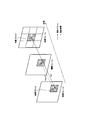
- FIG. 1 is a diagram for explaining the outline of motion vector detection and frame interpolation processing, and shows each frame in the time direction.
- the imaging apparatus sequentially processes captured moving image data as input frames, detects a motion vector corresponding to each input frame, and generates moving image data, a motion vector, and reliability.
- the motion vector and reliability represent a set of motion vectors and reliability between frames of each block obtained by dividing the frame, and are associated with the blocks. Note that the motion vector is detected by the indirect estimation described above, but can be similarly applied even if the direct estimation is used.
- the moving image reproducing apparatus uses the input moving image data as an input frame, and is positioned in the middle of the two input frames in terms of time based on the input frame, the motion vector, and the reliability.
- An interpolation frame to be generated is generated.
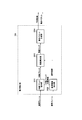
- FIG. 2 is a block diagram illustrating a configuration of the imaging apparatus according to the present embodiment.
- the imaging apparatus 30 includes an imaging element 301, a frame memory 302, a motion detection unit 303, and a reliability generation unit 304. ing. Note that the encoding process is performed on the moving image data, the motion vector, and the reliability output from the imaging apparatus 30. This encoding process will be described in the second embodiment.
- the image sensor 301 is an element that obtains a moving image by converting input optical information into an electric signal, such as a CCD (Charge Coupled Device) or a CMOS (Complementary Metal Oxide Semiconductor).
- the color component of a moving image (input moving image) obtained from the image sensor 301 is generally composed of a plurality of color components such as RGB and YCbCr. In the following description, it is assumed that the color component is a YCbCr component. To do. Further, the image sensor 301 may perform demosaicing and color conversion processing for converting the photoelectric signals spatially thinned for each color component such as a Bayer array into necessary color components and resolution.
- the frame memory 302 can store a plurality of frames, and stores at least the number of frames (2 frames) necessary for estimating a motion vector.
- the frame stored in the frame memory 302 is used as a reference frame and a reference frame by the motion detection unit 303, and further used as a frame for output as moving image data.
- the motion detection unit 303 divides the reference frame into blocks, and detects and outputs motion vectors in units of blocks.
- the color component used in the motion detection unit 303 is a luminance component, and a motion vector is detected by indirect estimation. Further, a residual at the time of block matching in the motion vector detected at the same time is obtained and output as a prediction error.
- the reliability generation unit 304 inputs a reference frame, a motion vector, and a prediction error, and generates a reliability.
- the reliability is output as a value corresponding to each block on the reference frame.
- the reliability is a value obtained by quantifying the probability of the motion vector, and can be calculated, for example, by any of the following.
- the reliability A is a quantized value of the residual of the luminance component used in motion detection.
- This luminance component residual is a prediction error input to the reliability generation unit 304.
- the residual becomes small if the detected motion is reliable, and conversely increases if the detected motion is not accurate, and can be used as a reliability. Also, by performing quantization, it is possible to reduce the code amount of reliability.
- the reliability B is the difference between the reference block extracted from the detected motion vector and the target block with respect to the color component different from the luminance component used for the motion search in the motion detection unit 303, in this embodiment, the color difference component. It is a quantized value.
- the reliability obtained by adding the residual of the luminance component and the color difference component and quantizing may be used.
- the residual of the color difference component is smaller than the residual of the luminance component. Therefore, in order to increase the contribution of the color difference component, a weight (for example, 4 times) may be added.
- the reliability may be obtained by quantizing the larger value of the luminance component residual and the color difference component residual. In this case as well, it is appropriate to weight the residual color difference component.
- the reliability C is a ratio between the activity of the target block and the luminance component residual (prediction error). That is, the ratio of the target blocks is expressed by the following (Formula 1).
- the activity of the target block is the variance (standard deviation) of the pixel values in the block, but it can also be obtained from the absolute difference sum of adjacent pixels in the block, the energy of the AC coefficient in the case of frequency conversion, and the like.
- the smaller the residual of the luminance component and the higher the activity that is, the higher the reliability of the block with the higher activity relative to the residual of the luminance component, while the higher the residual of the luminance component, the higher the activity.
- the smaller the block that is, the lower the activity in the luminance component residual, the lower the reliability, so the relationship (ratio) between the luminance component residual and the activity can be treated as the reliability. It becomes.
- an input moving image captured by the image sensor 301 is input to the motion detection unit 303 and the reliability generation unit 304 and is stored in the frame memory 302.
- the motion detection unit 303 reads frames corresponding to the base frame and the reference frame from the frame memory 302 and detects a motion vector using them. For example, the data is output to an encoder for encoding a motion vector for output to the transmission path and also output to the reliability generation unit 304. In addition, when the motion vector is derived, the calculated prediction error is output to the reliability generation unit 304.
- the reliability generation unit 304 generates a reliability based on the motion vector and the prediction error output from the motion detection unit 303 and, for example, to an encoder for encoding the reliability for output to the transmission path. Output.
- the unit of input and output of the reliability generation unit 304 may be a block, a plurality of blocks, or a frame.
- the motion detection unit 303 and the reliability generation unit 304 can use the same base frame pixel value and reference frame pixel value, thereby reducing the data transfer amount between the frame memory 302 and each unit. can do.
- the imaging apparatus 30 includes a motion vector storage unit and a prediction error storage unit (not shown), and stores the motion vector and the prediction error output from the motion detection unit 303 only in necessary units. deep.
- the imaging device 30 it is possible to generate and output a motion vector and reliability from an input moving image captured by the imaging element 301.
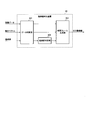
- FIG. 3 is a block diagram showing the configuration of the motion detection unit 303.
- the motion detection unit 303 includes a target block extraction unit 3031, a reference region extraction unit 3032, a residual calculation unit 3033, and a motion vector determination unit 3034. It is composed of
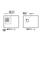
- the target block extraction unit 3031 sequentially outputs the target block obtained by dividing the input reference frame into blocks having a predetermined shape to the residual calculation unit 3033, and refers to the upper left pixel position (referred to as target block position information) of the target block.
- the data are sequentially output to the area extraction unit 3032 (see FIG. 4).
- the block size is preferably 16 ⁇ 16 pixels, which is the macroblock size in general moving picture coding.
- 8 ⁇ 8 or 4 ⁇ 4 is preferable for a video having a small moving area with respect to the image size.
- the block size and the block shape do not have to be uniform, and different sizes and shapes may be used according to the shape of the input moving image. In the following description, it is assumed that the target block is composed only of the luminance component (Y) of the input moving image.
- the reference area extraction unit 3032 reads a reference area on the reference frame corresponding to the input target block position information from the frame memory 302 and outputs the reference area to the residual calculation unit 3033.
- This reference area is a reference required when searching for the input target block in the search range (search range) of the motion vector used by the motion vector determination unit 3034 with the position corresponding to the target block position information as the center.
- the search range is a region of ⁇ 8 pixels on the reference frame centered on the target block position information
- the reference area is an area surrounded by a broken line.
- the residual calculation unit 3033 calculates a residual based on the input target block and the reference region, generates a residual map that is a set of residuals, and outputs the residual map to the motion vector determination unit 3034.
- the residual is calculated using the difference absolute value sum SAD (Sum of Absolute Differences). Other calculation formulas may be used.
- SAD Sum of Absolute Differences
- Other calculation formulas may be used.
- the number of elements in the residual map is the size of the search range.
- the residual between each reference block (size and shape is the same as the target block) in the search range and the target block is recorded corresponding to the position on the search range.
- the motion vector determination unit 3034 determines and outputs a motion vector from the position of the minimum residual in the input residual map and the target block position information. Further, the minimum value in the residual map is output as a prediction error.
- the motion vector detection unit 303 may calculate and output a motion vector and a prediction error in units of blocks, or associates the motion vector and the prediction error generated for each target block with the target block, and a motion vector (not shown)
- the data may be sequentially stored in the storage unit and the prediction error storage unit, and output in a predetermined unit such as a block unit or a frame unit.
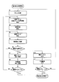
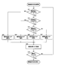
- Step S1 The input reference frame is divided into blocks with a predetermined block size, and the process proceeds to Step S2.
- Step S2 Extract as target blocks sequentially from the upper left block on the reference frame, and simultaneously extract the coordinate position of the target block as target block position information, and proceed to Step S3.
- the following steps S3 to S12 are executed for each target block in the reference frame.
- Step S3 Based on the target block position information and search range parameters (for example, the size of the search range), the search range is determined, the reference area on the reference frame is extracted, and the process proceeds to Step S4.
- the following steps S4 to S6 are executed for each search point within the search range.
- Step S4 A reference block on the reference frame corresponding to each search point in the search range is extracted, and the process proceeds to Step S5.
- Step S5 The residual between the target block and the reference block is calculated, stored in the residual map in association with the search point, and the process proceeds to Step S6.
- Step S6 If it is the last search point, the process proceeds to step S7, the process for the next target block is performed, and if not, the process returns to step S4.
- Step S7 The position of the minimum value of the residual map is extracted as a motion vector, the motion vector information is stored in a motion vector storage unit (not shown), and the process proceeds to Step S8.
- Step S8 The minimum value of the residual map is extracted as a prediction error, the prediction error is stored in a prediction error storage unit (not shown), and the process proceeds to step S9.
- Step S9 If the current block is the last block in a predetermined unit, the process proceeds to step S10. If not, the process returns to step S2, and the process for the next target block is performed.
- Step S10 The stored motion vector is output, and the process proceeds to Step S11.
- the output unit may be a block, a plurality of blocks, or a frame.
- Step S11 The stored prediction error is output, and the process proceeds to Step S12.
- the output unit is the same unit as in step S10.
- Step S12 If the reference frame is the last frame, the process ends. If not, the process returns to step S1, and the process for the next reference frame is performed.
- Step S21 The type of reliability to be generated is selected, and the process proceeds to Step S22.
- the type of reliability may be determined by the processing capability of the imaging device 30 or the type of image, or may be stored in advance in the imaging device 30 in consideration of these. For example, since the process of generating the reliability A is only quantization, the amount of processing is small, so that it can be used for an imaging apparatus with low processing capability.
- the reliability B and the reliability C require a certain amount of processing, they can be used for an imaging apparatus with a medium processing capacity or higher.
- the reliability B is effective for an image in which a color component error is likely to occur.
- the reliability C is effective for an image in which a flat region and a non-flat region are mixed.
- Step S22 If the reliability type is reliability A, the process proceeds to step S23. If the reliability type is reliability B, the process proceeds to step S24. If the reliability type is reliability C, Proceed to step S27.
- Step S23 The input prediction error is quantized to generate a reliability, and the process proceeds to step S30.
- Step S24 A reference block on the reference frame corresponding to the input motion vector is extracted, and the process proceeds to step S25.
- Step S25 The color difference components of the target block and the reference block are extracted, the residual between both blocks is calculated, and the process proceeds to step S26. When there are a plurality of color difference components, a plurality of color difference components are extracted and averaged.
- Step S26 Quantize the residual calculated in step S25, and proceed to step S30.
- Step S27 The luminance component of the target block is extracted, and the process proceeds to Step S28.
- Step S28 The activity is calculated from the distribution of the pixel values of the target block, and the process proceeds to Step S29.
- Step S29 Using the residual (prediction error) corresponding to the target block, the ratio of the residual to the activity is calculated using (Equation 1), and the process proceeds to Step S30.
- Step S30 The calculated reliability is stored in a reliability storage unit (not shown) in association with the target block, and the process proceeds to Step S31.
- Step S31 If the current target block is the last block, the process proceeds to step S32. If not, the process returns to step S22 to perform the process for the next target block.
- Step S32 The stored reliability is output, and the process proceeds to Step S33.
- the unit of output may be any of a block, a plurality of blocks, and a frame, but is the same as the unit output in step S10 of FIG.
- Step S33 If the reference frame is the last frame, the process ends. If not, the process returns to step S21 to perform the process for the next reference frame.
- the quantization in (reliability A) and (reliability B) is uniform quantization with a fixed quantization step width, but non-linear quantization may be used.
- the reliability is preferably quantized so as to have a value of about 4 (2 bits) per block because of the amount of code.
- the step width for dividing the dynamic range of the residual into four equal parts is set. Calculate and quantize.
- the above processing may be performed only for the determined reliability.
- FIG. 7 is a block diagram showing the configuration of the moving image playback apparatus according to the present embodiment.
- the moving image playback apparatus 60 includes a data synchronization unit 601, a reliability determination unit 602, and an interpolation frame generation unit 603. Composed. Note that the moving image data, motion vectors, and reliability output from the imaging device 30 are encoded, but these decoding processes will be described in the second embodiment.
- the data synchronization unit 601 synchronizes the input moving image data, the corresponding motion vector, and the reliability, and outputs the moving image data and the corresponding motion vector to the interpolation frame generation unit 603.
- the reliability is output to the reliability determination unit 602.
- the reliability determination unit 602 determines the magnitude of the input reliability, and sets an interpolation processing flag for selecting an appropriate interpolation processing method according to the reliability from a plurality of predetermined interpolation processing method candidates. And output to the interpolation frame generation unit 603.
- the value of the interpolation processing flag is set to 3 when the reliability is high, 2 or 1 when the reliability is slightly low, and 0 when extremely low, but is not limited to this. Absent.
- the above interpolation processing flag may be switched for each block or each frame.
- the interpolation processing flag is generated for each block. If the interpolation processing method differs for each frame, an interpolation processing flag is generated for each frame.
- the threshold values shown below have a relationship of TH1 ⁇ TH2 ⁇ TH3, and these threshold values are set in advance through experiments or the like.
- Step S41 The target block is sequentially selected from the upper left block on the reference frame, the reliability corresponding to the target block is extracted, and the reliability is compared with the threshold value TH1. If not, the process proceeds to step S43.
- Step S42 It is determined that the reliability is extremely low, the interpolation processing flag 0 is assigned, and the process proceeds to Step S48.
- Step S43 The reliability of the target block is compared with the threshold value TH2, and if it is equal to or less than the threshold value TH2, the process proceeds to step S44, and if not, the process proceeds to step S45.
- Step S44 It is determined that the reliability is slightly low, the interpolation processing flag 1 is assigned, and the process proceeds to Step S48.
- Step S45 The reliability of the target block is compared with the threshold value TH3, and if it is equal to or less than the threshold value TH3, the process proceeds to step S46, and if not, the process proceeds to step S47.
- Step S46 It is determined that the reliability is normal, the interpolation processing flag 2 is assigned, and the process proceeds to Step S48.
- Step S47 It is determined that the reliability of the target block is high, the interpolation processing flag 3 is assigned, and the process proceeds to Step S48.
- Step S48 The assigned interpolation processing flag is stored in an interpolation processing flag storage unit (not shown) in association with the target block, and the process proceeds to Step S49.
- Step S49 If the target block is the last block, the process returns to step S41, and if not, the process ends.
- the interpolation frame generation unit 603 generates and outputs an interpolation frame from the input moving image data, the motion vector, and the interpolation processing flag.
- the method for generating the interpolation frame is changed according to the value of the interpolation processing flag input from the reliability determination unit 602.
- an interpolation frame is generated by any of the following methods.
- the upper / lower / left / right two pixels are expanded and the interpolation is performed with 12 ⁇ 12 pixels.
- the uncovered area in which the interpolation frame is not covered by the block is reduced, so that deterioration of the interpolation frame can be suppressed.
- an average value of overlapping pixel values is used for an overlapping region where blocks overlap on an interpolation frame.
- the motion vector of the target block is corrected using the motion vector of the neighboring peripheral block and interpolated. For example, the median value, average value, or weighted average of motion vectors for a total of 9 blocks (or a total of 25 blocks of 5 ⁇ 5) of 3 ⁇ 3 around the target block is taken as the motion vector of the target block.
- This interpolation method is effective in removing motion vectors that are significantly different from the surrounding motion vectors.
- interpolation methods are not limited to the above methods, and other methods may be used depending on the type of moving image to be handled.
- the data synchronization unit 601 stores the input moving image data, motion vector, and reliability in a buffer (not shown), outputs the reliability to the reliability determination unit 602 at a predetermined timing, and the interpolation processing flag is interpolated.
- the reference frame and the corresponding motion vector are output to the interpolation frame generation unit 603 at the timing output to the frame generation unit 603.
- the interpolation frame generation unit 603 generates an interpolation frame from the moving image data, the motion vector, and the interpolation processing flag according to various interpolation processing flags, and outputs it as an output moving image. If the reliability is slightly low, a relatively accurate motion vector may be detected. However, in the interpolated frame, the deterioration of the motion vector accuracy is likely to cause deterioration such as block distortion. Interpolation processing having the effect of a deblocking filter like the above processing is desirable. On the other hand, when the reliability is extremely low, a motion vector that is completely different from the actual motion may be detected, and deterioration is likely to occur in the interpolation frame. Therefore, as in the process (3) above, the motion A method of correcting the motion vector itself on the assumption that the spatial correlation of the vector is large is desirable.
- interpolation is also performed for a moving image with complicated motion. Frame failure can be suppressed, and the quality of the reproduced moving image is improved. Furthermore, even when a moving image with complicated motion is encoded, a moving image is not included instead of a motion vector, so that the code amount can be suppressed.
- a data encoding portion is added to the imaging device 30 of the first embodiment, and a data decoding portion is added to the moving image reproduction device 60.
- FIG. 9 is a block diagram illustrating a configuration of the imaging apparatus according to the present embodiment.
- the imaging apparatus 30 includes an imaging element 301, a frame memory 302, a motion detection unit 303, a reliability generation unit 304, an encoder 40, and an additional information code. It is comprised from the conversion part 50.
- the encoder 40 and the additional information encoding part 50 are demonstrated, you may provide these as an additional function instead of providing in the imaging device 30.
- the encoder 40 is configured by a known technique, encodes moving image data output from the image sensor 301, and outputs moving image encoded data. It should be noted that an encoder that realizes an improvement in encoding efficiency and a reduction in processing amount by using the motion vector output from the motion detection unit 303 and the reliability output from the reliability generation unit 304 at the time of encoding. Can be used.
- the processing amount of motion search inside the encoder can be greatly reduced. That is, when the reliability is low, there is a possibility of causing an erroneous estimation of the motion vector. Therefore, the erroneous estimation can be suppressed by narrowing the search range. Further, the search range can be changed depending on whether the reliability of the target block is relatively large or small relative to the reliability of the surrounding blocks. Furthermore, when a plurality of prediction vector candidates are set and a search is performed using each prediction vector as a search center point, when a motion vector that gives an index equal to or lower than a predetermined threshold is obtained, the threshold is set according to the reliability. By changing the search and aborting the search, unnecessary searches can be suppressed.
- an appropriate block size can be selected with a small amount of processing. That is, by selecting a large block for a block with high reliability and a small block for a block with low reliability, high encoding efficiency can be achieved with a small amount of processing.
- the additional information encoding unit 50 receives the motion vector output from the motion detection unit 303 and the reliability output from the reliability generation unit 304, encodes and multiplexes each of the motion vector and the reliability, Generate and output additional information.
- FIG. 10 is a block diagram showing a detailed configuration of the additional information encoding unit 50.
- the additional information encoding unit 50 includes a motion vector encoding unit 501, a reliability encoding unit 502, a multiplexing unit. 503.
- the motion vector encoding unit 501 encodes the input motion vector and outputs the motion vector encoded data to the multiplexing unit 503.
- a motion vector encoding method a method generally used for moving image encoding such as variable length encoding is applied to a difference value between an input motion vector and a prediction vector thereof. .
- variable length coding is applied to the difference value between the motion vector of the target block and the prediction vector, and motion vector coded data is output.
- the prediction vector is preferably, for example, the median value of neighboring blocks (left, upper, upper right blocks) of the target block using the spatial correlation of motion vectors.
- the reliability encoding unit 502 encodes the input reliability and outputs the reliability encoded data to the multiplexing unit 503.
- an encoding method there is a method such as variable length encoding for the difference value between the input reliability and the prediction reliability.
- the predicted value for example, the median value of the neighboring blocks of the target block is preferable.
- the multiplexing unit 503 receives the motion vector encoded data output from the motion vector encoding unit 501 and the reliability encoded data output from the reliability encoding unit 502, multiplexes them, and outputs them as additional information. .
- motion vector encoded data and reliability encoded data may be interleaved and output in units of blocks or a plurality of blocks, or one frame of motion vector encoded data and reliability encoding may be output. Data may be output in order.
- moving image encoded data and additional information can be generated from an input moving image and output to a transmission path, a recording medium, or the like.
- FIG. 11 is a block diagram showing the configuration of the moving image playback apparatus according to the present embodiment.
- the moving image playback apparatus 60 includes a decoder 70, an additional information decoding unit 80, a data synchronization unit 601, a reliability determination.
- a unit 602 and an interpolation frame generation unit 603 are included.
- the data synchronization unit 601, the reliability determination unit 602, and the interpolated frame generation unit 603 are the same as those in the first embodiment, and a description thereof will be omitted.
- the decoder 70 and the additional information decoding unit 80 will be described, but these may be provided as an additional function instead of being provided in the moving image reproduction device 60.
- the decoder 70 decodes the moving image encoded data received from the transmission path by a known technique, and outputs the moving image decoded data to the data synchronization unit 601.
- the additional information decoding unit 80 separates and decodes the additional information received from the transmission path, and outputs the motion vector and the reliability to the data synchronization unit 601. As shown in FIG. 12, the additional information decoding unit 80 includes a demultiplexing unit 801, a motion vector decoding unit 802, and a reliability decoding unit 803.
- the demultiplexing unit 801 demultiplexes the additional information received from the transmission path, separates it into encoded motion vector data and reliability encoded data, and outputs the motion vector encoded data to the motion vector decoding unit 802.
- the reliability encoded data is output to the reliability decoding unit 80.
- the motion vector decoding unit 802 receives the encoded motion vector data, performs a decoding process, and outputs a motion vector.
- decoding is performed by a known decoding method corresponding to the encoding method used in the motion vector encoding unit 501.
- the reliability decoding unit 803 receives the reliability encoded data, performs a decoding process, and outputs the reliability.
- decoding is performed by a known decoding method corresponding to the encoding method used in the reliability encoding unit 502.
- a moving image can be reproduced from the encoded moving image data and the additional information input from the transmission path.
- a frame switching unit is added to the imaging device 30 of the second embodiment, and the moving image playback device 60 is the same as that of the second embodiment. Only the differences will be described below.
- FIG. 13 is a block diagram illustrating a configuration of the imaging apparatus according to the present embodiment.
- the imaging apparatus 30 includes an imaging element 301, a frame switching unit 90, a frame memory 302, a motion detection unit 303, and reliability generation. Part 304, encoder 40, and additional information encoding part 50.
- the image sensor 301, the frame memory 302, the motion detection unit 303, the reliability generation unit 304, the encoder 40, and the additional information encoding unit 50 are the same as those in the second embodiment, and the description thereof is omitted.
- the encoder 40 and the additional information encoding unit 50 may be provided as an additional function instead of being provided in the imaging device 30.
- the added frame switching unit 90 and the points changed thereby will be described.
- the frame switching unit 90 classifies the inputted input moving image into a standard frame and a reference frame and outputs them.
- the frame rate of the input moving image and the frame rate of the standard frame are switched to classify the frame into the standard frame and the reference frame.
- the ratio between the frame rate of the input moving image and the frame rate of the reference frame may be any of 1/2, 1/3, 1/4, and the like. In the present embodiment, it is assumed that the ratio is 1 ⁇ 2, and input video images that are sequentially input are switched between the base frame and the reference frame and output every other frame.
- the frame memory 302 stores the reference frame output by the frame switching unit 90.
- the accumulated reference frames are used by the motion detection unit 303, output to the encoder 40 at an appropriate timing, and encoded as moving image data.
- the frame rate of the input moving image is 60 fps
- the frame rate of the base frame and the reference frame is 30 fps.
- a 60 fps input moving image shot by the image sensor 301 is classified into a 30 fps reference frame and a reference frame in the frame switching unit 90, the 30 fps reference frame is stored in the frame memory 302, and the 30 fps reference frame is moved.
- the data is input to the detection unit 303 and the reliability generation unit 304.
- the motion detection unit 303 calls a reference frame corresponding to the base frame from the frame memory 302 and derives a motion vector using them.
- the reliability generation unit 304 generates a reliability from the motion vector output by the motion detection unit 303 and the prediction error and outputs the reliability.
- the encoder 40 encodes the reference frame using the motion vector and the reliability and outputs moving image encoded data.
- the additional information encoding unit 50 outputs additional information obtained by encoding and multiplexing the motion vector and the reliability. These moving image encoded data and additional information are output to the transmission line, and on the display side, the moving image can be reproduced from the moving image encoded data and the additional information by using the moving image reproducing device 60 of the second embodiment. .
- FIG. 14 is a diagram for explaining an outline of processing from moving image input to frame interpolation in the present embodiment, and the horizontal axis indicates the time direction.
- 14A corresponds to the process of detecting a motion vector in the imaging apparatus 30
- FIG. 14B corresponds to the frame interpolation process in the moving image reproduction apparatus 60.
- the imaging device 30 receives a captured 60 fps moving image as an input.
- the input moving image is classified into a base frame and a reference frame every other frame by the frame switching unit 90, the reference frame is encoded and output as moving image encoded data, and between the base frame and the reference frame.
- a motion vector corresponding to the motion is generated and output as additional information together with the reliability.
- the moving image reproduction device 60 reproduces a 60 fps moving image by using each frame of the moving image decoded data obtained by decoding from the encoded moving image data and generating an interpolation frame using the motion vector and the reliability. To do.
- the imaging apparatus of the present embodiment it is possible to output moving image encoded data and additional information from an input moving image. Therefore, when a moving image having a high frame rate is input, more accurate movement is performed. It is possible to detect vectors. Furthermore, by using the moving image reproducing apparatus of the present embodiment, an appropriate interpolation process can be performed on each block based on the reliability determined by the imaging apparatus, so that the image quality is good.
- the present invention is not limited to the above-described embodiment, and various modifications and corrections can be made without departing from the scope of the present invention.
- the moving image data processing apparatus may be configured by the frame memory 302, the motion detection unit 303, and the reliability generation unit 304 described above.
- the encoding device may be composed of the above moving image data processing device, the encoder 40, and the additional information encoding unit 50.
- the image pickup apparatus according to the first embodiment can be configured by combining the moving image data processing apparatus with the image pickup element 301.
- the imaging apparatus of the second embodiment can be configured by combining the above-described encoding apparatus with the imaging element 301.
- the frame rate conversion apparatus may be configured by a data synchronization unit 601, a reliability determination unit 602, and an interpolation frame generation unit 603.
- the decoding device may be composed of the decoder 70, the additional information decoding unit 80, and the above frame rate conversion device.
- the moving image playback device of the first embodiment can be configured by combining the frame rate conversion device with a device that reads a moving image, a motion vector, and reliability and a display device that displays the played back moving image.
- the moving image reproduction apparatus according to the second embodiment is a combination of an apparatus that reads an encoded moving image and encoded additional information, the above-described encoding apparatus, and a display device that displays the reproduced moving image. Can be configured.
- the same moving image and motion vector as in the conventional case are output without generating the reliability.
- the interpolation processing flag may be generated after the reliability is generated before the interpolation frame is generated.
- the interpolation processing flag may be generated directly from the calculated reliability.
- the moving image data processing device is composed of the frame switching unit 90, the frame memory 302, the motion detection unit 303, and the reliability generation unit 304, and the encoding device is added to the moving image data processing device with the encoder 40 and the additional information code. It is good also as a structure which combined the conversion part 50. FIG.
- the imaging apparatus according to the third embodiment can be configured by combining the moving image data processing apparatus with the imaging element 301 or combining the encoding apparatus with the imaging element 301.
- the moving image playback device of the third embodiment can be configured in the same manner as the moving image playback device of the first or second embodiment described above.
- DESCRIPTION OF SYMBOLS 30 ... Imaging device 301 ... Image pick-up element 302 ... Frame memory 303 ... Motion detection part 304 ... Reliability generation part 3031 ... Target block extraction part 3032 ... Reference area extraction part 3033 ... Residual calculation part 3034 ... motion vector determination unit, 3034 ... motion vector determination unit, 40 ... encoder, 50 ... additional information encoding unit, 501 ... motion vector encoding unit, 502 ... reliability encoding unit, 503 ... multiplexing unit, 60 ... moving image Image reproducing device, 601... Data synchronization unit, 602... Reliability determination unit, 603... Interpolation frame generation unit, 70... Decoder, 80 .. additional information decoding unit, 801 .. demultiplexing unit, 802. ... reliability decoding unit, 90 ... frame switching unit.
Landscapes
- Engineering & Computer Science (AREA)
- Physics & Mathematics (AREA)
- Computer Hardware Design (AREA)
- General Physics & Mathematics (AREA)
- Theoretical Computer Science (AREA)
- Liquid Crystal Display Device Control (AREA)
- Television Systems (AREA)
- Control Of Indicators Other Than Cathode Ray Tubes (AREA)
- Controls And Circuits For Display Device (AREA)
- Compression Or Coding Systems Of Tv Signals (AREA)
Abstract
フレーム数の少ない動画像データから高画質な動画像を生成する動画像データ処理装置を提供する。動画像データのフレームを複数のブロックに分割し、前記動画像データの基準フレームと参照フレームとから、前記各ブロックに対する動きベクトルと予測誤差を検出する動き検出部と、前記各ブロックの予測誤差に対する動きベクトルの確からしさを示す信頼度を生成する信頼度生成部と、前記信頼度生成部で生成されたブロックごとの信頼度に基づいて、適切な補間処理方法を選択するための補間処理フラグを算出し、生成する信頼度判定部と、前記動画像データと前記動きベクトルと前記補間処理フラグを用いて、適切な補間処理方法を選択して前記動画像データのフレーム間に補間フレームを生成する補間フレーム生成部と、を備える。
Description
本発明は、フレーム数の少ない動画像データから高画質の動画像を生成する動画像データ処理装置、当該動画像データ処理装置を備えた撮像装置および動画像再生装置に関する。
ブラウン管テレビやプラズマテレビは、映像を表現する光を瞬間的に点滅させながら映像を表現(インパルス表示という)するが、液晶テレビは、フレーム表示期間中は同じ映像を保持し続ける(ホールド表示という)ので、物体を追随する人の視点と表示される物体との位置がずれてぼけた画像(動画像ボケという)が視認されるという問題点がある。
したがって、特に、フレーム数の少ない動画像を液晶テレビのような表示装置に表示した場合、動画像ボケが生じ高画質感が得られないという結果となる。
この問題点に対して、液晶テレビでは、例えば、フレームレートを上げて1フレーム当たりのホールド表示時間を短くして、動画像ボケを改善している。
この問題点に対して、液晶テレビでは、例えば、フレームレートを上げて1フレーム当たりのホールド表示時間を短くして、動画像ボケを改善している。
この補間フレームを生成する従来の方法としては、次のような方法がある。
(1)間接推定による補間フレーム生成方法:
図15は、従来の補間フレームの生成方法を説明するための図である。ここでは、補間フレームに対し時間的に後に位置するフレームを基準フレーム、時間的に前に位置するフレームを参照フレームとする。
(1)間接推定による補間フレーム生成方法:
図15は、従来の補間フレームの生成方法を説明するための図である。ここでは、補間フレームに対し時間的に後に位置するフレームを基準フレーム、時間的に前に位置するフレームを参照フレームとする。
まず、基準フレームをブロック分割し、各ブロックと参照フレームの間でブロックマッチングを行い、動きベクトルmv(実線矢印)を算出する。このような、補間フレームを用いない動きベクトル推定方法を間接推定という。
ここで算出した動きベクトルmvの値は、基準フレーム上の処理対象となるブロック(対象ブロック)の物体の、参照フレーム上での変位を表す。したがって、時間的に基準フレームと参照フレームの中間に位置する補間フレームでは、同ブロックはmv/2変位した位置にあると推定できる。
そこで、参照フレーム上のブロック(参照ブロック)に相当する領域をmv/2変位させて補間フレームを生成することで、動き補償(破線矢印)を行うことができる。
そこで、参照フレーム上のブロック(参照ブロック)に相当する領域をmv/2変位させて補間フレームを生成することで、動き補償(破線矢印)を行うことができる。
上記の処理を基準フレームの全てのブロックに対して適用した場合、補間フレーム上に生成されたブロックが重複する領域(オーバラップ領域)と、前記ブロックでカバーされない領域(アンカバード領域)が生じることがある。その場合は、オーバーラップ領域では、重複したブロックの画素値を平均する。また、アンカバード領域では、参照フレームの画素値をコピーすることで、補間フレームを生成する。
(2)直接推定による補間フレーム生成方法:
図16のように補間フレームの位置を基準フレームとし、時間的に前に位置するフレームを参照フレームとする従来手法もある。このとき、補間フレーム(基準フレーム)をブロック分割し、対象ブロックに対応する2つの参照フレームの位置を動きベクトルmv(実線矢印)として算出する。このように、補間フレームを基準フレームとし動きベクトルを推定する方法を直接推定という。そして、参照フレーム上の参照ブロックに相当する領域をmv変位させて補間フレームを生成することで、動き補償(破線矢印)を行うことができる。
図16のように補間フレームの位置を基準フレームとし、時間的に前に位置するフレームを参照フレームとする従来手法もある。このとき、補間フレーム(基準フレーム)をブロック分割し、対象ブロックに対応する2つの参照フレームの位置を動きベクトルmv(実線矢印)として算出する。このように、補間フレームを基準フレームとし動きベクトルを推定する方法を直接推定という。そして、参照フレーム上の参照ブロックに相当する領域をmv変位させて補間フレームを生成することで、動き補償(破線矢印)を行うことができる。
特許文献1の動画像補間装置では、フレーム間相関が大きい高フレームレートの動画像(高フレームレート映像)を用いて検出した動きベクトル(高フレームレート動きベクトル)を送出し、伝送された動きベクトルとフレーム画像とから適切な補間フレームを内挿している。高フレームレート映像では、フレーム間の物体の動きを等速直線運動で近似できる可能性が高まるため、当該技術により主観画質を向上できる。
また、特許文献2の画像信号復号化装置では、送信側で送出する予定の動きベクトルを用いて補間フレームを生成し、それと対応する原画像を比較し、残差が大きい領域については動きベクトルではなく原画像の画素値を送る。この方法では、等速直線運動の仮定が成立しない領域に対しては、原画像の画素値を送るため、補間フレームの破綻を避けることができる。
しかし、特許文献1の技術では、等速直線運動による物体の移動を仮定しているため、物体が曲線運動や円運動、非等速運動を行うような複雑な動きに対しては、正しい補間ができず、物体の動きがぎこちなくなるなどの主観画質の劣化が生じる。
また、特許文献2の技術では、物体が複雑な動きに対しては原画像を送出するため、符号化データの符号量が大きくなることが問題となる。
また、特許文献2の技術では、物体が複雑な動きに対しては原画像を送出するため、符号化データの符号量が大きくなることが問題となる。
本発明は、上記のような実情を考慮してなされたものであって、フレーム数の少ない動画像データから高画質な動画像を生成する動画像データ処理装置、当該動画像データ処理装置を備えた撮像装置および動画像再生装置を提供することを目的とする。
上記課題を解決するために、本発明の動画像データ処理装置は、動画像データのフレームデータを複数のブロックに分割し、前記動画像データの基準フレームデータと参照フレームデータとから、前記各ブロックに対する動きベクトルと予測誤差を検出する動き検出部と、前記各ブロックの予測誤差に対する動きベクトルの確からしさを示す信頼度を生成する信頼度生成部と、を備え、前記動画像データの基準フレームデータ、並びに、前記動きベクトルおよび信頼度を出力する。
前記信頼度生成部は、次のいずれかによって信頼度を生成する。
(1)前記予測誤差を量子化した値により信頼度を生成する。
(2)前記動き検出部で検出した動きベクトルにより関連付けられる参照ブロックと対象ブロックから得られる、前記動き検出に使った成分とは異なる色成分における予測誤差を量子化した値を少なくとも用いて信頼度を生成する。
(3)各ブロックの複雑さを示すアクティビティと前記予測誤差との比により信頼度を生成する。
(1)前記予測誤差を量子化した値により信頼度を生成する。
(2)前記動き検出部で検出した動きベクトルにより関連付けられる参照ブロックと対象ブロックから得られる、前記動き検出に使った成分とは異なる色成分における予測誤差を量子化した値を少なくとも用いて信頼度を生成する。
(3)各ブロックの複雑さを示すアクティビティと前記予測誤差との比により信頼度を生成する。
また、上記の動画像データ処理装置は、動画像データを、フレーム毎に基準フレームと参照フレームに切り替えて出力するフレーム切替部を備え、前記動き検出部は、前記フレーム切替部から出力される基準フレームデータと参照フレームデータから動きベクトルと予測誤差を生成し、前記信頼度生成部は、前記動き検出部で生成した動きベクトルと予測誤差に基づいて、前記信頼度を生成するように構成してもよい。
さらに、上記の動画像データ処理装置は、前記信頼度生成部で生成された信頼度に基づいて、適切な補間処理方法を選択するための補間処理フラグを生成する信頼度判定部と、前記動画像データと前記動きベクトルと前記補間処理フラグを用いて、適切な補間処理方法を選択して前記動画像データのフレーム間に補間フレームを生成する補間フレーム生成部と、を備えている。
ここで、前記補間処理フラグの値には、信頼度が高いことを示す第一の値、信頼度が低い場合を示す第二の値、信頼度が極端に低い場合を示す第三の値が少なくとも含まれており、前記補間フレーム生成部は、前記補間処理フラグが前記第一の値を示す場合には通常のフレーム補間処理を適用し、前記補間フラグが前記第二の値を示す場合には補間時に画質劣化が発生する領域の画素値を修正する補間処理を適用し、前記補間フラグが前記第三の値を示す場合には、動きベクトルの値を修正する補間処理を適用する。
さらにまた、撮像装置を、撮影した動画像データを出力する撮像素子と、上記の動画像データ処理装置とを備えたものとしてもよく、また、この撮像装置に、前記撮像素子が出力する動画像データを符号化した動画像符号化データを出力するエンコーダと、前記動き検出部で生成された動きベクトルおよび前記信頼度生成部で生成された信頼度をそれぞれ符号化して多重化した付加情報を出力する付加情報符号化部と、を備えるものとしてもよい。
また、動画像再生装置を上記の動画像データ処理装置を備えるものとしてもよく、また、この動画像再生装置に、入力された動画像符号化データを復号するデコーダと、入力された付加情報を逆多重化して復号し、動きベクトルおよび信頼度を出力する付加情報復号部と、を備えさせ、前記信頼度判定部は、前記付加情報復号部で復号された信頼度から前記補間処理フラグを生成し、前記補間フレーム生成部は、前記前記デコーダで復号された動画像データと、前記付加情報復号部で復号された動きベクトルと、前記信頼度判定部で生成された補間処理フラグに基づいて、適切な補間処理方法を選択して補間フレームを生成するようにしてもよい。
本発明によれば、フレーム数の少ない動画像データから高画質な動画像を生成することができる。
また、本発明の動画像データ処理装置を撮像装置および動画像再生装置に搭載することによって、液晶表示装置に動画像ボケを抑制した動画像を表示することができる。
また、本発明の動画像データ処理装置を撮像装置および動画像再生装置に搭載することによって、液晶表示装置に動画像ボケを抑制した動画像を表示することができる。
以下、図面を参照して本発明の動画像データ処理装置、撮像装置および動画像再生装置に係る実施形態について説明する。
<第一の実施形態>
本実施形態におけるフレーム補間処理の概略を説明する。
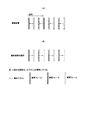
図1は、動きベクトルの検出とフレーム補間の処理の概略を説明するための図であり、時間方向に各フレームを示したものである。
図1(A)のように、撮像装置は、撮影した動画像データを入力フレームとして順次処理し、各入力フレームに相当する動きベクトルを検出し、動画像データ、動きベクトル、信頼度を生成し、出力する。この動きベクトルおよび信頼度は、フレームを分割した各ブロックのフレーム間の動きベクトルおよび信頼度の集合を表し、それぞれブロックと対応付けられている。尚、動きベクトルは、前述した間接推定により検出するが、直接推定を用いても同様に適用することができる。
本実施形態におけるフレーム補間処理の概略を説明する。
図1は、動きベクトルの検出とフレーム補間の処理の概略を説明するための図であり、時間方向に各フレームを示したものである。
図1(A)のように、撮像装置は、撮影した動画像データを入力フレームとして順次処理し、各入力フレームに相当する動きベクトルを検出し、動画像データ、動きベクトル、信頼度を生成し、出力する。この動きベクトルおよび信頼度は、フレームを分割した各ブロックのフレーム間の動きベクトルおよび信頼度の集合を表し、それぞれブロックと対応付けられている。尚、動きベクトルは、前述した間接推定により検出するが、直接推定を用いても同様に適用することができる。
図1(B)のように、動画像再生装置は、入力された動画像データを入力フレームとし、入力フレーム、動きベクトルおよび信頼度に基づいて、時間的に2枚の入力フレームの中間に位置する補間フレームを生成する。
(撮像装置の構成)
まず、本実施形態に係る撮像装置の構成について説明する。
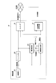
図2は、本実施形態に係る撮像装置の構成を示すブロック図であり、同図において、撮像装置30は、撮像素子301、フレームメモリ302、動き検出部303、信頼度生成部304から構成されている。尚、撮像装置30より出力される動画像データ、動きベクトル、信頼度に対して符号化処理を行うが、この符号化処理については第二の実施形態にて説明する。
まず、本実施形態に係る撮像装置の構成について説明する。
図2は、本実施形態に係る撮像装置の構成を示すブロック図であり、同図において、撮像装置30は、撮像素子301、フレームメモリ302、動き検出部303、信頼度生成部304から構成されている。尚、撮像装置30より出力される動画像データ、動きベクトル、信頼度に対して符号化処理を行うが、この符号化処理については第二の実施形態にて説明する。
撮像素子301は、CCD(Charge Coupled Device)やCMOS(Complementary Metal Oxide Semiconductor)など、入力された光学的な情報を電気信号に変換し、動画像を得る素子である。撮像素子301から得られる動画像(入力動画像)の色成分は、RGB、YCbCrなど、複数の色成分から構成されることが一般的であるが、以下の説明では、YCbCr成分であるとして説明する。また、撮像素子301では、ベイヤ配列のような色成分ごとに空間的に間引かれた光電信号から、必要な色成分、解像度に変換するデモザイキングおよび色変換処理を行っても良い。
フレームメモリ302は、複数枚のフレームを蓄積可能であり、少なくとも動きベクトルを推定する際に必要なフレーム数(2フレーム)を蓄積する。また、フレームメモリ302に蓄積されるフレームは、動き検出部303で基準フレーム、参照フレームとして利用され、さらに、動画像データとして出力するためのフレームとしても利用される。
動き検出部303は、詳細は後述するが、基準フレームをブロックに分割し、動きベクトルをブロック単位で検出し出力する。この動き検出部303で使用する色成分は、輝度成分とし、間接推定で動きベクトルを検出する。また、同時に検出した動きベクトルにおけるブロックマッチング時の残差を求め、予測誤差として出力する。
信頼度生成部304は、詳細は後述するが、基準フレーム、動きベクトルおよび予測誤差を入力し、信頼度を生成する。信頼度は、基準フレーム上の各ブロックに対応した値として出力される。信頼度は、動きベクトルの確からしさを定量化した値であり、例えば、以下のいずれかにより算出できる。
(信頼度A)
信頼度Aは、動き検出の際に使用する輝度成分の残差の量子化値である。この輝度成分の残差は、信頼度生成部304に入力される予測誤差である。
残差は、検出した動きが確からしければ小さくなり、逆に検出した動きが確からしくなければ大きくなるため、信頼度として用いることができる。また、量子化を行うことにより、信頼度の符号量を削減することが可能である。
信頼度Aは、動き検出の際に使用する輝度成分の残差の量子化値である。この輝度成分の残差は、信頼度生成部304に入力される予測誤差である。
残差は、検出した動きが確からしければ小さくなり、逆に検出した動きが確からしくなければ大きくなるため、信頼度として用いることができる。また、量子化を行うことにより、信頼度の符号量を削減することが可能である。
(信頼度B)
信頼度Bは、動き検出部303での動き探索に用いた輝度成分とは異なる色成分、本実施形態では色差成分に対し、検出した動きベクトルから抽出される参照ブロックと対象ブロックの残差の量子化値である。
補間フレームを生成した際に、あるブロックにおいて色差成分の残差が大きければ、各色成分の画素位置のずれ(色ずれ)による画質劣化が懸念される。
したがって、色差成分の残差が大きければ信頼度が低く、小さければ信頼度が高いとして扱うことが可能である。
信頼度Bは、動き検出部303での動き探索に用いた輝度成分とは異なる色成分、本実施形態では色差成分に対し、検出した動きベクトルから抽出される参照ブロックと対象ブロックの残差の量子化値である。
補間フレームを生成した際に、あるブロックにおいて色差成分の残差が大きければ、各色成分の画素位置のずれ(色ずれ)による画質劣化が懸念される。
したがって、色差成分の残差が大きければ信頼度が低く、小さければ信頼度が高いとして扱うことが可能である。
尚、色差成分は、CbとCrの2つが存在するが、いずれかの色成分のみを用いることもできるし、2つの成分の組み合わせ(例えば平均値)を用いてもよい。
また、輝度成分と色成分の両方を用いると、よりノイズに頑健になるため好適である。例えば、輝度成分と色差成分の残差を足して量子化したものを信頼度としてもよい。
一般に、色差成分の残差は、輝度成分の残差よりも小さいものとなるため、色差成分の寄与を強めるために、重みをつけて(例えば、4倍)足し合わせてもよい。また、輝度成分の残差と色差成分の残差の大きい方の値を量子化したものを信頼度としてもよい。この際も、色差成分の残差には重みをつけることが適当である。
また、輝度成分と色成分の両方を用いると、よりノイズに頑健になるため好適である。例えば、輝度成分と色差成分の残差を足して量子化したものを信頼度としてもよい。
一般に、色差成分の残差は、輝度成分の残差よりも小さいものとなるため、色差成分の寄与を強めるために、重みをつけて(例えば、4倍)足し合わせてもよい。また、輝度成分の残差と色差成分の残差の大きい方の値を量子化したものを信頼度としてもよい。この際も、色差成分の残差には重みをつけることが適当である。
(信頼度C)
信頼度Cは、対象ブロックのアクティビティと輝度成分の残差(予測誤差)との比である。即ち、対象ブロックの比は以下の(式1)で表わされる。
信頼度Cは、対象ブロックのアクティビティと輝度成分の残差(予測誤差)との比である。即ち、対象ブロックの比は以下の(式1)で表わされる。
(比)=(アクティビティ)/(輝度成分の残差(予測誤差)) …(式1)
ここで、対象ブロックのアクティビティは、ブロック内の画素値の分散(標準偏差)とするが、ブロック内隣接画素の絶対差分和、周波数変換した場合のAC係数のエネルギーなどによっても求めることができる。
上記の比が信頼度となり得る理由は以下の通りである。
平坦領域を含むブロックではアクティビティ(画素値の分散値)は低くなり、ブロック内に特徴点が存在しないため、動きベクトルの誤推定を招きやすい。
一方、非平坦領域のブロックではアクティビティ(画素値の分散値)は高くなり、ブロック内に特徴点が存在するため、正確な動きベクトルを検出しやすい。
平坦領域を含むブロックではアクティビティ(画素値の分散値)は低くなり、ブロック内に特徴点が存在しないため、動きベクトルの誤推定を招きやすい。
一方、非平坦領域のブロックではアクティビティ(画素値の分散値)は高くなり、ブロック内に特徴点が存在するため、正確な動きベクトルを検出しやすい。
よって、輝度成分の残差が小さく、アクティビティが高いブロックであるほど、つまり輝度成分の残差に対して、アクティビティが大きいブロックでは信頼度は高くなり、一方、輝度成分の残差が高く、アクティビティが小さいブロックであるほど、つまり、輝度成分の残差に対してアクティビティが低いブロックでは信頼度は低いといえるため、輝度成分の残差とアクティビティの関係(比)を信頼度として扱うことが可能となる。
これらの信頼度の生成方法は、上記の方法に限定されるものではなく、その他の手法を用いても良い。また、信頼度の種類は上記の3種類に限らず、何種類でも良い。
(撮像装置30の動作)
次に、本実施形態に係る撮像装置30の動作について説明する。
まず、撮像素子301により撮影された入力動画像は、動き検出部303および信頼度生成部304に入力されるとともに、フレームメモリ302に蓄積される。
次に、本実施形態に係る撮像装置30の動作について説明する。
まず、撮像素子301により撮影された入力動画像は、動き検出部303および信頼度生成部304に入力されるとともに、フレームメモリ302に蓄積される。
次に、動き検出部303は、フレームメモリ302から基準フレームおよび参照フレームに相当するフレームを読み取り、それらを用いて動きベクトルを検出する。例えば、伝送路へ出力するために動きベクトルを符号化するためのエンコーダへ出力するとともに信頼度生成部304に出力する。
また、動きベクトルを導出する際に、算出された予測誤差を信頼度生成部304に出力する。
また、動きベクトルを導出する際に、算出された予測誤差を信頼度生成部304に出力する。
次に、信頼度生成部304は、動き検出部303が出力した動きベクトルおよび予測誤差に基づいて信頼度を生成して、例えば伝送路へ出力するために信頼度を符号化するためのエンコーダへ出力する。
信頼度生成部304の入力及び出力の単位は、ブロック、複数ブロック単位、フレームのいずれでも構わない。ブロック単位とする場合には、動き検出部303と信頼度生成部304で同じ基準フレームの画素値、参照フレームの画素値を用いることができるため、フレームメモリ302と各部間のデータ転送量を削減することができる。
複数ブロック単位もしくはフレーム単位とする場合には、図示しない動きベクトル格納部、予測誤差格納部を撮像装置30に備え、動き検出部303が出力した動きベクトルおよび予測誤差を必要な単位だけ格納しておく。
複数ブロック単位もしくはフレーム単位とする場合には、図示しない動きベクトル格納部、予測誤差格納部を撮像装置30に備え、動き検出部303が出力した動きベクトルおよび予測誤差を必要な単位だけ格納しておく。
以上、説明した通り、撮像装置30を用いることで、撮像素子301で撮影した入力動画像から、動きベクトルおよび信頼度を生成し、出力できる。
(動き検出部303の構成)
次に、動き検出部303の詳細な構成について説明する。
図3は、動き検出部303の構成を示すブロック図であり、同図において、動き検出部303は、対象ブロック抽出部3031、参照領域抽出部3032、残差算出部3033、動きベクトル決定部3034から構成されている。
次に、動き検出部303の詳細な構成について説明する。
図3は、動き検出部303の構成を示すブロック図であり、同図において、動き検出部303は、対象ブロック抽出部3031、参照領域抽出部3032、残差算出部3033、動きベクトル決定部3034から構成されている。
対象ブロック抽出部3031は、入力された基準フレームを所定形状のブロックに分割した対象ブロックを残差算出部3033に順次出力するとともに、対象ブロックの左上の画素位置(対象ブロック位置情報という)を参照領域抽出部3032に順次出力する(図4参照)。
尚、ブロックのサイズは、一般的な動画像符号化におけるマクロブロックサイズの16×16画素が好ましい。但し、画像サイズに対して動領域が小さい映像では、8×8や4×4が好ましい。また、ブロックのサイズおよびブロックの形状は、一様である必要はなく、入力動画像の形状に応じて異なるサイズ、形状を用いても良い。尚、以下の説明では、対象ブロックは、入力動画像の輝度成分(Y)のみから構成されるものとして説明する。
参照領域抽出部3032は、入力された対象ブロック位置情報に応じた参照フレーム上の参照領域を、フレームメモリ302から読み出して残差算出部3033に出力する。
この参照領域は、入力された対象ブロックに対して、対象ブロック位置情報に相当する位置を中心として、動きベクトル決定部3034で用いる動きベクトルの探索範囲(サーチレンジ)で探索する際に必要な参照フレーム内の領域をいう。探索範囲(サーチレンジ)のサイズには、予め決められた固定値を使用するが、フレーム毎や、ブロック毎に適応的に切り替えてもよい。
この参照領域は、入力された対象ブロックに対して、対象ブロック位置情報に相当する位置を中心として、動きベクトル決定部3034で用いる動きベクトルの探索範囲(サーチレンジ)で探索する際に必要な参照フレーム内の領域をいう。探索範囲(サーチレンジ)のサイズには、予め決められた固定値を使用するが、フレーム毎や、ブロック毎に適応的に切り替えてもよい。
図4に示した通り、探索範囲(サーチレンジ)のサイズが8画素の場合は、探索範囲(サーチレンジ)は、対象ブロック位置情報を中心とした参照フレーム上の±8画素の領域であり、参照領域は破線で囲まれた領域となる。
残差算出部3033は、入力された対象ブロックと参照領域に基づいて残差を算出し、残差の集合である残差マップを生成して動きベクトル決定部3034に出力する。残差の算出は、差分絶対値和SAD(Sum of Absolute Differences)を用いて行うが、差分自乗和SSD(Sum of Squared Differences)、変換後差分絶対値和SATD(Sum of Absolute Transformed Differences)等の他の算出式を用いてもよい。残差マップの要素数は、探索範囲の大きさになる。探索範囲内の各参照ブロック(サイズと形状は対象ブロックと同じ)と対象ブロックとの残差が探索範囲上の位置と対応して記録される。
動きベクトル決定部3034は、入力した残差マップ中の最小の残差の位置と対象ブロック位置情報とから動きベクトルを決定し出力する。
また、残差マップ内の最小値を予測誤差として出力する。
動きベクトル検出部303は、ブロック単位で動きベクトルおよび予測誤差を算出し出力しても構わないし、各対象ブロックに対して生成した動きベクトルおよび予測誤差を対象ブロックと対応付けて、図示しない動きベクトル格納部および予測誤差格納部に順次格納し、ブロックを組にした単位やフレーム単位など所定の単位で出力しても構わない。
また、残差マップ内の最小値を予測誤差として出力する。
動きベクトル検出部303は、ブロック単位で動きベクトルおよび予測誤差を算出し出力しても構わないし、各対象ブロックに対して生成した動きベクトルおよび予測誤差を対象ブロックと対応付けて、図示しない動きベクトル格納部および予測誤差格納部に順次格納し、ブロックを組にした単位やフレーム単位など所定の単位で出力しても構わない。
(動き検出部303の動作)
次に、動き検出部303が、入力された基準フレームおよびフレームメモリ上に記録されている参照フレームに基づいて、予測誤差ならびに動きベクトルを導出する動作を図5のフローチャートを用いて説明する。
次に、動き検出部303が、入力された基準フレームおよびフレームメモリ上に記録されている参照フレームに基づいて、予測誤差ならびに動きベクトルを導出する動作を図5のフローチャートを用いて説明する。
(ステップS1)入力された基準フレームを予め定められたブロックサイズによりブロック分割を行い、ステップS2に進む。
(ステップS2)基準フレーム上の左上のブロックから順に対象ブロックとして抽出し、同時に対象ブロックの座標位置を対象ブロック位置情報として抽出し、ステップS3に進む。基準フレーム内の各対象ブロックに対して、以降のステップS3~ステップS12の処理が実行される。
(ステップS2)基準フレーム上の左上のブロックから順に対象ブロックとして抽出し、同時に対象ブロックの座標位置を対象ブロック位置情報として抽出し、ステップS3に進む。基準フレーム内の各対象ブロックに対して、以降のステップS3~ステップS12の処理が実行される。
(ステップS3)対象ブロック位置情報および探索範囲のパラメータ(例えば、探索範囲のサイズ等)に基づいて、探索範囲を決定し、参照フレーム上の参照領域を抽出し、ステップS4に進む。探索範囲内の各探索点に対して、以降のステップS4~ステップS6の処理が実行される。
(ステップS4)探索範囲内の各探索点に対応する参照フレーム上の参照ブロックを抽出し、ステップS5に進む。
(ステップS5)対象ブロックと参照ブロック間の残差を算出し、探索点に対応付けて残差マップへ格納し、ステップS6に進む。
(ステップS6)最後の探索点であれば、ステップS7へ進み、次の対象ブロックに対する処理を行い、そうでなければ、ステップS4に戻る。
(ステップS5)対象ブロックと参照ブロック間の残差を算出し、探索点に対応付けて残差マップへ格納し、ステップS6に進む。
(ステップS6)最後の探索点であれば、ステップS7へ進み、次の対象ブロックに対する処理を行い、そうでなければ、ステップS4に戻る。
(ステップS7)残差マップの最小値の位置を動きベクトルとして抽出し、動きベクトルの情報を図示しない動きベクトル格納部に格納し、ステップS8へ進む。
(ステップS8)残差マップの最小値を予測誤差として抽出し、予測誤差を図示しない予測誤差格納部に格納し、ステップS9へ進む。
(ステップS9)現在のブロックが所定の単位の最後のブロックであれば、ステップS10へ進み、そうでなければ、ステップS2へ戻り、次の対象ブロックに対する処理を行う。
(ステップS8)残差マップの最小値を予測誤差として抽出し、予測誤差を図示しない予測誤差格納部に格納し、ステップS9へ進む。
(ステップS9)現在のブロックが所定の単位の最後のブロックであれば、ステップS10へ進み、そうでなければ、ステップS2へ戻り、次の対象ブロックに対する処理を行う。
(ステップS10)格納された動きベクトルを出力し、ステップS11へ進む。尚、出力の単位は、ブロック、複数ブロック、フレームのいずれでも構わない。
(ステップS11)格納された予測誤差を出力し、ステップS12へ進む。出力の単位は、ステップS10と同じ単位で出力する。
(ステップS12)基準フレームが最後のフレームであれば、処理を終了し、そうでなければステップS1へ戻り、次の基準フレームに対する処理を行う。
(ステップS11)格納された予測誤差を出力し、ステップS12へ進む。出力の単位は、ステップS10と同じ単位で出力する。
(ステップS12)基準フレームが最後のフレームであれば、処理を終了し、そうでなければステップS1へ戻り、次の基準フレームに対する処理を行う。
(信頼度生成部304の動作)
次に、入力された予測誤差および動きベクトルに基づいて、信頼度を導出する信頼度生成部304の動作を図6のフローチャートを用いて説明する。
次に、入力された予測誤差および動きベクトルに基づいて、信頼度を導出する信頼度生成部304の動作を図6のフローチャートを用いて説明する。
(ステップS21)生成する信頼度の種類を選択し、ステップS22に進む。
ここで、信頼度の種類は、撮像装置30の処理能力もしくは画像の種類によって決定するか、これらを考慮して撮像装置30内に予め記憶させておいてもよい。
例えば、信頼度Aの生成処理は量子化のみであるため処理量が少ないので、処理能力の低い撮像装置のときに使える。一方、信頼度Bや信頼度Cは多少の処理量が必要となるため、処理能力が中程度以上の撮像装置のときに使える。また、輝度成分のみを用いた動き推定では、色成分の間違いが生じやすい画像に対しては信頼度Bが有効である。また、平坦領域と非平坦領域が混在する画像においては、信頼度Cが有効である。
ここで、信頼度の種類は、撮像装置30の処理能力もしくは画像の種類によって決定するか、これらを考慮して撮像装置30内に予め記憶させておいてもよい。
例えば、信頼度Aの生成処理は量子化のみであるため処理量が少ないので、処理能力の低い撮像装置のときに使える。一方、信頼度Bや信頼度Cは多少の処理量が必要となるため、処理能力が中程度以上の撮像装置のときに使える。また、輝度成分のみを用いた動き推定では、色成分の間違いが生じやすい画像に対しては信頼度Bが有効である。また、平坦領域と非平坦領域が混在する画像においては、信頼度Cが有効である。
(ステップS22)信頼度の種類が信頼度Aであれば、ステップS23へ進み、信頼度の種類が信頼度Bであれば、ステップS24へ進み、信頼度の種類が信頼度Cであれば、ステップS27へ進む。
(ステップS23)入力された予測誤差に対して量子化を行い、信頼度を生成し、ステップS30へ進む。
(ステップS24)入力された動きベクトルに対応する参照フレーム上の参照ブロックを抽出し、ステップS25に進む。
(ステップS25)対象ブロックおよび参照ブロックの色差成分を抽出し、両ブロック間の残差を算出し、ステップS26に進む。色差成分が複数ある場合は、複数抽出し、それらの平均をとる。
(ステップS26)ステップS25で算出した残差に対して量子化を行い、ステップS30へ進む。
(ステップS25)対象ブロックおよび参照ブロックの色差成分を抽出し、両ブロック間の残差を算出し、ステップS26に進む。色差成分が複数ある場合は、複数抽出し、それらの平均をとる。
(ステップS26)ステップS25で算出した残差に対して量子化を行い、ステップS30へ進む。
(ステップS27)対象ブロックの輝度成分を抽出し、ステップS28に進む。
(ステップS28)対象ブロックの画素値の分散からアクティビティを算出し、ステップS29へ進む。
(ステップS29)対象ブロックに対応する残差(予測誤差)を用いて、残差とアクティビティとの比を(式1)を使って信頼度を算出し、ステップS30へ進む。
(ステップS28)対象ブロックの画素値の分散からアクティビティを算出し、ステップS29へ進む。
(ステップS29)対象ブロックに対応する残差(予測誤差)を用いて、残差とアクティビティとの比を(式1)を使って信頼度を算出し、ステップS30へ進む。
(ステップS30)算出された信頼度を対象ブロックと対応付けて図示しない信頼度格納部へ格納し、ステップS31へ進む。
(ステップS31)現在の対象ブロックが最後のブロックであれば、ステップS32へ進み、そうでなければ、ステップS22へ戻り、次の対象ブロックに対する処理を行う。
(ステップS32)格納された信頼度を出力し、ステップS33へ進む。尚、出力の単位は、ブロック、複数ブロック、フレームのいずれでも構わないが、図5のステップS10で出力する単位と同様とする。
(ステップS33)基準フレームが最後のフレームであれば、処理を終了し、そうでなければステップS21へ戻り、次の基準フレームに対する処理を行う。
(ステップS31)現在の対象ブロックが最後のブロックであれば、ステップS32へ進み、そうでなければ、ステップS22へ戻り、次の対象ブロックに対する処理を行う。
(ステップS32)格納された信頼度を出力し、ステップS33へ進む。尚、出力の単位は、ブロック、複数ブロック、フレームのいずれでも構わないが、図5のステップS10で出力する単位と同様とする。
(ステップS33)基準フレームが最後のフレームであれば、処理を終了し、そうでなければステップS21へ戻り、次の基準フレームに対する処理を行う。
尚、(信頼度A)、(信頼度B)における上記の量子化は、量子化ステップ幅が固定値である一様量子化とするが、非線形量子化を用いてもよい。また、信頼度は、符号量の関係から、1ブロック当たり4程度(2ビット)の値となるように量子化することが望ましく、この場合、残差のダイナミックレンジを4等分するステップ幅を算出し、量子化を行うようにする。
また、上記の信頼度の種類が(信頼度A)~(信頼度C)のいずれかに決定されている場合には、上記処理も決定されている信頼度についての処理だけとしてもよい。
(動画像再生装置の構成)
次に、本実施形態に係る動画像再生装置の構成について説明する。
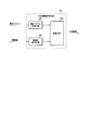
図7は、本実施形態に係る動画像再生装置の構成を示すブロック図であり、同図において、動画像再生装置60は、データ同期部601、信頼度判定部602、補間フレーム生成部603から構成される。尚、撮像装置30より出力された動画像データ、動きベクトル、信頼度に対しては、符号化が行われているが、これらの復号処理については第二の実施形態にて説明する。
次に、本実施形態に係る動画像再生装置の構成について説明する。
図7は、本実施形態に係る動画像再生装置の構成を示すブロック図であり、同図において、動画像再生装置60は、データ同期部601、信頼度判定部602、補間フレーム生成部603から構成される。尚、撮像装置30より出力された動画像データ、動きベクトル、信頼度に対しては、符号化が行われているが、これらの復号処理については第二の実施形態にて説明する。
データ同期部601は、入力された動画像データと、それに対応する動きベクトルと、信頼度との同期をとって、動画像データとそれに対応する動きベクトルを補間フレーム生成部603に出力するとともに、信頼度を信頼度判定部602に出力する。
信頼度判定部602は、入力された信頼度の大きさを判定し、所定の複数の補間処理方法候補の中から、信頼度に応じた適切な補間処理方法を選択するための補間処理フラグを生成して、補間フレーム生成部603に出力する。
補間処理フラグの値は、本実施形態においては、信頼度が高い場合に3、信頼度がやや低い場合に2または1、極端に低い場合に0として設定するが、これに限定されるものではない。
補間処理フラグの値は、本実施形態においては、信頼度が高い場合に3、信頼度がやや低い場合に2または1、極端に低い場合に0として設定するが、これに限定されるものではない。
上記の補間処理フラグは、ブロック毎もしくはフレーム毎で切り替えてもよい。ブロック毎に補間処理フラグが異なる場合は、ブロック単位で補間処理フラグを生成する。また、フレーム毎に補間処理方法が異なる場合は、フレーム単位で補間処理フラグを生成する。
次に、信頼度判定部602の動作について、図8のフローチャートを用いて説明する。
尚、下記に示した閾値は、TH1<TH2<TH3の関係であり、これらの閾値は予め実験等で設定しておく。
尚、下記に示した閾値は、TH1<TH2<TH3の関係であり、これらの閾値は予め実験等で設定しておく。
(ステップS41)基準フレーム上の左上のブロックから順に対象ブロックとし、対象ブロックに対応する信頼度を抽出し、この信頼度と閾値TH1との比較を行い、閾値TH1以下であれば、ステップS42に進み、そうでなければステップS43に進む。
(ステップS42)この信頼度が極端に低いと判断され、補間処理フラグ0が割り当てられステップS48に進む。
(ステップS42)この信頼度が極端に低いと判断され、補間処理フラグ0が割り当てられステップS48に進む。
(ステップS43)対象ブロックの信頼度と閾値TH2との比較を行い、閾値TH2以下であれば、ステップS44に進み、そうでなければステップS45に進む。
(ステップS44)この信頼度がやや低いと判断され、補間処理フラグ1が割り当てられステップS48に進む。
(ステップS44)この信頼度がやや低いと判断され、補間処理フラグ1が割り当てられステップS48に進む。
(ステップS45)対象ブロックの信頼度と閾値TH3との比較を行い、閾値TH3以下であれば、ステップS46に進み、そうでなければステップS47に進む。
(ステップS46)この信頼度が普通と判断され、補間処理フラグ2が割り当てられステップS48に進む。
(ステップS46)この信頼度が普通と判断され、補間処理フラグ2が割り当てられステップS48に進む。
(ステップS47)対象ブロックの信頼度が高いと判定され、補間処理フラグ3が割り当てられ、ステップS48に進む。
(ステップS48)割り当てられた補間処理フラグを対象ブロックと対応付けて図示しない補間処理フラグ格納部へ格納し、ステップS49へ進む。
(ステップS49)対象ブロックが最後のブロックであれば、ステップS41へ戻り、そうでなければ、処理を終了する。
(ステップS49)対象ブロックが最後のブロックであれば、ステップS41へ戻り、そうでなければ、処理を終了する。
補間フレーム生成部603は、入力した動画像データ、動きベクトルおよび補間処理フラグから補間フレームを生成して出力する。
補間フレームの生成方法は、信頼度判定部602から入力した補間処理フラグの値に応じて変更する。例えば、以下のいずれかの方法で補間フレームを生成する。
補間フレームの生成方法は、信頼度判定部602から入力した補間処理フラグの値に応じて変更する。例えば、以下のいずれかの方法で補間フレームを生成する。
(1)補間処理フラグが3の場合:
この補間処理フラグに対応したブロックの信頼度が高い場合は、対象ブロックの動きベクトルに対応する参照ブロックを参照フレームから抽出して補間処理する。この補間処理は、動きベクトルを使った通常の処理である。
この補間処理フラグに対応したブロックの信頼度が高い場合は、対象ブロックの動きベクトルに対応する参照ブロックを参照フレームから抽出して補間処理する。この補間処理は、動きベクトルを使った通常の処理である。
(2)補間処理フラグが1、2の場合:
この補間処理フラグに対応したブロックの信頼度がやや低い場合は、上記(1)の補間処理において、参照ブロックを上下左右に、数画素分拡張して貼り付けて上記(1)と同様な補間処理する。拡張する大きさは、対象ブロックのサイズの1/4程度が好ましい。
この補間処理フラグに対応したブロックの信頼度がやや低い場合は、上記(1)の補間処理において、参照ブロックを上下左右に、数画素分拡張して貼り付けて上記(1)と同様な補間処理する。拡張する大きさは、対象ブロックのサイズの1/4程度が好ましい。
例えば、対象ブロックのサイズが8×8画素の場合、上下左右2画素拡張して、12×12画素で補間することになる。この補間方法により、補間フレームがブロックでカバーされないアンカバード領域が減少するため、補間フレームの劣化を抑えることが可能である。また、補間フレーム上でブロックが重複するオーバーラップ領域に対しては、重複した画素値の平均値を用いる。
(3)補間処理フラグが0の場合:
この補間処理フラグに対応したブロックの信頼度が極端に低い場合は、対象ブロックの動きベクトルを、隣接する周辺ブロックの動きベクトルを用いて補正して補間する。例えば、対象ブロックの周囲3×3の計9ブロック(あるいは、5×5の計25ブロック)分の動きベクトルの中央値、平均値あるいは加重平均をとって、対象ブロックの動きベクトルとする。
この補間方法は、周囲の動きベクトルと比較して、大きく異なる動きベクトルの除去に対して効果がある。
この補間処理フラグに対応したブロックの信頼度が極端に低い場合は、対象ブロックの動きベクトルを、隣接する周辺ブロックの動きベクトルを用いて補正して補間する。例えば、対象ブロックの周囲3×3の計9ブロック(あるいは、5×5の計25ブロック)分の動きベクトルの中央値、平均値あるいは加重平均をとって、対象ブロックの動きベクトルとする。
この補間方法は、周囲の動きベクトルと比較して、大きく異なる動きベクトルの除去に対して効果がある。
これらの補間方法は、上記の方法に限定されるものではなく、取り扱う動画像の種類によって他の方法を用いてもよい。
(動画像再生装置60の動作)
次に、動画像再生装置60の動作について説明する。
データ同期部601は、入力された動画像データ、動きベクトル、信頼度を図示しないバッファに蓄積しておき、所定のタイミングで、信頼度を信頼度判定部602に出力し、補間処理フラグが補間フレーム生成部603に出力されるタイミングで参照フレームおよび対応する動きベクトルを補間フレーム生成部603に出力する。
次に、動画像再生装置60の動作について説明する。
データ同期部601は、入力された動画像データ、動きベクトル、信頼度を図示しないバッファに蓄積しておき、所定のタイミングで、信頼度を信頼度判定部602に出力し、補間処理フラグが補間フレーム生成部603に出力されるタイミングで参照フレームおよび対応する動きベクトルを補間フレーム生成部603に出力する。
補間フレーム生成部603では、動画像データ、動きベクトル、補間処理フラグから各種補間処理フラグに応じた処理により補間フレームを生成して出力動画像として出力する。
信頼度がやや低い場合は、比較的正確な動きベクトルが検出されている可能性があるが、補間フレームでは動きベクトルの正確さの不足によるブロック歪み等の劣化が起こりやすいため、上記(2)の処理のようにデブロッキングフィルタの効果を持った補間処理が望ましい。
一方、信頼度が極端に低い場合、実際の動きとは全く異なる動きベクトルが検出されている可能性があり、補間フレームでは劣化が発生しやすいため、上記(3)の処理のように、動きベクトルの空間的相関が大きいことを仮定して動きベクトルそのものを補正する手法が望ましい。
信頼度がやや低い場合は、比較的正確な動きベクトルが検出されている可能性があるが、補間フレームでは動きベクトルの正確さの不足によるブロック歪み等の劣化が起こりやすいため、上記(2)の処理のようにデブロッキングフィルタの効果を持った補間処理が望ましい。
一方、信頼度が極端に低い場合、実際の動きとは全く異なる動きベクトルが検出されている可能性があり、補間フレームでは劣化が発生しやすいため、上記(3)の処理のように、動きベクトルの空間的相関が大きいことを仮定して動きベクトルそのものを補正する手法が望ましい。
以上のように、実施形態を構成することにより、動きベクトルの確からしさを定量化した値である信頼度に応じた適切な補間処理を行うことにより、複雑な動きを伴う動画像についても、補間フレームの破綻を抑制することができ、再生された動画像の画質が良好となる。
さらに、複雑な動きを伴う動画像を符号化するときにも、動きベクトルの代わりに動画像を含めないので符号量を抑制することができる。
さらに、複雑な動きを伴う動画像を符号化するときにも、動きベクトルの代わりに動画像を含めないので符号量を抑制することができる。
<第二の実施形態>
本発明の第二の実施形態は、第一の実施形態の撮像装置30にデータの符号化部分を追加し、動画像再生装置60にデータの復号化部分を追加したものである。
本発明の第二の実施形態は、第一の実施形態の撮像装置30にデータの符号化部分を追加し、動画像再生装置60にデータの復号化部分を追加したものである。
(撮像装置の構成)
図9は、本実施形態に係る撮像装置の構成を示すブロック図であり、撮像装置30は、撮像素子301、フレームメモリ302、動き検出部303、信頼度生成部304、エンコーダ40、付加情報符号化部50から構成されている。
このうち、撮像素子301、フレームメモリ302、動き検出部303、信頼度生成部304は、第一の実施形態と同じであり説明を省略する。
以下、エンコーダ40および付加情報符号化部50について説明するが、これらは、撮像装置30に設けるのではなく付加機能として設けてもよい。
図9は、本実施形態に係る撮像装置の構成を示すブロック図であり、撮像装置30は、撮像素子301、フレームメモリ302、動き検出部303、信頼度生成部304、エンコーダ40、付加情報符号化部50から構成されている。
このうち、撮像素子301、フレームメモリ302、動き検出部303、信頼度生成部304は、第一の実施形態と同じであり説明を省略する。
以下、エンコーダ40および付加情報符号化部50について説明するが、これらは、撮像装置30に設けるのではなく付加機能として設けてもよい。
エンコーダ40は、公知の技術によって構成され、撮像素子301が出力する動画像データを符号化し、動画像符号化データを出力する。尚、符号化の際、動き検出部303から出力される動きベクトル、信頼度生成部304から出力される信頼度を用いることで、符号化効率の向上、処理量の低減を実現するようなエンコーダへの援用が可能である。
以下、動きベクトル、信頼度のエンコーダへの援用例を挙げる。
(1)エンコーダ内部の動き探索の処理量を大幅に削減することができる。即ち、信頼度が低い場合は、動きベクトルの誤推定を招く可能性があるため、探索範囲を狭くすることで誤推定を抑制できる。
また、対象ブロックの信頼度が、その周囲のブロックの信頼度に対して相対的に大きいか小さいかによって、探索範囲を変更することができる。さらに、予測ベクトルの候補を複数設定し、各予測ベクトルを探索の中心点として探索を行う手法において、所定の閾値以下の指標を与える動きベクトルが得られた場合に、その閾値を信頼度に応じて変更し、探索を打ち切ることで、不必要な探索を抑えることができる。
(1)エンコーダ内部の動き探索の処理量を大幅に削減することができる。即ち、信頼度が低い場合は、動きベクトルの誤推定を招く可能性があるため、探索範囲を狭くすることで誤推定を抑制できる。
また、対象ブロックの信頼度が、その周囲のブロックの信頼度に対して相対的に大きいか小さいかによって、探索範囲を変更することができる。さらに、予測ベクトルの候補を複数設定し、各予測ベクトルを探索の中心点として探索を行う手法において、所定の閾値以下の指標を与える動きベクトルが得られた場合に、その閾値を信頼度に応じて変更し、探索を打ち切ることで、不必要な探索を抑えることができる。
(2)ブロックサイズを切り替えて動き補償が可能なエンコーダにおいては、適切なブロックサイズの選択を少ない処理量で行うことができる。即ち、信頼度の高いブロックについては大きなブロックを、信頼度の低いブロックについては小さなブロックを選択することにより、小さい処理量で高符号化効率を達成することができる。
(3)画面間予測と画面内予測の切り替えを少ない処理量で行うことができる。即ち、信頼度の高い領域では画面間予測の精度が高く、画面内予測が選択される可能性が低いため、信頼度の低い部分のみ画面内予測を行い、画面間予測の結果と比較することで少ない処理量で切り替えを行うことができる。
付加情報符号化部50は、動き検出部303から出力される動きベクトル、信頼度生成部304から出力される信頼度を入力とし、動きベクトルと信頼度それぞれに対して符号化および多重化して、付加情報を生成して出力する。
次に、付加情報符号化部50について詳述する。
図10は、付加情報符号化部50の詳細な構成を示すブロック図であり、同図において、付加情報符号化部50は、動きベクトル符号化部501、信頼度符号化部502、多重化部503から構成される。
図10は、付加情報符号化部50の詳細な構成を示すブロック図であり、同図において、付加情報符号化部50は、動きベクトル符号化部501、信頼度符号化部502、多重化部503から構成される。
動きベクトル符号化部501は、入力された動きベクトルを符号化し、動きベクトル符号化データを多重化部503に出力する。
動きベクトルの符号化方法としては、入力された動きベクトルと、その予測ベクトルとの差分値に対して可変長符号化を行う等の動画像符号化に一般的に用いられている方式を適用する。
動きベクトルの符号化方法としては、入力された動きベクトルと、その予測ベクトルとの差分値に対して可変長符号化を行う等の動画像符号化に一般的に用いられている方式を適用する。
例えば、対象ブロックの動きベクトルと、その予測ベクトルとの差分値に対して可変長符号化を適用し、動きベクトル符号化データを出力する。予測ベクトルは、例えば、動きベクトルの空間的相関を用いた、対象ブロックの近傍ブロック(左、上、右上ブロック)の中央値などが好ましい。
信頼度符号化部502は、入力された信頼度を符号化し、信頼度符号化データを多重化部503に出力する。符号化方法としては、入力された信頼度と、その予測信頼度との差分値に対して可変長符号化等の方法がある。予測値としては、例えば、対象ブロックの近傍ブロックの中央値などが好ましい。
多重化部503は、動きベクトル符号化部501が出力した動きベクトル符号化データと、信頼度符号化部502が出力した信頼度符号化データを入力とし、これらを多重化し、付加情報として出力する。多重化の方法としては、ブロック単位もしくは複数ブロック単位で動きベクトル符号化データと信頼度符号化データをインターリーブして出力してもよいし、1フレーム分の動きベクトル符号化データと信頼度符号化データを順に出力してもよい。
以上、説明したとおり、本実施形態の撮像装置30を用いることで、入力動画像から動画像符号化データと付加情報を生成し、伝送路、記録媒体等へ出力できる。
(動画像再生装置の構成)
図11は、本実施形態に係る動画像再生装置の構成を示すブロック図であり、同図において、動画像再生装置60は、デコーダ70、付加情報復号部80、データ同期部601、信頼度判定部602、補間フレーム生成部603から構成される。
このうち、データ同期部601、信頼度判定部602、補間フレーム生成部603は、第一の実施形態と同じであり説明を省略する。
以下、デコーダ70および付加情報復号部80について説明するが、これらは、動画像再生装置60に設けるのではなく付加機能として設けてもよい。
図11は、本実施形態に係る動画像再生装置の構成を示すブロック図であり、同図において、動画像再生装置60は、デコーダ70、付加情報復号部80、データ同期部601、信頼度判定部602、補間フレーム生成部603から構成される。
このうち、データ同期部601、信頼度判定部602、補間フレーム生成部603は、第一の実施形態と同じであり説明を省略する。
以下、デコーダ70および付加情報復号部80について説明するが、これらは、動画像再生装置60に設けるのではなく付加機能として設けてもよい。
デコーダ70は、公知の技術により、伝送路より受信した動画像符号化データを復号し、動画像復号データをデータ同期部601に出力する。
付加情報復号部80は、伝送路より受信した付加情報を分離、復号し、動きベクトルと信頼度をデータ同期部601に出力する。
この付加情報復号部80は、図12に示すように、逆多重化部801、動きベクトル復号部802、信頼度復号部803から構成されている。
この付加情報復号部80は、図12に示すように、逆多重化部801、動きベクトル復号部802、信頼度復号部803から構成されている。
逆多重化部801は、伝送路より受信した付加情報を逆多重化し、符号化動きベクトルデータと信頼度符号化データに分離して、動きベクトル符号化データを動きベクトル復号部802に出力し、信頼度符号化データを信頼度復号部80に出力する。
動きベクトル復号部802は、符号化動きベクトルデータを入力とし、復号処理を行い、動きベクトルを出力する。動きベクトル符号化データの復号方法としては、動きベクトル符号化部501で使用した符号化方法に対応する公知の復号方法により復号を行う。
信頼度復号部803は、信頼度符号化データを入力とし、復号処理を行い、信頼度を出力する。信頼度符号化データの復号方法としては、信頼度符号化部502で使用した符号化方法に対応する公知の復号方法により復号を行う。
以上、説明した通り、本実施形態の動画像再生装置60を用いることで、伝送路から入力された動画像符号化データと付加情報から動画像を再生することができる。
<第三の実施形態>
本発明の第三の実施形態は、第二の実施形態の撮像装置30にフレーム切替部を追加し、動画像再生装置60については第二の実施形態と同じものである。
以下、相違点についてのみ説明する。
本発明の第三の実施形態は、第二の実施形態の撮像装置30にフレーム切替部を追加し、動画像再生装置60については第二の実施形態と同じものである。
以下、相違点についてのみ説明する。
(撮像装置の構造)
図13は、本実施形態に係る撮像装置の構成を示すブロック図であり、同図において、撮像装置30は、撮像素子301、フレーム切替部90、フレームメモリ302、動き検出部303、信頼度生成部304、エンコーダ40、付加情報符号化部50から構成されている。
このうち、撮像素子301、フレームメモリ302、動き検出部303、信頼度生成部304、エンコーダ40、付加情報符号化部50は、第二の実施形態と同じであり説明を省略する。また、エンコーダ40および付加情報符号化部50は、撮像装置30に設けるのではなく付加機能として設けてもよい。
以下、追加されたフレーム切替部90と、これにより変更された点について説明する。
図13は、本実施形態に係る撮像装置の構成を示すブロック図であり、同図において、撮像装置30は、撮像素子301、フレーム切替部90、フレームメモリ302、動き検出部303、信頼度生成部304、エンコーダ40、付加情報符号化部50から構成されている。
このうち、撮像素子301、フレームメモリ302、動き検出部303、信頼度生成部304、エンコーダ40、付加情報符号化部50は、第二の実施形態と同じであり説明を省略する。また、エンコーダ40および付加情報符号化部50は、撮像装置30に設けるのではなく付加機能として設けてもよい。
以下、追加されたフレーム切替部90と、これにより変更された点について説明する。
フレーム切替部90は、入力された入力動画像を、基準フレームと参照フレームに分類してそれぞれ出力する。入力動画像のフレームレートと基準フレームのフレームレートを切り替えて、基準フレームと参照フレームに分類する。尚、入力動画像のフレームレートと基準フレームのフレームレートの比率は1/2,1/3,1/4等のいずれでも良い。
本実施形態では、比率を1/2とし、順次入力される入力動画像を1枚おきに基準フレームと参照フレームに切り替えて出力するものとする。
本実施形態では、比率を1/2とし、順次入力される入力動画像を1枚おきに基準フレームと参照フレームに切り替えて出力するものとする。
フレームメモリ302は、フレーム切替部90が出力する参照フレームを蓄積する。蓄積された参照フレームは、動き検出部303で利用されるとともに、エンコーダ40に適切なタイミングで出力され、動画像データとして符号化される。
(撮像装置30の動作)
次に、本実施形態に係る撮像装置30の動作について説明する。
説明の簡単のため、入力動画像のフレームレートを60fps、基準フレーム、参照フレームのフレームレートを30fpsとする。
次に、本実施形態に係る撮像装置30の動作について説明する。
説明の簡単のため、入力動画像のフレームレートを60fps、基準フレーム、参照フレームのフレームレートを30fpsとする。
まず、撮像素子301により撮影された60fpsの入力動画像は、フレーム切替部90において30fpsの基準フレームと参照フレームに分類され、30fpsの参照フレームはフレームメモリ302で蓄積され、30fpsの基準フレームは動き検出部303および信頼度生成部304に入力される。
次に、動き検出部303では、基準フレームに対応する参照フレームをフレームメモリ302から呼び出し、それらを用いて動きベクトルを導出する。
信頼度生成部304は、動き検出部303が出力した動きベクトルおよび予測誤差から信頼度を生成して出力する。
信頼度生成部304は、動き検出部303が出力した動きベクトルおよび予測誤差から信頼度を生成して出力する。
エンコーダ40は、動きベクトルと信頼度を用いて、参照フレームを符号化して動画像符号化データを出力する。また、付加情報符号化部50は、動きベクトルと信頼度をそれぞれ符号化して多重化した付加情報を出力する。
これらの動画像符号化データと付加情報を伝送路に出力し、表示側では第二の実施形態の動画像再生装置60を用いることで、動画像符号化データと付加情報から動画像を再生できる。
これらの動画像符号化データと付加情報を伝送路に出力し、表示側では第二の実施形態の動画像再生装置60を用いることで、動画像符号化データと付加情報から動画像を再生できる。
次に、本実施形態に係る動画像再生装置60における補間フレームの生成について説明する。
図14は、本実施形態における動画像の入力からフレーム補間までの処理の概略を説明するための図であり、横軸は時間方向を示したものである。尚、図14(A)は、撮像装置30における動きベクトルの検出の処理、図14(B)は、動画像再生装置60におけるフレーム補間処理に相当する。
図14は、本実施形態における動画像の入力からフレーム補間までの処理の概略を説明するための図であり、横軸は時間方向を示したものである。尚、図14(A)は、撮像装置30における動きベクトルの検出の処理、図14(B)は、動画像再生装置60におけるフレーム補間処理に相当する。
撮像装置30では、撮影した60fpsの動画像を入力とする。入力された動画像は、フレーム切替部90によって1枚おきに基準フレームと参照フレームに分類され、参照フレームが符号化されて動画像符号化データとして出力されるとともに、基準フレームと参照フレームの間の動きに相当する動きベクトルが生成されて信頼度と合わせて付加情報として出力される。
動画像再生装置60では、動画像符号化データから復号して得られる動画像復号データの各フレームを用い、動きベクトルと信頼度を用いて補間フレームを生成することで、60fpsの動画像を再生する。
以上、説明した通り、本実施形態の撮像装置を用いることで、入力動画像から動画像符号化データと付加情報を出力できるので、フレームレートの高い動画像を入力とした場合、より正確な動きベクトルを検出することが可能である。
さらに、本実施形態の動画像再生装置を用いることで、撮像装置で判定した信頼度に基づき、各ブロックに対して適切な補間処理を施せるので画質が良好である。
さらに、本実施形態の動画像再生装置を用いることで、撮像装置で判定した信頼度に基づき、各ブロックに対して適切な補間処理を施せるので画質が良好である。
<その他の実施形態>
また、本発明は上述した実施形態に限定されず、本発明の要旨を逸脱しない範囲内で各種の変形、修正が可能であるのは勿論である。
例えば、動画像データ処理装置を上述のフレームメモリ302、動き検出部303、信頼度生成部304から構成してもよい。また、符号化装置を上記の動画像データ処理装置、エンコーダ40、付加情報符号化部50から構成してもよい。
また、本発明は上述した実施形態に限定されず、本発明の要旨を逸脱しない範囲内で各種の変形、修正が可能であるのは勿論である。
例えば、動画像データ処理装置を上述のフレームメモリ302、動き検出部303、信頼度生成部304から構成してもよい。また、符号化装置を上記の動画像データ処理装置、エンコーダ40、付加情報符号化部50から構成してもよい。
この場合、第一の実施形態の撮像装置は、撮像素子301に上記の動画像データ処理装置を組み合わせて構成できる。また、第二の実施形態の撮像装置は、撮像素子301に上記の符号化装置を組み合わせて構成できる。
また、フレームレート変換装置をデータ同期部601、信頼度判定部602、補間フレーム生成部603から構成してもよい。また、復号装置をデコーダ70、付加情報復号部80、上記のフレームレート変換装置から構成してもよい。
この場合、第一の実施形態の動画像再生装置は、上記のフレームレート変換装置に動画像や動きベクトルや信頼度を読み取る装置と再生された動画像を表示する表示装置を組み合わせて構成できる。また、第二の実施形態の動画像再生装置は、符号化された動画像と符号化された付加情報を読み取る装置と、上記の符号化装置、再生された動画像を表示する表示装置を組み合わせて構成できる。
尚、第一および第二の実施形態の撮像装置においては、信頼度は生成せずに従来と同様な動画像と動きベクトルを出力する。そして、第一および第二の実施形態の動画像再生装置において、補間フレームを作成する前に信頼度を生成してから補間処理フラグを作成するようにしてもよい。また、算出した信頼度から直接補間処理フラグを生成するようにしてもよい。
また、動画像データ処理装置を上述のフレーム切替部90、フレームメモリ302、動き検出部303、信頼度生成部304から構成し、符号化装置をこの動画像データ処理装置にエンコーダ40、付加情報符号化部50を組み合わせた構成としてもよい。
この場合、第三の実施形態の撮像装置は、撮像素子301にこの動画像データ処理装置を組み合わせるか、また、撮像素子301にこの符号化装置を組み合わせて構成できる。
また、第三の実施形態の動画像再生装置は、上述の第一または第二の実施形態の動画像再生装置と同じに構成できる。
また、第三の実施形態の動画像再生装置は、上述の第一または第二の実施形態の動画像再生装置と同じに構成できる。
30…撮像装置、301…撮像素子、302…フレームメモリ、303…動き検出部、304…信頼度生成部、3031…対象ブロック抽出部、3032…参照領域抽出部、3033…残差算出部、3034…動きベクトル決定部、3034…動きベクトル決定部、40…エンコーダ、50…付加情報符号化部、501…動きベクトル符号化部、502…信頼度符号化部、503…多重化部、60…動画像再生装置、601…データ同期部、602…信頼度判定部、603…補間フレーム生成部、70…デコーダ、80…付加情報復号部、801…逆多重化部、802…動きベクトル復号部、803…信頼度復号部、90…フレーム切替部。
Claims (9)
- 動画像データのフレームデータを複数のブロックに分割し、前記動画像データの基準フレームデータと参照フレームデータとから、前記各ブロックに対する動きベクトルと予測誤差を検出する動き検出部と、前記各ブロックの予測誤差に対する動きベクトルの確からしさを示す信頼度を生成する信頼度生成部と、を備え、
前記動画像データの基準フレームデータ、並びに、前記動きベクトルおよび信頼度を出力することを特徴とする動画像データ処理装置。 - 前記信頼度生成部は、前記予測誤差を量子化した値により信頼度を生成することを特徴とする請求項1に記載の動画像データ処理装置。
- 前記信頼度生成部は、前記動き検出部で検出した動きベクトルにより関連付けられる参照ブロックと対象ブロックから得られる、前記動き検出に使った成分とは異なる色成分における予測誤差を量子化した値を少なくとも用いて信頼度を生成することを特徴とする請求項1に記載の動画像データ処理装置。
- 前記信頼度生成部は、各ブロックの複雑さを示すアクティビティと前記予測誤差との比により信頼度を生成することを特徴とする請求項1に記載の動画像データ処理装置。
- 動画像データを、フレーム毎に基準フレームと参照フレームに切り替えて出力するフレーム切替部を備え、前記動き検出部は、前記フレーム切替部から出力される基準フレームデータと参照フレームデータから動きベクトルと予測誤差を生成し、前記信頼度生成部は、前記動き検出部で生成した動きベクトルと予測誤差に基づいて、前記信頼度を生成することを特徴とする請求項1乃至4のいずれかに記載の動画像データ処理装置。
- 前記信頼度生成部で生成されたブロックごとの信頼度の値に基づいて、適切な補間処理方法を選択するための補間処理フラグを算出し、生成する信頼度判定部と、
前記動画像データと前記動きベクトルと前記補間処理フラグを用いて、適切な補間処理方法を選択して前記動画像データのフレーム間に補間フレームを生成する補間フレーム生成部と、を備えることを特徴とする請求項1乃至5のいずれかに記載の動画像データ処理装置。 - 前記補間フレーム生成部は、ブロック毎の前記補間処理フラグが前記第一の値を示す場合には通常のフレーム補間処理を適用し、前記補間フラグが前記第二の値を示す場合には補間時に画質劣化が発生する領域の画素値を修正する補間処理を適用し、前記補間フラグが前記第三の値を示す場合には、動きベクトルの値を修正する補間処理を適用することを特徴とする請求項6に記載の動画像データ処理装置。
- 撮影した動画像データを出力する撮像素子と、前記撮像素子が出力する動画像データを符号化した動画像符号化データを出力するエンコーダと、請求項1乃至5のいずれかに記載の動画像データ処理装置と、前記動画像データ処理装置で生成された動きベクトルおよび信頼度をそれぞれ符号化して多重化した付加情報を出力する付加情報符号化部と、を備えることを特徴とする撮像装置。
- 請求項6または7に記載の動画像データ処理装置を有し、入力された動画像符号化データを復号するデコーダと、入力された付加情報を逆多重化して復号し、動きベクトルおよび信頼度を出力する付加情報復号部と、を備え、前記信頼度判定部は、前記付加情報復号部で復号された信頼度から前記補間処理フラグを生成し、前記補間フレーム生成部は、前記前記デコーダで復号された動画像データと、前記付加情報復号部で復号された動きベクトルと、前記信頼度判定部で生成された補間処理フラグに基づいて、適切な補間処理方法を選択して補間フレームを生成することを特徴とする動画像再生装置。
Applications Claiming Priority (2)
| Application Number | Priority Date | Filing Date | Title |
|---|---|---|---|
| JP2009-139287 | 2009-06-10 | ||
| JP2009139287A JP2010288006A (ja) | 2009-06-10 | 2009-06-10 | 動画像データ処理装置、撮像装置および動画像再生装置 |
Publications (1)
| Publication Number | Publication Date |
|---|---|
| WO2010143497A1 true WO2010143497A1 (ja) | 2010-12-16 |
Family
ID=43308756
Family Applications (1)
| Application Number | Title | Priority Date | Filing Date |
|---|---|---|---|
| PCT/JP2010/058186 Ceased WO2010143497A1 (ja) | 2009-06-10 | 2010-05-14 | 動画像データ処理装置、撮像装置および動画像再生装置 |
Country Status (2)
| Country | Link |
|---|---|
| JP (1) | JP2010288006A (ja) |
| WO (1) | WO2010143497A1 (ja) |
Cited By (1)
| Publication number | Priority date | Publication date | Assignee | Title |
|---|---|---|---|---|
| JP2016218425A (ja) * | 2015-05-20 | 2016-12-22 | パナソニックIpマネジメント株式会社 | 画像表示装置及び画像処理装置 |
Families Citing this family (1)
| Publication number | Priority date | Publication date | Assignee | Title |
|---|---|---|---|---|
| JP6723173B2 (ja) * | 2017-02-10 | 2020-07-15 | 富士フイルム株式会社 | 画像処理装置、方法およびプログラム |
Citations (6)
| Publication number | Priority date | Publication date | Assignee | Title |
|---|---|---|---|---|
| JPH07203442A (ja) * | 1993-12-27 | 1995-08-04 | Victor Co Of Japan Ltd | デジタル伝送装置 |
| JPH1023374A (ja) * | 1996-07-09 | 1998-01-23 | Oki Electric Ind Co Ltd | 画像信号の方式変換装置およびフィールド数変換方法 |
| JPH11252567A (ja) * | 1998-03-02 | 1999-09-17 | Toshiba Corp | 画像信号の符号化装置及びその方法と画像信号の復号化装置及びその方法 |
| JP2003224854A (ja) * | 2002-01-29 | 2003-08-08 | Hitachi Ltd | 動きベクトル検出装置及び画像処理装置並びにコンピュータ・ソフトウエア |
| JP2004274628A (ja) * | 2003-03-11 | 2004-09-30 | Sony Corp | 動き検出装置、動き検出方法及びプログラム |
| JP2008099281A (ja) * | 2006-10-12 | 2008-04-24 | Thomson Licensing | 動き補償画像の補間方法、及びその方法を実現する装置 |
-
2009
- 2009-06-10 JP JP2009139287A patent/JP2010288006A/ja active Pending
-
2010
- 2010-05-14 WO PCT/JP2010/058186 patent/WO2010143497A1/ja not_active Ceased
Patent Citations (6)
| Publication number | Priority date | Publication date | Assignee | Title |
|---|---|---|---|---|
| JPH07203442A (ja) * | 1993-12-27 | 1995-08-04 | Victor Co Of Japan Ltd | デジタル伝送装置 |
| JPH1023374A (ja) * | 1996-07-09 | 1998-01-23 | Oki Electric Ind Co Ltd | 画像信号の方式変換装置およびフィールド数変換方法 |
| JPH11252567A (ja) * | 1998-03-02 | 1999-09-17 | Toshiba Corp | 画像信号の符号化装置及びその方法と画像信号の復号化装置及びその方法 |
| JP2003224854A (ja) * | 2002-01-29 | 2003-08-08 | Hitachi Ltd | 動きベクトル検出装置及び画像処理装置並びにコンピュータ・ソフトウエア |
| JP2004274628A (ja) * | 2003-03-11 | 2004-09-30 | Sony Corp | 動き検出装置、動き検出方法及びプログラム |
| JP2008099281A (ja) * | 2006-10-12 | 2008-04-24 | Thomson Licensing | 動き補償画像の補間方法、及びその方法を実現する装置 |
Cited By (1)
| Publication number | Priority date | Publication date | Assignee | Title |
|---|---|---|---|---|
| JP2016218425A (ja) * | 2015-05-20 | 2016-12-22 | パナソニックIpマネジメント株式会社 | 画像表示装置及び画像処理装置 |
Also Published As
| Publication number | Publication date |
|---|---|
| JP2010288006A (ja) | 2010-12-24 |
Similar Documents
| Publication | Publication Date | Title |
|---|---|---|
| US8903222B2 (en) | Image reproducing apparatus, image reproducing method, image capturing apparatus, and control method therefor | |
| JP4145275B2 (ja) | 動きベクトル検出・補償装置 | |
| US8233746B2 (en) | Image processing device, image processing method and program | |
| US8102436B2 (en) | Image-capturing apparatus and method, recording apparatus and method, and reproducing apparatus and method | |
| KR20100021574A (ko) | 화상처리장치, 화상처리방법 및 프로그램 | |
| JPWO2011078002A1 (ja) | 画像処理装置および方法、並びにプログラム | |
| KR101049922B1 (ko) | 화상 처리 장치, 화상 처리 방법 및 프로그램 | |
| JP4119092B2 (ja) | 画像信号のフレーム数変換方法および装置 | |
| WO2012098845A1 (ja) | 画像符号化方法、画像符号化装置、画像復号方法及び画像復号装置 | |
| JP5216984B2 (ja) | 動き情報取得装置及び画像処理装置 | |
| JP2013150164A (ja) | 符号化装置および符号化方法、並びに、復号装置および復号方法 | |
| JP5130245B2 (ja) | 撮影解像度予測型動画像符号化装置および復号装置 | |
| WO2010143497A1 (ja) | 動画像データ処理装置、撮像装置および動画像再生装置 | |
| JP2007122232A (ja) | 画像処理装置及びプログラム | |
| WO2012056924A1 (ja) | 画像処理装置と画像処理方法 | |
| JP2019022225A (ja) | 画像圧縮装置およびプログラム | |
| JP2019083433A (ja) | 映像送信装置、映像受信装置及びプログラム | |
| JP2002010267A (ja) | 動きベクトル変換装置及び方法 | |
| JP4779207B2 (ja) | 動きベクトル変換装置及び動きベクトル変換方法 | |
| JP5750191B2 (ja) | 画像復号化方法 | |
| JP2014131136A (ja) | 動画像圧縮装置、動画像復号装置およびプログラム | |
| JP4556286B2 (ja) | 動きベクトル変換装置及び方法 | |
| JP4529295B2 (ja) | 動きベクトル変換方法及び変換装置 | |
| JP2001309389A (ja) | 動きベクトル変換装置及び方法 | |
| JP2014179921A (ja) | 動画像符号化装置及びその制御方法、プログラム |
Legal Events
| Date | Code | Title | Description |
|---|---|---|---|
| 121 | Ep: the epo has been informed by wipo that ep was designated in this application |
Ref document number: 10786028 Country of ref document: EP Kind code of ref document: A1 |
|
| NENP | Non-entry into the national phase |
Ref country code: DE |
|
| 122 | Ep: pct application non-entry in european phase |
Ref document number: 10786028 Country of ref document: EP Kind code of ref document: A1 |