WO2010143375A1 - 顕微鏡装置および制御プログラム - Google Patents
顕微鏡装置および制御プログラム Download PDFInfo
- Publication number
- WO2010143375A1 WO2010143375A1 PCT/JP2010/003681 JP2010003681W WO2010143375A1 WO 2010143375 A1 WO2010143375 A1 WO 2010143375A1 JP 2010003681 W JP2010003681 W JP 2010003681W WO 2010143375 A1 WO2010143375 A1 WO 2010143375A1
- Authority
- WO
- WIPO (PCT)
- Prior art keywords
- unit
- imaging
- axis direction
- optical axis
- objective lens
- Prior art date
- Legal status (The legal status is an assumption and is not a legal conclusion. Google has not performed a legal analysis and makes no representation as to the accuracy of the status listed.)
- Ceased
Links
Images

Classifications
-
- G—PHYSICS
- G02—OPTICS
- G02B—OPTICAL ELEMENTS, SYSTEMS OR APPARATUS
- G02B21/00—Microscopes
- G02B21/36—Microscopes arranged for photographic purposes or projection purposes or digital imaging or video purposes including associated control and data processing arrangements
- G02B21/365—Control or image processing arrangements for digital or video microscopes
Definitions
- the present invention relates to a microscope apparatus and a control program.
- a microscope apparatus that generates a plurality of images having different positions in the optical axis direction (so-called Z direction) of an objective lens is known.
- a stereoscopic image is constructed from a plurality of images (slice images) having different positions in the Z direction, and a development view of an image projected in the horizontal and vertical directions is constructed.
- the present invention has been made in view of the above problems, and an object of the present invention is to suppress variation in brightness in a plurality of generated images when generating a plurality of images having different positions of the objective lens in the optical axis direction. To do.
- the microscope apparatus of the present invention includes an objective lens, a stage on which a test object is placed, an imaging unit that captures an image of the test object, and the objective lens and the stage in the optical axis direction of the objective lens.
- a moving unit that changes the relative position of the light source, a calculation unit that obtains a luminance adjustment parameter for each of at least two surfaces in the test object that have different positions in the optical axis direction, and at least two of the luminance adjustment parameters
- a determination unit that determines a luminance adjustment parameter for performing imaging by the imaging unit on each of the surfaces in the plurality of objects having different positions in the optical axis direction.
- the brightness adjustment parameter may include at least one of illumination intensity when illuminating the test object, a moving speed of the stage, and a time interval of imaging by the imaging unit.
- an illumination unit that irradiates the test object with laser light
- the brightness adjustment parameter includes at least one of the intensity of the laser light and the gain when the laser light is generated from a light source as the illumination intensity. May be included.
- the determination unit performs an interpolation calculation based on at least two of the luminance adjustment parameters, and sets the luminance adjustment parameters for performing imaging by the imaging unit on each of a plurality of surfaces having different positions in the optical axis direction. You may decide.
- the moving unit includes a control unit that moves the stage at a predetermined speed, performs imaging by the imaging unit at predetermined time intervals, and generates a plurality of pre-scan images. Based on the pre-scan image, the surface corresponding to both ends of the test object in the optical axis direction is estimated, and the brightness adjustment parameter is obtained for each of a plurality of surfaces including the surfaces corresponding to the both ends. good.
- control unit may generate a plurality of observation images by performing imaging by the imaging unit while moving the stage by the moving unit based on the luminance parameter determined by the determining unit.
- a three-dimensional image generation unit that generates a three-dimensional image of the test object based on a plurality of the observation images may be provided.
- the confocal microscope system 1 shown in FIG. 1 will be described as an example.
- the confocal microscope system 1 includes a light source unit 10, a confocal microscope 20, and a computer 50 as shown in FIG.
- the light source unit 10 includes a light source that emits illumination light to the confocal microscope 20.
- a light source in addition to the laser, white light such as an ultra-high pressure mercury lamp, a xenon lamp, a metal halide lamp, or the like is used.
- white light is used as the light source, an excitation filter is installed between the light source and a beam shaping optical system described later.
- a laser light source is provided as an example.
- the confocal microscope 20 includes a beam shaping optical system 21, a confocal slit diaphragm 22, an illumination system collimating lens 23, a beam splitter 24, a scanner 25, a scanner lens 26, a second objective lens 27, an objective lens 28, a stage 29, and an image.
- Each unit includes a system collimating lens 30, a condenser lens 31, an imaging unit 32, reflection mirrors 33 and 34, and a filter 35.
- the beam shaping optical system 21 is, for example, a cylindrical microlens
- the beam splitter 24 is, for example, a dichroic mirror.
- the filter 35 is, for example, a barrier filter.
- the scanner 25 includes a scan mirror 25a whose both surfaces are reflection surfaces.
- the scan mirror 25a is rotatable in the direction of arrow A in FIG. 1, and scans the irradiation light in the direction of arrow B by rotating (details will be described later).
- a specimen T such as a biological sample is placed on the stage 29.
- the stage 29 can be moved in a three-dimensional direction (xyz direction in FIG. 1) by a driving unit (not shown).
- the imaging unit 32 includes, for example, an imaging element such as a CCD, a light receiving element, and the like, and generates two-dimensional luminance distribution data (observation image) from imaging light described later.
- the computer 50 includes an operation unit 51 such as a mouse and a keyboard, a display unit 52 including an LCD, etc., and a control unit 53 that detects an operation on the operation unit 51 and displays an image or the like on the display unit 52. Further, the control unit 53 controls the light source unit 10, the scanner 25, and the imaging unit 32, and acquires a two-dimensional observation image from the imaging unit 32 (details will be described later).
- an operation unit 51 such as a mouse and a keyboard
- the control unit 53 controls the light source unit 10, the scanner 25, and the imaging unit 32, and acquires a two-dimensional observation image from the imaging unit 32 (details will be described later).
- the illumination light emitted from the light source unit 10 is formed into a linear light beam that is long in one direction by the beam shaping optical system 21.
- This linear light beam (hereinafter referred to as “light beam S”) is collected at a position optically conjugate with the observation surface Ta of the sample T.
- a confocal slit diaphragm 22 having a plurality of slit-like openings is installed.
- the light beam S formed in a line by the beam shaping optical system 21 enters the opening of the confocal slit diaphragm 22.
- the light beam S is formed into a line-shaped light beam having a predetermined width by the opening.
- the light beam S that has passed through the confocal slit diaphragm 22 is converted into parallel light by the illumination system collimating lens 23 and reflected in the direction of the scanner 25 by the reflection mirror 33. Then, the light beam S reflected by the first surface 25a-s of the scan mirror 25a is reflected in the direction of the scanner lens 26.
- the light beam S that has passed through the scanner lens 26 passes through the second objective lens 27 and the objective lens 28 in order, and is condensed on the observation surface Ta of the sample T as a linear illumination region.
- the sample T When the light beam S is irradiated on the sample T, the sample T emits fluorescence or reflects the light beam S.
- This fluorescent or reflected light (hereinafter referred to as “light beam K”) is guided to the confocal slit diaphragm 22 along a path opposite to that of the light beam S as illumination light. That is, the light beam K is guided to the scanner 25 through the objective lens 28, the second objective lens 27, and the scanner lens 26 in order.
- the light beam K reflected by the first surface 25a-s of the scan mirror 25a is reflected in the direction of the reflection mirror 33, and further reflected by the reflection mirror 33 in the direction of the illumination system collimating lens 23.
- the light beam K collected by the illumination system collimating lens 23 enters the confocal slit stop 22.
- the confocal slit diaphragm 22 functions as a confocal diaphragm of the imaging optical system, and cuts off excess light out of focus.
- the light beam K that has passed through the confocal slit diaphragm 22 is reflected by the beam splitter 24 toward the imaging system collimating lens 30.
- the light beam K converted into parallel light by the imaging system collimator lens 30 is reflected by the reflecting mirror 34 toward the scanner 25.
- the light beam K is reflected by the second surface 25a-r of the scan mirror 25a in the direction of the condensing lens 31, and is imaged on the detection surface of the imaging unit 32 by the condensing lens 31 as a two-dimensional luminance distribution.
- the luminance distribution imaged on the detection surface of the imaging unit 32 corresponds to the luminance distribution on the observation surface Ta.
- the control unit 53 detects this and controls the light source unit 10 to start irradiating the specimen T with illumination light.
- the control unit 53 controls the scanner 25 to rotate the scan mirror 25a.
- the irradiation region of the light beam S on the sample T is moved in the minor axis direction (direction of arrow B).
- the direction of the arrow B corresponds to the scanning direction by the scanner 25, and the scanner 25 scans the sample T by scanning the light beam S.
- the scanner 25 descans the light beam K reflected by the sample T and guides it to the imaging unit 32.
- the user Prior to the instruction to start observation, the user operates the operation unit 51 to move the stage 29 and arrange the portion to be observed in the sample T at the center of the visual field of the objective lens 28. Further, the stage 29 is moved also in the Z direction, and approximate focusing is performed on a portion to be observed. Note that the user can make these adjustments by visually observing an observation image acquired by the imaging unit 32 and displayed on the display unit 52. Further, when the confocal microscope system 1 has a configuration capable of observing the phase difference, the user may perform the above-described adjustment by visually observing the phase difference image.
- step S1 the control unit 53 determines whether an observation start instruction has been performed.
- the control unit 53 waits until it is determined that an observation start instruction has been issued, and proceeds to step S2 if it is determined that an observation start instruction has been issued.
- the observation start instruction is performed by a user operation via the operation unit 51. Further, when the confocal microscope system 1 has a timer or the like, the control unit 53 itself may issue an observation start instruction based on the timer.
- step S2 the control unit 53 controls each unit and performs pre-scanning.
- This pre-scan is a scan intended to detect a Top slice and a Bottom slice in step S3 described later.
- the control unit 53 performs imaging by the imaging unit 29 while moving the stage 29 in the Z direction, and acquires a plurality of pre-scan images.
- the pre-scan is performed under predetermined illumination conditions and imaging conditions.
- the imaging conditions may be lower than when performing actual observation (hereinafter referred to as “main observation”).
- the start point and end point in the Z direction in the pre-scan are, for example, positions that are moved up and down by a predetermined width with reference to the position in the Z direction when the observation start instruction is given.
- the pre-scan interval (the moving speed of the stage 29 and the imaging interval by the imaging unit 32) may be specified in advance by a user operation via the operation unit 51, or may be automatically specified by the control unit 53. good.
- step S3 the control unit 53 detects a Top slice and a Bottom slice based on a plurality of pre-scan images obtained by the pre-scan performed in Step S2.
- the controller 53 first obtains a histogram of the luminance distribution for each of the plurality of pre-scan images obtained in step S2, and determines the presence or absence of an object (for example, a cell). Presence / absence of the object can be determined by comparing a threshold value determined in advance based on the illumination condition and the imaging condition at the time of executing the pre-scan and the luminance value of each pre-scan image.
- the threshold value described above may be specified by a user operation via the operation unit 51.
- the control unit 53 determines, for example, the presence or absence of an object along the Z direction in order from the side closer to the objective lens 28, and sets a pre-scan image that is initially determined to have “the object” as a Top slice. Further, the control unit 53 determines the presence / absence of an object along the Z direction, and sets a pre-scan image that has changed from “the object is present” to “the object is not present” as a Bottom slice.
- the determination of the presence / absence of the object related to the previous pre-scan image may be performed again with the condition regarding the threshold changed narrowly.
- the detected Top slice and Bottom slice are reflected in the movement range in the Z direction during the main observation described later. Therefore, in order to ensure that this moving range includes the portion where the object exists, the Top slice may be positioned closer to the objective lens 28 and the Bottom slice may be positioned farther from the objective lens 28.
- the pre-scan image closer to the objective lens 28 than the pre-scan image initially determined as “the object is present” is the Top slice
- the Bottom slice “the object is present”.
- a pre-scan image farther from the objective lens 28 than the pre-scan image changed to “no object” may be used as a Bottom slice.
- the pre-scan described in step S2 and the detection of the Top slice and Bottom slice described in step S3 may be performed simultaneously. That is, the control unit 53 determines the presence or absence of an object every time a pre-scan image is acquired. By adopting such a configuration, the pre-scan interval is narrowed until the Top slice is detected, and after the Top slice is detected, the pre-scan interval is widened. It is also possible.
- step S4 the control unit 53 selects a reference slice based on the Top slice and the Bottom slice detected in step S3.
- the reference slice is a slice that is a target for adjusting the brightness adjustment parameter in step S5 described later. Which slice is selected as the reference slice based on the Top slice and the Bottom slice may be determined in advance, or may be designated by a user operation via the operation unit 51. Here, a description will be given assuming that, in addition to the Top slice and Bottom slice, a total of four slices corresponding to 1/3 and 2/3 of the Top slice and Bottom slice are selected as reference slices.
- step S5 the control unit 53 adjusts the brightness adjustment parameter with respect to the reference slice selected in step S4.
- the laser intensity of the laser light source in the light source unit 10 will be described as an example of the brightness adjustment parameter.
- the control unit 53 performs imaging by the imaging unit 32 while adjusting the laser intensity for each of the reference slices selected in step S4. Then, an index value is obtained from the image obtained by imaging, and an optimal brightness adjustment parameter is determined by comparing with an threshold value.
- the index value is a luminance histogram, the number of luminance saturation pixels, or the like. For example, if the luminance value is 0 to 4095 and the ratio of pixels with luminance value 4095 (luminance saturation pixel) is 0.05 to 0.06%, the laser intensity at that time is the optimum luminance adjustment. It can be determined that it is a parameter.
- the brightness adjustment parameter is assumed to have been linearly corrected in advance. Further, an image obtained by performing imaging by the imaging unit 32 may be displayed on the display unit 52 while adjusting the laser intensity.
- the optimum brightness adjustment parameter may be obtained again by changing the threshold value to be compared with the index value and relaxing the condition. Further, the user may be notified that the optimum brightness adjustment parameter cannot be obtained using the display unit 52 or the like.
- the brightness adjustment parameter for each reference slice obtained in this way has a different value for each slice.
- the brightness adjustment parameter is laser intensity
- the value of the laser intensity increases as the slice is farther from the objective lens 28.
- step S6 the control unit 53 determines the luminance adjustment parameter for each slice of the main observation based on the adjustment result of the luminance adjustment parameter performed in step S5.
- the control unit 53 obtains a brightness adjustment parameter for each slice of the main observation in step S7 described later.
- the slice to be subjected to the main observation may be determined in advance, or may be designated by a user operation via the operation unit 51.
- slices at the same interval as the pre-scan performed in Step S2 between the Top slice detected in Step S3 and the Bottom slice are targeted for the main observation.
- the control unit 53 performs, for example, the spline interpolation using the brightness adjustment parameter of the reference slice obtained in step S5, and determines the brightness adjustment parameter of each slice.
- An interpolation method other than spline interpolation, such as linear interpolation, may be used. Further, the interpolation method may be determined according to the number of reference slices selected in step S4.
- step S7 the control unit 53 controls each unit and performs the main observation (Z stack observation).
- the control unit 53 performs imaging by the imaging unit 29 while moving the stage 29 in the Z direction, and acquires a plurality of observation images.
- a three-dimensional image may be generated from a plurality of observation images obtained by imaging.
- step S8 the control unit 53 records a plurality of observation images generated by the main observation performed in step S7 in a recording unit (not shown), and ends a series of processes.
- the control unit 53 may record only the three-dimensional image, or may record a plurality of observation images together with the three-dimensional image.
- the brightness adjustment parameter for each slice determined in step S6 may be recorded in association with the image.
- the laser intensity of the laser light source in the light source unit 10 has been described as an example of the brightness adjustment parameter.
- the intensity (luminance) of incident light finally incident on the imaging unit 32 can be adjusted.
- a parameter may be used.
- the scan speed (such as the time for irradiating laser light to one line) may be used as the brightness adjustment parameter, or the gain of the light source unit 10 by voltage adjustment may be used as the brightness adjustment parameter.
- two or more parameters may be used in combination. Each parameter differs in the intensity of illumination light, the time required for observation, the image quality of the image obtained by the imaging unit 32, the influence on the sample T, and the like. Therefore, a configuration in which the brightness adjustment parameter can be selected as appropriate in accordance with the type of specimen T, the purpose of observation, and the like may be adopted. Furthermore, brightness adjustment parameters other than those described above may be used.
- the case where any of the slices at the time of pre-scan is selected as the reference slice is exemplified, but a slice corresponding to the middle of the slice at the time of pre-scan may be selected as the reference slice.
- the case where the interval between the slices at the time of pre-scanning and the interval between the slices at the time of the main observation are illustrated is exemplified, but these do not necessarily have to match. In either case, it can be dealt with by an interpolation calculation or the like.
- the user may be authenticated and proceed to the next step.
- a confirmation step by the user may be provided after detecting the Top slice and Bottom slice in Step S3, after selecting the reference slice in Step S4, and after determining the brightness adjustment parameter in Step S6.
- the reference slice selected in step S4 and the brightness adjustment parameter determined in step S6 may be recorded in a database and used for subsequent observations. For example, when performing observation with different types of specimen T (including Top slice, Bottom slice, etc.) and observation conditions (slice interval during prescan, slice interval during main observation, etc.), the control unit 53 Then, the reference slice and the brightness adjustment parameter recorded at the time of the previous observation are read from the database, and fine adjustment is performed by appropriately calculating according to the conditions. In this way, appropriate main observation can be performed without performing the processing described in steps S2 to S6 in the flow of FIG.
- the objective lens the stage on which the test object is placed, the imaging unit that captures an image of the test object, and the objective lens in the optical axis direction of the objective lens, A moving unit that changes a position relative to the stage, and obtains a brightness adjustment parameter for each of at least two surfaces in the test object having different positions in the optical axis direction, and based on the at least two brightness adjustment parameters
- a brightness adjustment parameter for performing imaging by the imaging unit is determined on each of the surfaces in the plurality of objects having different positions in the optical axis direction. Therefore, it is possible to acquire an image having substantially the same brightness regardless of the distance from the objective lens.
- the user does not need to specify illumination conditions, imaging conditions, and the like for each slice. Therefore, when generating a plurality of images with different positions of the objective lens in the optical axis direction, it is possible to suppress variations in brightness in the generated images.
- the present invention can be similarly applied to a microscope apparatus having a configuration other than that described in FIG. 1 of the present embodiment.
- a pinhole type confocal stop which has been conventionally used in a confocal microscope may be combined. That is, the above-mentioned confocal slit diaphragm having a slit-shaped opening and a pinhole type confocal diaphragm are provided, and they are exchanged as appropriate according to the type of objective lens to be used and the type of sample to be observed. It is good also as a structure to use.
- the confocal microscope system 1 including the light source unit 10, the confocal microscope 20, and the computer 50 has been described as an example.
- the present invention is not limited to this example.
- the example in which the scanner 25 serves as both an illumination system scanner and an imaging system scanner has been described, but an illumination system scanner and an imaging system scanner may be provided independently.
- the present invention can be similarly applied to a confocal microscope in which an imaging unit (including a simple photodetector and an electronic camera) can be exchanged.
- the present invention can be similarly applied to a confocal microscope incorporating a light source unit and a computer described in the present embodiment.
Landscapes
- Engineering & Computer Science (AREA)
- Multimedia (AREA)
- Physics & Mathematics (AREA)
- Computer Vision & Pattern Recognition (AREA)
- Chemical & Material Sciences (AREA)
- Analytical Chemistry (AREA)
- General Physics & Mathematics (AREA)
- Optics & Photonics (AREA)
- Microscoopes, Condenser (AREA)
Abstract
対物レンズと、被検物を載置するステージと、被検物の像を撮像する撮像部と、対物レンズの光軸方向において、対物レンズとステージとの相対的な位置を変更する移動部と、光軸方向における位置が異なる少なくとも2つの被検物内の面のそれぞれについて、輝度調整パラメータを求める算出部と、少なくとも2つの輝度調整パラメータに基づいて、光軸方向における位置が異なる複数の被検物内の面のそれぞれにおいて、撮像部による撮像を行う際の輝度調整パラメータを決定する決定部とを備えることにより、対物レンズの光軸方向における位置が異なる複数の画像を生成する際に、生成される複数の画像における明るさのバラツキを抑える。
Description
本発明は、顕微鏡装置および制御プログラムに関する。
従来より、対物レンズの光軸方向(いわゆるZ方向)における位置が異なる複数の画像を生成する顕微鏡装置が知られている。例えば、特許文献1の発明では、Z方向の位置が異なる複数の画像(スライス画像)から立体像を構築し、水平、垂直方向に射影した像の展開図を構築している。
ところで、Z方向における対物レンズからの距離が長くなるほど、生成される画像は暗くなる傾向がある。このような問題に対処するためには、照明条件や撮影条件などをスライスごとに適宜指定する必要がある。このような指定は手間がかかるとともに経験が要求され、安定した観察を妨げる要因にもなる。
本発明は上記問題に鑑みてなされたものであり、対物レンズの光軸方向における位置が異なる複数の画像を生成する際に、生成される複数の画像における明るさのバラツキを抑えることを目的とする。
本発明の顕微鏡装置は、対物レンズと、被検物を載置するステージと、前記被検物の像を撮像する撮像部と、前記対物レンズの光軸方向において、前記対物レンズと前記ステージとの相対的な位置を変更する移動部と、前記光軸方向における位置が異なる少なくとも2つの前記被検物内の面のそれぞれについて、輝度調整パラメータを求める算出部と、 少なくとも2つの前記輝度調整パラメータに基づいて、前記光軸方向における位置が異なる複数の前記被検物内の面のそれぞれにおいて、前記撮像部による撮像を行う際の輝度調整パラメータを決定する決定部とを備える。
なお、前記輝度調整パラメータは、前記被検物を照明する際の照明強度と、前記ステージの移動速度と、前記撮像部による撮像の時間間隔との少なくとも1つを含んでも良い。
また、前記被検物にレーザー光を照射する照明部を備え、前記輝度調整パラメータは、前記照明強度として、前記レーザー光の強度と、前記レーザー光を光源から発生させる際のゲインとの少なくとも一方を含んでも良い。
また、前記決定部は、少なくとも2つの前記輝度調整パラメータに基づいて、補間演算を行い、前記光軸方向における位置が異なる複数の面のそれぞれにおいて前記撮像部による撮像を行う際の輝度調整パラメータを決定しても良い。
また、前記移動部により前記ステージを所定の速度で移動しつつ、前記撮像部による撮像を所定の時間間隔で行い、複数のプレスキャン画像を生成する制御部を備え、前記算出部は、複数の前記プレスキャン画像に基づいて、前記被検物の前記光軸方向における両端に対応する面を推測し、前記両端に対応する面を含む複数の面のそれぞれについて、前記輝度調整パラメータを求めても良い。
また、前記制御部は、前記決定部により決定した前記輝度パラメータに基づいて、前記移動部により前記ステージを移動しつつ、前記撮像部による撮像を行い、複数の観察画像を生成しても良い。
また、複数の前記観察画像に基づいて、前記被検物の3次元画像を生成する3次元画像生成部を備えても良い。
また、上記発明に関する構成を、顕微鏡装置の制御をコンピュータで実現するための制御プログラムに変換して表現したものも本発明の具体的態様として有効である。
以下、図面を用いて本発明の実施形態について説明する。
本実施形態では、図1に示す共焦点顕微鏡システム1を例に挙げて説明する。
共焦点顕微鏡システム1は、図1に示すように、光源部10と共焦点顕微鏡20とコンピュータ50とからなる。
光源部10は、共焦点顕微鏡20に対して照明光を射出する光源を備える。光源には、レーザーの他に、白色光である超高圧水銀ランプ、キセノンランプ、メタルハライドランプ等が用いられる。なお、光源として白色光を用いる場合には、光源と後述するビーム整形光学系との間に励起フィルタが設置される。以下では、レーザー光源を備える場合を例に挙げて説明する。
共焦点顕微鏡20は、ビーム整形光学系21、共焦点スリット絞り22、照明系コリメートレンズ23、ビームスプリッタ24、スキャナ25、スキャナレンズ26、第2対物レンズ27、対物レンズ28、ステージ29、結像系コリメートレンズ30、集光レンズ31、撮像部32、反射ミラー33・34、フィルタ35の各部を備える。ビーム整形光学系21は、例えばシリンドリカルマイクロレンズ等であり、ビームスプリッタ24は、例えばダイクロイックミラーである。また、フィルタ35は、例えばバリアフィルタである。スキャナ25は、両面が反射面であるスキャンミラー25aを備える。スキャンミラー25aは、図1中の矢印Aの方向に回動可能であり、回動することにより照射光を矢印Bの方向に走査する(詳細は後述する)。ステージ29には、例えば生体試料等の標本Tが静置される。また、ステージ29は、不図示の駆動部により、3次元方向(図1中xyz方向)に移動可能である。撮像部32は、例えば、CCD等の撮像素子や受光素子等を備え、後述する結像光から2次元の輝度分布データ(観察画像)を生成する。
コンピュータ50は、マウスやキーボード等の操作部51、LCD等を備える表示部52、操作部51への操作を検知するとともに表示部52への画像等の表示を行う制御部53を備える。また、制御部53は、光源部10、スキャナ25、撮像部32を制御するとともに、撮像部32から2次元の観察画像を取得する(詳細は後述する)。
次に、図1を参照して、共焦点顕微鏡システム1における導光について簡単に説明する。
光源部10から射出した照明光は、ビーム整形光学系21により、一方向に長いライン状の光束に形成される。このライン状の光束(以下「光束S」と称する)は、標本Tの観察面Taと光学的に共役な位置に集光する。そして、この位置には、複数本のスリット状の開口を有する共焦点スリット絞り22が設置される。
ビーム整形光学系21によりライン状に形成された光束Sは、共焦点スリット絞り22の開口に入射する。光束Sは、開口によって、所定の幅のライン状の光束に形成される。
共焦点スリット絞り22を通過した光束Sは、照明系コリメートレンズ23により平行光に変換され、反射ミラー33によりスキャナ25の方向に反射される。そして、スキャンミラー25aの第1の面25a-sで反射された光束Sは、スキャナレンズ26の方向へ反射される。スキャナレンズ26を通過した光束Sは、第2対物レンズ27および対物レンズ28を順に通過して、標本Tの観察面Taにライン状の照明領域として集光される。
標本T上に光束Sが照射されることにより、標本Tは蛍光を発したり光束Sを反射したりする。この蛍光もしくは反射光(以下「光束K」と称する)は、照明光である光束Sと逆の経路をたどって共焦点スリット絞り22へ導光される。すなわち、光束Kは、対物レンズ28、第2対物レンズ27、スキャナレンズ26を順に通過してスキャナ25に導かれる。そして、スキャンミラー25aの第1の面25a-sで反射された光束Kは、反射ミラー33の方向へ反射され、さらに、反射ミラー33により照明系コリメートレンズ23の方向に反射される。照明系コリメートレンズ23により集光された光束Kは、共焦点スリット絞り22に入射する。このとき、共焦点スリット絞り22は、結像光学系の共焦点絞りとして機能し、焦点から外れた余分な光をカットする。
共焦点スリット絞り22を通過した光束Kは、ビームスプリッタ24により結像系コリメートレンズ30の方向へ反射される。そして、結像系コリメートレンズ30により平行光に変換された光束Kは、反射ミラー34によりスキャナ25の方向に反射される。そして、光束Kは、スキャンミラー25aの第2の面25a-rにより集光レンズ31の方向へ反射され、集光レンズ31により2次元の輝度分布として撮像部32の検出面上に結像される。なお、撮像部32の検出面上に結像された輝度分布は、観察面Ta上の輝度分布に対応する。
以上説明した構成の共焦点顕微鏡システム1において、標本Tの観察画像を取得する際の制御部53の基本的な動作について図1を参照して説明する。操作部51を介して観察画像の取得が指示されると、制御部53はこれを検知し、光源部10を制御して標本Tに対する照明光の照射を開始する。また、制御部53は、スキャナ25を制御して、スキャンミラー25aを回動する。そして、スキャンミラー25aの振幅角を変化させることにより、標本Tへの光束Sの照射領域をその短軸方向(矢印Bの方向)に移動させる。矢印Bの方向はスキャナ25による走査方向に相当し、スキャナ25は光束Sをスキャンして標本T上を走査する。さらに、スキャナ25は、標本Tにおいて反射された光束Kをデスキャンして撮像部32に導く。
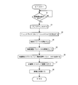
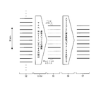
次に、標本Tの観察画像を取得する際の制御部53の動作の詳細について図2のフローチャートおよび図3のタイミング図を参照して説明する。
なお、観察開始の指示に先だって、ユーザは、操作部51を操作して、ステージ29を移動し、標本Tのうち、観察対象となる部分を対物レンズ28の視野中心に配置する。また、Z方向についてもステージ29を移動し、観察対象となる部分に対して、おおよその焦点合わせを行う。なお、ユーザは、これらの調整を、撮像部32により取得され、表示部52に表示される観察画像を目視して行うことができる。また、共焦点顕微鏡システム1が、位相差観察可能な構成を有する場合には、ユーザは、この位相差画像を目視して、上述した調整を行っても良い。
ステップS1において、制御部53は、観察開始指示が行われたか否かを判定する。制御部53は、観察開始指示が行われたと判定するまで待機し、観察開始指示が行われたと判定するとステップS2に進む。観察開始指示は、操作部51を介したユーザ操作により行われる。また、共焦点顕微鏡システム1が、タイマーなどを有する場合には、このタイマーに基づいて制御部53自身が観察開始指示を行っても良い。
ステップS2において、制御部53は、各部を制御し、プレスキャンを行う。このプレスキャンは、後述するステップS3において、TopスライスおよびBottomスライスを検出することを目的としたスキャンである。制御部53は、ステージ29をZ方向に移動しつつ、撮像部29による撮像を行い、複数のプレスキャン画像を取得する。
なお、プレスキャンは、所定の照明条件、撮像条件で行われる。例えば、撮像条件については、実際の観察(以下、「本観察」と称する)を行う際よりも、低解像度であっても良い。また、プレスキャンにおけるZ方向の開始点および終了点は、例えば、観察開始指示が行われた時点のZ方向の位置を基準とし、上下に所定の幅だけ移動した位置とする。また、プレスキャンの間隔(ステージ29の移動速度および撮像部32による撮像間隔)は、操作部51を介したユーザ操作などにより予め指定されても良いし、制御部53により自動で指定しても良い。
ステップS3において、制御部53は、ステップS2で行ったプレスキャンにより得られた複数のプレスキャン画像に基づいて、TopスライスおよびBottomスライスを検出する。
制御部53は、まず、ステップS2で得られた複数のプレスキャン画像のそれぞれについて、輝度分布のヒストグラムを求め、対象物(例えば、細胞など)の有無を判断する。対象物の有無は、プレスキャン実行時の照明条件および撮像条件に基づいて予め定められる閾値と、各プレスキャン画像の輝度値との比較により判断することができる。なお、上述した閾値は、操作部51を介したユーザ操作などにより指定可能としても良い。
制御部53は、例えば、対物レンズ28に近い方から順に、Z方向に沿って対象物の有無を判断し、最初に「対象物が有る」と判断したプレスキャン画像をTopスライスとする。さらに、制御部53は、Z方向に沿って対象物の有無を判断し、「対象物が有る」から「対象物が無い」に変化したプレスキャン画像をBottomスライスとする。
なお、より正確にTopスライスおよびBottomスライスを検出する場合には、「対象物が無い」から「対象物が有る」に変化した時点、および、「対象物が有る」から「対象物が無い」に変化した時点で、1枚前のプレスキャン画像に関する対象物の有無の判断を、閾値に関する条件を狭く変更して再び行っても良い。このような構成とすれば、山登りAFのように、より正確にTopスライスおよびBottomスライスを検出することができる。
また、検出したTopスライスおよびBottomスライスは、後述する本観察の際のZ方向の移動範囲に反映される。そのため、この移動範囲に、対象物の存在する部分を確実に含ませるために、Topスライスは対物レンズ28により近い位置とし、Bottomスライスは対物レンズ28からより遠い位置としても良い。例えば、Topスライスについては、最初に「対象物が有る」と判断したプレスキャン画像よりも、対物レンズ28側に近いプレスキャン画像をTopスライスとし、Bottomスライスについては、「対象物が有る」から「対象物が無い」に変化したプレスキャン画像よりも、対物レンズ28から遠いプレスキャン画像をBottomスライスとしても良い。
なお、ステップS2で説明したプレスキャンとステップS3で説明したTopスライスおよびBottomスライスの検出とを同時に行っても良い。すなわち、制御部53は、プレスキャン画像を取得するたびに対象物の有無を判断する。このような構成とすることにより、Topスライスを検出するまではプレスキャンの間隔を狭くし、Topスライスを検出した後はプレスキャンの間隔を広くするなど、より適切かつ無駄の無いプレスキャンを行うことも可能である。
ステップS4において、制御部53は、ステップS3で検出したTopスライスおよびBottomスライスを基準として、基準スライスを選択する。基準スライスは、後述するステップS5において、輝度調整パラメータの調整を行う対象となるスライスである。TopスライスおよびBottomスライスを基準としてどのようなスライスを基準スライスとして選択するかは、予め定められていても良いし、操作部51を介したユーザ操作などにより指定可能としても良い。ここでは、TopスライスおよびBottomスライスに加えて、TopスライスおよびBottomスライスの1/3および2/3に該当するスライスの計4スライスを基準スライスとして選択するものとして説明する。
ステップS5において、制御部53は、ステップS4において選択した基準スライスに対して輝度調整パラメータの調整を行う。ここでは、輝度調整パラメータとして、光源部10におけるレーザー光源のレーザー強度を例にあげて説明する。
制御部53は、ステップS4において選択した基準スライスのそれぞれについて、レーザー強度を調節しつつ、撮像部32による撮像を行う。そして、撮像により得られた画像から指標値を求めて、閾値と比較することにより最適な輝度調整パラメータを決定する。指標値は、輝度のヒストグラムや輝度飽和ピクセル数などである。例えば、輝度値が0~4095であって、輝度値が4095である画素(輝度飽和ピクセル)の比率が0.05~0.06%である場合には、その時のレーザー強度が最適な輝度調整パラメータであると判断することができる。
なお、輝度調整パラメータは、予めリニアリティ補正されているものとする。また、レーザー強度を調節しつつ、撮像部32による撮像を行って得られた画像を表示部52に表示しても良い。
さらに、所定回数の調節を行っても最適な輝度調整パラメータを求められない場合には、指標値と比較する閾値を変更し、条件を緩くして再度最適な輝度調整パラメータを求めても良い。また、表示部52などを利用して、最適な輝度調整パラメータを求められないことをユーザに報知しても良い。
このようにして求めた基準スライスごとの輝度調整パラメータは、スライスごとに異なる値となる。輝度調整パラメータがレーザー強度である場合には、対物レンズ28から遠いスライスほど、レーザー強度の値は大きくなる。
ステップS6において、制御部53は、ステップS5で行った輝度調整パラメータの調整結果に基づいて、本観察のスライスごとに輝度調整パラメータを決定する。
制御部53は、後述するステップS7における本観察のスライスごとの輝度調整パラメータを求める。本観察の対象となるスライスは、予め定められていても良いし、操作部51を介したユーザ操作などにより指定可能としても良い。ここでは、ステップS3で検出したTopスライスからBottomスライスの間で、ステップS2で行ったプレスキャンと同じ間隔のスライスを本観察の対象とする。
制御部53は、例えば、ステップS5で求めた基準スライスの輝度調整パラメータを用いてスプライン補間を行い、各スライスの輝度調整パラメータを決定する。なお、直線補間など、スプライン補間以外の補間方法を用いても良い。また、ステップS4で選択した基準スライスの数に応じて補間方法を決定しても良い。
ステップS7において、制御部53は、各部を制御し、本観察(Zスタック観察)を行う。制御部53は、ステージ29をZ方向に移動しつつ、撮像部29による撮像を行い、複数の観察画像を取得する。
なお、本観察は、ステップS6で決定したスライスごとの輝度調整パラメータを用いて行われる。すなわち、制御部53は、ステージ29をZ方向に移動するたびに、そのスライスの輝度調整パラメータを用いて撮像部29による撮像を行う。なお、本観察の際には、撮像により得られた複数の観察画像から3次元画像を生成しても良い。
ステップS8において、制御部53は、ステップS7で行った本観察により生成した複数の観察画像を記録部(不図示)に記録し、一連の処理を終了する。なお、ステップS7において3次元画像を生成した際には、制御部53は、3次元画像のみを記録しても良いし、3次元画像とともに複数の観察画像を記録しても良い。さらに、画像を記録する際に、ステップS6で決定したスライスごとの輝度調整パラメータを画像と関連付けて記録しても良い。
<実施形態の追加>
ステップS2およびステップS3を行わずに、所定の条件にしたがってステップS4で説明した基準スライスを選択しても良い。例えば、観察開始指示が行われた時点のZ方向の位置を基準とし、上下に所定の幅だけ移動した位置を基準スライスとしても良い。
ステップS2およびステップS3を行わずに、所定の条件にしたがってステップS4で説明した基準スライスを選択しても良い。例えば、観察開始指示が行われた時点のZ方向の位置を基準とし、上下に所定の幅だけ移動した位置を基準スライスとしても良い。
ステップS5以降において、輝度調整パラメータとして、光源部10におけるレーザー光源のレーザー強度を例にあげて説明したが、最終的に撮像部32に入射する入射光の強度(輝度)を調整可能な他のパラメータを用いても良い。例えば、スキャン速度(1ラインにレーザー光を照射する時間など)を輝度調整パラメータとしても良いし、電圧調整による光源部10のゲインを輝度調整パラメータとしても良い。また、2つ以上のパラメータを組み合わせて用いても良い。それぞれのパラメータは、照明光の強度、観察に要する時間、撮像部32により得られる画像の画質、標本Tに与える影響等が異なる。そのため、標本Tの種類や観察の目的などに合わせて適宜輝度調整パラメータを選択可能な構成としても良い。さらに、上記した以外の輝度調整パラメータを用いても良い。
図3の例では、プレスキャン時のスライスの何れかを基準スライスとして選択する場合を例示したが、プレスキャン時のスライスの中間に相当するスライスを基準スライスとして選択しても良い。また、図3の例では、プレスキャン時のスライスの間隔と、本観察時のスライスの間隔とが一致している場合を例示したが、これらは必ずしも一致していなくても良い。いずれの場合も、補間演算などにより対処することができる。
図2のフローで説明した一連の処理を自動で行わずに、ユーザの認証を受けて次のステップに進んでも良い。例えば、ステップS3のTopスライスおよびBottomスライスの検出後、ステップS4の基準スライス選択後、ステップS6の輝度調整パラメータ決定後などに、ユーザによる確認ステップを設けても良い。
ステップS4で選択した基準スライスや、ステップS6で決定した輝度調整パラメータなどをデータベース化して記録しておき、以降の観察時に利用しても良い。例えば、標本Tの種類(Topスライス、Bottomスライス等を含む)や観察の条件(プレスキャン時のスライスの間隔、本観察時のスライスの間隔など)が異なる観察を行う際に、制御部53は、データベースから、以前行った観察時に記録した基準スライスや輝度調整パラメータなどを読み出し、条件に応じて適宜演算を行って微調整する。このようにすれば、改めて図2のフローのステップS2からステップS6で説明した処理を行うことなく、適切な本観察を行うことができる。
以上説明したように、本実施形態によれば、対物レンズと、被検物を載置するステージと、被検物の像を撮像する撮像部と、対物レンズの光軸方向において、対物レンズとステージとの相対的な位置を変更する移動部とを備え、光軸方向における位置が異なる少なくとも2つの被検物内の面のそれぞれについて、輝度調整パラメータを求め、少なくとも2つの輝度調整パラメータに基づいて、光軸方向における位置が異なる複数の被検物内の面のそれぞれにおいて、撮像部による撮像を行う際の輝度調整パラメータを決定する。したがって、対物レンズからの距離に関係なく略同様の明るさの画像を取得することができる。このとき、ユーザは、照明条件や撮影条件などをスライスごとに指定する必要がない。そのため、対物レンズの光軸方向における位置が異なる複数の画像を生成する際に、生成される複数の画像における明るさのバラツキを抑えることができる。
なお、本実施形態の図1で説明した以外の構成を有する顕微鏡装置にも、本発明を同様に適用することができる。例えば、従来から共焦点顕微鏡において一般的であるピンホール式の共焦点絞りを組み合わせても良い。すなわち、上述したスリット状の開口部を有する共焦点スリット絞りとピンホール式の共焦点絞りとを備え、使用する対物レンズの種類や観察対象である試料の種類等に応じて、適宜交換して使用する構成としても良い。
また、本実施形態では、光源部10と共焦点顕微鏡20とコンピュータ50とからなる共焦点顕微鏡システム1を例に挙げて説明したが、本発明はこの例に限定されない。例えば、本実施形態では、スキャナ25が照明系のスキャナと結像系のスキャナとを兼用する例を示したが、照明系のスキャナと結像系のスキャナとを独立に設ける構成でも良い。また、撮像部(単純な光検出器や電子カメラなどを含む)を交換可能な共焦点顕微鏡にも本発明を同様に適用することができる。さらに、本実施形態で説明した光源部やコンピュータを内蔵した共焦点顕微鏡にも本発明を同様に適用することができる。
1…共焦点顕微鏡システム,10…光源部,20…共焦点顕微鏡,29…ステージ,32…撮像部,50…コンピュータ,53…制御部
Claims (8)
- 対物レンズと、
被検物を載置するステージと、
前記被検物の像を撮像する撮像部と、
前記対物レンズの光軸方向において、前記対物レンズと前記ステージとの相対的な位置を変更する移動部と、
前記光軸方向における位置が異なる少なくとも2つの前記被検物内の面のそれぞれについて、輝度調整パラメータを求める算出部と、
少なくとも2つの前記輝度調整パラメータに基づいて、前記光軸方向における位置が異なる複数の前記被検物内の面のそれぞれにおいて、前記撮像部による撮像を行う際の輝度調整パラメータを決定する決定部と
を備えたことを特徴とする顕微鏡装置。 - 請求項1に記載の顕微鏡装置において、
前記輝度調整パラメータは、前記被検物を照明する際の照明強度と、前記ステージの移動速度と、前記撮像部による撮像の時間間隔との少なくとも1つを含む
ことを特徴とする顕微鏡装置。 - 請求項2に記載の顕微鏡装置において、
前記被検物にレーザー光を照射する照明部を備え、
前記輝度調整パラメータは、前記照明強度として、前記レーザー光の強度と、前記レーザー光を光源から発生させる際のゲインとの少なくとも一方を含む
ことを特徴とする顕微鏡装置。 - 請求項1から請求項3の何れか1項に記載の顕微鏡装置において、
前記決定部は、少なくとも2つの前記輝度調整パラメータに基づいて、補間演算を行い、前記光軸方向における位置が異なる複数の面のそれぞれにおいて前記撮像部による撮像を行う際の輝度調整パラメータを決定する
ことを特徴とする顕微鏡装置。 - 請求項1から請求項4の何れか1項に記載の顕微鏡装置において、
前記移動部により前記ステージを所定の速度で移動しつつ、前記撮像部による撮像を所定の時間間隔で行い、複数のプレスキャン画像を生成する制御部を備え、
前記算出部は、複数の前記プレスキャン画像に基づいて、前記被検物の前記光軸方向における基準面を推測し、前記基準面を含む複数の面のそれぞれについて、前記輝度調整パラメータを求める
ことを特徴とする顕微鏡装置。 - 請求項1から請求項5の何れか1項に記載の顕微鏡装置において、
前記制御部は、前記決定部により決定した前記輝度パラメータに基づいて、前記移動部により前記ステージを移動しつつ、前記撮像部による撮像を行い、複数の観察画像を生成する
ことを特徴とする顕微鏡装置。 - 請求項6に記載の顕微鏡装置において、
複数の前記観察画像に基づいて、前記被検物の3次元画像を生成する3次元画像生成部を備える
ことを特徴とする顕微鏡装置。 - 対物レンズと、被検物を載置するステージと、前記被検物の像を撮像する撮像部と、前記対物レンズの光軸方向において、前記対物レンズと前記ステージとの相対的な位置を変更する移動部とを備えた顕微鏡装置の制御をコンピュータで実現するための制御プログラムであって、
前記光軸方向における位置が異なる少なくとも2つの前記被検物内の面のそれぞれについて、輝度調整パラメータを求める算出ステップと、
少なくとも2つの前記輝度調整パラメータに基づいて、前記光軸方向における位置が異なる複数の前記被検物内の面のそれぞれにおいて、前記撮像部による撮像を行う際の輝度調整パラメータを決定する決定ステップと
を備えたことを特徴とする制御プログラム。
Priority Applications (1)
| Application Number | Priority Date | Filing Date | Title |
|---|---|---|---|
| JP2011518268A JPWO2010143375A1 (ja) | 2009-06-10 | 2010-06-02 | 顕微鏡装置および制御プログラム |
Applications Claiming Priority (2)
| Application Number | Priority Date | Filing Date | Title |
|---|---|---|---|
| JP2009-139233 | 2009-06-10 | ||
| JP2009139233 | 2009-06-10 |
Publications (1)
| Publication Number | Publication Date |
|---|---|
| WO2010143375A1 true WO2010143375A1 (ja) | 2010-12-16 |
Family
ID=43308638
Family Applications (1)
| Application Number | Title | Priority Date | Filing Date |
|---|---|---|---|
| PCT/JP2010/003681 Ceased WO2010143375A1 (ja) | 2009-06-10 | 2010-06-02 | 顕微鏡装置および制御プログラム |
Country Status (2)
| Country | Link |
|---|---|
| JP (1) | JPWO2010143375A1 (ja) |
| WO (1) | WO2010143375A1 (ja) |
Cited By (5)
| Publication number | Priority date | Publication date | Assignee | Title |
|---|---|---|---|---|
| JP2012173391A (ja) * | 2011-02-18 | 2012-09-10 | Canon Inc | 画像生成装置、及び、画像生成方法 |
| US20130070054A1 (en) * | 2011-09-20 | 2013-03-21 | Olympus Corporation | Image processing apparatus, fluorescence microscope apparatus, and image processing program |
| JP2016520208A (ja) * | 2013-04-30 | 2016-07-11 | モレキュラー デバイシーズ, エルエルシー | 顕微鏡システムにおいて平行撮像を用いて焦点の合った画像を生成するための装置および方法 |
| JP2019526836A (ja) * | 2016-09-01 | 2019-09-19 | ライカ マイクロシステムズ シーエムエス ゲゼルシャフト ミット ベシュレンクテル ハフツングLeica Microsystems CMS GmbH | マイクロレンズアレイを有する、個々に照明される斜面を観察するための顕微鏡 |
| JP2020171198A (ja) * | 2019-04-08 | 2020-10-22 | 株式会社ニコン | 測定条件設定装置、及び、測定条件設定方法 |
Citations (3)
| Publication number | Priority date | Publication date | Assignee | Title |
|---|---|---|---|---|
| JPH06308390A (ja) * | 1993-04-26 | 1994-11-04 | Yokogawa Electric Corp | 共焦点顕微鏡 |
| JPH0712525A (ja) * | 1993-06-21 | 1995-01-17 | Ishikawajima Harima Heavy Ind Co Ltd | 共焦点走査方式レーザ顕微鏡を用いた厚さ計測装置 |
| JPH11183803A (ja) * | 1997-12-22 | 1999-07-09 | Yokogawa Electric Corp | 共焦点顕微鏡装置 |
-
2010
- 2010-06-02 WO PCT/JP2010/003681 patent/WO2010143375A1/ja not_active Ceased
- 2010-06-02 JP JP2011518268A patent/JPWO2010143375A1/ja not_active Withdrawn
Patent Citations (3)
| Publication number | Priority date | Publication date | Assignee | Title |
|---|---|---|---|---|
| JPH06308390A (ja) * | 1993-04-26 | 1994-11-04 | Yokogawa Electric Corp | 共焦点顕微鏡 |
| JPH0712525A (ja) * | 1993-06-21 | 1995-01-17 | Ishikawajima Harima Heavy Ind Co Ltd | 共焦点走査方式レーザ顕微鏡を用いた厚さ計測装置 |
| JPH11183803A (ja) * | 1997-12-22 | 1999-07-09 | Yokogawa Electric Corp | 共焦点顕微鏡装置 |
Cited By (9)
| Publication number | Priority date | Publication date | Assignee | Title |
|---|---|---|---|---|
| JP2012173391A (ja) * | 2011-02-18 | 2012-09-10 | Canon Inc | 画像生成装置、及び、画像生成方法 |
| US20130070054A1 (en) * | 2011-09-20 | 2013-03-21 | Olympus Corporation | Image processing apparatus, fluorescence microscope apparatus, and image processing program |
| EP2573607A3 (en) * | 2011-09-20 | 2014-01-22 | Olympus Corporation | Image processing apparatus, fluorescence microscope apparatus, and image processing program |
| US9279973B2 (en) | 2011-09-20 | 2016-03-08 | Olympus Corporation | Image processing apparatus, fluorescence microscope apparatus, and image processing program |
| JP2016520208A (ja) * | 2013-04-30 | 2016-07-11 | モレキュラー デバイシーズ, エルエルシー | 顕微鏡システムにおいて平行撮像を用いて焦点の合った画像を生成するための装置および方法 |
| JP2019526836A (ja) * | 2016-09-01 | 2019-09-19 | ライカ マイクロシステムズ シーエムエス ゲゼルシャフト ミット ベシュレンクテル ハフツングLeica Microsystems CMS GmbH | マイクロレンズアレイを有する、個々に照明される斜面を観察するための顕微鏡 |
| JP7130625B2 (ja) | 2016-09-01 | 2022-09-05 | ライカ マイクロシステムズ シーエムエス ゲゼルシャフト ミット ベシュレンクテル ハフツング | マイクロレンズアレイを有する、個々に照明される斜面を観察するための顕微鏡 |
| JP2020171198A (ja) * | 2019-04-08 | 2020-10-22 | 株式会社ニコン | 測定条件設定装置、及び、測定条件設定方法 |
| JP7379853B2 (ja) | 2019-04-08 | 2023-11-15 | 株式会社ニコン | 顕微鏡、及び、顕微鏡の設定方法 |
Also Published As
| Publication number | Publication date |
|---|---|
| JPWO2010143375A1 (ja) | 2012-11-22 |
Similar Documents
| Publication | Publication Date | Title |
|---|---|---|
| JP5982405B2 (ja) | オートフォーカス装置を有する顕微鏡及び顕微鏡でのオートフォーカス方法 | |
| US7436590B2 (en) | Scanning laser microscope apparatus and light-amount detection unit | |
| US7709773B2 (en) | Scanning optical device which sets hardware in association with a depth of a focus position based on hardware set values stored in association with depths of focus positions | |
| KR101106852B1 (ko) | 광학식 3차원 계측 장치 및 필터 처리 방법 | |
| JP5941395B2 (ja) | 画像取得装置及び画像取得装置のフォーカス方法 | |
| JP5784435B2 (ja) | 画像処理装置、蛍光顕微鏡装置および画像処理プログラム | |
| JP5814709B2 (ja) | タイムラプス観察方法、及び、それに用いられるタイムラプス観察装置 | |
| JP5202936B2 (ja) | 走査型顕微鏡 | |
| JP6363477B2 (ja) | 3次元形状測定装置 | |
| JPWO2010143375A1 (ja) | 顕微鏡装置および制御プログラム | |
| JP5053691B2 (ja) | 標本スキャナ装置、該装置による標本位置検出方法 | |
| JP2006023476A (ja) | 共焦点走査型顕微鏡 | |
| JP2015069202A (ja) | 顕微鏡システム | |
| JP5572464B2 (ja) | 共焦点顕微鏡装置 | |
| KR100971582B1 (ko) | 공초점 현미경 | |
| JP4179790B2 (ja) | 共焦点走査型光学顕微鏡 | |
| JP4812325B2 (ja) | 走査型共焦点顕微鏡および試料情報測定方法 | |
| JP2019190851A (ja) | 走査型プローブ顕微鏡 | |
| WO2022145391A1 (ja) | 走査型共焦点顕微鏡および走査型共焦点顕微鏡の調整方法 | |
| JP2010164635A (ja) | 共焦点顕微鏡 | |
| JPH1138324A (ja) | レーザ走査顕微鏡 | |
| JP2011237616A (ja) | 走査型顕微鏡 | |
| JP6552793B2 (ja) | 標本観察装置 | |
| JP2007286284A (ja) | 共焦点走査型顕微鏡システム、及びそれを使用した観察方法 | |
| JP7839836B2 (ja) | 光学装置及び光学装置の補正方法 |
Legal Events
| Date | Code | Title | Description |
|---|---|---|---|
| 121 | Ep: the epo has been informed by wipo that ep was designated in this application |
Ref document number: 10785907 Country of ref document: EP Kind code of ref document: A1 |
|
| WWE | Wipo information: entry into national phase |
Ref document number: 2011518268 Country of ref document: JP |
|
| NENP | Non-entry into the national phase |
Ref country code: DE |
|
| 122 | Ep: pct application non-entry in european phase |
Ref document number: 10785907 Country of ref document: EP Kind code of ref document: A1 |